EP3936923A1 - Light guide device - Google Patents
Light guide device Download PDFInfo
- Publication number
- EP3936923A1 EP3936923A1 EP20767145.4A EP20767145A EP3936923A1 EP 3936923 A1 EP3936923 A1 EP 3936923A1 EP 20767145 A EP20767145 A EP 20767145A EP 3936923 A1 EP3936923 A1 EP 3936923A1
- Authority
- EP
- European Patent Office
- Prior art keywords
- light guide
- light
- guide member
- reflection
- incident
- Prior art date
- Legal status (The legal status is an assumption and is not a legal conclusion. Google has not performed a legal analysis and makes no representation as to the accuracy of the status listed.)
- Granted
Links
Images





Classifications
-
- B—PERFORMING OPERATIONS; TRANSPORTING
- B23—MACHINE TOOLS; METAL-WORKING NOT OTHERWISE PROVIDED FOR
- B23K—SOLDERING OR UNSOLDERING; WELDING; CLADDING OR PLATING BY SOLDERING OR WELDING; CUTTING BY APPLYING HEAT LOCALLY, e.g. FLAME CUTTING; WORKING BY LASER BEAM
- B23K26/00—Working by laser beam, e.g. welding, cutting or boring
- B23K26/08—Devices involving relative movement between laser beam and workpiece
- B23K26/082—Scanning systems, i.e. devices involving movement of the laser beam relative to the laser head
-
- G—PHYSICS
- G02—OPTICS
- G02B—OPTICAL ELEMENTS, SYSTEMS OR APPARATUS
- G02B26/00—Optical devices or arrangements for the control of light using movable or deformable optical elements
- G02B26/08—Optical devices or arrangements for the control of light using movable or deformable optical elements for controlling the direction of light
- G02B26/0816—Optical devices or arrangements for the control of light using movable or deformable optical elements for controlling the direction of light by means of one or more reflecting elements
-
- G—PHYSICS
- G02—OPTICS
- G02B—OPTICAL ELEMENTS, SYSTEMS OR APPARATUS
- G02B26/00—Optical devices or arrangements for the control of light using movable or deformable optical elements
- G02B26/08—Optical devices or arrangements for the control of light using movable or deformable optical elements for controlling the direction of light
- G02B26/10—Scanning systems
- G02B26/105—Scanning systems with one or more pivoting mirrors or galvano-mirrors
-
- G—PHYSICS
- G02—OPTICS
- G02B—OPTICAL ELEMENTS, SYSTEMS OR APPARATUS
- G02B26/00—Optical devices or arrangements for the control of light using movable or deformable optical elements
- G02B26/08—Optical devices or arrangements for the control of light using movable or deformable optical elements for controlling the direction of light
- G02B26/10—Scanning systems
- G02B26/12—Scanning systems using multifaceted mirrors
-
- G—PHYSICS
- G02—OPTICS
- G02B—OPTICAL ELEMENTS, SYSTEMS OR APPARATUS
- G02B27/00—Optical systems or apparatus not provided for by any of the groups G02B1/00 - G02B26/00, G02B30/00
- G02B27/09—Beam shaping, e.g. changing the cross-sectional area, not otherwise provided for
- G02B27/0933—Systems for active beam shaping by rapid movement of an element
-
- G—PHYSICS
- G02—OPTICS
- G02B—OPTICAL ELEMENTS, SYSTEMS OR APPARATUS
- G02B27/00—Optical systems or apparatus not provided for by any of the groups G02B1/00 - G02B26/00, G02B30/00
- G02B27/09—Beam shaping, e.g. changing the cross-sectional area, not otherwise provided for
- G02B27/0938—Using specific optical elements
- G02B27/0977—Reflective elements
-
- G—PHYSICS
- G02—OPTICS
- G02B—OPTICAL ELEMENTS, SYSTEMS OR APPARATUS
- G02B5/00—Optical elements other than lenses
- G02B5/08—Mirrors
-
- G—PHYSICS
- G02—OPTICS
- G02B—OPTICAL ELEMENTS, SYSTEMS OR APPARATUS
- G02B7/00—Mountings, adjusting means, or light-tight connections, for optical elements
- G02B7/18—Mountings, adjusting means, or light-tight connections, for optical elements for prisms; for mirrors
- G02B7/182—Mountings, adjusting means, or light-tight connections, for optical elements for prisms; for mirrors for mirrors
- G02B7/1821—Mountings, adjusting means, or light-tight connections, for optical elements for prisms; for mirrors for mirrors for rotating or oscillating mirrors
Definitions
- the present invention relates to a light guide device.
- PTL 1 discloses a beam scanning device provided in this type of apparatus.
- the beam scanning device of PTL 1 is provided with a rotating polyhedral mirror, a plurality of scanning units, a beam switching member, and a beam switching control unit.
- a beam from a light source device is incident on the beam switching member.
- the beam switching control unit is configured to control the beam switching member so that deflection of the beam by the rotating polyhedral mirror of the scanning unit is repeated for each reflection surface of the rotating polyhedral mirror, and to cause each of the plurality of the scanning units to perform one-dimensional scanning of the spot light (beam) in turn.
- the beam switching member is electrically controlled by the beam switching control unit to switch the light path of the beam so that the beam from the light source device is incident on one scanning unit. Accordingly, the structure for switching the light path of the beam is complicated, and there is room for improvement in this respect.
- the present invention is made in view of the circumstances described above, and an object of the present invention is to provide a light guide device capable of switching a scanning area with a simple structure.
- the light guide device includes a plurality of reflection units that reflect incident light so as to guide the incident light to irradiate an object.
- the plurality of the reflection units are lined up along a traveling direction of the incident light.
- Each of the plurality of the reflection units includes a first light guide member that reflects the incident light.
- Each of the plurality of the reflection units is switched between a reflecting state in which the first light guide member reflects the incident light by being hit by the incident light and a passing state in which the first light guide member lets the incident light pass through without being hit by the incident light by rotating the first light guide member. Timing of being in the reflecting state differs among the plurality of the reflection units.
- the reflected light due to reflection of the incident light is deflected as the first light guide member rotates.
- the reflected light is led to an irradiated point included in a scanning area in which the reflection unit scans the object to be irradiated.
- the scanning areas of the plurality of the reflection units are lined up in parallel with the traveling direction of the incident light.
- the reflection unit that reflects the incident light can be mechanically changed to switch the scanning area to the irradiated object. Accordingly, the switching of the scanning area can be performed with a simple configuration.
- a light guide device capable of switching a scanning area with a simple structure can be provided.
- FIG. 1 is a diagonal view of the laser processing device 1.
- the laser processing device 1 shown in FIG. 1 can process the workpiece 100 by irradiating a laser beam onto the workpiece (irradiated object) 100 while scanning the workpiece 100 by light.
- the laser processing device 1 can perform non-thermal processing.
- the non-thermal processing includes ablation processing.
- the ablation processing is a processing in which a part of the workpiece 100 is vaporized by irradiating the laser beam to the part of the workpiece 100.
- the laser processing device 1 may be configured to perform thermal processing in which the workpiece 100 is melted by the heat of the laser beam.
- the workpiece 100 is a plate-like member.
- the workpiece 100 is made of, for example, CFRP (carbon fiber reinforced plastic).
- CFRP carbon fiber reinforced plastic
- the workpiece 100 is not limited to a plate-like member and may be, for example, a block-like member. Also, the workpiece 100 may be made of other materials.
- the laser beam used in the laser processing device 1 may be visible light or electromagnetic waves in a wavelength band other than visible light.
- visible light not only visible light but also various electromagnetic waves with a wider wavelength band than that are included are referred to as "light”.
- the laser processing device 1 includes a conveyance section 11, a laser generator 12, a light guide device 13.
- the conveyance section 11 can move the workpiece 100 in a direction that is substantially perpendicular to the main scanning direction of the laser processing device 1. Laser processing is performed while the workpiece 100 is moved by the conveyance section 11.
- the conveyance section 11 is a belt conveyor.
- the conveyance section 11 is not particularly limited.
- the conveyance section 11 may be a roller conveyor, or may be a configuration in which the workpiece 100 is grasped and conveyed.
- the conveyance section 11 can be omitted and processing can be performed by irradiating the laser beam to the workpiece 100 which is fixed so as not to move.
- the laser generator 12 is a light source of the laser beam and can generate a pulsed laser with a short time width by pulse oscillation.
- the time width of the pulsed laser is not particularly limited.
- the time width is a short time interval such as a nanosecond order, a picosecond order, or a femtosecond order, for example.
- the laser generator 12 may be configured to generate a CW laser by continuous wave oscillation.
- the light guide device 13 guides the laser beam generated by the laser generator 12 to irradiate the workpiece 100.
- the laser beam guided by the light guide device 13 is irradiated to an irradiated point 102 on a scanning line 101 defined on the surface of the workpiece 100.
- the light guide device 13 causes the irradiated point 102, to which the workpiece 100 is irradiated by the laser beam, to move at a substantially constant speed along the straight scanning line 101. In this way, the light scanning is realized.
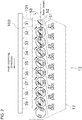
- FIG. 2 is a schematic diagram of the light guide device 13.
- the light guide device 13 includes a plurality of reflection units 20.
- the plurality of the reflection units 20 are disposed inside a housing 17 provided by the light guide device 13.
- the plurality of the reflection units 20 each reflect the laser beam incident from the laser generator 12 and guide it to the workpiece 100.
- the laser beam incident from the laser generator 12 to the respective reflection units 20 may be referred to as the incident light.
- the plurality of the reflection units 20 are lined up straight along the traveling direction of the incident light.
- the direction in which the reflection units 20 are lined up also matches the longitudinal direction of the scanning line 101.
- Each of the plurality of the reflection units 20 is disposed at a position where the distance from the scanning line 101 is substantially equal.
- the reflection unit 20 located at the most upstream side in the traveling direction of the incident light may be referred to as a first reflection unit 21.
- each of the remaining reflection units 20 may be referred to as a second reflection unit 22, a third reflection unit 23, a fourth reflection unit 24, a fifth reflection unit 25, a sixth reflection unit 26, a seventh reflection unit 27, an eighth reflection unit 28, and a ninth reflection unit 29, in order from the first reflection unit 21 to the downstream side in the traveling direction of the incident light.
- Each of the reflection units 20 can scan optically by deflecting and reflecting the laser beam.
- the area in which the workpiece 100 is optically scanned by each of the reflection units 20 (scanning area) is different from the scanning area by the other reflection units 20.
- FIG. 1 and FIG. 2 show a first scanning area 31, a second scanning area 32, a third scanning area 33, a fourth scanning area 34, a fifth scanning area 35, a sixth scanning area 36, a seventh scanning area 37, an eighth scanning area 38, and a ninth scanning area 39.
- the nine scanning areas are arranged in a straight arrangement. A set of these scanning areas constitutes a scanning line 101.
- the first scanning area 31 is scanned by the first reflection unit 21, and thereafter each scanning area is sequentially scanned by the corresponding reflection unit 20.
- the ninth scanning area 39 is scanned by the ninth reflection unit 29.
- Each of the reflection units 20 can iteratively switch between a reflecting state, in which it reflects the incident light and performs scanning, and a passing state, in which it does not reflect the incident light and passes it downstream.
- the reflection unit 20 is in the reflecting state, the corresponding scanning area (e.g., the first scanning area 31 in the case of the first reflection unit 21) is scanned by light.
- the reflection unit 20 is in the passing state, the corresponding reflection unit 20 does not perform the light scanning.
- Timing at which each of the reflection units 20 is in the reflecting state differs among the plurality of the reflection units 20.
- the plurality of the scanning areas are scanned respectively by switching the reflection units 20 that enter the reflecting state.
- the reflection units 20 that enter the reflecting state are switched one by one in order from the upstream side to the downstream side in the traveling direction of the incident light. Specifically, the reflection units 20 enter the reflecting state in the order of the first reflection unit 21, the second reflection unit 22, the third reflection unit 23, .... However, the reflection units 20 may be switched to the reflecting state in order from the downstream side, or in an order different from the order in which the reflection units 20 are lined up.
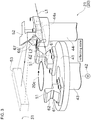
- FIG. 3 is a diagonal view showing a state in which one reflection unit 20 reflects the light.
- FIG. 4 is a diagonal view showing a state in which the reflection unit 20 passes through the light.
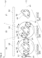
- FIG. 5 is a diagram showing a state in which the first reflection unit 21 of the plurality of the reflection units 20 reflects the light.
- FIG. 6 is a diagram showing a state in which the second reflection unit 22 reflects the light.
- FIG. 3 shows only the first reflection unit 21 of the nine reflection units 20. Since all of the nine reflection units 20 have the same configuration, the first reflection unit 21 will be described below as representative.
- the first reflection unit 21 includes a turntable (rotating member) 41, a motor (drive source) 42, a first light guide member 51, a second light guide member 52, and a scanning lens 53.
- the turntable 41 is a hollow disc-shaped member in the present embodiment and is rotatable about the rotational axis 20c.
- One end of a transmission shaft 43 which is formed in a hollow cylindrical shape, is fixed to the turntable 41.
- the transmission shaft 43 is rotatably supported by a housing not shown in the figure of the reflection unit 20.
- the motor 42 is capable of rotating the turntable 41. By transmitting the driving force of the motor 42 to the transmission shaft 43, the turntable 41 rotates together with the transmission shaft 43.
- the motor 42 is an electric motor in this embodiment but is not limited thereto.
- the first light guide member 51 is integrally provided with the turntable 41 so that it rotates around the rotational axis 20c. This rotational axis 20c is arranged to be orthogonal to the light path of the laser beam incident on the reflection unit 20.
- the light path of the laser beam incident on the reflection unit 20 may be referred to as the first light path L1.
- the reflection surface described below included by the first light guide member 51 can reflect the incident light by being hit by the incident light traveling along the first light path L1.
- the first light guide member 51 is fixed near the outer periphery of the turntable 41 using bolts or the like.
- Two or more even numbers of the first light guide members 51 are provided for one turntable 41 (one reflection unit 20).
- the plurality of the first light guide members 51 are identical in shape to each other.
- first light guide members 51 are provided for one turntable 41.
- the two first light guide members 51 are respectively arranged to divide 360° equally in the turntable 41.
- one first light guide member 51 is disposed at a position 180° displaced with respect to the other first light guide member 51.
- the first light guide member 51 is formed in a block shape by a metal such as aluminum.
- the first light guide member 51 includes a first reflection surface 61 and a second reflection surface 62.
- a cross-sectional V-shaped groove is formed in the first light guide member 51 to open the side far from the rotational axis 20c.
- the first reflection surface 61 and the second reflection surface 62 are formed on the inner wall of this groove.
- the first reflection surface 61 and the second reflection surface 62 are both formed in a planar shape.
- the first reflection surface 61 is inclined with respect to a virtual plane perpendicular to the rotational axis 20c.
- the second reflection surface 62 is inclined with respect to the virtual plane perpendicular to the rotational axis 20c.
- the first reflection surface 61 and the second reflection surface 62 are inclined with respect to the virtual plane perpendicular to the rotational axis 20c in opposite directions and at equal angles (specifically, 45°) to each other. Accordingly, the first reflection surface 61 and the second reflection surface 62 are arranged to form a V-shape.
- the two first light guide members 51 are disposed at positions corresponding to mutually opposite sides of a regular polygon (specifically, a regular 18-sided polygon). Accordingly, the central angle corresponding to one of the first light guide members 51 is 20°.
- the first light guide member 51 is not disposed at a position corresponding to a side other than the above-described opposing sides.
- the state in which the first light guide members 51 is hit by the laser beam incident on the reflection unit 20 and traveling along the first light path L1 and the state in which the first light guide members 51 is not hit by the laser beam are alternately switched.
- the state in which any of the two first light guide members 51 is hit by the incident light is the reflection state described above.
- the state in which none of the two first light guide members 51 is hit by the incident light is the passing state described above.
- the first light guide member 51 crosses the light path of the incident light twice for each 360° rotation.
- reflection surfaces (specifically, the first reflection surface 61 and the second reflection surface 62) that reflect the incident light are formed only on the side far from the rotational axis 20c.
- the reflection surface of the first light guide member 51 faces the upstream side of the traveling direction of the incident light, so that the light can be effectively reflected.
- the reflection surface of the first light guide member 51 faces the downstream side of the traveling direction of the incident light, so that even if light were to be hit by the first light guide member 51, the first light guide member 51 would not function effectively.
- any first light guide member 51 is arranged to be paired with other first light guide member 51 whose phase is 180° different from each other. Accordingly, at timing when the first light guide member 51 crosses the light path in a direction that does not effectively reflect the incident light, the other first light guide member 51 always crosses the light path in a direction that effectively reflects the incident light. Accordingly, since the first light guide member 51 whose reflection surface does not face the incident light does not substantially interfere with the passage of the incident light, the light can be used efficiently as a whole.
- the first light path L1 is perpendicular to the rotational axis 20c.
- the two first light guide members 51 are arranged with a phase difference of 180° with respect to each other. Accordingly, of the two first light guide members 51 placed across the rotational axis 20c, only the first light guide member 51 located on the side close to the upstream side of the first light path L1 is to be hit by the incident light.
- the first reflection surface 61 is arranged to overlap with the first light path L1 when the first light guide member 51 is in a predetermined rotational phase. Accordingly, the incident light is reflected by the first reflection surface 61, and then reflected by the second reflection surface 62.
- the first reflection surface 61 and the second reflection surface 62 of the first light guide member 51 are directed orthogonal to the rotational axis 20c.
- the directions of the first reflection surface 61 and the second reflection surface 62 change continuously. Accordingly, the direction of the light emitted from the second reflection surface 62 smoothly changes in the direction shown by the black filled arrows in FIG. 3 . Thus, a deflection of the emitted light is realized.
- first reflection surface 61 and the second reflection surface 62 are arranged in a V-shape, as the first light guide member 51 rotates, the emitted light is deflected along a plane perpendicular to the rotational axis 20c, as shown by the black filled arrows in FIG. 3 .
- This plane is offset in the direction of the rotational axis 20c with respect to the first light path L1. This allows the light emitted from the first light guide member 51 to enter the second light guide member 52.
- the laser beam is incident on the reflection unit 20 so as to be orthogonal to the rotational axis 20c.
- the rotational phase of the first light guide member 51 is perfectly matched with the direction of the incident light, when viewed along the rotational axis 20c, the first reflection surface 61 and the second reflection surface 62 are orthogonal to the incident light. Accordingly, at this time, the laser beam is reflected twice so as to be folded back by the first light guide member 51, and is emitted in a direction parallel and opposite to the direction of the first light path L1, as shown by the second light path L2 in FIG. 3 .
- the second light guide member 52 reflects the light emitted from the first light guide member 51 and guides it to a scanning area (first scanning area 31) corresponding to the first reflection unit 21.
- the second light guide member 52 is disposed at a position offset from the first light path L1 by an appropriate distance in the direction of the rotational axis 20c described above.
- the second light guide member 52 is fixed using a bolt or the like to an end portion on one side in the longitudinal direction of the fixed shaft 44 formed in an elongated shape.
- the fixed shaft 44 has an elongated recess 44a formed along the light path of the incident light. Accordingly, the laser beam from the laser generator 12 is not interrupted by the second light guide member 52 nor by the fixed shaft 44, but is led to the side of the first light guide member 51 through the recess 44a as a light passage path.
- the second light guide member 52 is formed in a block shape by a metal such as aluminum.
- the second light guide member 52 includes a first light guide reflection surface 66 and a second light guide reflection surface 67.
- a cross-sectional V-shaped groove is formed in the second light guide member 52 to open a side inclined at 45° to the direction of the first light path L1 when viewed along the rotational axis 20c.
- a first light guide reflection surface 66 and a second light guide reflection surface 67 are formed on the inner wall of this groove.
- the first light guide reflection surface 66 and the second light guide reflection surface 67 are both formed in a planar shape.
- the first light guide reflection surface 66 is inclined with respect to a virtual plane perpendicular to the rotational axis 20c.
- the second light guide reflection surface 67 is inclined with respect to the virtual plane perpendicular to the rotational axis 20c.
- the first light guide reflection surface 66 and the second light guide reflection surface 67 are inclined with respect to the virtual plane perpendicular to the rotational axis 20c in opposite directions and at equal angles (specifically, 45°) to each other. Accordingly, the first light guide reflection surface 66 and the second light guide reflection surface 67 are arranged to form a V-shape.
- the first light guide reflection surface 66 and the second light guide reflection surface 67 of the second light guide member 52 are arranged to cover a light deflection range by the first light guide member 51.
- the first light guide reflection surface 66 is placed corresponding to the above-described plane including the deflection range of the emitted light by the first light guide member 51. Accordingly, the laser beam is reflected by the first light guide reflection surface 66, and then reflected by the second light guide reflection surface 67.
- the scanning lens 53 is a free-form surface lens, for example, a known f ⁇ lens can be used.
- the scanning lens 53 is disposed between the second light guide member 52 and the first scanning area 31. With this scanning lens 53, the focal distance can be made constant in the center and the peripheral portions of the scanning range.
- reflection units 20 configured as described above are lined up along the traveling direction of the incident light from the laser generator 12 to constitute the light guide device 13 shown in FIG. 2 .
- the rotational axes 20c of the first light guide members 51 are parallel to each other.
- the first light guide members 51 rotate at an equal angular velocity and in the same direction as each other.
- the rotational phase of the first light guide member 51 differs among the plurality of the reflection units 20. This allows timing at which the first light guide member 51 is hit by the incident light to be different among the plurality of reflection units 20.
- the difference in the rotational phase of the first light guide member 51 between the two reflection units 20 increases by a certain angle (20° in the present embodiment) every time the reflection units 20 are separated by one. This allows the plurality of reflection units 20 to be switched to the reflecting state according to the order in which they are lined up.
- the rotation of the first light guide member 51 linked by the plurality of reflection units 20 can be realized, for example, by controlling the motors 42 provided by the plurality of the reflection units 20 to rotate synchronously.
- the interlocked rotation of the first light guide member 51 can also be realized by connecting the respective transmission shafts 43 to each other by gears or belts, and driving them by a common motor.
- FIG. 5 shows a case in which only the first reflection unit 21 of the nine reflection units 20 enters the reflecting state.
- FIG. 6 shows a case in which, as a result of the rotation of the first light guide member 51 of each of the reflection units 20 from the state of FIG. 5 , the first reflection unit 21 changes to a passing state and the second reflection unit 22 enters a reflecting state.
- the reflection units 20 that perform light scanning can be switched sequentially to realize light scanning along the long scanning line 101 as a whole.
- the transmission shaft 43 of the reflection unit 20 on the upstream side of the incident light is attached to the fixed shaft 44 of the reflection unit 20 on the downstream side. Accordingly, the first light guide member 51 of the upstream reflection unit 20 rotates around the second light guide member 52 of the downstream reflection unit 20. As described above, since the second light guide member 52 reflects light while offsetting it, light emitted from the second light guide member 52 is not interrupted by the rotating first light guide member 51. This arrangement makes it possible to downsize the light guide device 13 and to easily bring the scanning areas of the respective reflection units 20 into close proximity with each other.
- the light guide device 13 of the present embodiment includes the plurality of the reflection units 20 that reflect incident light so as to guide the incident light to irradiate on the workpiece 100.
- the plurality of the reflection units 20 are lined up along the traveling direction of the incident light.
- Each of the plurality of the reflection units 20 includes the first light guide member 51 that reflects the incident light.
- Each of the plurality of the reflection units 20 is switched between the reflecting state in which the first light guide member 51 reflects the incident light by being hit by the incident light and a passing state in which the first light guide member 51 lets the incident light pass through without being hit by the incident light by rotating the first light guide member 51. Timing of being in the reflecting state differs among the plurality of the reflection units 20.
- the reflected light due to the reflection of the incident light is deflected as the first light guide member 51 rotates.
- the reflected light is led to the irradiated point 102 included in the scanning area in which the reflection unit 20 scans the workpiece 100.
- the first scanning area 31 of the first reflection unit 21, the second scanning area 32 of the second reflection unit 22, ... are lined up in parallel with the traveling direction of the incident light.
- the reflection unit 20 that reflects the incident light can be mechanically changed to switch the scanning area to the workpiece 100. Accordingly, the switching of the scanning area can be performed with a simple configuration.
- the first light guide members 51 rotate at equal angular velocity and in the same direction as each other.
- the difference in the rotational phase of the first light guide member 51 between the two reflection units 20 increases by a certain angle for every one the reflection unit 20 apart.
- the plurality of the scanning areas can be scanned according to the order in which they are arranged.
- the rotational axes 20c of the first light guide members 51 are parallel to each other.
- the rotational axis 20c of the first light guide member 51 is orthogonal to the incident light.
- the first light guide member 51 in the reflecting state of the reflection unit 20, the first light guide member 51 reflects so as to deflect along the plane perpendicular to the rotational axis 20c of the first light guide member 51. This plane is offset in the direction of the rotational axis 20c with respect to the incident light to the reflection unit 20.
- Each of the plurality of the reflection units 20 includes a second light guide member 52. The second light guide member 52 reflects the reflected light reflected in the first light guide member 51 so as to guide to the scanning area.
- the flexibility of the position of the scanning area can be increased.
- a layout in which the second light guide member 52 does not interrupt the incident light which is to be incident to the reflection unit 20 can be realized.
- the first light guide member 51 includes the first reflection surface 61 and the second reflection surface 62.
- the first reflection surface 61 is formed in a planar shape that is inclined with respect to the plane perpendicular to the rotational axis 20c of the first light guide member 51.
- the second reflection surface 62 is formed in a planar shape inclined with respect to the plane perpendicular to the rotational axis 20c of the first light guide member 51.
- the direction in which the first reflection surface 61 is inclined relative to the plane perpendicular to the rotational axis 20c and the direction in which the second reflection surface 62 is inclined relative to the plane perpendicular to the rotational axis 20c are opposite. After the incident light is reflected by the first reflection surface 61, the incident light is reflected by the second reflection surface 62.
- the first light guide member 51 of the other reflection units 20 rotates.
- the second light guide member 52 reflects the light which is reflected by the first light guide member 51 while offsetting the light in the direction of the rotational axis 20c of the first light guide member 51.
- the second light guide member 52 includes the first light guide reflection surface 66 and the second light guide reflection surface 67.
- the first light guide reflection surface 66 is formed in a planar shape inclined with respect to the plane perpendicular to the rotational axis 20c of the first light guide member 51.
- the second light guide reflection surface 67 is formed in a planar shape inclined with respect to the plane perpendicular to the rotational axis 20c of the first light guide member 51.
- the direction in which the first light guide reflection surface 66 is inclined relative to the plane perpendicular to the rotational axis 20c and the direction in which the second light guide reflection surface 67 is inclined relative to the plane perpendicular to the rotational axis 20c are opposite. After the light which is reflected by the first light guide member 51 is reflected by the first light guide reflection surface 66, the light is reflected by the second light guide reflection surface 67.
- each of the plurality of the reflection units 20 two or more even numbers of first light guide members 51 are arranged so as to divide 360° at equal angular intervals.
- the reflection unit 20 can be switched to the reflecting state multiple times per one rotation. Since the plurality of the first light guide members 51 are all arranged in pairs across the rotational axis 20c, the incident light is not interrupted by the first light guide members 51 that are in a rotational phase other than the rotational phase in which the incident light is reflected for scanning.
- each of the plurality of the reflection units 20 includes the scanning lens 53.
- the scanning lens 53 is placed in the light path from the first light guide member 51 to the scanning area.
- the laser processing device 1 of this embodiment includes the light guide device 13.
- each of the plurality of the reflection units 20 light emitted from the first light guide member 51 which rotates is led to any irradiated point 102 included in the straight scanning line 101.
- the light path length from an incident position of the light to the first light guide member 51 to the irradiated point 102 is substantially constant over all the irradiated points in the scanning line 101.
- the scanning speed on the scanning line 101 of the light led from each of the plurality of the reflection units 20 is substantially constant.
- the reflection surface of the first light guide member 51 is arranged to be inclined at an angle of 45° to the incident light when viewed along the rotational axis 20c. Accordingly, in the reflection unit 20 of the modification, when viewed along the rotational axis 20c, the first light guide member 51 deflects the reflected light in an angular range centered on an orientation that is changed from the direction of the incident light by 90°.
- the reflection surface of the first light guide member 51 is tilted, which causes some distortion in the light scanning, but the second light guide member 52 can be eliminated. Therefore, there is no need to form a V-shaped groove in the first light guide member 51 as in the above-described embodiment.
- the reflection surface that reflects the incident light in the first light guide member 51 can be formed in a plane parallel to the rotational axis 20c.
- the number of reflection units 20 can be determined according to the shape of the irradiated object, such as its length. For example, three, four, or five units can be provided.
- the plurality of the reflection units 20 may be somewhat separated from each other.
- a mirror or the like that changes the direction of the incident light may be disposed between the plurality of the reflection units 20.
- the light guide device 13 may be configured to scan along a plurality of non-contiguous scanning lines 101.
- the plurality of the scanning lines 101 may be disposed apart in a longitudinal direction of the scanning lines 101, or may be disposed apart in a direction perpendicular to the longitudinal direction of the scanning lines 101.
- the plurality of the scanning lines 101 may be oriented differently from each other.
- the two reflection units 20 perform scanning along two scanning lines 101 arranged in parallel with a suitable distance between them.
- FIG. 8 shows a view in a direction perpendicular to the processing surface of the workpiece 100.
- the number of scanning lines 101 may be three or more.
- the number of the first light guide members 51 in each reflection unit 20 is two. This is not limited thereto and it may be four, six, or eight, for example.
- the central angle corresponding to the first light guide member 51 can also be changed as appropriate.
- the central angle can be changed so that the central angle is not 20° but a central angle (30°) corresponding to one side of a regular dodecagon.
- the first light guide member 51 of the reflection unit 20 which is adjacent to the reflection unit 20 on the upstream side of the traveling direction of the incident light than the reflection unit 20 rotates.
- the second light guide member 52 may be disposed between the reflection unit 20 and the adjacent reflection unit 20 located downstream in the traveling direction of the incident light relative to the reflection unit 20.
- the first reflection surface 61 and the second reflection surface 62 of the first light guide member 51 may be realized by a prism.
- the first light guide reflection surface 66 and the second light guide reflection surface 67 of the second light guide member 52 may be realized by a prism.
- the first light guide member 51 can be fixed to an arm-like rotating member, for example, instead of the turntable 41.
- the second light guide member 52 can be fixed to be suspended, for example, using a portal frame. In this case, it is not necessary to configure the turntable 41 and the transmission shaft 43 in a hollow form.
- the optical scanning device to which the light guide device 13 is applied is not limited to the laser processing device 1, but may be, for example, an image forming device.
Landscapes
- Physics & Mathematics (AREA)
- Optics & Photonics (AREA)
- General Physics & Mathematics (AREA)
- Engineering & Computer Science (AREA)
- Plasma & Fusion (AREA)
- Mechanical Engineering (AREA)
- Mechanical Optical Scanning Systems (AREA)
- Laser Beam Processing (AREA)
- Mechanical Light Control Or Optical Switches (AREA)
- Optical Elements Other Than Lenses (AREA)
- Mounting And Adjusting Of Optical Elements (AREA)
Abstract
Description
- The present invention relates to a light guide device.
- Conventionally, a technique for scanning light from a light source along a straight scanning line has been widely used in image forming devices, laser processing devices, and the like.
PTL 1 discloses a beam scanning device provided in this type of apparatus. - The beam scanning device of
PTL 1 is provided with a rotating polyhedral mirror, a plurality of scanning units, a beam switching member, and a beam switching control unit. A beam from a light source device is incident on the beam switching member. The beam switching control unit is configured to control the beam switching member so that deflection of the beam by the rotating polyhedral mirror of the scanning unit is repeated for each reflection surface of the rotating polyhedral mirror, and to cause each of the plurality of the scanning units to perform one-dimensional scanning of the spot light (beam) in turn. - PTL 1:
Japanese published unexamined patent application No. 2016-206245 - In the configuration of
PTL 1 above, the beam switching member is electrically controlled by the beam switching control unit to switch the light path of the beam so that the beam from the light source device is incident on one scanning unit. Accordingly, the structure for switching the light path of the beam is complicated, and there is room for improvement in this respect. - The present invention is made in view of the circumstances described above, and an object of the present invention is to provide a light guide device capable of switching a scanning area with a simple structure.
- The problem to be solved by the present invention is as described above, and the means for solving the problem and the effect thereof are described below.
- According to an aspect of the present invention, a light guide device having the following configuration is provided. That is, the light guide device includes a plurality of reflection units that reflect incident light so as to guide the incident light to irradiate an object. The plurality of the reflection units are lined up along a traveling direction of the incident light. Each of the plurality of the reflection units includes a first light guide member that reflects the incident light. Each of the plurality of the reflection units is switched between a reflecting state in which the first light guide member reflects the incident light by being hit by the incident light and a passing state in which the first light guide member lets the incident light pass through without being hit by the incident light by rotating the first light guide member. Timing of being in the reflecting state differs among the plurality of the reflection units. In the reflecting state, the reflected light due to reflection of the incident light is deflected as the first light guide member rotates. The reflected light is led to an irradiated point included in a scanning area in which the reflection unit scans the object to be irradiated. The scanning areas of the plurality of the reflection units are lined up in parallel with the traveling direction of the incident light.
- As a result, by rotating the first light guide member in each of the plurality of the reflection units, the reflection unit that reflects the incident light can be mechanically changed to switch the scanning area to the irradiated object. Accordingly, the switching of the scanning area can be performed with a simple configuration.
- According to the present invention, a light guide device capable of switching a scanning area with a simple structure can be provided.
-
-
FIG. 1 is a diagonal view of a laser processing device equipped with a light guide device according to one embodiment of the present invention. -
FIG. 2 is a schematic diagram showing a configuration of the light guide device. -
FIG. 3 is a diagonal view showing a state in which one reflection unit reflects light. -
FIG. 4 is a diagonal view showing a state in which the reflection unit passes through the light. -
FIG. 5 is a view showing a state in which a first reflection unit of the plurality of the reflection units reflects light. -
FIG. 6 is a view showing a state in which a second reflection unit reflects the light. -
FIG. 7 is a modification of the reflection unit is shown. -
FIG. 8 is a modification of the light guide device. - Next, an embodiment of the present invention will be described with reference to the drawings. Initially, referring to
FIG. 1 , a configuration of a laser processing device (optical scanning device) 1 equipped with alight guide device 13 according to one embodiment of the present invention will be described.FIG. 1 is a diagonal view of thelaser processing device 1. - The
laser processing device 1 shown inFIG. 1 can process theworkpiece 100 by irradiating a laser beam onto the workpiece (irradiated object) 100 while scanning theworkpiece 100 by light. - In the present embodiment, the
laser processing device 1 can perform non-thermal processing. For example, the non-thermal processing includes ablation processing. The ablation processing is a processing in which a part of theworkpiece 100 is vaporized by irradiating the laser beam to the part of theworkpiece 100. Thelaser processing device 1 may be configured to perform thermal processing in which theworkpiece 100 is melted by the heat of the laser beam. - The
workpiece 100 is a plate-like member. Theworkpiece 100 is made of, for example, CFRP (carbon fiber reinforced plastic). Theworkpiece 100 is not limited to a plate-like member and may be, for example, a block-like member. Also, theworkpiece 100 may be made of other materials. - The laser beam used in the
laser processing device 1 may be visible light or electromagnetic waves in a wavelength band other than visible light. In this embodiment, not only visible light but also various electromagnetic waves with a wider wavelength band than that are included are referred to as "light". - As shown in
FIG. 1 , thelaser processing device 1 includes aconveyance section 11, alaser generator 12, alight guide device 13. - The
conveyance section 11 can move theworkpiece 100 in a direction that is substantially perpendicular to the main scanning direction of thelaser processing device 1. Laser processing is performed while theworkpiece 100 is moved by theconveyance section 11. - In this embodiment, the
conveyance section 11 is a belt conveyor. Theconveyance section 11 is not particularly limited. Theconveyance section 11 may be a roller conveyor, or may be a configuration in which theworkpiece 100 is grasped and conveyed. Also, theconveyance section 11 can be omitted and processing can be performed by irradiating the laser beam to theworkpiece 100 which is fixed so as not to move. - The
laser generator 12 is a light source of the laser beam and can generate a pulsed laser with a short time width by pulse oscillation. The time width of the pulsed laser is not particularly limited. The time width is a short time interval such as a nanosecond order, a picosecond order, or a femtosecond order, for example. Thelaser generator 12 may be configured to generate a CW laser by continuous wave oscillation. - The
light guide device 13 guides the laser beam generated by thelaser generator 12 to irradiate theworkpiece 100. The laser beam guided by thelight guide device 13 is irradiated to anirradiated point 102 on ascanning line 101 defined on the surface of theworkpiece 100. As will be described in detail below, thelight guide device 13 causes theirradiated point 102, to which theworkpiece 100 is irradiated by the laser beam, to move at a substantially constant speed along thestraight scanning line 101. In this way, the light scanning is realized. - Next, referring to
FIG. 2 , thelight guide device 13 will be described in detail.FIG. 2 is a schematic diagram of thelight guide device 13. - As shown in
FIG. 2 , thelight guide device 13 includes a plurality ofreflection units 20. In this embodiment, the plurality of thereflection units 20 are disposed inside ahousing 17 provided by thelight guide device 13. - The plurality of the
reflection units 20 each reflect the laser beam incident from thelaser generator 12 and guide it to theworkpiece 100. In the following, the laser beam incident from thelaser generator 12 to therespective reflection units 20 may be referred to as the incident light. The plurality of thereflection units 20 are lined up straight along the traveling direction of the incident light. The direction in which thereflection units 20 are lined up also matches the longitudinal direction of thescanning line 101. Each of the plurality of thereflection units 20 is disposed at a position where the distance from thescanning line 101 is substantially equal. - Hereafter, with respect to the plurality of the
reflection units 20, thereflection unit 20 located at the most upstream side in the traveling direction of the incident light may be referred to as afirst reflection unit 21. In addition, each of the remainingreflection units 20 may be referred to as asecond reflection unit 22, athird reflection unit 23, afourth reflection unit 24, afifth reflection unit 25, asixth reflection unit 26, aseventh reflection unit 27, aneighth reflection unit 28, and aninth reflection unit 29, in order from thefirst reflection unit 21 to the downstream side in the traveling direction of the incident light. - Each of the
reflection units 20 can scan optically by deflecting and reflecting the laser beam. The area in which theworkpiece 100 is optically scanned by each of the reflection units 20 (scanning area) is different from the scanning area by theother reflection units 20.FIG. 1 andFIG. 2 show afirst scanning area 31, asecond scanning area 32, athird scanning area 33, afourth scanning area 34, afifth scanning area 35, asixth scanning area 36, aseventh scanning area 37, aneighth scanning area 38, and aninth scanning area 39. The nine scanning areas are arranged in a straight arrangement. A set of these scanning areas constitutes ascanning line 101. - The
first scanning area 31 is scanned by thefirst reflection unit 21, and thereafter each scanning area is sequentially scanned by thecorresponding reflection unit 20. Theninth scanning area 39 is scanned by theninth reflection unit 29. - Each of the
reflection units 20 can iteratively switch between a reflecting state, in which it reflects the incident light and performs scanning, and a passing state, in which it does not reflect the incident light and passes it downstream. When thereflection unit 20 is in the reflecting state, the corresponding scanning area (e.g., thefirst scanning area 31 in the case of the first reflection unit 21) is scanned by light. When thereflection unit 20 is in the passing state, thecorresponding reflection unit 20 does not perform the light scanning. - Timing at which each of the
reflection units 20 is in the reflecting state differs among the plurality of thereflection units 20. As a result, the plurality of the scanning areas are scanned respectively by switching thereflection units 20 that enter the reflecting state. - In the present embodiment, the
reflection units 20 that enter the reflecting state are switched one by one in order from the upstream side to the downstream side in the traveling direction of the incident light. Specifically, thereflection units 20 enter the reflecting state in the order of thefirst reflection unit 21, thesecond reflection unit 22, thethird reflection unit 23, .... However, thereflection units 20 may be switched to the reflecting state in order from the downstream side, or in an order different from the order in which thereflection units 20 are lined up. - Next, each of the
reflection units 20 will be described in detail with reference toFIGS. 3 to 6 .FIG. 3 is a diagonal view showing a state in which onereflection unit 20 reflects the light.FIG. 4 is a diagonal view showing a state in which thereflection unit 20 passes through the light.FIG. 5 is a diagram showing a state in which thefirst reflection unit 21 of the plurality of thereflection units 20 reflects the light.FIG. 6 is a diagram showing a state in which thesecond reflection unit 22 reflects the light. -
FIG. 3 shows only thefirst reflection unit 21 of the ninereflection units 20. Since all of the ninereflection units 20 have the same configuration, thefirst reflection unit 21 will be described below as representative. - As shown in
FIG. 3 , thefirst reflection unit 21 includes a turntable (rotating member) 41, a motor (drive source) 42, a firstlight guide member 51, a secondlight guide member 52, and ascanning lens 53. - The
turntable 41 is a hollow disc-shaped member in the present embodiment and is rotatable about therotational axis 20c. One end of atransmission shaft 43, which is formed in a hollow cylindrical shape, is fixed to theturntable 41. Thetransmission shaft 43 is rotatably supported by a housing not shown in the figure of thereflection unit 20. - The
motor 42 is capable of rotating theturntable 41. By transmitting the driving force of themotor 42 to thetransmission shaft 43, theturntable 41 rotates together with thetransmission shaft 43. Themotor 42 is an electric motor in this embodiment but is not limited thereto. - The first
light guide member 51 is integrally provided with theturntable 41 so that it rotates around therotational axis 20c. Thisrotational axis 20c is arranged to be orthogonal to the light path of the laser beam incident on thereflection unit 20. In the following, the light path of the laser beam incident on thereflection unit 20 may be referred to as the first light path L1. The reflection surface described below included by the firstlight guide member 51 can reflect the incident light by being hit by the incident light traveling along the first light path L1. The firstlight guide member 51 is fixed near the outer periphery of theturntable 41 using bolts or the like. - Two or more even numbers of the first
light guide members 51 are provided for one turntable 41 (one reflection unit 20). The plurality of the firstlight guide members 51 are identical in shape to each other. - In the present embodiment, two first
light guide members 51 are provided for oneturntable 41. The two firstlight guide members 51 are respectively arranged to divide 360° equally in theturntable 41. Specifically, as shown inFIG. 3 , one firstlight guide member 51 is disposed at a position 180° displaced with respect to the other firstlight guide member 51. - The first
light guide member 51 is formed in a block shape by a metal such as aluminum. The firstlight guide member 51 includes afirst reflection surface 61 and asecond reflection surface 62. Specifically, a cross-sectional V-shaped groove is formed in the firstlight guide member 51 to open the side far from therotational axis 20c. Thefirst reflection surface 61 and thesecond reflection surface 62 are formed on the inner wall of this groove. - The
first reflection surface 61 and thesecond reflection surface 62 are both formed in a planar shape. Thefirst reflection surface 61 is inclined with respect to a virtual plane perpendicular to therotational axis 20c. Thesecond reflection surface 62 is inclined with respect to the virtual plane perpendicular to therotational axis 20c. - The
first reflection surface 61 and thesecond reflection surface 62 are inclined with respect to the virtual plane perpendicular to therotational axis 20c in opposite directions and at equal angles (specifically, 45°) to each other. Accordingly, thefirst reflection surface 61 and thesecond reflection surface 62 are arranged to form a V-shape. - In the present embodiment, the two first
light guide members 51 are disposed at positions corresponding to mutually opposite sides of a regular polygon (specifically, a regular 18-sided polygon). Accordingly, the central angle corresponding to one of the firstlight guide members 51 is 20°. The firstlight guide member 51 is not disposed at a position corresponding to a side other than the above-described opposing sides. - When the two first
light guide members 51 rotate together with theturntable 41, the state in which the firstlight guide members 51 is hit by the laser beam incident on thereflection unit 20 and traveling along the first light path L1 and the state in which the firstlight guide members 51 is not hit by the laser beam are alternately switched. As shown inFIG. 3 , the state in which any of the two firstlight guide members 51 is hit by the incident light is the reflection state described above. As shown inFIG. 4 , the state in which none of the two firstlight guide members 51 is hit by the incident light is the passing state described above. - Focusing on a single first
light guide member 51, the firstlight guide member 51 crosses the light path of the incident light twice for each 360° rotation. As described above, in the firstlight guide member 51, reflection surfaces (specifically, thefirst reflection surface 61 and the second reflection surface 62) that reflect the incident light are formed only on the side far from therotational axis 20c. In one of the two times, the reflection surface of the firstlight guide member 51 faces the upstream side of the traveling direction of the incident light, so that the light can be effectively reflected. On the other hand, in the remaining one time, the reflection surface of the firstlight guide member 51 faces the downstream side of the traveling direction of the incident light, so that even if light were to be hit by the firstlight guide member 51, the firstlight guide member 51 would not function effectively. - However, in the present embodiment, any first
light guide member 51 is arranged to be paired with other firstlight guide member 51 whose phase is 180° different from each other. Accordingly, at timing when the firstlight guide member 51 crosses the light path in a direction that does not effectively reflect the incident light, the other firstlight guide member 51 always crosses the light path in a direction that effectively reflects the incident light. Accordingly, since the firstlight guide member 51 whose reflection surface does not face the incident light does not substantially interfere with the passage of the incident light, the light can be used efficiently as a whole. - The first light path L1 is perpendicular to the
rotational axis 20c. The two firstlight guide members 51 are arranged with a phase difference of 180° with respect to each other. Accordingly, of the two firstlight guide members 51 placed across therotational axis 20c, only the firstlight guide member 51 located on the side close to the upstream side of the first light path L1 is to be hit by the incident light. - The
first reflection surface 61 is arranged to overlap with the first light path L1 when the firstlight guide member 51 is in a predetermined rotational phase. Accordingly, the incident light is reflected by thefirst reflection surface 61, and then reflected by thesecond reflection surface 62. - When viewed along the
rotational axis 20c, thefirst reflection surface 61 and thesecond reflection surface 62 of the firstlight guide member 51 are directed orthogonal to therotational axis 20c. As shown inFIG. 3 , when the firstlight guide member 51 rotates with the incident light hits the firstlight guide member 51, the directions of thefirst reflection surface 61 and thesecond reflection surface 62 change continuously. Accordingly, the direction of the light emitted from thesecond reflection surface 62 smoothly changes in the direction shown by the black filled arrows inFIG. 3 . Thus, a deflection of the emitted light is realized. - Since the
first reflection surface 61 and thesecond reflection surface 62 are arranged in a V-shape, as the firstlight guide member 51 rotates, the emitted light is deflected along a plane perpendicular to therotational axis 20c, as shown by the black filled arrows inFIG. 3 . This plane is offset in the direction of therotational axis 20c with respect to the first light path L1. This allows the light emitted from the firstlight guide member 51 to enter the secondlight guide member 52. - The laser beam is incident on the
reflection unit 20 so as to be orthogonal to therotational axis 20c. In the case where the rotational phase of the firstlight guide member 51 is perfectly matched with the direction of the incident light, when viewed along therotational axis 20c, thefirst reflection surface 61 and thesecond reflection surface 62 are orthogonal to the incident light. Accordingly, at this time, the laser beam is reflected twice so as to be folded back by the firstlight guide member 51, and is emitted in a direction parallel and opposite to the direction of the first light path L1, as shown by the second light path L2 inFIG. 3 . - The second
light guide member 52 reflects the light emitted from the firstlight guide member 51 and guides it to a scanning area (first scanning area 31) corresponding to thefirst reflection unit 21. - The second
light guide member 52 is disposed at a position offset from the first light path L1 by an appropriate distance in the direction of therotational axis 20c described above. The secondlight guide member 52 is fixed using a bolt or the like to an end portion on one side in the longitudinal direction of the fixedshaft 44 formed in an elongated shape. The fixedshaft 44 has anelongated recess 44a formed along the light path of the incident light. Accordingly, the laser beam from thelaser generator 12 is not interrupted by the secondlight guide member 52 nor by the fixedshaft 44, but is led to the side of the firstlight guide member 51 through therecess 44a as a light passage path. - The second
light guide member 52 is formed in a block shape by a metal such as aluminum. The secondlight guide member 52 includes a first lightguide reflection surface 66 and a second lightguide reflection surface 67. Specifically, a cross-sectional V-shaped groove is formed in the secondlight guide member 52 to open a side inclined at 45° to the direction of the first light path L1 when viewed along therotational axis 20c. A first lightguide reflection surface 66 and a second lightguide reflection surface 67 are formed on the inner wall of this groove. - The first light
guide reflection surface 66 and the second lightguide reflection surface 67 are both formed in a planar shape. The first lightguide reflection surface 66 is inclined with respect to a virtual plane perpendicular to therotational axis 20c. The second lightguide reflection surface 67 is inclined with respect to the virtual plane perpendicular to therotational axis 20c. - The first light
guide reflection surface 66 and the second lightguide reflection surface 67 are inclined with respect to the virtual plane perpendicular to therotational axis 20c in opposite directions and at equal angles (specifically, 45°) to each other. Accordingly, the first lightguide reflection surface 66 and the second lightguide reflection surface 67 are arranged to form a V-shape. - The first light
guide reflection surface 66 and the second lightguide reflection surface 67 of the secondlight guide member 52 are arranged to cover a light deflection range by the firstlight guide member 51. The first lightguide reflection surface 66 is placed corresponding to the above-described plane including the deflection range of the emitted light by the firstlight guide member 51. Accordingly, the laser beam is reflected by the first lightguide reflection surface 66, and then reflected by the second lightguide reflection surface 67. - The
scanning lens 53 is a free-form surface lens, for example, a known fθ lens can be used. Thescanning lens 53 is disposed between the secondlight guide member 52 and thefirst scanning area 31. With thisscanning lens 53, the focal distance can be made constant in the center and the peripheral portions of the scanning range. - Nine
reflection units 20 configured as described above are lined up along the traveling direction of the incident light from thelaser generator 12 to constitute thelight guide device 13 shown inFIG. 2 . In all of thereflection units 20, therotational axes 20c of the firstlight guide members 51 are parallel to each other. In the ninereflection units 20, the firstlight guide members 51 rotate at an equal angular velocity and in the same direction as each other. The rotational phase of the firstlight guide member 51 differs among the plurality of thereflection units 20. This allows timing at which the firstlight guide member 51 is hit by the incident light to be different among the plurality ofreflection units 20. In the present embodiment, the difference in the rotational phase of the firstlight guide member 51 between the tworeflection units 20 increases by a certain angle (20° in the present embodiment) every time thereflection units 20 are separated by one. This allows the plurality ofreflection units 20 to be switched to the reflecting state according to the order in which they are lined up. - The rotation of the first
light guide member 51 linked by the plurality ofreflection units 20 can be realized, for example, by controlling themotors 42 provided by the plurality of thereflection units 20 to rotate synchronously. However, for example, the interlocked rotation of the firstlight guide member 51 can also be realized by connecting therespective transmission shafts 43 to each other by gears or belts, and driving them by a common motor. -
FIG. 5 shows a case in which only thefirst reflection unit 21 of the ninereflection units 20 enters the reflecting state.FIG. 6 shows a case in which, as a result of the rotation of the firstlight guide member 51 of each of thereflection units 20 from the state ofFIG. 5 , thefirst reflection unit 21 changes to a passing state and thesecond reflection unit 22 enters a reflecting state. In this way, thereflection units 20 that perform light scanning can be switched sequentially to realize light scanning along thelong scanning line 101 as a whole. - In the
reflection units 20 adjacent to each other, thetransmission shaft 43 of thereflection unit 20 on the upstream side of the incident light is attached to the fixedshaft 44 of thereflection unit 20 on the downstream side. Accordingly, the firstlight guide member 51 of theupstream reflection unit 20 rotates around the secondlight guide member 52 of thedownstream reflection unit 20. As described above, since the secondlight guide member 52 reflects light while offsetting it, light emitted from the secondlight guide member 52 is not interrupted by the rotating firstlight guide member 51. This arrangement makes it possible to downsize thelight guide device 13 and to easily bring the scanning areas of therespective reflection units 20 into close proximity with each other. - As described above, the
light guide device 13 of the present embodiment includes the plurality of thereflection units 20 that reflect incident light so as to guide the incident light to irradiate on theworkpiece 100. The plurality of thereflection units 20 are lined up along the traveling direction of the incident light. Each of the plurality of thereflection units 20 includes the firstlight guide member 51 that reflects the incident light. Each of the plurality of thereflection units 20 is switched between the reflecting state in which the firstlight guide member 51 reflects the incident light by being hit by the incident light and a passing state in which the firstlight guide member 51 lets the incident light pass through without being hit by the incident light by rotating the firstlight guide member 51. Timing of being in the reflecting state differs among the plurality of thereflection units 20. In the reflecting state, the reflected light due to the reflection of the incident light is deflected as the firstlight guide member 51 rotates. The reflected light is led to theirradiated point 102 included in the scanning area in which thereflection unit 20 scans theworkpiece 100. Thefirst scanning area 31 of thefirst reflection unit 21, thesecond scanning area 32 of thesecond reflection unit 22, ... are lined up in parallel with the traveling direction of the incident light. - As a result, by rotating the first
light guide member 51 in each of the plurality of thereflection units 20, thereflection unit 20 that reflects the incident light can be mechanically changed to switch the scanning area to theworkpiece 100. Accordingly, the switching of the scanning area can be performed with a simple configuration. - In the present embodiment, in the plurality of the
reflection units 20, the firstlight guide members 51 rotate at equal angular velocity and in the same direction as each other. The difference in the rotational phase of the firstlight guide member 51 between the tworeflection units 20 increases by a certain angle for every one thereflection unit 20 apart. - This allows synchronization of the regular switching of the
reflection units 20 that reflect the incident light and the deflection of the light for scanning. In addition, the plurality of the scanning areas can be scanned according to the order in which they are arranged. - In the present embodiment, in the plurality of the
reflection units 20, therotational axes 20c of the firstlight guide members 51 are parallel to each other. In each of the plurality of thereflection units 20, therotational axis 20c of the firstlight guide member 51 is orthogonal to the incident light. - This allows the incident light to pass through the
reflection unit 20 that is in the passing state and reach thereflection unit 20 that is in a reflecting state. - In the present embodiment, in the reflecting state of the
reflection unit 20, the firstlight guide member 51 reflects so as to deflect along the plane perpendicular to therotational axis 20c of the firstlight guide member 51. This plane is offset in the direction of therotational axis 20c with respect to the incident light to thereflection unit 20. Each of the plurality of thereflection units 20 includes a secondlight guide member 52. The secondlight guide member 52 reflects the reflected light reflected in the firstlight guide member 51 so as to guide to the scanning area. - As a result, by reflecting the light with the second
light guide member 52, the flexibility of the position of the scanning area can be increased. In addition, by reflecting the light with the firstlight guide member 51 while offsetting the light, a layout in which the secondlight guide member 52 does not interrupt the incident light which is to be incident to thereflection unit 20 can be realized. - In the present embodiment, the first
light guide member 51 includes thefirst reflection surface 61 and thesecond reflection surface 62. Thefirst reflection surface 61 is formed in a planar shape that is inclined with respect to the plane perpendicular to therotational axis 20c of the firstlight guide member 51. Thesecond reflection surface 62 is formed in a planar shape inclined with respect to the plane perpendicular to therotational axis 20c of the firstlight guide member 51. The direction in which thefirst reflection surface 61 is inclined relative to the plane perpendicular to therotational axis 20c and the direction in which thesecond reflection surface 62 is inclined relative to the plane perpendicular to therotational axis 20c are opposite. After the incident light is reflected by thefirst reflection surface 61, the incident light is reflected by thesecond reflection surface 62. - This allows for a simple configuration in which light is reflected while being offset by the first
light guide member 51. - In the present embodiment, around the second
light guide member 52 in each of all thereflection units 20 except thefirst reflection unit 21 among the plurality of thereflection units 20, the firstlight guide member 51 of theother reflection units 20 rotates. - This allows the distance between the
reflection units 20 to be shortened and thelight guide device 13 to be made more compact. - In this embodiment, the second
light guide member 52 reflects the light which is reflected by the firstlight guide member 51 while offsetting the light in the direction of therotational axis 20c of the firstlight guide member 51. - This allows the light reflected by the second
light guide member 52 to not be interrupted by the firstlight guide member 51 rotating around the secondlight guide member 52. - In the present embodiment, the second
light guide member 52 includes the first lightguide reflection surface 66 and the second lightguide reflection surface 67. The first lightguide reflection surface 66 is formed in a planar shape inclined with respect to the plane perpendicular to therotational axis 20c of the firstlight guide member 51. The second lightguide reflection surface 67 is formed in a planar shape inclined with respect to the plane perpendicular to therotational axis 20c of the firstlight guide member 51. The direction in which the first lightguide reflection surface 66 is inclined relative to the plane perpendicular to therotational axis 20c and the direction in which the second lightguide reflection surface 67 is inclined relative to the plane perpendicular to therotational axis 20c are opposite. After the light which is reflected by the firstlight guide member 51 is reflected by the first lightguide reflection surface 66, the light is reflected by the second lightguide reflection surface 67. - This allows for a simple configuration in which light is reflected while being offset by the second
light guide member 52. - In the present embodiment, in each of the plurality of the
reflection units 20, two or more even numbers of firstlight guide members 51 are arranged so as to divide 360° at equal angular intervals. - As a result, by rotating the plurality of the first
light guide members 51, thereflection unit 20 can be switched to the reflecting state multiple times per one rotation. Since the plurality of the firstlight guide members 51 are all arranged in pairs across therotational axis 20c, the incident light is not interrupted by the firstlight guide members 51 that are in a rotational phase other than the rotational phase in which the incident light is reflected for scanning. - In this embodiment, each of the plurality of the
reflection units 20 includes thescanning lens 53. Thescanning lens 53 is placed in the light path from the firstlight guide member 51 to the scanning area. - This allows the focal distance to be easily aligned in each scanning area.
- The
laser processing device 1 of this embodiment includes thelight guide device 13. In each of the plurality of thereflection units 20, light emitted from the firstlight guide member 51 which rotates is led to anyirradiated point 102 included in thestraight scanning line 101. The light path length from an incident position of the light to the firstlight guide member 51 to theirradiated point 102 is substantially constant over all the irradiated points in thescanning line 101. The scanning speed on thescanning line 101 of the light led from each of the plurality of thereflection units 20 is substantially constant. - This allows for good light scanning along the
long scanning line 101. - Next, with reference to
FIG. 7 , a modification of thelight guide device 13 will be described. In the description of this modification, members identical or similar to those of the aforementioned embodiment are given the same reference numerals in the drawings and descriptions thereof may be omitted. - In the modification shown in
FIG. 7 , when the rotational phase of the firstlight guide member 51 is exactly matched with the direction of the incident light, the reflection surface of the firstlight guide member 51 is arranged to be inclined at an angle of 45° to the incident light when viewed along therotational axis 20c. Accordingly, in thereflection unit 20 of the modification, when viewed along therotational axis 20c, the firstlight guide member 51 deflects the reflected light in an angular range centered on an orientation that is changed from the direction of the incident light by 90°. - In the modification of
FIG. 7 , the reflection surface of the firstlight guide member 51 is tilted, which causes some distortion in the light scanning, but the secondlight guide member 52 can be eliminated. Therefore, there is no need to form a V-shaped groove in the firstlight guide member 51 as in the above-described embodiment. In other words, the reflection surface that reflects the incident light in the firstlight guide member 51 can be formed in a plane parallel to therotational axis 20c. - Although the preferred embodiment and the modifications of the present invention have been described above, the configurations described above can be modified, for example, as follows.
- The number of
reflection units 20 can be determined according to the shape of the irradiated object, such as its length. For example, three, four, or five units can be provided. - The plurality of the
reflection units 20 may be somewhat separated from each other. A mirror or the like that changes the direction of the incident light may be disposed between the plurality of thereflection units 20. - Instead of scanning along one long
straight scanning line 101 throughout thelight guide device 13, thelight guide device 13 may be configured to scan along a plurality of non-contiguous scanning lines 101. The plurality of thescanning lines 101 may be disposed apart in a longitudinal direction of thescanning lines 101, or may be disposed apart in a direction perpendicular to the longitudinal direction of the scanning lines 101. The plurality of thescanning lines 101 may be oriented differently from each other. - In the
light guide device 13x shown inFIG. 8 , the tworeflection units 20 perform scanning along two scanninglines 101 arranged in parallel with a suitable distance between them.FIG. 8 shows a view in a direction perpendicular to the processing surface of theworkpiece 100. The number ofscanning lines 101 may be three or more. - In the above embodiment, the number of the first
light guide members 51 in eachreflection unit 20 is two. This is not limited thereto and it may be four, six, or eight, for example. - The central angle corresponding to the first
light guide member 51 can also be changed as appropriate. For example, the central angle can be changed so that the central angle is not 20° but a central angle (30°) corresponding to one side of a regular dodecagon. - In the above embodiment, around the second
light guide member 52 of thereflection unit 20, the firstlight guide member 51 of thereflection unit 20 which is adjacent to thereflection unit 20 on the upstream side of the traveling direction of the incident light than thereflection unit 20 rotates. However, the secondlight guide member 52 may be disposed between thereflection unit 20 and theadjacent reflection unit 20 located downstream in the traveling direction of the incident light relative to thereflection unit 20. - The
first reflection surface 61 and thesecond reflection surface 62 of the firstlight guide member 51 may be realized by a prism. - The first light
guide reflection surface 66 and the second lightguide reflection surface 67 of the secondlight guide member 52 may be realized by a prism. - The first
light guide member 51 can be fixed to an arm-like rotating member, for example, instead of theturntable 41. - Instead of fixing the second
light guide member 52 to a fixedshaft 44 that is inserted into theturntable 41 and thetransmission shaft 43 of theadjacent reflection unit 20, the secondlight guide member 52 can be fixed to be suspended, for example, using a portal frame. In this case, it is not necessary to configure theturntable 41 and thetransmission shaft 43 in a hollow form. - The optical scanning device to which the
light guide device 13 is applied is not limited to thelaser processing device 1, but may be, for example, an image forming device. - In view of the foregoing teachings, it is clear that the present invention may take many modified and variant forms. Accordingly, it is to be understood that the invention may be practiced in a manner other than that described herein within the scope of the appended claims.
-
- 1
- laser processing device (optical scanning device)
- 13
- light guide device
- 20
- reflection unit
- 20c
- rotational axis
- 51
- first light guide member
- 52
- second light guide member
- 53
- scanning lens
- 61
- first reflection surface
- 62
- second reflection surface
- 66
- first light guide reflection surface
- 67
- second light guide reflection surface
- 100
- workpiece (irradiated object)
- 101
- scanning line
- 102
- irradiated point
Claims (11)
- A light guide device comprising:a plurality of reflection units for reflecting incident light so as to guide the incident light to irradiate an object; whereinthe plurality of the reflection units are lined up along a traveling direction of the incident light,each of the plurality of the reflection units includes a first light guide member that reflects the incident light,each of the plurality of the reflection units is switched between a reflecting state in which the first light guide member reflects the incident light by being hit by the incident light and a passing state in which the first light guide member lets the incident light pass through without being hit by the incident light by rotating the first light guide member,timing of being in the reflecting state differs among the plurality of the reflection units,in the reflecting state, the reflected light due to reflection of the incident light is deflected as the first light guide member rotates,the reflected light is led to an irradiated point included in a scanning area in which the reflection unit scans the object to be irradiated, andthe scanning areas of the plurality of the reflection units are lined up in parallel with the traveling direction of the incident light.
- The light guide device according to claim 1, whereinin the plurality of the reflection units, the first light guide members rotate at equal angular velocity and in the same direction as each other, anda difference in rotational phase of the first light guide member between two the reflection units increases by a fixed angle for each one that separates the two.
- The light guide device according to claim 1 or 2, whereinin the plurality of the reflection units, rotational axes of the first light guide members are parallel to each other, andin each of the plurality of the reflection units, the rotational axis of the first light guide member is orthogonal to the incident light.
- The light guide device according to any one of claims 1 to 3, whereinin the reflecting state, the first light guide member reflects the light so as to deflect the light along a plane perpendicular to a rotational axis of the first light guide member,the plane is offset in a direction of the rotational axis with respect to the incident light,each of the plurality of the reflection units includes a second light guide member, andthe second light guide member reflects the light reflected by the first light guide member so as to guide to the scanning area.
- The light guide device according to claim 4, wherein
the first light guide member comprises:a first reflection surface formed in a planar shape inclined with respect to a plane perpendicular to the rotational axis of the first light guide member; anda second reflection surface formed in a planar shape inclined with respect to a plane perpendicular to the rotational axis of the first light guide member,a direction in which the first reflection surface is inclined relative to the plane perpendicular to the rotational axis and a direction in which the second reflection surface is inclined relative to the plane perpendicular to the rotational axis are opposite, andafter the incident light is reflected by the first reflection surface, the incident light is reflected by the second reflection surface. - The light guide device according to claim 4 or 5, wherein
around the second light guide member of at least one of the plurality of the reflection units, the first light guide member of the other reflection unit rotates. - The light guide device according to claim 6, wherein
the second light guide member reflects the light which is reflected by the first light guide member while offsetting the light in the direction of the rotational axis of the first light guide member. - The light guide device according to claim 7, wherein
the second light guide member comprises:a first light guide reflection surface formed in a planar shape inclined with respect to a plane perpendicular to the rotational axis of the first light guide member; anda second light guide reflection surface formed in a planar shape inclined with respect to a plane perpendicular to the rotational axis of the first light guide member,a direction in which the first light guide reflection surface is inclined relative to the plane perpendicular to the rotational axis and a direction in which the second light guide reflection surface is inclined relative to the plane perpendicular to the rotational axis are opposite, andafter the light which is reflected by the first light guide member is reflected by the first light guide reflection surface, the light is reflected by the second light guide reflection surface. - The light guide device according to any one of claims 1 to 8, wherein
in each of the plurality of the reflection units, two or more even numbers of the first light guide members are arranged in each of the plurality of reflection units so as to divide 360° at equal angular intervals. - The light guide device according to any one of claims 1 to 9, whereineach of the plurality of the reflection units includes a scanning lens, andthe scanning lens is placed on a light path from the first light guide member to the scanning area.
- An optical scanning device comprising the light guide device according to any one of claims 1 to 10, whereinin each of the plurality of the reflection units, light emitted from the first light guide member which rotates is led to any irradiated point included in a straight scanning line,a light path length from an incident position of the light to the first light guide member to the irradiated point is substantially constant over all the irradiated points in the scanning line, andscanning speed on the scanning line of the light led from each of the plurality of the reflection units is substantially constant.
Applications Claiming Priority (2)
| Application Number | Priority Date | Filing Date | Title |
|---|---|---|---|
| JP2019040934A JP6763044B2 (en) | 2019-03-06 | 2019-03-06 | Light guide device |
| PCT/JP2020/009047 WO2020179808A1 (en) | 2019-03-06 | 2020-03-04 | Light guide device |
Publications (3)
| Publication Number | Publication Date |
|---|---|
| EP3936923A1 true EP3936923A1 (en) | 2022-01-12 |
| EP3936923A4 EP3936923A4 (en) | 2022-12-28 |
| EP3936923B1 EP3936923B1 (en) | 2026-06-10 |
Family
ID=72337466
Family Applications (1)
| Application Number | Title | Priority Date | Filing Date |
|---|---|---|---|
| EP20767145.4A Active EP3936923B1 (en) | 2019-03-06 | 2020-03-04 | Light guide device |
Country Status (8)
| Country | Link |
|---|---|
| US (1) | US12044843B2 (en) |
| EP (1) | EP3936923B1 (en) |
| JP (1) | JP6763044B2 (en) |
| KR (1) | KR102658466B1 (en) |
| CN (1) | CN113574440B (en) |
| IL (1) | IL286143B2 (en) |
| TW (1) | TWI720833B (en) |
| WO (1) | WO2020179808A1 (en) |
Families Citing this family (1)
| Publication number | Priority date | Publication date | Assignee | Title |
|---|---|---|---|---|
| CN113406788B (en) * | 2021-07-26 | 2025-01-14 | 长沙安视康医疗科技有限公司 | Optical path changing device and optical interference system |
Family Cites Families (27)
| Publication number | Priority date | Publication date | Assignee | Title |
|---|---|---|---|---|
| JPH01280719A (en) | 1988-05-06 | 1989-11-10 | Matsushita Electric Ind Co Ltd | beam scanning device |
| US5166820A (en) * | 1990-03-13 | 1992-11-24 | Citizen Watch Co., Ltd. | Light beam scanning apparatus |
| JPH06181354A (en) | 1992-12-14 | 1994-06-28 | Hitachi Constr Mach Co Ltd | Laser optics |
| KR100306750B1 (en) * | 1999-07-31 | 2001-09-29 | 윤종용 | Laser scanning apparatus |
| KR100700997B1 (en) * | 2001-06-21 | 2007-03-28 | 삼성전자주식회사 | Substrate multi cutting method and substrate multi cutting device for performing the same |
| EP1528423A4 (en) * | 2002-05-09 | 2009-08-12 | Seiko Epson Corp | OPTICAL SCANNER AND MECHANISM FOR CLEANING THE PROTECTION GLASS OF THE OPTICAL SCANNER |
| JP2006184750A (en) * | 2004-12-28 | 2006-07-13 | Kyocera Mita Corp | Image forming apparatus |
| KR100683191B1 (en) * | 2005-06-03 | 2007-02-15 | 삼성전자주식회사 | Optical scanning device and image forming device including the same |
| JP5019790B2 (en) * | 2006-06-02 | 2012-09-05 | 株式会社東芝 | Optical scanning apparatus, image forming apparatus, and optical scanning method |
| WO2008137597A2 (en) * | 2007-05-01 | 2008-11-13 | Reliant Technologies, Inc. | Optical scan engine using rotating mirror sectors |
| US7924478B2 (en) * | 2007-07-11 | 2011-04-12 | Samsung Electronics Co., Ltd. | Scanner module and image scanning apparatus employing the same |
| JP5106033B2 (en) * | 2007-10-16 | 2012-12-26 | キヤノン株式会社 | Optical scanning device and image forming apparatus using the same |
| JP5240521B2 (en) | 2009-02-23 | 2013-07-17 | カシオ計算機株式会社 | Light emitting device, light source device, and projector using the light source device |
| JP2011186420A (en) * | 2010-02-15 | 2011-09-22 | Ricoh Co Ltd | Optical scanning device and image forming apparatus |
| JP5659642B2 (en) * | 2010-09-10 | 2015-01-28 | セイコーエプソン株式会社 | Optical scanner, optical scanner manufacturing method, and image forming apparatus |
| US9223137B2 (en) | 2010-10-08 | 2015-12-29 | Seiko Epson Corporation | Virtual image display apparatus |
| US9604309B2 (en) * | 2011-03-08 | 2017-03-28 | Kawasaki Jukogyo Kabushiki Kaisha | Optical scanning device and laser machining device having pluralities of flat reflective surfaces corresponding to divided virtual arcs |
| JP5903894B2 (en) * | 2012-01-06 | 2016-04-13 | 株式会社リコー | Optical scanning apparatus and image forming apparatus |
| JP2013171144A (en) | 2012-02-20 | 2013-09-02 | Ricoh Co Ltd | Optical scanning device and image formation device |
| TWI472805B (en) * | 2013-07-15 | 2015-02-11 | Delta Electronics Inc | Autostereoscopic Display Device and Projecting Method using the same |
| CN103543526B (en) * | 2013-09-29 | 2016-04-13 | 华中科技大学 | A kind of array laser scanner |
| JP6569281B2 (en) | 2015-04-15 | 2019-09-04 | 株式会社ニコン | Beam scanning apparatus and beam scanning method |
| JP6349924B2 (en) * | 2014-04-28 | 2018-07-04 | 株式会社ニコン | Pattern drawing device |
| JP6900165B2 (en) * | 2016-10-04 | 2021-07-07 | 矢崎総業株式会社 | Vehicle display device |
| WO2018100819A1 (en) * | 2016-11-29 | 2018-06-07 | 京セラドキュメントソリューションズ株式会社 | Reading module, image reading device comprising same, and image forming device |
| CN107335924A (en) | 2017-09-07 | 2017-11-10 | 上海嘉强自动化技术有限公司 | One kind is based on copped wave speculum and galvanometer laser roughening optical system |
| CN109407328A (en) * | 2018-11-26 | 2019-03-01 | 武汉华工激光工程有限责任公司 | The separately machined light splitting optical path device of multichannel galvanometer and laser process equipment |
-
2019
- 2019-03-06 JP JP2019040934A patent/JP6763044B2/en active Active
-
2020
- 2020-03-04 WO PCT/JP2020/009047 patent/WO2020179808A1/en not_active Ceased
- 2020-03-04 EP EP20767145.4A patent/EP3936923B1/en active Active
- 2020-03-04 IL IL286143A patent/IL286143B2/en unknown
- 2020-03-04 KR KR1020217031735A patent/KR102658466B1/en active Active
- 2020-03-04 CN CN202080019168.0A patent/CN113574440B/en active Active
- 2020-03-04 US US17/593,016 patent/US12044843B2/en active Active
- 2020-03-06 TW TW109107345A patent/TWI720833B/en active
Also Published As
| Publication number | Publication date |
|---|---|
| IL286143A (en) | 2021-10-31 |
| JP6763044B2 (en) | 2020-09-30 |
| US12044843B2 (en) | 2024-07-23 |
| IL286143B2 (en) | 2024-12-01 |
| US20220179199A1 (en) | 2022-06-09 |
| CN113574440B (en) | 2023-06-16 |
| IL286143B1 (en) | 2024-08-01 |
| WO2020179808A1 (en) | 2020-09-10 |
| EP3936923B1 (en) | 2026-06-10 |
| KR102658466B1 (en) | 2024-04-25 |
| KR20210134735A (en) | 2021-11-10 |
| JP2020144236A (en) | 2020-09-10 |
| TWI720833B (en) | 2021-03-01 |
| CN113574440A (en) | 2021-10-29 |
| TW202036085A (en) | 2020-10-01 |
| EP3936923A4 (en) | 2022-12-28 |
Similar Documents
| Publication | Publication Date | Title |
|---|---|---|
| US12044843B2 (en) | Light guide device | |
| EP2684636A1 (en) | Optical scanning device and laser machining device | |
| EP4295987B1 (en) | Light reflection device, light guiding device, and light scanning device | |
| EP3812826B1 (en) | Lightguide device and laser processing device | |
| EP3812825B1 (en) | Lightguide device and laser processing device | |
| RU2778820C1 (en) | Light-guiding device | |
| EP3923057B1 (en) | Polygon mirror, light guide device, and optical scanning device | |
| RU2777881C1 (en) | Reflective device, light-guiding device and optical scanning device | |
| WO2023282223A1 (en) | Laser beam scanning device and laser beam scanning method |
Legal Events
| Date | Code | Title | Description |
|---|---|---|---|
| STAA | Information on the status of an ep patent application or granted ep patent |
Free format text: STATUS: THE INTERNATIONAL PUBLICATION HAS BEEN MADE |
|
| PUAI | Public reference made under article 153(3) epc to a published international application that has entered the european phase |
Free format text: ORIGINAL CODE: 0009012 |
|
| STAA | Information on the status of an ep patent application or granted ep patent |
Free format text: STATUS: REQUEST FOR EXAMINATION WAS MADE |
|
| 17P | Request for examination filed |
Effective date: 20211006 |
|
| AK | Designated contracting states |
Kind code of ref document: A1 Designated state(s): AL AT BE BG CH CY CZ DE DK EE ES FI FR GB GR HR HU IE IS IT LI LT LU LV MC MK MT NL NO PL PT RO RS SE SI SK SM TR |
|
| DAV | Request for validation of the european patent (deleted) | ||
| DAX | Request for extension of the european patent (deleted) | ||
| A4 | Supplementary search report drawn up and despatched |
Effective date: 20221128 |
|
| RIC1 | Information provided on ipc code assigned before grant |
Ipc: G02B 7/18 20210101ALI20221121BHEP Ipc: G02B 27/09 20060101ALI20221121BHEP Ipc: G02B 26/08 20060101ALI20221121BHEP Ipc: B23K 26/082 20140101ALI20221121BHEP Ipc: G02B 26/10 20060101AFI20221121BHEP |
|
| STAA | Information on the status of an ep patent application or granted ep patent |
Free format text: STATUS: EXAMINATION IS IN PROGRESS |
|
| 17Q | First examination report despatched |
Effective date: 20241002 |
|
| GRAP | Despatch of communication of intention to grant a patent |
Free format text: ORIGINAL CODE: EPIDOSNIGR1 |
|
| STAA | Information on the status of an ep patent application or granted ep patent |
Free format text: STATUS: GRANT OF PATENT IS INTENDED |
|
| RIC1 | Information provided on ipc code assigned before grant |
Ipc: G02B 26/10 20060101AFI20251218BHEP Ipc: B23K 26/082 20140101ALI20251218BHEP Ipc: G02B 26/08 20060101ALI20251218BHEP Ipc: G02B 27/09 20060101ALI20251218BHEP Ipc: G02B 7/18 20210101ALI20251218BHEP |
|
| INTG | Intention to grant announced |
Effective date: 20260115 |
|
| GRAS | Grant fee paid |
Free format text: ORIGINAL CODE: EPIDOSNIGR3 |
|
| GRAA | (expected) grant |
Free format text: ORIGINAL CODE: 0009210 |
|
| STAA | Information on the status of an ep patent application or granted ep patent |
Free format text: STATUS: THE PATENT HAS BEEN GRANTED |
|
| AK | Designated contracting states |
Kind code of ref document: B1 Designated state(s): AL AT BE BG CH CY CZ DE DK EE ES FI FR GB GR HR HU IE IS IT LI LT LU LV MC MK MT NL NO PL PT RO RS SE SI SK SM TR |
|
| REG | Reference to a national code |
Ref country code: CH Ref legal event code: F10 Free format text: ST27 STATUS EVENT CODE: U-0-0-F10-F00 (AS PROVIDED BY THE NATIONAL OFFICE) Effective date: 20260610 Ref country code: GB Ref legal event code: FG4D |
|
| REG | Reference to a national code |
Ref country code: IE Ref legal event code: FG4D |
|
| REG | Reference to a national code |
Ref country code: DE Ref legal event code: R096 Ref document number: 602020073155 Country of ref document: DE |
|
| REG | Reference to a national code |
Ref country code: NL Ref legal event code: FP |