EP3936670A1 - Concrete pile element and method for coupling two concrete piles - Google Patents
Concrete pile element and method for coupling two concrete piles Download PDFInfo
- Publication number
- EP3936670A1 EP3936670A1 EP21179955.6A EP21179955A EP3936670A1 EP 3936670 A1 EP3936670 A1 EP 3936670A1 EP 21179955 A EP21179955 A EP 21179955A EP 3936670 A1 EP3936670 A1 EP 3936670A1
- Authority
- EP
- European Patent Office
- Prior art keywords
- concrete pile
- pile element
- central opening
- screwing
- concrete
- Prior art date
- Legal status (The legal status is an assumption and is not a legal conclusion. Google has not performed a legal analysis and makes no representation as to the accuracy of the status listed.)
- Pending
Links
- 230000008878 coupling Effects 0.000 title claims abstract description 100
- 238000010168 coupling process Methods 0.000 title claims abstract description 100
- 238000005859 coupling reaction Methods 0.000 title claims abstract description 100
- 238000000034 method Methods 0.000 title claims description 16
- 230000007423 decrease Effects 0.000 claims description 13
- 239000008186 active pharmaceutical agent Substances 0.000 claims description 7
- 230000005540 biological transmission Effects 0.000 claims description 3
- 230000000295 complement effect Effects 0.000 claims description 3
- 238000003780 insertion Methods 0.000 claims description 3
- 230000037431 insertion Effects 0.000 claims description 3
- 239000000758 substrate Substances 0.000 claims description 3
- 239000002689 soil Substances 0.000 description 3
- 238000004519 manufacturing process Methods 0.000 description 2
- 229910052751 metal Inorganic materials 0.000 description 2
- 229910000831 Steel Inorganic materials 0.000 description 1
- 230000000052 comparative effect Effects 0.000 description 1
- 230000006378 damage Effects 0.000 description 1
- 230000001419 dependent effect Effects 0.000 description 1
- 230000000694 effects Effects 0.000 description 1
- 238000011065 in-situ storage Methods 0.000 description 1
- 238000007373 indentation Methods 0.000 description 1
- 239000002184 metal Substances 0.000 description 1
- 239000010959 steel Substances 0.000 description 1
- 238000003466 welding Methods 0.000 description 1
Images


Classifications
-
- E—FIXED CONSTRUCTIONS
- E02—HYDRAULIC ENGINEERING; FOUNDATIONS; SOIL SHIFTING
- E02D—FOUNDATIONS; EXCAVATIONS; EMBANKMENTS; UNDERGROUND OR UNDERWATER STRUCTURES
- E02D5/00—Bulkheads, piles, or other structural elements specially adapted to foundation engineering
- E02D5/22—Piles
- E02D5/56—Screw piles
-
- E—FIXED CONSTRUCTIONS
- E02—HYDRAULIC ENGINEERING; FOUNDATIONS; SOIL SHIFTING
- E02D—FOUNDATIONS; EXCAVATIONS; EMBANKMENTS; UNDERGROUND OR UNDERWATER STRUCTURES
- E02D5/00—Bulkheads, piles, or other structural elements specially adapted to foundation engineering
- E02D5/22—Piles
- E02D5/24—Prefabricated piles
- E02D5/30—Prefabricated piles made of concrete or reinforced concrete or made of steel and concrete
-
- E—FIXED CONSTRUCTIONS
- E02—HYDRAULIC ENGINEERING; FOUNDATIONS; SOIL SHIFTING
- E02D—FOUNDATIONS; EXCAVATIONS; EMBANKMENTS; UNDERGROUND OR UNDERWATER STRUCTURES
- E02D5/00—Bulkheads, piles, or other structural elements specially adapted to foundation engineering
- E02D5/22—Piles
- E02D5/52—Piles composed of separable parts, e.g. telescopic tubes ; Piles composed of segments
- E02D5/523—Piles composed of separable parts, e.g. telescopic tubes ; Piles composed of segments composed of segments
- E02D5/526—Connection means between pile segments
-
- E—FIXED CONSTRUCTIONS
- E02—HYDRAULIC ENGINEERING; FOUNDATIONS; SOIL SHIFTING
- E02D—FOUNDATIONS; EXCAVATIONS; EMBANKMENTS; UNDERGROUND OR UNDERWATER STRUCTURES
- E02D7/00—Methods or apparatus for placing sheet pile bulkheads, piles, mouldpipes, or other moulds
- E02D7/22—Placing by screwing down
-
- E—FIXED CONSTRUCTIONS
- E02—HYDRAULIC ENGINEERING; FOUNDATIONS; SOIL SHIFTING
- E02D—FOUNDATIONS; EXCAVATIONS; EMBANKMENTS; UNDERGROUND OR UNDERWATER STRUCTURES
- E02D7/00—Methods or apparatus for placing sheet pile bulkheads, piles, mouldpipes, or other moulds
- E02D7/28—Placing of hollow pipes or mould pipes by means arranged inside the piles or pipes
Definitions
- the present invention relates to a concrete pile element, a set comprising at least one such concrete pile element and a screwing-in tool for the concrete pile element, and a method for coupling such concrete pile elements together, according to the preambles of the independent patent claims.
- Concrete screw piles are increasingly being used to create foundations in areas where the near-surface soil layers only have a low load-bearing capacity.
- driven piles In contrast to driven piles, they have the advantage that they can be driven into the ground without any vibrations or excessive noise emissions.
- they have a greater load-bearing capacity than driven piles or in-situ concrete piles of comparable dimensions.
- the concrete pile elements have steel rings at their ends which, after adjoining and aligning the ends of two consecutive concrete pile elements, are welded together circumferentially before both pile elements are screwed further together into the ground. This is necessary to ensure a durable and resilient axial and radial connection between the concrete pile elements.
- the object is therefore to provide technical solutions which do not have the aforementioned disadvantages of the prior art or at least partially avoid them.
- a first aspect of the invention relates to a concrete pile element, preferably for forming a screwed concrete pile for a foundation made up of several concrete pile elements according to the claims.
- the concrete pile element comprises a substantially cylindrical concrete shank having a central opening extending axially therethrough.
- This central opening has a substantially uniform, non-circular cross-section over its entire length, to enable a rotary form fit with a screwing-in tool for the purpose of transmitting a torque around the longitudinal axis of the concrete pile element to the latter.
- the ends of the concrete pile element are each formed by one half of a swivel joint, such that several of these concrete pile elements can be positively connected to one another in the longitudinal direction of the concrete pile elements by coupling the two swivel joint halves together as intended by adjoining one another at the ends and then rotating them relative to one another by a twisting angle.
- This design of the concrete pile elements according to the invention makes it possible, when creating a screw pile foundation from several concrete pile elements arranged one behind the other, to securely connect the pile elements to one another in the shortest possible time when they are introduced into the ground, thereby significantly increasing the daily driving performance.
- the two rotary coupling halves can be designed identically, or a first of the two rotary coupling halves can be designed as a male rotary coupling half be formed and the second rotary coupling half as a complementary female rotary coupling half.
- each end of the concrete pile element according to the invention can be coupled to each end of a further corresponding concrete screw pile.
- a rotary coupling half can be selected at the end pointing upwards, which is less susceptible to dirt or can be cleaned more easily before coupling, which typically applies to a male rotary coupling half.
- the rotary coupling halves are advantageously designed in such a way that they can be positively secured against twisting relative to one another after they have been coupled together as intended, preferably with a locking element which can be inserted into receptacles provided for this purpose on the rotary coupling halves. In this way, the coupling of two concrete pile elements according to the invention can be secured against unintentional opening in a very short time.
- the two rotary coupling halves are designed as halves of a bayonet coupling, which preferably has a plurality of locking points distributed evenly over the circumference of the coupling.
- bayonet couplings are robust and easy to couple.
- the rotary coupling halves at the ends of the concrete pile element are rotationally aligned with respect to the central opening such that at least one intended coupling situation is possible in which the cross sections of the central openings of two concrete pile elements coupled together as intended are congruent. It is further preferred that the rotary coupling halves are designed in such a way at the ends of the concrete pile element and aligned rotationally in this way with respect to the central opening are that an intended coupling together of two such concrete pile elements inevitably leads to a situation in which the cross sections of the central openings of the coupled concrete pile elements are congruent. This makes it possible to push through the central openings of all the concrete pile elements that are coupled to one another with a driving tool at the same time, and accordingly to drive all the concrete pile elements that are coupled to one another directly with the driving tool.
- the shank of the concrete pile element has an essentially smooth outer surface.
- the shank of the concrete pile element has one or more ribs on its outer circumference at least over a partial area of its axial extent, which run helically over its outer surface and thereby form a single-start or multiple-start external thread.
- the pitch of the thread formed by the ribs is preferably uniform.
- the first, smooth design variant of concrete pile elements is always used in combination with the second design variant with screw thread when creating concrete screw piles and is used, for example, to bridge soil layers that are not very stable or are subject to settlement.
- soil layers With such soil layers, a form-fitting engagement via a screw thread in the former case hardly improves the load-bearing capacity and even reduces the load-bearing capacity in the latter case, because such settlements would lead to additional stress on the concrete screw pile over time.
- the central opening has a substantially uniform, non-circular cross-section over its entire extent, such that it has a rotational form fit with a screwing tool for the purpose of transmitting a torque to the concrete pile element around its longitudinal axis in the intended screwing-in direction.
- the swivel coupling halves at the ends of the concrete pile element are designed in such a way and are rotationally aligned in relation to the helical ribs on the outer surface of the shaft in such a way that at least one intended coupling situation is possible in which the helical ribs of two such concrete pile elements coupled together as intended form sections of a common screw thread.
- the rotary coupling halves at the ends of the concrete pile element are configured and rotationally aligned with respect to the helical ribs of the outer surface of the shank such that the intended coupling together of two such concrete pile elements necessarily leads to a situation in which the helical ribs of the coupled concrete pile elements share sections of a common screw thread form.
- the boundaries of the central opening viewed in cross section, have several radially outwardly extending depressions, the lateral boundaries of which are directed counter to the intended screwing-in direction of the thread are formed by a surface extending essentially radially outwards or have such a surface, for introducing a compressive force running essentially perpendicularly to this surface with the driving tool into this surface for the transmission of the torque in the thread driving direction from the driving tool to the concrete pile element.
- These indentations are preferably of identical design and are advantageously distributed evenly over the circumference of the central opening.
- the boundaries of the central opening also have areas at several points evenly distributed over its circumference, in which the radial extension of the central opening, viewed from its center, decreases in the screwing-in direction, preferably steplessly and preferably evenly.
- This design of the central opening makes it possible to achieve radial self-centering of the driving tool in the central opening of the concrete pile element when screwing in as intended, by suitably designing the contour of the screwing tool to be inserted into it.
- the areas in which the radial extent of the central opening decreases in the screwing-in direction are in the radially outwardly extending depressions. This makes it possible to achieve the self-centering of the driving tool using the same contours of the driving tool that also serve to transmit the drive force, so that simple driving tool geometries that can be produced cost-effectively become possible.
- the areas in which the radial extent of the central opening decreases in the screwing-in direction of the thread adjoin the lateral delimitation of the depressions, which is formed by the surface extending essentially radially outwards or has this surface.
- the depressions extending radially outwards are distributed uniformly over the circumference of the central opening. In this way, the drive forces can be introduced into the concrete pile element evenly over the circumference.
- the delimitations of the central opening have exactly two, advantageously identically designed, radially outwardly extending depressions, which are preferably distributed evenly over their circumference. A defined and uniform loading of the surfaces of the delimitations of the central opening, which transmit the driving forces, is promoted by this configuration.
- the radially outwardly extending depressions viewed in cross section, each have an axis of symmetry running in the radial direction.
- Such concrete pile elements can be screwed in with the same screwing-in tool either with one or the other end first and, if necessary, also be screwed out again.
- the external thread formed by the ribs on the shank of the concrete pile element preferably extends essentially over the entire length of the shank, it being possible for there to be short unthreaded areas at the ends of the concrete pile element.
- Concrete pile elements of this type in which the shank is covered with the thread practically over its entire length, have a particularly high load-bearing capacity when installed as intended.
- the ribs forming the threads on the shank of the concrete pile element are preferably made of concrete formed, for example by being formed in the manufacture of the concrete pile element by means of an outer mold. Concrete pile elements of this type have a clear cost advantage over embodiments in which these ribs are formed by metal elements embedded in concrete. In addition, there is no risk of the installed concrete pile element gradually losing its load-bearing capacity over time due to corrosive destruction of the thread ribs.
- the boundaries of the central opening are also preferably formed of concrete, for example by being formed from a mandrel during manufacture of the concrete pile element.
- Such concrete pile elements have a clear cost advantage over embodiments in which the delimitations of the central opening are formed by a metal profile concreted into the concrete pile element.
- a second aspect of the invention relates to a set comprising at least one concrete pile element according to the first aspect of the invention and a screwing-in tool, with which the central opening of the concrete pile element can be penetrated and a rotational form fit with the limitations of the central opening can be generated for the transmission of a torque around the longitudinal axis of the concrete pile element from the driving tool onto the concrete pile element.
- the screwing-in tool is designed in such a way that it can be rotated in the central opening of the concrete pile element relative to the concrete pile element by an angle which is equal to or greater than the angle of rotation which would be required for the intended coupling of the two rotary coupling halves of the concrete pile element.
- This configuration of the central opening of the concrete pile element and the screwing-in tool makes it possible to use the central openings of all concrete pile elements already coupled to one another and already screwed into the ground, as well as the central opening of the concrete pile element to be coupled to push through with the screwing-in tool at the same time and then to twist the concrete pile element to be coupled with the screwing-in tool in relation to the concrete pile elements already coupled to one another and already screwed into the ground and thereby to couple it to them.
- the at least one concrete pile element is advantageously designed as a concrete pile element with helical ribs on the shank, and the driving tool has a cylindrical shank which, on its outer surface, preferably over its entire length, carries projections running in the axial direction and extending outwards in the radial direction .
- these projections can be arranged in the radially outwardly extending depressions of the boundaries of the central opening in such a way that, when the screwing tool is rotated in the screwing-in direction, a substantially perpendicular to the substantially A compressive force extending radially outwards from the surfaces of the depressions can be introduced into these surfaces in order to transmit a torque about the longitudinal axis of the concrete pile element from the driving tool to the concrete pile element.
- the driving tool is preferably designed in such a way that it can be inserted with radial play into the central opening of the concrete screw pile element and that when the inserted driving tool is subsequently rotated in the screwing-in direction, the radial play is compensated for by the radial limits of the driving tool approaching the limits of the central opening in the areas in which the radial extent of the central opening in the screwing-in direction preferably continuously decreases, is reduced or eliminated.
- This design of the central opening of the concrete pile element and the screwing-in tool allows the screwing-in tool to be inserted into the central opening of the concrete pile element with sufficient play without any problems and, when the concrete pile element is subsequently screwed in, automatically centers itself in relation to the concrete pile element, without this being subjected to appreciable radial expansion forces.
- the concrete pile element and the driving tool are designed in such a way that the radial play is reduced by bringing the radial limits of the projections of the driving tool closer to areas of the limits of the central opening which are arranged in the depressions and in which the radial extent of the central opening decreases, is reduced or eliminated in the direction of screwing-in of the thread, preferably steplessly.
- the concrete pile element and the screwing-in tool are designed in such a way that the screwing-in tool extends over the entire length of the central opening when inserted as intended into the central opening of the concrete pile element. This allows force to be introduced into the concrete pile element over the entire length of the central opening.
- the projections of the driving tool which extend outwards in the radial direction, each have an essentially trapezoidal cross-section, with the oblique sides of the trapezoidal shape extending along radial lines running through the center of the driving tool, the central Opening of the concrete pile element a particularly advantageous introduction of force into the concrete pile element.
- screwing in the concrete pile element with the screwing-in tool either with one end or the other in front and, if necessary, screwing it out again.
- the set includes concrete pile elements with both helical ribs on the shank and with a smooth shank.
- a third aspect of the invention relates to a method for the intended coupling together of two concrete pile elements according to the first aspect of the invention, which are designed identically at least with regard to their central openings and their rotary coupling halves at the ends. These are provided together with a screwing tool as a set according to the second aspect of the invention.
- a first of the two concrete pile elements is screwed into a substrate with the screwing tool.
- the second concrete pile element with the swivel joint half arranged at its end is adjacent to the associated swivel joint half arranged at the free end of the first concrete pile element in such a way that the longitudinal axes of the concrete pile elements coincide and the cross-sectional contours of the central openings of the two concrete pile elements counter to the locking direction of rotation of the swivel joint half of the second concrete pile element are rotated relative to one another by an angle of rotation which is greater than or equal to the angle of rotation which is required for coupling the two rotary coupling halves together as intended.
- the second concrete pile element is twisted relative to the first concrete pile element with the drive tool in the locking direction of rotation of the swivel joint half of the second concrete pile element by the twisting angle which is required for coupling the two swivel joint halves together as intended, so that the two swivel joint halves are coupled together as intended and the cross-sectional contours of the central ones openings of the two concrete pile elements are congruent.
- This method according to the invention makes it possible, when creating a foundation from several concrete pile elements arranged one behind the other, to securely connect the pile elements to one another in the shortest possible time when they are being introduced into the ground, thereby significantly increasing the daily driving performance.
- At least one of the two concrete pile elements to be coupled is a concrete pile element with helical ribs on the shank and the locking direction of rotation of the rotary coupling half of the second concrete pile element corresponds to the screwing-in direction of the thread of the concrete pile element with the helical ribs on the shank.
- the intended coupled together rotary coupling halves are materially and / or positively secured against opening of the coupling by twisting relative to each other, preferably with a welded joint or a locking element, which is provided in receptacles on the Swivel coupling halves is used.
- a welded joint or a locking element which is provided in receptacles on the Swivel coupling halves is used.
- first and the second concrete pile element are screwed into the ground together with the screwing-in tool after they have been coupled together as intended.
- the screwing tool passes through their central openings in such a way that the screwing tool forms a rotational form fit in the screwing-in direction both with the borders of the central opening of the first concrete pile element and with the borders of the central opening of the second concrete pile element. In this way, a torsional stress on the concrete pile elements, which could lead to breakage, is prevented and each concrete pile element is only subjected to the torque which it itself requires for the screwing-in movement.
- the provided concrete pile elements each have a male swivel half at a first end and a female swivel half at their other end.
- the first concrete pile element is screwed into the ground in such a way that the male rotary coupling half is arranged at its free end, to which the female rotary coupling half of the second concrete pile element is then coupled.
- the concrete pile element 1 shows a concrete pile element 1 according to the invention for forming a concrete screw pile from several such concrete pile elements for a foundation in a side view.
- the concrete pile element 1 has a length of 8 m and a diameter of 55 cm.
- the ends of the concrete pile element 1 are each formed by a half 13a, 13b of a rotary joint (in 1 shown only schematically), which makes it possible to connect several of these concrete pile elements 1 to one another in a form-fitting manner in the longitudinal direction by adjoining one another at the ends and then twisting them relative to one another.
- These rotating coupling halves 13a, 13b are described in detail below.
- the concrete pile element 1 has a cylindrical shank 2 made of concrete, through which a central opening 3 passes in the axial direction.
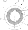
- a rib 4 is arranged on the outer circumference of the shank 2 essentially over the entire axial extent of the concrete pile element, which rib runs helically around the shank 2 and thereby forms a single-start external thread with a uniform pitch. In the figures 2 and 3 this rib 4 is not shown in section to simplify the illustration.
- the boundaries of the central opening 3 form a circular through-bore, seen in cross-section, from which two recesses 6 extend radially outwards, distributed evenly over its circumference, ie each offset by 180° on the circumference.
- the depressions 6 each have one, seen in cross section axis of symmetry Z running in the radial direction, and their lateral boundaries are each formed by a surface 9 extending essentially radially outwards.
- the drive linkage 5 has a cylindrical shaft 10 which, on its outer surface over its entire length and evenly over its circumference, i.e. offset by 180° on the circumference, has two projections 11 running in the axial direction and extending outwards in the radial direction carries, which engage in the radially outwardly extending recesses 6 in the boundaries of the central opening 3.
- the projections 11 of the drive linkage 5 are each essentially trapezoidal in cross-section, with the oblique sides of the trapezoidal shape extending along radial lines running through the center of the drive linkage 5 .
- the drive linkage 5 is then rotated to drive the concrete pile element 1 as intended, it rotates in the central opening 3 until the rotational play is achieved by the projections 11 striking the radially outwardly extending surfaces 9 of the lateral delimitations of the depressions, which are directed counter to the screwing-in direction R of the thread 6 is repealed (see figure 5 ).
- the drive torque is then transmitted from the drive linkage 5 to the concrete pile element 1 by the introduction of compressive forces running essentially perpendicularly to this surface 9 F with the projections 11 of the drive linkage 5 in these surfaces 9.
- the boundaries of the central opening 3 seen in cross-section form in the depressions 6 adjoining the respective lateral boundaries of the respective depression 6 regions 8 in which the radial extent S1, S2 of the central opening 3 decreases uniformly and steplessly in the direction of screwing in the thread R (the radial extent S1 is greater than the radial extent S2, which follows S1 in the direction of screwing in the thread R).
- the figures 6 and 7 13 show perspective views of the two swivel halves 13a, 13b which form the ends of the concrete pile element 1.
- FIG. As can be seen, the first rotary coupling half 13a is designed as a male rotary coupling half (see FIG 6 ).
- the rotary coupling formed with the rotary coupling halves 13a, 13b is a bayonet coupling with six locking points distributed evenly over the circumference of the coupling.
- the rotating coupling halves 13a, 13b are designed at the ends of the concrete pile element 1 and rotationally aligned with respect to the central opening 3 and the helical rib 4 in such a way that an intended coupling situation is possible in which the cross sections of the central openings 3 of two concrete pile elements 1 coupled together as intended are congruent are and whose helical ribs 4 form sections of a common screw thread.
- the procedure for coupling two such concrete pile elements 1 together as intended is as follows: In a first step, a first of the two concrete pile elements is screwed into a substrate using the driving tool 5, preferably in such a way that its free end is formed by the male swivel coupling half 13a.
- the end of the second concrete pile element formed by the female swivel half 13b is then abutted against the free end of the first concrete pile element, which is formed by a first swivel half 13a, in such a way that the longitudinal axes of the concrete pile elements coincide and the insertion ring 14 of the male swivel half 13a is separated from the Receiving ring 16 of the female swivel half 13b is received.
- the cross-sectional contours of the central openings 3 of the two concrete pile elements 1a, 1b are arranged rotated relative to one another by an angle of rotation ⁇ , which is larger or is equal to the angle of rotation, which is required for the intended coupling of the two rotating coupling halves 13a, 13b.
- the central openings 3 of the two concrete pile elements 1a, 1b are penetrated by the driving tool 5 in such a way that the driving tool 5 in the closing direction of rotation DS of the second swivel coupling half 13b, which forms the adjacent end of the second concrete pile 1b, forms a rotational form fit with the boundaries of the central opening 3 of the second concrete pile element 1b and such a form fit with the boundaries of the central opening 3 of the first concrete pile element 1a only occurs after the drive tool 5 has been twisted in the central opening 3 of the first screwed concrete pile element 1a by the twisting angle ⁇ , as is the case in 9 is shown.
- the second concrete pile element 1b is then rotated relative to the first concrete pile element 1a with the drive tool 5 by the twisting angle ⁇ in the closing direction of rotation DS of the second swivel joint half 13b, which forms the adjacent end of the second concrete pile 1b, whereby the two swivel joint halves 13a, 13b are coupled together as intended and the cross-sectional contours of the central openings 3 of the two concrete pile elements 1a, 1b become congruent.
- This situation is in 10 shown.
- the first concrete pile element 1a is completely hidden behind the second concrete pile element 1b in this illustration and is therefore not visible.
- the first concrete pile element 1a and the second concrete pile element 1b are used together with the driving tool 5 is screwed into the ground, with the screwing-in direction R corresponding to the locking rotating direction DS of the second rotating coupling half 13b, which forms the coupled end of the second concrete pile 1b.
- the central openings 3 of both concrete pile elements 1a, 1b are penetrated by the driving tool 5, so that the driving tool 5 forms a rotational form fit in the driving direction R both with the borders of the central opening 3 of the first concrete pile element 1a and with the borders of the central opening 3 of the second concrete pile element 1b.
Abstract
Die vorliegende Anmeldung betrifft ein Betonpfahlelement (1), bevorzugterweise zur Bildung eines Betonschraubpfahls aus mehreren Betonpfahlelementen für eine Fundation. Das Pfahlelement umfasst einen im Wesentlichen zylindrischen Schaft (2) aus Beton mit einer sich in axialer Richtung durch diesen hindurch erstreckenden zentralen Öffnung (3). Die zentrale Öffnung (3) weist über ihre gesamte Erstreckung einen im Wesentlichen gleichmässigen, nicht-kreisrunden Querschnitt auf, zur Ermöglichung eines rotatorischen Formschlusses mit einem Eindrehwerkzeug (5) zwecks Übertragung eines Drehmoments um die Längsachse (X) des Betonpfahlelements (1) herum auf das Betonpfahlelement (1). Die Enden des Betonpfahlelementes (1) sind jeweils von einer Hälfte (13a; 13b) einer Drehkupplung gebildet, derart, dass mehrere Betonpfahlelemente (1a, 1b) durch ein durch endseitiges aneinander Angrenzen und anschliessendes relatives Verdrehen zueinander um einen Verdrehwinkel bewirktes bestimmungsgemässes Zusammenkuppeln der beiden Drehkupplungshälften (13a, 13b) formschlüssig in Längsrichtung der Betonpfahlelemente (1a, 1b) miteinander verbindbar sind.The present application relates to a concrete pile element (1), preferably for forming a screwed concrete pile from a plurality of concrete pile elements for a foundation. The pile element comprises a substantially cylindrical concrete shank (2) with a central opening (3) extending axially therethrough. The central opening (3) has a substantially uniform, non-circular cross-section over its entire extent to enable a rotational form fit with a screwing tool (5) for the purpose of transmitting a torque about the longitudinal axis (X) of the concrete pile element (1). the concrete pile element (1). The ends of the concrete pile element (1) are each formed by one half (13a; 13b) of a rotary coupling, such that several concrete pile elements (1a, 1b) can be coupled together as intended by the two elements adjoining one another at the end and then rotating them relative to one another by a twisting angle Swivel coupling halves (13a, 13b) can be connected to one another in a form-fitting manner in the longitudinal direction of the concrete pile elements (1a, 1b).
Description
Die vorliegende Erfindung betrifft ein Betonpfahlelement, ein Set umfassend mindestens ein solches Betonpfahlelement und ein Eindrehwerkzeug für das Betonpfahlelement sowie ein Verfahren zum Zusammenkuppeln solcher Betonpfahlelemente gemäss den Oberbegriffen der unabhängigen Patentansprüche.The present invention relates to a concrete pile element, a set comprising at least one such concrete pile element and a screwing-in tool for the concrete pile element, and a method for coupling such concrete pile elements together, according to the preambles of the independent patent claims.
Betonschraubpfähle kommen heute zunehmend bei der Erstellung von Fundationen in Gebieten zum Einsatz, in denen die oberflächennahen Bodenschichten nur eine geringe Tragfähigkeit aufweisen. Im Gegensatz zu Rammpfählen weisen sie den Vorteil auf, dass sie erschütterungsfrei und ohne starke Lärmemissionen in den Boden eingebracht werden können. Zudem weisen sie eine grössere Tragfähigkeit auf als Rammpfähle oder Ortbetonpfähle vergleichbarer Dimensionierung.Concrete screw piles are increasingly being used to create foundations in areas where the near-surface soil layers only have a low load-bearing capacity. In contrast to driven piles, they have the advantage that they can be driven into the ground without any vibrations or excessive noise emissions. In addition, they have a greater load-bearing capacity than driven piles or in-situ concrete piles of comparable dimensions.
Aus
Die Betonpfahlelemente weisen an ihren Enden Stahlringe auf, welche nach dem aneinander Angrenzen und zueinander Ausrichten der Enden zweier aufeinanderfolgender Betonpfahlelemente umfangsmässig miteinander verschweisst werden, bevor beide Pfahlelemente zusammen weiter in den Untergrund eingedreht werden. Dies ist erforderlich, um eine dauerhafte und belastbare axiale wie radiale Verbindung zwischen den Betonpfahlelementen zu gewährleisten.The concrete pile elements have steel rings at their ends which, after adjoining and aligning the ends of two consecutive concrete pile elements, are welded together circumferentially before both pile elements are screwed further together into the ground. This is necessary to ensure a durable and resilient axial and radial connection between the concrete pile elements.
Dieses Verschweissen benötigt jedoch relativ viel Zeit, während der kein Vortrieb möglich ist, und limitiert daher die mögliche tägliche Vortriebsleistung erheblich.However, this welding requires a relatively large amount of time, during which no propulsion is possible, and therefore limits the possible daily propulsion performance considerably.
Es stellt sich deshalb die Aufgabe, technische Lösungen zur Verfügung zu stellen, welche die zuvor erwähnten Nachteile des Standes der Technik nicht aufweisen oder zumindest teilweise vermeiden.The object is therefore to provide technical solutions which do not have the aforementioned disadvantages of the prior art or at least partially avoid them.
Diese Aufgabe wird durch die Gegenstände der unabhängigen Patentansprüche gelöst.This object is solved by the subject matter of the independent patent claims.
Gemäss diesen betrifft ein erster Aspekt der Erfindung ein Betonpfahlelement, bevorzugterweise zur Bildung eines Betonschraubpfahls für eine Fundation aus mehreren anspruchsgemässen Betonpfahlelementen.According to these, a first aspect of the invention relates to a concrete pile element, preferably for forming a screwed concrete pile for a foundation made up of several concrete pile elements according to the claims.
Das Betonpfahlelement umfasst einen im Wesentlichen zylindrischen Schaft aus Beton mit einer sich in axialer Richtung durch diesen hindurch erstreckenden zentralen Öffnung. Diese zentrale Öffnung weist über ihre gesamte Längserstreckung einen im Wesentlichen gleichmässigen, nicht-kreisrunden Querschnitt auf, zur Ermöglichung eines rotatorischen Formschlusses mit einem Eindrehwerkzeug zwecks Übertragung eines Drehmoments um die Längsachse des Betonpfahlelements herum auf dieses.The concrete pile element comprises a substantially cylindrical concrete shank having a central opening extending axially therethrough. This central opening has a substantially uniform, non-circular cross-section over its entire length, to enable a rotary form fit with a screwing-in tool for the purpose of transmitting a torque around the longitudinal axis of the concrete pile element to the latter.
Die Enden des Betonpfahlelementes sind jeweils von einer Hälfte einer Drehkupplung gebildet, derart, dass mehrere dieser Betonpfahlelemente durch ein durch endseitiges aneinander Angrenzen und anschliessendes relatives Verdrehen zueinander um einen Verdrehwinkel bewirktes bestimmungsgemässes Zusammenkuppeln der beiden Drehkupplungshälften formschlüssig in Längsrichtung der Betonpfahlelemente miteinander verbunden werden können.The ends of the concrete pile element are each formed by one half of a swivel joint, such that several of these concrete pile elements can be positively connected to one another in the longitudinal direction of the concrete pile elements by coupling the two swivel joint halves together as intended by adjoining one another at the ends and then rotating them relative to one another by a twisting angle.
Durch diese erfindungsgemässe Ausgestaltung der Betonpfahlelemente wird es möglich, beim Erstellen einer Schraubpfahl-Fundation aus mehreren hintereinander angeordneten Betonpfahlelementen die Pfahlelemente beim Einbringen in den Boden in kürzester Zeit sicher miteinander zu verbinden und dadurch die tägliche Vortriebsleistung deutlich zu steigern.This design of the concrete pile elements according to the invention makes it possible, when creating a screw pile foundation from several concrete pile elements arranged one behind the other, to securely connect the pile elements to one another in the shortest possible time when they are introduced into the ground, thereby significantly increasing the daily driving performance.
Dabei können die beiden Drehkupplungshälften identisch ausgebildet sein, oder aber eine erste der beiden Drehkupplungshälften kann als männliche Drehkupplungshälfte ausgebildet sein und die zweite Drehkupplungshälfte als dazu komplementäre weibliche Drehkupplungshälfte. Im erstgenannten Fall ergibt sich der Vorteil, dass jedes Ende des erfindungsgemässen Betonpfahlelements mit jedem Ende eines weiteren entsprechenden Betonschraubpfahls kuppelbar ist. Im letztgenannten Fall ergibt sich der Vorteil, dass am jeweils nach oben zeigenden Ende eine Drehkupplungshälfte gewählt werden kann, welche weniger anfällig für Verschmutzungen ist bzw. vor dem Kuppeln einfacher gereinigt werden kann, was typischerweise auf eine männliche Drehkupplungshälfte zutrifft.The two rotary coupling halves can be designed identically, or a first of the two rotary coupling halves can be designed as a male rotary coupling half be formed and the second rotary coupling half as a complementary female rotary coupling half. In the former case, there is the advantage that each end of the concrete pile element according to the invention can be coupled to each end of a further corresponding concrete screw pile. In the latter case, there is the advantage that a rotary coupling half can be selected at the end pointing upwards, which is less susceptible to dirt or can be cleaned more easily before coupling, which typically applies to a male rotary coupling half.
Die Drehkupplungshälften sind mit Vorteil derartig ausgebildet, dass sie nach einem bestimmungsgemässen Zusammenkuppeln formschlüssig gegen ein Verdrehen relativ zueinander gesichert werden können, bevorzugterweise mit einem Riegelelement, welches hierzu in dafür vorgesehene Aufnahmen an den Drehkupplungshälften eingesetzt werden kann. Auf diese Weise kann die Kupplung zweier erfindungsgemässer Betonpfahlelemente in kürzester Zeit gegen ein unbeabsichtigtes Öffnen gesichert werden.The rotary coupling halves are advantageously designed in such a way that they can be positively secured against twisting relative to one another after they have been coupled together as intended, preferably with a locking element which can be inserted into receptacles provided for this purpose on the rotary coupling halves. In this way, the coupling of two concrete pile elements according to the invention can be secured against unintentional opening in a very short time.
In einer bevorzugten Ausführungsform sind die beiden Drehkupplungshälften als Hälften einer Bajonett-Kupplung ausgebildet, welche bevorzugterweise mehrere gleichmässig über den Umfang der Kupplung verteilte Verriegelungsstellen aufweist. Derartige Bajonett-Kupplungen sind robust und einfach zu kuppeln.In a preferred embodiment, the two rotary coupling halves are designed as halves of a bayonet coupling, which preferably has a plurality of locking points distributed evenly over the circumference of the coupling. Such bayonet couplings are robust and easy to couple.
Mit Vorteil sind die Drehkupplungshälften an den Enden des Betonpfahlelementes rotatorisch derartig bezüglich der zentralen Öffnung ausgerichtet, dass mindestens eine bestimmungsgemässe Kupplungssituation möglich ist, in welcher die Querschnitte der zentralen Öffnungen zweier bestimmungsgemäss zusammengekuppelter Betonpfahlelemente deckungsgleich sind. Dabei ist es weiter bevorzugt, dass die Drehkupplungshälften an den Enden des Betonpfahlelementes derartig ausgebildet und rotatorisch derartig bezüglich der zentralen Öffnung ausgerichtet sind, dass ein bestimmungsgemässes Zusammenkuppeln zweier solcher Betonpfahlelemente zwangsläufig zu einer Situation führt, in welcher die Querschnitte der zentralen Öffnungen der gekuppelten Betonpfahlelemente deckungsgleich sind. Hierdurch wird es möglich, die zentralen Öffnungen sämtlicher miteinander gekuppelter Betonpfahlelemente mit einem Eindrehwerkzeug gleichzeitig zu durchsetzen und entsprechend sämtliche miteinander gekuppelten Betonpfahlelemente direkt mit dem Eindrehwerkzeug anzutreiben.Advantageously, the rotary coupling halves at the ends of the concrete pile element are rotationally aligned with respect to the central opening such that at least one intended coupling situation is possible in which the cross sections of the central openings of two concrete pile elements coupled together as intended are congruent. It is further preferred that the rotary coupling halves are designed in such a way at the ends of the concrete pile element and aligned rotationally in this way with respect to the central opening are that an intended coupling together of two such concrete pile elements inevitably leads to a situation in which the cross sections of the central openings of the coupled concrete pile elements are congruent. This makes it possible to push through the central openings of all the concrete pile elements that are coupled to one another with a driving tool at the same time, and accordingly to drive all the concrete pile elements that are coupled to one another directly with the driving tool.
In einer ersten bevorzugten Ausführungsvariante weist der Schaft des Betonpfahlelements eine im Wesentlichen glatte Aussenfläche auf.In a first preferred embodiment variant, the shank of the concrete pile element has an essentially smooth outer surface.
In einer zweiten, alternativen bevorzugten Ausführungsvariante weist der Schaft des Betonpfahlelements an seinem Aussenumfang zumindest über einen Teilbereich seiner axialen Erstreckung eine oder mehrere Rippen auf, welche schraubenförmig über seine Aussenfläche verlaufen und dabei ein eingängiges oder mehrgängiges Aussengewinde bilden. Dabei ist die Steigung des von den Rippen gebildeten Gewindes bevorzugterweise gleichmässig.In a second, alternative preferred embodiment, the shank of the concrete pile element has one or more ribs on its outer circumference at least over a partial area of its axial extent, which run helically over its outer surface and thereby form a single-start or multiple-start external thread. The pitch of the thread formed by the ribs is preferably uniform.
Die erste, glatte Ausführungsvariante von Betonpfahlelementen kommt bei der Erstellung von Betonschraubpfählen immer in Kombination mit der zweiten Ausführungsvariante mit Schraubgewinde zum Einsatz und wird z.B. zur Überbrückung von Bodenschichten eingesetzt, welche wenig tragfähig sind oder Setzungen unterworfen sind. Bei derartigen Bodenschichten ergibt ein formschlüssiger Eingriff über ein Schraubengewinde im erstgenannten Fall kaum eine Verbesserung der Tragfähigkeit und verringert die Tragfähigkeit im letztgenannten Fall sogar, weil derartige Setzungen mit der Zeit zu einer zusätzlichen Belastung des Betonschraubpfahles führen würden.The first, smooth design variant of concrete pile elements is always used in combination with the second design variant with screw thread when creating concrete screw piles and is used, for example, to bridge soil layers that are not very stable or are subject to settlement. With such soil layers, a form-fitting engagement via a screw thread in the former case hardly improves the load-bearing capacity and even reduces the load-bearing capacity in the latter case, because such settlements would lead to additional stress on the concrete screw pile over time.
Bei der zweiten, alternativen Ausführungsvariante mit schraubenförmigen Rippen am Schaft weist die zentrale Öffnung über ihre gesamte Erstreckung einen im Wesentlichen gleichmässigen, nicht-kreisrunden Querschnitt auf, derart, dass sie einen rotatorischen Formschluss mit einem Eindrehwerkzeug zwecks Übertragung eines Drehmoments auf das Betonpfahlelement um dessen Längsachse herum in der bestimmungsgemässen Gewindeeindrehrichtung ermöglicht.In the second, alternative embodiment variant with helical ribs on the shaft, the central opening has a substantially uniform, non-circular cross-section over its entire extent, such that it has a rotational form fit with a screwing tool for the purpose of transmitting a torque to the concrete pile element around its longitudinal axis in the intended screwing-in direction.
Mit Vorteil sind dabei die Drehkupplungshälften an den Enden des Betonpfahlelementes derartig ausgebildet und rotatorisch derartig bezüglich der schraubenförmigen Rippen der Aussenfläche des Schafts ausgerichtet, dass mindestens eine bestimmungsgemässe Kupplungssituation möglich ist, in welcher die schraubenförmigen Rippen zweier bestimmungsgemäss zusammengekuppelter solcher Betonpfahlelemente Abschnitte eines gemeinsamen Schraubengewindes bilden. Noch bevorzugter sind die Drehkupplungshälften an den Enden des Betonpfahlelementes derartig ausgebildet und rotatorisch derartig bezüglich der schraubenförmigen Rippen der Aussenfläche des Schafts ausgerichtet, dass das bestimmungsgemässe Zusammenkuppeln zweier derartiger Betonpfahlelemente zwangsläufig zu einer Situation führt, in welcher die schraubenförmigen Rippen der gekuppelten Betonpfahlelemente Abschnitte eines gemeinsamen Schraubengewindes bilden. Hierdurch kann sichergestellt werden, dass beim Einschrauben in den Boden von mehreren miteinander gekuppelten Betonpfahlelementen mit schraubenförmigen Rippen am Schaft die auf das erste dieser Betonpfahlelemente folgenden Betonpfahlelemente mit ihren schraubenförmigen Rippen dem durch die Rippen des ersten Betonpfahlelement geformten Gewinde im Boden folgen und dieses nicht zerstören, was sonst zu einem weitestgehenden Verlust der Tragfähigkeit der folgenden Betonpfahlelementen führen würde.Advantageously, the swivel coupling halves at the ends of the concrete pile element are designed in such a way and are rotationally aligned in relation to the helical ribs on the outer surface of the shaft in such a way that at least one intended coupling situation is possible in which the helical ribs of two such concrete pile elements coupled together as intended form sections of a common screw thread. More preferably, the rotary coupling halves at the ends of the concrete pile element are configured and rotationally aligned with respect to the helical ribs of the outer surface of the shank such that the intended coupling together of two such concrete pile elements necessarily leads to a situation in which the helical ribs of the coupled concrete pile elements share sections of a common screw thread form. In this way it can be ensured that when several concrete pile elements coupled to one another with helical ribs on the shaft are screwed into the ground, the concrete pile elements following the first of these concrete pile elements with their helical ribs follow the thread in the ground formed by the ribs of the first concrete pile element and do not destroy it, which would otherwise lead to the greatest possible loss of load-bearing capacity of the following concrete pile elements.
Auch ist es bei der zweiten, alternativen Ausführungsvariante des Betonpfahlelements mit schraubenförmigen Rippen am Schaft bevorzugt, dass die Begrenzungen der zentralen Öffnung im Querschnitt gesehen mehrere sich radial nach aussen erstreckende Vertiefungen aufweisen, deren entgegen der bestimmungsgemässen Gewindeeindrehrichtung gerichtete seitliche Begrenzungen jeweils von einer sich im Wesentlichen radial nach aussen erstreckende Fläche gebildet sind oder eine solche Fläche aufweisen, zur Einleitung einer im Wesentlichen senkrecht zu dieser Fläche verlaufende Druckkraft mit dem Eindrehwerkzeug in diese Fläche für die Übertragung des Drehmoments in Gewindeeindrehrichtung vom Eindrehwerkzeug auf das Betonpfahlelement. Diese Vertiefungen sind bevorzugterweise identisch ausgebildet und mit Vorteil gleichmässig über den Umfang der zentralen Öffnung verteilt.In the second, alternative embodiment variant of the concrete pile element with helical ribs on the shaft, it is also preferred that the boundaries of the central opening, viewed in cross section, have several radially outwardly extending depressions, the lateral boundaries of which are directed counter to the intended screwing-in direction of the thread are formed by a surface extending essentially radially outwards or have such a surface, for introducing a compressive force running essentially perpendicularly to this surface with the driving tool into this surface for the transmission of the torque in the thread driving direction from the driving tool to the concrete pile element. These indentations are preferably of identical design and are advantageously distributed evenly over the circumference of the central opening.
Weiter weisen die Begrenzungen der zentralen Öffnung im Querschnitt gesehen an mehreren gleichmässig über ihren Umfang verteilten Stellen Bereiche auf, in denen die radiale Erstreckung der zentralen Öffnung von ihrem Zentrum gesehen in Gewindeeindrehrichtung abnimmt, und zwar bevorzugterweise stufenlos und bevorzugterweise gleichmässig. Durch diese Ausbildung der zentralen Öffnung wird es möglich, durch eine geeignete Ausbildung der in diese einzuführenden Kontur des Eindrehwerkzeugs eine radiale Selbstzentrierung des Eindrehwerkzeugs in der zentralen Öffnung des Betonpfahlelements beim bestimmungsgemässen Einschrauben zu erzielen.Viewed in cross-section, the boundaries of the central opening also have areas at several points evenly distributed over its circumference, in which the radial extension of the central opening, viewed from its center, decreases in the screwing-in direction, preferably steplessly and preferably evenly. This design of the central opening makes it possible to achieve radial self-centering of the driving tool in the central opening of the concrete pile element when screwing in as intended, by suitably designing the contour of the screwing tool to be inserted into it.
Bevorzugterweise liegen die Bereiche, in denen die radiale Erstreckung der zentralen Öffnung in Gewindeeindrehrichtung abnimmt, in den sich radial nach aussen erstreckenden Vertiefungen. Hierdurch wird es möglich, die Selbstzentrierung des Eindrehwerkzeugs über dieselben Konturen des Eindrehwerkzeugs zu erzielen, welche auch der Übertragung der Antriebskraft dienen, so dass einfache und kostengünstig herstellbare Eindrehwerkzeug-Geometrien möglich werden.Preferably, the areas in which the radial extent of the central opening decreases in the screwing-in direction are in the radially outwardly extending depressions. This makes it possible to achieve the self-centering of the driving tool using the same contours of the driving tool that also serve to transmit the drive force, so that simple driving tool geometries that can be produced cost-effectively become possible.
Dabei ist es weiter von Vorteil, dass die Bereiche, in denen die radiale Erstreckung der zentralen Öffnung in Gewindeeindrehrichtung abnimmt, jeweils an die seitliche Begrenzung der Vertiefungen angrenzen, welche von der sich im Wesentlichen radial nach aussen erstreckende Fläche gebildet ist oder diese Fläche aufweist. Hierdurch wird die umfangsmässige Erstreckung der sich radial nach aussen erstreckenden Vertiefungen durch die darin angeordneten Bereiche, in denen die radiale Erstreckung der zentralen Öffnung in Gewindeeindrehrichtung abnimmt, praktisch nicht beeinflusst.It is also advantageous that the areas in which the radial extent of the central opening decreases in the screwing-in direction of the thread adjoin the lateral delimitation of the depressions, which is formed by the surface extending essentially radially outwards or has this surface. As a result, the circumferential extension of itself radially outwardly extending depressions by the areas arranged therein, in which the radial extent of the central opening decreases in the screwing-in direction of the thread, is practically unaffected.
Weiter ist es bevorzugt, dass die sich radial nach aussen erstreckenden Vertiefungen gleichmässig über den Umfang der zentralen Öffnung verteilt sind. Hierdurch kann eine umfangsmässig gleichmässige Einleitung der Antriebskräfte in das Betonpfahlelement erreicht werden.Furthermore, it is preferred that the depressions extending radially outwards are distributed uniformly over the circumference of the central opening. In this way, the drive forces can be introduced into the concrete pile element evenly over the circumference.
Dabei ist es weiter bevorzugt, dass die Begrenzungen der zentralen Öffnung im Querschnitt gesehen genau zwei, mit Vorteil identisch ausgebildete, sich radial nach aussen erstreckende Vertiefungen aufweisen, welche bevorzugterweise gleichmässig über ihren Umfang verteilt angeordnet sind. Durch diese Ausbildungen wird eine definierte und gleichmässige Belastung der die Antriebskräfte übertragenden Flächen der Begrenzungen der zentralen Öffnung begünstigt.It is further preferred that the delimitations of the central opening, seen in cross-section, have exactly two, advantageously identically designed, radially outwardly extending depressions, which are preferably distributed evenly over their circumference. A defined and uniform loading of the surfaces of the delimitations of the central opening, which transmit the driving forces, is promoted by this configuration.
Bei einer weiteren bevorzugten Ausführungsform des Betonpfahlelements weisen die sich radial nach aussen erstreckenden Vertiefungen im Querschnitt gesehen jeweils eine in radialer Richtung verlaufende Symmetrieachse auf. Derartige Betonpfahlelemente können mit dem gleichen Eindrehwerkzeug wahlweise mit dem einen oder mit dem anderen Ende voraus eingedreht werden und bei Bedarf auch wieder herausgedreht werden.In a further preferred embodiment of the concrete pile element, the radially outwardly extending depressions, viewed in cross section, each have an axis of symmetry running in the radial direction. Such concrete pile elements can be screwed in with the same screwing-in tool either with one or the other end first and, if necessary, also be screwed out again.
Das von den Rippen am Schaft des Betonpfahlelements gebildete Aussengewinde erstreckt sich bevorzugterweise im Wesentlichen über die gesamte Länge des Schafts, wobei an den Enden des Betonpfahlelements kurze gewindefreie Bereiche vorliegen können. Derartige Betonpfahlelemente, bei denen der Schaft praktisch über seine gesamte Länge mit dem Gewinde überzogen ist, weisen im bestimmungsgemäss eingebauten Zustand eine besonders hohe Tragfähigkeit auf.The external thread formed by the ribs on the shank of the concrete pile element preferably extends essentially over the entire length of the shank, it being possible for there to be short unthreaded areas at the ends of the concrete pile element. Concrete pile elements of this type, in which the shank is covered with the thread practically over its entire length, have a particularly high load-bearing capacity when installed as intended.
Die das Gewinde am Schaft des Betonpfahlelements bildenden Rippen sind bevorzugterweise aus Beton gebildet, z.B. indem sie bei der Herstellung des Betonpfahlelements mittels einer Aussenform ausgeformt wurden. Derartige Betonpfahlelemente weisen gegenüber Ausführungsformen, bei denen diese Rippen durch einbetonierte Metallelemente gebildet werden, einen deutlichen Kostenvorteil auf. Zudem besteht hier nicht die Gefahr, dass es beim installierten Betonpfahlelement mit der Zeit zu einem schleichenden Tragfähigkeitsverlust durch korrosive Zerstörung der Gewinderippen kommt.The ribs forming the threads on the shank of the concrete pile element are preferably made of concrete formed, for example by being formed in the manufacture of the concrete pile element by means of an outer mold. Concrete pile elements of this type have a clear cost advantage over embodiments in which these ribs are formed by metal elements embedded in concrete. In addition, there is no risk of the installed concrete pile element gradually losing its load-bearing capacity over time due to corrosive destruction of the thread ribs.
Die Begrenzungen der zentralen Öffnung sind ebenfalls bevorzugterweise aus Beton gebildet, z.B. indem sie bei der Herstellung des Betonpfahlelements mittels eines Formkerns ausgeformt wurden. Derartige Betonpfahlelemente weisen gegenüber Ausführungsformen, bei denen die Begrenzungen der zentralen Öffnung durch ein in das Betonpfahlelement einbetoniertes Metallprofil gebildet werden, einen deutlichen Kostenvorteil auf.The boundaries of the central opening are also preferably formed of concrete, for example by being formed from a mandrel during manufacture of the concrete pile element. Such concrete pile elements have a clear cost advantage over embodiments in which the delimitations of the central opening are formed by a metal profile concreted into the concrete pile element.
Ein zweiter Aspekt der Erfindung betrifft ein Set umfassend mindestens ein Betonpfahlelement gemäss dem ersten Aspekt der Erfindung und ein Eindrehwerkzeug, mit welchem die zentrale Öffnung des Betonpfahlelements durchsetzt werden kann und ein rotatorischer Formschluss mit den Begrenzungen der zentralen Öffnung erzeugt werden kann, zur Übertragung eines Drehmoments um die Längsachse des Betonpfahlelements herum von dem Eindrehwerkzeug auf das Betonpfahlelement. Dabei ist das Eindrehwerkzeug derartig ausgebildet, dass es in der zentralen Öffnung des Betonpfahlelements gegenüber dem Betonpfahlelement um einen Winkel verdreht werden kann, welcher gleich gross oder grösser ist als der Verdrehwinkel, welcher benötigt würde zum bestimmungsgemässen Zusammenkuppeln der beiden Drehkupplungshälften des Betonpfahlelements. Durch diese Ausgestaltung der zentralen Öffnung des Betonpfahlelements und des Eindrehwerkzeug ist es möglich, die zentralen Öffnungen sämtlicher bereits miteinander gekuppelter und schon in den Boden eingeschraubter Betonpfahlelemente sowie die zentrale Öffnung des anzukuppelnden Betonpfahlelements mit dem Eindrehwerkzeug gleichzeitig zu durchsetzen und das anzukuppelnde Betonpfahlelement sodann mit dem Eindrehwerkzeug gegenüber den bereits miteinander gekuppelten und schon in den Boden eingeschraubten Betonpfahlelementen zu verdrehen und dadurch an diese anzukuppeln.A second aspect of the invention relates to a set comprising at least one concrete pile element according to the first aspect of the invention and a screwing-in tool, with which the central opening of the concrete pile element can be penetrated and a rotational form fit with the limitations of the central opening can be generated for the transmission of a torque around the longitudinal axis of the concrete pile element from the driving tool onto the concrete pile element. The screwing-in tool is designed in such a way that it can be rotated in the central opening of the concrete pile element relative to the concrete pile element by an angle which is equal to or greater than the angle of rotation which would be required for the intended coupling of the two rotary coupling halves of the concrete pile element. This configuration of the central opening of the concrete pile element and the screwing-in tool makes it possible to use the central openings of all concrete pile elements already coupled to one another and already screwed into the ground, as well as the central opening of the concrete pile element to be coupled to push through with the screwing-in tool at the same time and then to twist the concrete pile element to be coupled with the screwing-in tool in relation to the concrete pile elements already coupled to one another and already screwed into the ground and thereby to couple it to them.
Mit Vorteil ist das mindestens eine Betonpfahlelement als Betonpfahlelement mit schraubenförmigen Rippen am Schaft ausgebildet und das Eindrehwerkzeug weist einen zylindrischen Schaft auf, welcher an seiner Aussenfläche, bevorzugterweise über seine gesamte Länge, in axialer Richtung verlaufende und sich in radialer Richtung nach aussen hin erstreckende Vorsprünge trägt. Diese Vorsprünge können durch axiales Einschieben des Eindrehwerkzeugs in die zentrale Öffnung des Betonpfahlelements in den radial sich nach aussen erstreckenden Vertiefungen der Begrenzungen der zentralen Öffnung angeordnet werden, derart, dass mit ihnen unter einer Rotation des Eindrehwerkzeugs in Gewindeeindrehrichtung eine im Wesentlichen senkrecht zu den im Wesentlichen radial nach aussen sich erstreckenden Flächen der Vertiefungen verlaufende Druckkraft in diese Flächen eingeleitet werden kann, zur Übertragung eines Drehmoments um die Längsachse des Betonpfahlelements herum vom Eindrehwerkzeug auf das Betonpfahlelement.The at least one concrete pile element is advantageously designed as a concrete pile element with helical ribs on the shank, and the driving tool has a cylindrical shank which, on its outer surface, preferably over its entire length, carries projections running in the axial direction and extending outwards in the radial direction . By axially pushing the screwing tool into the central opening of the concrete pile element, these projections can be arranged in the radially outwardly extending depressions of the boundaries of the central opening in such a way that, when the screwing tool is rotated in the screwing-in direction, a substantially perpendicular to the substantially A compressive force extending radially outwards from the surfaces of the depressions can be introduced into these surfaces in order to transmit a torque about the longitudinal axis of the concrete pile element from the driving tool to the concrete pile element.
Dabei ist das Eindrehwerkzeug bevorzugterweise derartig ausgebildet, dass es mit radialem Spiel in die zentrale Öffnung des Betonschraubpfahlelements eingeführt werden kann und dass bei einem anschliessenden Verdrehen des eingeführten Eindrehwerkzeugs in Einschraubrichtung das radiale Spiel durch eine Annäherung von radialen Begrenzungen des Eindrehwerkzeugs an die Begrenzungen der zentralen Öffnung in den Bereichen, in denen die radiale Erstreckung der zentralen Öffnung in Gewindeeindrehrichtung bevorzugterweise stufenlos abnimmt, verringert oder aufgehoben wird.The driving tool is preferably designed in such a way that it can be inserted with radial play into the central opening of the concrete screw pile element and that when the inserted driving tool is subsequently rotated in the screwing-in direction, the radial play is compensated for by the radial limits of the driving tool approaching the limits of the central opening in the areas in which the radial extent of the central opening in the screwing-in direction preferably continuously decreases, is reduced or eliminated.
Durch diese Ausgestaltung der zentralen Öffnung des Betonpfahlelements und des Eindrehwerkzeugs kann das Eindrehwerkzeug mit ausreichendem Spiel problemlos in die zentrale Öffnung des Betonpfahlelements eingeführt werden und zentriert sich beim anschliessenden Eindrehen des Betonpfahlelements selbsttätig gegenüber dem Betonpfahlelement, ohne dass dieses mit nennenswerten radialen Spreizkräften beaufschlagt wird.This design of the central opening of the concrete pile element and the screwing-in tool allows the screwing-in tool to be inserted into the central opening of the concrete pile element with sufficient play without any problems and, when the concrete pile element is subsequently screwed in, automatically centers itself in relation to the concrete pile element, without this being subjected to appreciable radial expansion forces.
Dabei ist es weiter bevorzugt, dass das Betonpfahlelement und das Eindrehwerkzeug derartig ausgebildet sind, dass das radiale Spiel durch eine Annäherung der radialen Begrenzungen der Vorsprünge des Eindrehwerkzeugs an in den Vertiefungen angeordnete Bereiche der Begrenzungen der zentralen Öffnung, in denen die radiale Erstreckung der zentralen Öffnung in Gewindeeindrehrichtung bevorzugterweise stufenlos abnimmt, verringert oder aufgehoben wird. Hierdurch wird es möglich, die Selbstzentrierung des Eindrehwerkzeugs über dieselben Konturen des Eindrehwerkzeugs zu erzielen, welche auch der Übertragung der Antriebskraft dienen, wodurch einfache und kostengünstig herstellbare Eindrehwerkzeug-Geometrien möglich sind.It is further preferred that the concrete pile element and the driving tool are designed in such a way that the radial play is reduced by bringing the radial limits of the projections of the driving tool closer to areas of the limits of the central opening which are arranged in the depressions and in which the radial extent of the central opening decreases, is reduced or eliminated in the direction of screwing-in of the thread, preferably steplessly. This makes it possible to achieve the self-centering of the driving tool using the same contours of the driving tool that also serve to transmit the driving force, as a result of which simple driving tool geometries that can be produced at low cost are possible.
Weiter ist es bevorzugt, dass das Betonpfahlelement und das Eindrehwerkzeug derartig ausgebildet sind, dass sich das Eindrehwerkzeug im bestimmungsgemäss in die zentrale Öffnung des Betonpfahlelements eingeführten Zustand über die gesamte Länge der zentralen Öffnung erstreckt. Hierdurch wird eine Krafteinleitung in den Betonpfahlelement über die gesamte Länge der zentralen Öffnung möglich.It is further preferred that the concrete pile element and the screwing-in tool are designed in such a way that the screwing-in tool extends over the entire length of the central opening when inserted as intended into the central opening of the concrete pile element. This allows force to be introduced into the concrete pile element over the entire length of the central opening.
Weisen die sich in radialer Richtung nach aussen hin erstreckenden Vorsprünge des Eindrehwerkzeugs jeweils einen im Wesentlichen trapezförmigen Querschnitt auf, wobei die schrägen Seiten der Trapezform sich entlang von durch das Zentrum des Eindrehwerkzeugs verlaufenden Radiallinien erstrecken, so ergibt sich bei entsprechender Ausgestaltung der Begrenzungen der zentralen Öffnung des Betonpfahlelements eine besonderes vorteilhafte Krafteinleitung in das Betonpfahlelement. Auch ergibt sich dann die Möglichkeit, das Betonpfahlelement mit dem Eindrehwerkzeug wahlweise mit dem einen oder dem anderen Ende voraus einzudrehen sowie dieses bei Bedarf auch wieder herauszudrehen.If the projections of the driving tool, which extend outwards in the radial direction, each have an essentially trapezoidal cross-section, with the oblique sides of the trapezoidal shape extending along radial lines running through the center of the driving tool, the central Opening of the concrete pile element a particularly advantageous introduction of force into the concrete pile element. There is then also the possibility of screwing in the concrete pile element with the screwing-in tool either with one end or the other in front and, if necessary, screwing it out again.
In einer weiteren bevorzugten Ausführungsform umfasst das Set Betonpfahlelemente sowohl mit schraubenförmigen Rippen am Schaft als auch mit glattem Schaft.In another preferred embodiment, the set includes concrete pile elements with both helical ribs on the shank and with a smooth shank.
Ein dritter Aspekt der Erfindung betrifft ein Verfahren zum bestimmungsgemässen Zusammenkuppeln zweier Betonpfahlelemente gemäss dem ersten Aspekt der Erfindung, welche zumindest bezüglich ihrer zentralen Öffnungen und ihrer endseitigen Drehkupplungshälften identisch ausgestaltet sind. Diese werden zusammen mit einem Eindrehwerkzeug als Set gemäss dem zweiten Aspekt der Erfindung bereitgestellt.A third aspect of the invention relates to a method for the intended coupling together of two concrete pile elements according to the first aspect of the invention, which are designed identically at least with regard to their central openings and their rotary coupling halves at the ends. These are provided together with a screwing tool as a set according to the second aspect of the invention.
In einem ersten Schritt wird ein erstes der beiden Betonpfahlelemente mit dem Eindrehwerkzeug in einen Untergrund eingedreht.In a first step, a first of the two concrete pile elements is screwed into a substrate with the screwing tool.
Sodann wird das zweite Betonpfahlelement mit der an seinem Ende angeordneten Drehkupplungshälfte an die am freien Ende des ersten Betonpfahlelementes angeordnete zugehörige Drehkupplungshälfte angegrenzt, derart, dass die Längsachsen der Betonpfahlelemente zusammenfallen und die Querschnittskonturen der zentralen Öffnungen der beiden Betonpfahlelemente entgegen der Verschliessdrehrichtung der Drehkupplungshälfte des zweiten Betonpfahlelements um einen Verdrehwinkel relativ zueinander verdreht sind, welcher grösser oder gleich dem Verdrehwinkel ist, welcher benötigt wird zum bestimmungsgemässen Zusammenkuppeln der beiden Drehkupplungshälften.Then the second concrete pile element with the swivel joint half arranged at its end is adjacent to the associated swivel joint half arranged at the free end of the first concrete pile element in such a way that the longitudinal axes of the concrete pile elements coincide and the cross-sectional contours of the central openings of the two concrete pile elements counter to the locking direction of rotation of the swivel joint half of the second concrete pile element are rotated relative to one another by an angle of rotation which is greater than or equal to the angle of rotation which is required for coupling the two rotary coupling halves together as intended.
Anschliessend werden die zentralen Öffnungen der beiden Betonpfahlelemente mit dem Eindrehwerkzeug durchsetzt, derart, dass das Eindrehwerkzeug in Verschliessdrehrichtung der Drehkupplungshälfte des zweiten Betonpfahlelements einen rotatorischen Formschluss mit den Begrenzungen der zentralen Öffnung des zweiten Betonpfahlelements bildet und ein ebensolcher Formschluss mit den Begrenzungen der zentralen Öffnung des ersten Betonpfahlelements erst nach einem Verdrehen des Antriebswerkzeug in der zentralen Öffnung des ersten Betonschraubpfahlelements um einen Verdrehwinkel vorliegt, welcher benötigt wird zum bestimmungsgemässen Zusammenkuppeln der beiden Drehkupplungshälften.Then the central openings of the two concrete pile elements are penetrated with the screwing tool in such a way that the screwing tool creates a rotational form fit in the closing direction of rotation of the rotary coupling half of the second concrete pile element forms the boundaries of the central opening of the second concrete pile element and such a form fit with the boundaries of the central opening of the first concrete pile element is only present after the drive tool has been rotated in the central opening of the first screwed concrete pile element by an angle of rotation, which is required for the intended coupling of the two rotary coupling halves.
Schliesslich wird das zweite Betonpfahlelement gegenüber dem ersten Betonpfahlelement mit dem Antriebswerkzeug in der Verschliessdrehrichtung der Drehkupplungshälfte des zweiten Betonpfahlelements um den Verdrehwinkel, welcher benötigt wird zum bestimmungsgemässen Zusammenkuppeln der beiden Drehkupplungshälften, verdreht, so dass die beiden Drehkupplungshälften bestimmungsgemäss miteinander zusammengekuppelt werden und die Querschnittskonturen der zentralen Öffnungen der beiden Betonpfahlelemente deckungsgleich werden.Finally, the second concrete pile element is twisted relative to the first concrete pile element with the drive tool in the locking direction of rotation of the swivel joint half of the second concrete pile element by the twisting angle which is required for coupling the two swivel joint halves together as intended, so that the two swivel joint halves are coupled together as intended and the cross-sectional contours of the central ones openings of the two concrete pile elements are congruent.
Durch dieses erfindungsgemässe Verfahren wird es möglich, beim Erstellen einer Fundation aus mehreren hintereinander angeordneten Betonpfahlelementen die Pfahlelemente beim Einbringen in den Boden in kürzester Zeit sicher miteinander zu Verbinden und dadurch die tägliche Vortriebsleistung deutlich zu steigern.This method according to the invention makes it possible, when creating a foundation from several concrete pile elements arranged one behind the other, to securely connect the pile elements to one another in the shortest possible time when they are being introduced into the ground, thereby significantly increasing the daily driving performance.
In einer bevorzugten Ausführungsform des Verfahrens ist zumindest eines der beiden zu kuppelnden Betonpfahlelemente ein Betonpfahlelement mit schraubenförmigen Rippen am Schaft und die Verschliessdrehrichtung der Drehkupplungshälfte des zweiten Betonpfahlelements entspricht der Gewindeeindrehrichtung des Betonpfahlelements mit den schraubenförmigen Rippen am Schaft.In a preferred embodiment of the method, at least one of the two concrete pile elements to be coupled is a concrete pile element with helical ribs on the shank and the locking direction of rotation of the rotary coupling half of the second concrete pile element corresponds to the screwing-in direction of the thread of the concrete pile element with the helical ribs on the shank.
Mit Vorteil werden die bestimmungsgemäss zusammengekuppelten Drehkupplungshälften stoffschlüssig und/oder formschlüssig gegen ein Öffnen der Kupplung durch Verdrehen relativ zueinander gesichert, bevorzugterweise mit einer Schweissverbindung oder einem Riegelelement, welches in dafür vorgesehene Aufnahmen an den Drehkupplungshälften eingesetzt wird. Auf diese Weise kann die Kupplung der Betonpfahlelemente in kürzester Zeit gegen ein unbeabsichtigtes Öffnen gesichert werden.Advantageously, the intended coupled together rotary coupling halves are materially and / or positively secured against opening of the coupling by twisting relative to each other, preferably with a welded joint or a locking element, which is provided in receptacles on the Swivel coupling halves is used. In this way, the coupling of the concrete pile elements can be secured against unintentional opening in the shortest possible time.
In einer weiteren bevorzugten Ausführungsform des Verfahrens werden das erste und das zweite Betonpfahlelement nach dem bestimmungsgemässen Zusammenkuppeln gemeinsam mit dem Eindrehwerkzeug in den Untergrund eingedreht.In a further preferred embodiment of the method, the first and the second concrete pile element are screwed into the ground together with the screwing-in tool after they have been coupled together as intended.
Dabei ist es bevorzugt, dass beim gemeinsamen Eindrehen der Betonpfahlelemente deren zentrale Öffnungen von dem Eindrehwerkzeug durchsetzt sind, derart, dass das Eindrehwerkzeug in Eindrehrichtung einen rotatorischen Formschluss sowohl mit den Begrenzungen der zentralen Öffnung des ersten Betonpfahlelements bildet als auch mit den Begrenzungen der zentralen Öffnung des zweiten Betonpfahlelements. Auf diese Weise wird eine Torsionsbeanspruchung der Betonpfahlelemente, welche zu einem Bruch führen könnte, verhindert und jedes Betonpfahlelement wird nur mit dem Drehmoment beaufschlagt, welches es selbst für die Eindrehbewegung benötigt.It is preferred that when the concrete pile elements are screwed in together, the screwing tool passes through their central openings in such a way that the screwing tool forms a rotational form fit in the screwing-in direction both with the borders of the central opening of the first concrete pile element and with the borders of the central opening of the second concrete pile element. In this way, a torsional stress on the concrete pile elements, which could lead to breakage, is prevented and each concrete pile element is only subjected to the torque which it itself requires for the screwing-in movement.
In einer weiteren bevorzugten Ausführungsform des Verfahrens weisen die bereitgestellten Betonpfahlelemente jeweils an einem ersten Ende eine männliche Drehkupplungshälfte auf und an ihrem anderen Ende eine weibliche Drehkupplungshälfte. Das erste Betonpfahlelement wird derartig in den Untergrund eingedreht, dass an seinem freien Ende die männliche Drehkupplungshälfte angeordnet ist, an welche dann die weibliche Drehkupplungshälfte des zweiten Betonpfahlelements angekuppelt wird. Hierdurch ergibt sich der Vorteil, dass am jeweils nach oben zeigenden, aus dem Boden schauenden Ende der Betonpfahlelemente diejenige Drehkupplungshälfte angeordnet ist, welche weniger anfällig für Verschmutzungen ist bzw. vor dem Kuppeln einfacher gereinigt werden kann.In a further preferred embodiment of the method, the provided concrete pile elements each have a male swivel half at a first end and a female swivel half at their other end. The first concrete pile element is screwed into the ground in such a way that the male rotary coupling half is arranged at its free end, to which the female rotary coupling half of the second concrete pile element is then coupled. This has the advantage that the half of the rotary coupling that is less susceptible to dirt or can be cleaned more easily before coupling is arranged at the end of the concrete pile element that points upwards and looks out of the ground.
Weitere bevorzugte Ausführungen der Erfindung ergeben sich aus den abhängigen Ansprüchen sowie aus der nun folgenden Beschreibung anhand der Figuren. Dabei zeigen:
-
Fig. 1 eine Seitenansicht eines erfindungsgemässen Betonpfahlelements; -
Fig. 2 einen Querschnitt durch das Betonpfahlelement ausFig. 1 entlang der Linie A-A inFig. 1 ; -
Fig. 3 eine Darstellung wieFig. 2 jedoch mit einem in die zentrale Öffnung des Betonpfahlelements eingesetzten Antriebsgestänge; -
Fig. 4 das Detail X ausFig. 3 ; -
Fig. 5 eine Darstellung wieFig. 4 beim Antreiben des Betonpfahlelements mittels des Antriebsgestänges; -
Fig. 6 eine perspektivische Ansicht der ein erstes Ende des Betonpfahlelements bildenden männlichen Drehkupplungshälfte; -
Fig. 7 eine perspektivische Ansicht der das zweite Ende des Betonpfahlelements bildenden weiblichen Drehkupplungshälfte; -
Fig. 8 einen Detail-Ausschnitt wieFig. 4 eines Querschnitts durch das Betonpfahlelement ausFig. 1 entlang der Linie A-A inFig. 1 bei Angrenzung an ein zweites solches Betonpfahlelement zwecks Kupplung der beiden Betonpfahlelemente. -
Fig. 9 eine Darstellung wieFig. 8 mit eingesetztem Antriebsgestänge; und -
Fig. 10 eine Darstellung wieFig. 9 nach dem Zusammenkuppeln der Betonpfahlelemente.
-
1 a side view of a concrete pile element according to the invention; -
2 a cross-section through theconcrete pile element 1 along line AA in1 ; -
3 a representation like2 but with a drive linkage inserted in the central opening of the concrete pile element; -
4 the detail X off3 ; -
figure 5 a representation like4 when driving the concrete pile member by means of the drive linkage; -
6 Figure 14 is a perspective view of the male swivel half forming a first end of the concrete pile member; -
7 Figure 14 is a perspective view of the female swivel half forming the second end of the concrete pile member; -
8 a detail excerpt like4 a cross section through theconcrete pile element 1 along line AA in1 when adjacent to a second such concrete pile element for the purpose of coupling the two concrete pile elements. -
9 a representation like8 with inserted drive linkage; and -
10 a representation like9 after coupling the concrete pile elements together.
Wie in Zusammenschau mit
Wie insbesondere in weiterer Zusammenschau mit
Hierzu bilden die Begrenzungen der zentralen Öffnung 3 im Querschnitt gesehen eine kreisrunde Durchgangsbohrung, von welcher sich gleichmässig über ihren Umfang verteilt, d.h. jeweils um 180° am Umfang versetzt, zwei Vertiefungen 6 radial nach aussen erstrecken. Die Vertiefungen 6 weisen im Querschnitt gesehen jeweils eine in radialer Richtung verlaufende Symmetrieachse Z auf und ihre seitlichen Begrenzungen sind jeweils von einer sich im Wesentlichen radial nach aussen erstreckenden Fläche 9 gebildet.For this purpose, the boundaries of the
Das Antriebsgestänge 5 weist einen zylindrischen Schaft 10 auf, welcher an seiner Aussenfläche über seine gesamte Länge und gleichmässig über seinen Umfang verteilt, d.h. jeweils um 180° am Umfang versetzt, zwei in axialer Richtung verlaufende und sich in radialer Richtung nach aussen hin erstreckende Vorsprünge 11 trägt, die in die sich radial nach aussen erstreckenden Vertiefungen 6 in den Begrenzungen der zentralen Öffnung 3 eingreifen. Die Vorsprünge 11 des Antriebsgestänges 5 sind im Querschnitt gesehen jeweils im Wesentlichen trapezförmig ausgebildet, wobei die schrägen Seiten der Trapezform sich entlang von durch das Zentrum des Antriebsgestänges 5 verlaufenden Radiallinien erstrecken.The
Wie bei einer vergleichenden Betrachtung der
Wie weiter aus den
Hierdurch ergibt sich, ausgehend von der in
Die
Die Drehkupplungshälften 13a, 13b sind an den Enden des Betonpfahlelementes 1 derartig ausgebildet und rotatorisch bezüglich der zentralen Öffnung 3 und der schraubenförmigen Rippe 4 derartig ausgerichtet, dass eine bestimmungsgemässe Kupplungssituationen möglich ist, in welcher die Querschnitte der zentralen Öffnungen 3 zweier bestimmungsgemäss zusammengekuppelter Betonpfahlelemente 1 deckungsgleich sind und deren schraubenförmige Rippen 4 Abschnitte eines gemeinsamen Schraubengewindes bilden.The
Zum bestimmungsgemässen Zusammenkuppeln zweier solcher Betonpfahlelemente 1 wird wie folgt vorgegangen:
In einem ersten Schritt wird ein erstes der beiden Betonpfahlelemente mit dem Eindrehwerkzeug 5 in einen Untergrund eingedreht, bevorzugterweise derart, dass sein freies Ende von der männlichen Drehkupplungshälfte 13a gebildet ist.The procedure for coupling two such
In a first step, a first of the two concrete pile elements is screwed into a substrate using the
Sodann wird das von der weiblichen Drehkupplungshälfte 13b gebildete Ende des zweiten Betonpfahlelementes an das freie Ende des ersten Betonpfahlelementes, welches von einer ersten Drehkupplungshälfte 13a gebildet ist, angegrenzt, derart, dass die Längsachsen der Betonpfahlelemente zusammenfallen und der Einsetzring 14 der männlichen Drehkupplungshälfte 13a von dem Aufnahmering 16 der weiblichen Drehkupplungshälfte 13b aufgenommen ist.The end of the second concrete pile element formed by the
Wie zu erkennen ist, werden dabei die Querschnittskonturen der zentralen Öffnungen 3 der beiden Betonpfahlelemente 1a, 1b entgegen der Verschliessdrehrichtung DS der zweiten Drehkupplungshälfte 13b, welche das angegrenzte Ende des zweiten Betonpfahls 1b bildet, um einen Verdrehwinkel γ relativ zueinander verdreht angeordnet, welcher grösser oder gleich dem Verdrehwinkel ist, welcher benötigt wird zum bestimmungsgemässen Zusammenkuppeln der beiden Drehkupplungshälften 13a, 13b.As can be seen, the cross-sectional contours of the
Die zentralen Öffnungen 3 der beiden Betonpfahlelemente 1a, 1b werden mit dem Eindrehwerkzeug 5 durchsetzt, derart, dass das Eindrehwerkzeug 5 in Verschliessdrehrichtung DS der zweiten Drehkupplungshälfte 13b, welche das angegrenzte Ende des zweiten Betonpfahls 1b bildet, einen rotatorischen Formschluss mit den Begrenzungen der zentralen Öffnung 3 des zweiten Betonpfahlelements 1b bildet und ein ebensolcher Formschluss mit den Begrenzungen der zentralen Öffnung 3 des ersten Betonpfahlelements 1a erst nach einem Verdrehen des Antriebswerkzeug 5 in der zentralen Öffnung 3 des ersten Betonschraubpfahlelements 1a um den Verdrehwinkel γ vorliegt, wie dies in
Sodann wird das zweite Betonpfahlelement 1b gegenüber dem ersten Betonpfahlelement 1a mit dem Antriebswerkzeug 5 um den Verdrehwinkel γ in der Verschliessdrehrichtung DS der zweiten Drehkupplungshälfte 13b, welche das angegrenzte Ende des zweiten Betonpfahls 1b bildet, verdreht, wodurch die beiden Drehkupplungshälften 13a, 13b bestimmungsgemäss miteinander zusammengekuppelt werden und die Querschnittskonturen der zentralen Öffnungen 3 der beiden Betonpfahlelemente 1a, 1b deckungsgleich werden. Diese Situation ist in
Das erste Betonpfahlelement 1a und das zweite Betonpfahlelement 1b werden gemeinsam mit dem Eindrehwerkzeug 5 in den Untergrund eingedreht, wobei die Eindrehrichtung R der Verschliessdrehrichtung DS der zweiten Drehkupplungshälfte 13b, welche das gekuppelte Ende des zweiten Betonpfahls 1b bildet, entspricht. Dabei sind die zentralen Öffnungen 3 beider Betonpfahlelemente 1a, 1b von dem Eindrehwerkzeug 5 durchsetzt, so dass das Eindrehwerkzeug 5 in Eindrehrichtung R einen rotatorischen Formschluss sowohl mit den Begrenzungen der zentralen Öffnung 3 des ersten Betonpfahlelements 1a bildet als auch mit den Begrenzungen der zentralen Öffnung 3 des zweiten Betonpfahlelements 1b.The first
Soll an das zweite Betonpfahlelement 1b ein weiteres Betonpfahlelement 1 angekoppelt werden, wiederholt sich dieser Vorgang entsprechend.If a further
Während in der vorliegenden Anmeldung bevorzugte Ausführungen der Erfindung beschrieben sind, ist klar darauf hinzuweisen, dass die Erfindung nicht auf diese beschränkt ist und auch in anderer Weise innerhalb des Umfangs der folgenden Patentansprüche ausgeführt werden kann.While the present application describes preferred embodiments of the invention, it is to be understood that the invention is not limited thereto and may be otherwise embodied within the scope of the following claims.
Claims (32)
wobei die zentrale Öffnung (3) über ihre gesamte Erstreckung einen im Wesentlichen gleichmässigen, nicht-kreisrunden Querschnitt aufweist, zur Ermöglichung eines rotatorischen Formschlusses mit einem Eindrehwerkzeug (5) zwecks Übertragung eines Drehmoments um die Längsachse (X) des Betonpfahlelements (1) herum auf das Betonpfahlelement (1),
wobei die Enden des Betonpfahlelementes (1) jeweils von einer Hälfte (13a; 13b) einer Drehkupplung gebildet sind, derart, dass mehrere Betonpfahlelemente (1a, 1b) durch ein durch endseitiges aneinander Angrenzen und anschliessendes relatives Verdrehen zueinander um einen Verdrehwinkel bewirktes bestimmungsgemässes Zusammenkuppeln der beiden Drehkupplungshälften (13a, 13b) formschlüssig in Längsrichtung der Betonpfahlelemente (1a, 1b) miteinander verbindbar sind.Concrete pile element (1), in particular for forming a screwed concrete pile from a plurality of concrete pile elements for a foundation, comprising a substantially cylindrical shaft (2) made of concrete with a central opening (3) extending through it in the axial direction,
wherein the central opening (3) has a substantially uniform, non-circular cross-section over its entire extent, to enable a rotational form fit with a screwing tool (5) for the purpose of transmitting a torque about the longitudinal axis (X) of the concrete pile element (1). the concrete pile element (1),
wherein the ends of the concrete pile element (1) are each formed by one half (13a; 13b) of a rotary coupling, such that a plurality of concrete pile elements (1a, 1b) can be coupled together as intended by the ends adjoining one another and subsequent twisting relative to one another by a twisting angle the two rotary coupling halves (13a, 13b) can be connected to one another in a form-fitting manner in the longitudinal direction of the concrete pile elements (1a, 1b).
und insbesondere, wobei die Drehkupplungshälften (13a, 13b) an den Enden des Betonpfahlelementes (1) derartig ausgebildet und rotatorisch derartig bezüglich der zentralen Öffnung (3) ausgerichtet sind, dass ein bestimmungsgemässes Zusammenkuppeln zweier Betonpfahlelemente (1a, 1b) zwangsläufig zu einer Situation führt, in welcher die Querschnitte der zentralen Öffnungen (3) der gekuppelten Betonpfahlelemente (1a, 1b) deckungsgleich sind.Concrete pile element according to one of the preceding claims, wherein the rotary coupling halves (13a, 13b) at the ends of the concrete pile element (1) are rotationally aligned with respect to the central opening (3) in such a way that at least one intended coupling situation is possible in which the cross sections of the central openings (3) two concrete pile elements (1a, 1b) coupled together as intended are congruent,
and in particular, wherein the rotary coupling halves (13a, 13b) at the ends of the concrete pile element (1) are designed in such a way and rotationally aligned in such a way with respect to the central opening (3) that coupling two concrete pile elements (1a, 1b) together as intended inevitably leads to a situation , in which the cross sections of the central openings (3) of the coupled concrete pile elements (1a, 1b) are congruent.
und wobei die zentrale Öffnung (3) über ihre gesamte Erstreckung einen im Wesentlichen gleichmässigen, nicht-kreisrunden Querschnitt aufweist, zur Ermöglichung eines rotatorischen Formschlusses mit dem Eindrehwerkzeug (5) zwecks Übertragung eines Drehmoments um die Längsachse (X) des Betonpfahlelements (1) herum in Gewindeeindrehrichtung (R) auf das Betonpfahlelement (1).Concrete pile element according to any one of claims 1 to 5, wherein the outer surface of the shank (2) at least has one or more ribs (4) over a partial area of its axial extent, which run helically over this outer surface and thereby form a single-start or multiple-start external thread with a thread turning direction (R), in particular with a uniform pitch,
and wherein the central opening (3) has a substantially uniform, non-circular cross-section over its entire extent, to enable a rotational form fit with the driving tool (5) for the purpose of transmitting a torque about the longitudinal axis (X) of the concrete pile element (1). onto the concrete pile element (1) in the direction of screwing in the thread (R).
und insbesondere, wobei die Drehkupplungshälften (13a, 13b) an den Enden des Betonpfahlelementes (1) derartig ausgebildet und rotatorisch derartig bezüglich der schraubenförmigen Rippen (4) der Aussenfläche des Schafts (2) ausgerichtet sind, dass ein bestimmungsgemässes Zusammenkuppeln zweier derartiger Betonpfahlelemente (1a, 1b) zwangsläufig zu einer Situation führt, in welcher die schraubenförmigen Rippen (4) der gekuppelten Betonpfahlelemente (1a, 1b) Abschnitte eines gemeinsamen Schraubengewindes bilden.Concrete pile element according to claim 7, wherein the rotary coupling halves (13a, 13b) at the ends of the concrete pile element (1) are designed in such a way and rotationally aligned in relation to the helical ribs (4) of the outer surface of the shaft (2) that at least one intended coupling situation is possible in which the helical ribs (4) of two such concrete pile elements (1a, 1b) coupled together as intended form sections of a common screw thread,
and in particular, wherein the rotary coupling halves (13a, 13b) at the ends of the concrete pile element (1) are designed in such a way and rotationally aligned in relation to the helical ribs (4) on the outer surface of the shaft (2) that coupling two such concrete pile elements (1a , 1b) inevitably leads to a situation in which the helical ribs (4) of the coupled concrete pile elements (1a, 1b) form sections of a common screw thread.
wobei das Eindrehwerkzeug (5) derartig ausgebildet ist, dass es in der zentralen Öffnung (3) des Betonpfahlelements (1) gegenüber dem Betonpfahlelement (1) um einen Winkel verdreht werden kann, welcher gleich gross oder grösser ist als der Verdrehwinkel, welcher benötigt wird zum bestimmungsgemässen Zusammenkuppeln der beiden Drehkupplungshälften (13a, 13b).Set comprising at least one concrete pile element (1) according to one of the preceding claims and a screwing-in tool (5) with which the central opening (3) of the concrete pile element (1) can be penetrated and a rotational form fit with the boundaries of the central opening (3) in particular in the direction of thread insertion (R), to transmit a torque about the longitudinal axis (X) of the concrete pile element (1) around, in particular in the screwing-in direction (R), onto the concrete pile element (1),
wherein the screwing-in tool (5) is designed in such a way that it can be rotated in the central opening (3) of the concrete pile element (1) relative to the concrete pile element (1) by an angle which is equal to or greater than the twisting angle which is required for coupling the two rotating coupling halves (13a, 13b) together as intended.
wobei der erste Betonpfahlelement (1a), insbesondere mit einer daran gebildeten Pfahlspitze, derartig in den Untergrund eingedreht wird, dass an seinem freien Ende die männliche Drehkupplungshälfte (13a) angeordnet ist, an welche dann die weibliche Drehkupplungshälfte (13b) des zweiten Betonpfahlelements (1b) angekuppelt wird.A method according to any one of claims 26 to 30, wherein the concrete pile elements (1a, 1b) provided each have a male swivel half (13a) at a first end and a female swivel half (13b) at their other end,
whereby the first concrete pile element (1a), in particular with a pile tip formed thereon, is screwed into the ground in such a way that the male rotary coupling half (13a) is arranged at its free end, to which the female rotary coupling half (13b) of the second concrete pile element (1b ) is coupled.
Applications Claiming Priority (1)
| Application Number | Priority Date | Filing Date | Title |
|---|---|---|---|
| CH00834/20A CH717618A1 (en) | 2020-07-07 | 2020-07-07 | Concrete pile element and method of coupling two concrete pile elements together. |
Publications (1)
| Publication Number | Publication Date |
|---|---|
| EP3936670A1 true EP3936670A1 (en) | 2022-01-12 |
Family
ID=76623859
Family Applications (1)
| Application Number | Title | Priority Date | Filing Date |
|---|---|---|---|
| EP21179955.6A Pending EP3936670A1 (en) | 2020-07-07 | 2021-06-17 | Concrete pile element and method for coupling two concrete piles |
Country Status (2)
| Country | Link |
|---|---|
| EP (1) | EP3936670A1 (en) |
| CH (1) | CH717618A1 (en) |
Cited By (1)
| Publication number | Priority date | Publication date | Assignee | Title |
|---|---|---|---|---|
| EP4223936A1 (en) * | 2022-02-03 | 2023-08-09 | Centrum Pæle A/S | Foundation pile, pile foundation, coupling element and a method for installing a foundation pile into the ground |
Citations (7)
| Publication number | Priority date | Publication date | Assignee | Title |
|---|---|---|---|---|
| DE1237036B (en) * | 1965-03-11 | 1967-03-23 | Celler Maschf Geb | Plug connection for casing pipes, especially for well construction and pile foundations |
| JPS61225422A (en) * | 1985-03-29 | 1986-10-07 | Asahi Chem Ind Co Ltd | Concrete pile |
| EP0253988A1 (en) * | 1986-07-23 | 1988-01-27 | Delmag-Maschinenfabrik Reinhold Dornfeld GmbH & Co. | Prefabricated concrete element and method for introducing such an element to the soil |
| CH710018A2 (en) | 2014-08-26 | 2016-02-29 | Alphabeton Ag | Betonschraubpfahl as well as methods for its production. |
| WO2016029325A1 (en) | 2014-08-26 | 2016-03-03 | Alphabeton Ag | Method for the production of a concrete body and concrete screw pile produced according to said method |
| KR20190019228A (en) * | 2017-08-16 | 2019-02-27 | 유영산업(주) | Connecting unit for concrete pile |
| KR102065742B1 (en) * | 2019-04-29 | 2020-01-13 | 주식회사 택한 | Connector of steel piles |
Family Cites Families (2)
| Publication number | Priority date | Publication date | Assignee | Title |
|---|---|---|---|---|
| JPS62156421A (en) * | 1985-12-27 | 1987-07-11 | Mitsuru Honda | Screw pile |
| JPS62211422A (en) * | 1986-03-11 | 1987-09-17 | Soichi Abe | Twisting penetration of pc spiral pile |
-
2020
- 2020-07-07 CH CH00834/20A patent/CH717618A1/en unknown
-
2021
- 2021-06-17 EP EP21179955.6A patent/EP3936670A1/en active Pending
Patent Citations (7)
| Publication number | Priority date | Publication date | Assignee | Title |
|---|---|---|---|---|
| DE1237036B (en) * | 1965-03-11 | 1967-03-23 | Celler Maschf Geb | Plug connection for casing pipes, especially for well construction and pile foundations |
| JPS61225422A (en) * | 1985-03-29 | 1986-10-07 | Asahi Chem Ind Co Ltd | Concrete pile |
| EP0253988A1 (en) * | 1986-07-23 | 1988-01-27 | Delmag-Maschinenfabrik Reinhold Dornfeld GmbH & Co. | Prefabricated concrete element and method for introducing such an element to the soil |
| CH710018A2 (en) | 2014-08-26 | 2016-02-29 | Alphabeton Ag | Betonschraubpfahl as well as methods for its production. |
| WO2016029325A1 (en) | 2014-08-26 | 2016-03-03 | Alphabeton Ag | Method for the production of a concrete body and concrete screw pile produced according to said method |
| KR20190019228A (en) * | 2017-08-16 | 2019-02-27 | 유영산업(주) | Connecting unit for concrete pile |
| KR102065742B1 (en) * | 2019-04-29 | 2020-01-13 | 주식회사 택한 | Connector of steel piles |
Cited By (1)
| Publication number | Priority date | Publication date | Assignee | Title |
|---|---|---|---|---|
| EP4223936A1 (en) * | 2022-02-03 | 2023-08-09 | Centrum Pæle A/S | Foundation pile, pile foundation, coupling element and a method for installing a foundation pile into the ground |
Also Published As
| Publication number | Publication date |
|---|---|
| CH717618A1 (en) | 2022-01-14 |
Similar Documents
| Publication | Publication Date | Title |
|---|---|---|
| EP3044468B1 (en) | Helix for a thread insert | |
| EP2467231B1 (en) | Method for producing a steering shaft part that forms a section of a steering shaft | |
| EP1849956A1 (en) | Pipe coupling for pipe elements | |
| DE102005054461B4 (en) | Device for the pivotable connection of at least two components and method for mounting the device | |
| DE102008042141A1 (en) | Self-centering screw | |
| DE102013217753B3 (en) | Coupling element, coupling arrangement and method for producing a coupling element | |
| EP2321542A1 (en) | Screw drive design | |
| DE102015211744B4 (en) | Rotary tool, in particular a drill, and cutting head for such a rotary tool | |
| EP2476919B1 (en) | Screw anchor and method for manufacturing a screw anchor | |
| EP1829665B1 (en) | Coupling for extruder screw | |
| EP3936670A1 (en) | Concrete pile element and method for coupling two concrete piles | |
| EP3219442A1 (en) | Drive element for transmitting a torque to a thread insert sleeve | |
| EP0391119B1 (en) | Connecting element for a threaded joint of self-drilling injection anchors | |
| EP2646625A1 (en) | Coupling, in particular for connecting anchor rods | |
| DE102011002919A1 (en) | clutch | |
| EP3205794A1 (en) | Handle system and method of assembly | |
| EP3480419B1 (en) | Auger drill assembly and method for forming an auger drill assembly | |
| CH710018A2 (en) | Betonschraubpfahl as well as methods for its production. | |
| WO2011039025A1 (en) | Method for producing an internal toothing and component having internal toothing | |
| EP1683980B1 (en) | Driving flange for a cardan joint and articulated shaft | |
| EP1277892B1 (en) | Sleeve connection for concrete reinforcement rods | |
| EP4212743A1 (en) | Anchoring element for anchoring in a borehole, anchoring assembly with such an anchoring element and method for producing such an anchoring assembly | |
| DE10119988B4 (en) | Dowelling device for the ring elements of a segmental lining for underground structures | |
| EP2178428A2 (en) | Process for producing a drive shaft | |
| DE102008018157A1 (en) | Connector for linking two shafts comprises first flange fitting over end of one shaft and second flange which fits over other, flexible coupling being mounted between flanges and teeth on first flange fitting against surface of first shaft |
Legal Events
| Date | Code | Title | Description |
|---|---|---|---|
| PUAI | Public reference made under article 153(3) epc to a published international application that has entered the european phase |
Free format text: ORIGINAL CODE: 0009012 |
|
| STAA | Information on the status of an ep patent application or granted ep patent |
Free format text: STATUS: THE APPLICATION HAS BEEN PUBLISHED |
|
| AK | Designated contracting states |
Kind code of ref document: A1 Designated state(s): AL AT BE BG CH CY CZ DE DK EE ES FI FR GB GR HR HU IE IS IT LI LT LU LV MC MK MT NL NO PL PT RO RS SE SI SK SM TR |
|
| B565 | Issuance of search results under rule 164(2) epc |
Effective date: 20211129 |
|
| RAP1 | Party data changed (applicant data changed or rights of an application transferred) |
Owner name: KIBAG BAULEISTUNGEN AG |
|
| RAP1 | Party data changed (applicant data changed or rights of an application transferred) |
Owner name: CENTRUM PAELE A/S |
|
| STAA | Information on the status of an ep patent application or granted ep patent |
Free format text: STATUS: REQUEST FOR EXAMINATION WAS MADE |
|
| 17P | Request for examination filed |
Effective date: 20220705 |
|
| RBV | Designated contracting states (corrected) |
Designated state(s): AL AT BE BG CH CY CZ DE DK EE ES FI FR GB GR HR HU IE IS IT LI LT LU LV MC MK MT NL NO PL PT RO RS SE SI SK SM TR |
|
| STAA | Information on the status of an ep patent application or granted ep patent |
Free format text: STATUS: EXAMINATION IS IN PROGRESS |
|
| 17Q | First examination report despatched |
Effective date: 20231222 |