EP3936418A1 - Raupenkette einer arbeitsmaschine - Google Patents
Raupenkette einer arbeitsmaschine Download PDFInfo
- Publication number
- EP3936418A1 EP3936418A1 EP21182269.7A EP21182269A EP3936418A1 EP 3936418 A1 EP3936418 A1 EP 3936418A1 EP 21182269 A EP21182269 A EP 21182269A EP 3936418 A1 EP3936418 A1 EP 3936418A1
- Authority
- EP
- European Patent Office
- Prior art keywords
- caterpillar track
- traction members
- traction
- track
- caterpillar
- Prior art date
- Legal status (The legal status is an assumption and is not a legal conclusion. Google has not performed a legal analysis and makes no representation as to the accuracy of the status listed.)
- Granted
Links
Images

Classifications
-
- B—PERFORMING OPERATIONS; TRANSPORTING
- B62—LAND VEHICLES FOR TRAVELLING OTHERWISE THAN ON RAILS
- B62D—MOTOR VEHICLES; TRAILERS
- B62D55/00—Endless track vehicles
- B62D55/08—Endless track units; Parts thereof
- B62D55/18—Tracks
- B62D55/20—Tracks of articulated type, e.g. chains
-
- B—PERFORMING OPERATIONS; TRANSPORTING
- B62—LAND VEHICLES FOR TRAVELLING OTHERWISE THAN ON RAILS
- B62D—MOTOR VEHICLES; TRAILERS
- B62D55/00—Endless track vehicles
- B62D55/04—Endless track vehicles with tracks and alternative ground wheels, e.g. changeable from endless track vehicle into wheeled vehicle and vice versa
-
- A—HUMAN NECESSITIES
- A01—AGRICULTURE; FORESTRY; ANIMAL HUSBANDRY; HUNTING; TRAPPING; FISHING
- A01G—HORTICULTURE; CULTIVATION OF VEGETABLES, FLOWERS, RICE, FRUIT, VINES, HOPS OR SEAWEED; FORESTRY; WATERING
- A01G23/00—Forestry
-
- B—PERFORMING OPERATIONS; TRANSPORTING
- B60—VEHICLES IN GENERAL
- B60C—VEHICLE TYRES; TYRE INFLATION; TYRE CHANGING; CONNECTING VALVES TO INFLATABLE ELASTIC BODIES IN GENERAL; DEVICES OR ARRANGEMENTS RELATED TO TYRES
- B60C27/00—Non-skid devices temporarily attachable to resilient tyres or resiliently-tyred wheels
- B60C27/20—Non-skid devices temporarily attachable to resilient tyres or resiliently-tyred wheels having ground-engaging plate-like elements
-
- B—PERFORMING OPERATIONS; TRANSPORTING
- B62—LAND VEHICLES FOR TRAVELLING OTHERWISE THAN ON RAILS
- B62D—MOTOR VEHICLES; TRAILERS
- B62D55/00—Endless track vehicles
- B62D55/08—Endless track units; Parts thereof
- B62D55/18—Tracks
- B62D55/20—Tracks of articulated type, e.g. chains
- B62D55/202—Wheel engaging parts; Wheel guides on links
Definitions
- the invention relates to moving work machines, for example forest work machines such as harvesters and forwarders.
- Forest machines are used to fell and prune trees, to cut a felled tree trunk into pieces of a specific length, and to load and transport timber acquired in the aforementioned method.
- Difficult conditions such as ground with a poor load-bearing capacity or knolls, slopes, or other ascending or descending forms in the terrain are problematic for the ability of the work machine to move and for its stability.
- a caterpillar track or chain track around one or more wheels of the work machine.
- a caterpillar track goes around at least two wheels of a work machine as a continuous loop, but a caterpillar track may be used on a work machine around a single wheel, too.
- the required friction between a wheel of the work machine and the caterpillar track may be low due to snow or mud, for example. This results in the wheels of the work machine inside the caterpillar track to slip, and the work machine will not move because power is not conveyed all the way to the ground.
- One of the ways to prevent slipping is to tighten a caterpillar track very tight around the wheels, but it is particularly difficult to tighten a caterpillar track around a single wheel, and over-tightening a caterpillar track in a bogey structures stresses the bogey structure, in particular the bearings of the wheels.
- an ice layer caused by snow is formed between an inner surface of the caterpillar track and a tyre of a wheel of a work machine, which both adds to the tightness of the caterpillar track and reduces the traction, i.e. the required friction, between the caterpillar track and tyre of the wheel.
- the layer of ice accumulating on the inner surface of the caterpillar track so in practice on the inner surface of the grouser shoes of the caterpillar track, increases the risk of damage to the wheel bearings, for example, in a situation where the wheels of the bogie structure of the work machine find themselves in such a way in relation to an obstacle in the terrain, such as a rise, that the obstacle is between the bogie wheels whereby the obstacle causes the caterpillar track to tighten.
- An objective of the invention is thus to develop a caterpillar track of a work machine so as to solve the above-mentioned problems.
- the objective of the invention is achieved with a caterpillar track which is characterised by what is disclosed is the independent claim.
- Preferred embodiments of the invention are disclosed in the dependent claims.
- the invention is based on traction members placed on the inner surface side of the caterpillar track, which due to their structure adapt themselves to the surface of the work machine wheel which is against the caterpillar track.
- a caterpillar track which is provided with traction members and which is around a single wheel of a work machine may be left untightened too tight without losing the traction between the wheel and terrain, making the installation of a caterpillar track easy, but nevertheless achieving a non-slipping contact between the wheel and caterpillar track.
- a caterpillar track around a single wheel may clean itself because the caterpillar track has, due to missing excess tightness, the chance of a small movement towards the tyre surface and away from the tyre surface, allowed by the traction members in between.
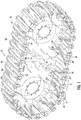
- Figure 1 shows a bogie comprising two wheels 12, 14.
- a caterpillar track 30, that is, chain track, comprises a plurality of successive grouser shoes, such as grouser shoes 32, 34, 36, in the direction of movement D of the caterpillar track 30.
- the grouser shoes 32, 34, 36 may be metal plates that increase the contact surface area of the caterpillar track 30 and consequently that of the entire work machine in relation to the surface of the terrain, that is, in relation to the ground.
- the caterpillar track 30 comprises a support structure 42, 44 supporting the grouser shoes such as grouser shoes 32, 34, 36, to which they are fastened or otherwise supported.
- the support structure 42, 44 of the caterpillar track 30 forms a closed circle so that the caterpillar track 30 forms a closed loop around the wheels 12, 14 of the work machine.
- the caterpillar track 30 has an outer surface 52, inner surface 54, first side edge 56, and second side edge 58.
- the grouser shoes 32, 34, 36 of the caterpillar track 30 extend from the first side edge 56 of the caterpillar track to the second side edge 58, that is, the narrow ends of the grouser shoes, such as ends 32a, 32b of the grouser shoe 32, are at the side edges 56, 58 of the caterpillar track.
- the longitudinal direction of the grouser shoes 32, 34, 36 is perpendicularly transverse in relation to the direction of travel, illustrated by the arrow D, of the caterpillar track.
- the caterpillar track On the side of the inner surface 54 of the caterpillar track 30, the caterpillar track comprises traction members 62, 64, 66 implemented with a chain, cable, rope, or another form-conformable structure. This improves traction.
- Chains or other similar traction members may reside entirely in the area between the grouser shoes, but in an embodiment the traction members are arranged at least partly overlapping, in other words, in alignment with the grouser shoes 32, 34, 36 of the caterpillar track 30. This way, the traction members 62, 64, 66 are between the wheels and caterpillar track 30 of the work machine, which increases friction i.e. achieves traction.
- the traction members, such as chains, are in the disclosed embodiment both overlapping, that is, in alignment with the grouser shoes and simultaneously in an area between two successive grouser shoes, as can be seen in the drawings.
- the traction members 62, 64, 66 such as chains, cables, or ropes, extend in the direction of the side edges 56, 58 of the caterpillar track, so in the transverse direction of the caterpillar track, in such a manner in the disclosed embodiment that the traction members 62, 64, 66 extend in the direction of the side edges 56, 58 of the caterpillar track 30 so that a traction member obliquely crosses a grouser shoe in a direction differing from the perpendicular direction between the side edges 56, 58 of the caterpillar track, the perpendicular direction being the longitudinal direction of the grouser shoe.
- the traction member such as 62, 64, 66 is in alignment over a larger area, so overlapping with a grouser shoe, causing improved traction between a wheel and a grouser shoe of the caterpillar track 30.
- the support structure 42, 44 of the caterpillar track 30 supporting the grouser shoes such as 32, 34, 36
- the support structure 42, 44 comprised by the caterpillar track 30 is a support chain structure comprising a chain structure 42, 44 on both side edges 56, 58 of the caterpillar track.
- Both chain structures 42, 44 comprise successive chain elements 42a, 42b, 44a, 44b such as side links.
- the traction members 62, 64, 66 such as chains, cables, or ropes, are between the chain structures 42, 44 on different side edges 56, 58 of the caterpillar track 30 and are fastened to the chain elements 42a, 42b of the chain structures 42, 44.
- the traction members are attached to the caterpillar track 30 on the inside surface 54 side of the caterpillar track in another manner, for example, so that (not shown) the traction members are fastened to the grouser shoes, to side guides of the caterpillar track (which, when the caterpillar track is rotating, run touching the top part of the side surface of the tyre, or past the top part of the side surface of the tyre), and it is also possible that there are specific fastening points made for the fastening of the traction members in, for example, the grouser shoes.
- traction members 62, 64, 66 such as chains, substantially over the entire area of the circumference/loop of the caterpillar track, as this results in even traction.
- a traction member may be a cable, rope, or another traction member conforming well to the shape of a tyre, which achieves good traction between a tyre of a wheel provided with a tyre, and the caterpillar track 30.
- a traction member has a form-conformable structure, that is, it is not stiff but is fixed by its fastening points at the ends, only, so the traction member is able to conform according to the surface between the tyre sides, which is towards the caterpillar track 30.
- Figure 2 shows similar structures as described in the above with reference to Figure 1 , but Figure 2 relates to a caterpillar track equipped with traction members for placement around a single wheel of a work machine.
- Figure 2 shows a caterpillar track 230 which has grouser shoes 332, 334, 336, side edges 356, 358, outer surface 352, and inner surface 354, and support structure 342, 344 of the caterpillar track.
- Figure 2 also has traction members 362, 364, 366 implemented with a rope or a similar structure. As concerns the other parts, reference is made to the details shown in Figure 1 .
- the caterpillar track 30 has a direction of movement and a transverse direction.
- the transverse direction of the caterpillar track is the same as the longitudinal direction of the grouser shoes such as 32, 34, 36.
- the transverse direction of the caterpillar track 30 is perpendicularly transverse in relation to the direction of movement of the caterpillar track 30.
- the direction of movement of the caterpillar track may be the opposite, too, and it is naturally so that the caterpillar track 30 forming a closed loop has opposite directions of movement, too.
- the caterpillar track 30 comprises traction members mutually directed in at least two different directions so that when examined from the same side edge of the caterpillar track (e.g. the first side edge 56), some of the traction members are directed obliquely towards the direction of movement of the caterpillar track and some other traction members are directed obliquely against the direction of movement of the caterpillar track 30.
- the same matter may also be expressed so that some of the traction members are directed to a different side in relation to the longitudinal direction of the caterpillar track 30 than some other traction members.
- the traction members obliquely directed towards the direction of movement are arranged alternately in relation to the traction members that are directed obliquely against the direction of movement.
- the same matter may also be expressed so that when examined from the same side edge of the caterpillar track 30, such as the side edge 56, the traction members directed on different sides in relation to the transverse direction of the caterpillar track 30 are arranged alternately.
- the caterpillar track 30 or a traction member comprised by it comprises a fastening arrangement 100, 110 for fastening or unfastening a traction member, such as the traction member 66 in Figure 1 .
- the fastening arrangement 100, 110 may be implemented in a number of ways, such as a bolt, shackle, or a slot in the caterpillar track.
- the fastening arrangement may be similar at both ends of the traction members such as a chain 66.
- the chain or similar traction members has some slack in it, that is, the chain is slightly longer than the direct distance between the chain fastening points of the caterpillar track 30. In such a case, traction is more easily achieved.
Landscapes
- Engineering & Computer Science (AREA)
- Mechanical Engineering (AREA)
- Chemical & Material Sciences (AREA)
- Combustion & Propulsion (AREA)
- Transportation (AREA)
- Life Sciences & Earth Sciences (AREA)
- Biodiversity & Conservation Biology (AREA)
- Ecology (AREA)
- Forests & Forestry (AREA)
- Environmental Sciences (AREA)
- Devices For Conveying Motion By Means Of Endless Flexible Members (AREA)
- Handcart (AREA)
Applications Claiming Priority (1)
| Application Number | Priority Date | Filing Date | Title |
|---|---|---|---|
| FI20205728A FI129138B (fi) | 2020-07-06 | 2020-07-06 | Työkoneen telamatto |
Publications (3)
| Publication Number | Publication Date |
|---|---|
| EP3936418A1 true EP3936418A1 (de) | 2022-01-12 |
| EP3936418C0 EP3936418C0 (de) | 2024-01-31 |
| EP3936418B1 EP3936418B1 (de) | 2024-01-31 |
Family
ID=76707996
Family Applications (1)
| Application Number | Title | Priority Date | Filing Date |
|---|---|---|---|
| EP21182269.7A Active EP3936418B1 (de) | 2020-07-06 | 2021-06-29 | Raupenkette einer arbeitsmaschine |
Country Status (4)
| Country | Link |
|---|---|
| EP (1) | EP3936418B1 (de) |
| CA (1) | CA3122979C (de) |
| FI (1) | FI129138B (de) |
| PL (1) | PL3936418T3 (de) |
Cited By (1)
| Publication number | Priority date | Publication date | Assignee | Title |
|---|---|---|---|---|
| CN120922259A (zh) * | 2025-10-11 | 2025-11-11 | 东华大学 | 履带单元、四驱履带行进底盘和水下作业机器人 |
Citations (5)
| Publication number | Priority date | Publication date | Assignee | Title |
|---|---|---|---|---|
| DE699465C (de) * | 1938-08-09 | 1940-11-29 | Rud Ketten Rieger & Dietz | Raupenkette |
| US4099794A (en) * | 1976-03-22 | 1978-07-11 | Hoffart Ronald J | Track pad |
| US20050241739A1 (en) * | 2004-04-29 | 2005-11-03 | Steve Kott | Removable tire chain assembly with paddles |
| US20060232130A1 (en) * | 2005-04-19 | 2006-10-19 | Christian Hansen | Traction apparatus for wheeled vehicles |
| US20180194180A1 (en) * | 2017-01-08 | 2018-07-12 | Samir Hanna Safar | Snow chain device for vehicle tire |
-
2020
- 2020-07-06 FI FI20205728A patent/FI129138B/fi active IP Right Grant
-
2021
- 2021-06-23 CA CA3122979A patent/CA3122979C/en active Active
- 2021-06-29 EP EP21182269.7A patent/EP3936418B1/de active Active
- 2021-06-29 PL PL21182269.7T patent/PL3936418T3/pl unknown
Patent Citations (5)
| Publication number | Priority date | Publication date | Assignee | Title |
|---|---|---|---|---|
| DE699465C (de) * | 1938-08-09 | 1940-11-29 | Rud Ketten Rieger & Dietz | Raupenkette |
| US4099794A (en) * | 1976-03-22 | 1978-07-11 | Hoffart Ronald J | Track pad |
| US20050241739A1 (en) * | 2004-04-29 | 2005-11-03 | Steve Kott | Removable tire chain assembly with paddles |
| US20060232130A1 (en) * | 2005-04-19 | 2006-10-19 | Christian Hansen | Traction apparatus for wheeled vehicles |
| US20180194180A1 (en) * | 2017-01-08 | 2018-07-12 | Samir Hanna Safar | Snow chain device for vehicle tire |
Cited By (1)
| Publication number | Priority date | Publication date | Assignee | Title |
|---|---|---|---|---|
| CN120922259A (zh) * | 2025-10-11 | 2025-11-11 | 东华大学 | 履带单元、四驱履带行进底盘和水下作业机器人 |
Also Published As
| Publication number | Publication date |
|---|---|
| FI129138B (fi) | 2021-08-13 |
| PL3936418T3 (pl) | 2024-06-24 |
| EP3936418C0 (de) | 2024-01-31 |
| CA3122979C (en) | 2023-08-22 |
| EP3936418B1 (de) | 2024-01-31 |
| CA3122979A1 (en) | 2022-01-06 |
| FI20205728A1 (fi) | 2021-08-13 |
Similar Documents
| Publication | Publication Date | Title |
|---|---|---|
| US6402268B1 (en) | Endless belt for use with heavy duty track vehicles | |
| US7300119B2 (en) | Rubber crawler | |
| US6030057A (en) | Tractor endless tread | |
| US6974196B2 (en) | Endless track for industrial or agricultural vehicles | |
| US20030047996A1 (en) | Endless track for high speed multi-terrain vehicles | |
| US4145092A (en) | Flexible track for vehicles | |
| US20110068620A1 (en) | Wear protectors for protecting guide and/or drive lugs of an endless track for traction of an off-road vehicle | |
| US8033619B2 (en) | Endless track | |
| US6322172B2 (en) | Endless belt for use with heavy duty track vehicles | |
| EP3936418B1 (de) | Raupenkette einer arbeitsmaschine | |
| US20160257358A1 (en) | Snow tread and cleat system for skidsteer implements | |
| US7530650B2 (en) | Crawler track shoe with multiple roller paths and multiple drive lugs | |
| US20100001580A1 (en) | Traction chain assembly for elastomeric tracks | |
| EP2271543B1 (de) | Querglieder für eine kette eines kettenfahrzeugs | |
| CN106232464A (zh) | 履带行走装置单元和林业机械 | |
| US20130147262A1 (en) | Cross-Links for a Track of a Tracked Vehicle | |
| US20030184157A1 (en) | Grouser assembly | |
| WO2011127554A1 (en) | Cross-links for a track of a tracked vehicle | |
| RU136764U1 (ru) | Гусеница для колеса задней тележки автомобиля | |
| US7252347B2 (en) | Belt over mid-rollers | |
| CN115723869B (zh) | 履带移动系统及移动装置 | |
| US20220379672A1 (en) | Chain system for a continuous track | |
| US3116956A (en) | Track assembly for endless track vehicle | |
| US5741052A (en) | Tractor endless tread | |
| US4856853A (en) | Endless belt-type drive mechanism |
Legal Events
| Date | Code | Title | Description |
|---|---|---|---|
| PUAI | Public reference made under article 153(3) epc to a published international application that has entered the european phase |
Free format text: ORIGINAL CODE: 0009012 |
|
| STAA | Information on the status of an ep patent application or granted ep patent |
Free format text: STATUS: THE APPLICATION HAS BEEN PUBLISHED |
|
| AK | Designated contracting states |
Kind code of ref document: A1 Designated state(s): AL AT BE BG CH CY CZ DE DK EE ES FI FR GB GR HR HU IE IS IT LI LT LU LV MC MK MT NL NO PL PT RO RS SE SI SK SM TR |
|
| B565 | Issuance of search results under rule 164(2) epc |
Effective date: 20211022 |
|
| STAA | Information on the status of an ep patent application or granted ep patent |
Free format text: STATUS: REQUEST FOR EXAMINATION WAS MADE |
|
| 17P | Request for examination filed |
Effective date: 20220118 |
|
| RBV | Designated contracting states (corrected) |
Designated state(s): AL AT BE BG CH CY CZ DE DK EE ES FI FR GB GR HR HU IE IS IT LI LT LU LV MC MK MT NL NO PL PT RO RS SE SI SK SM TR |
|
| STAA | Information on the status of an ep patent application or granted ep patent |
Free format text: STATUS: EXAMINATION IS IN PROGRESS |
|
| 17Q | First examination report despatched |
Effective date: 20220502 |
|
| GRAP | Despatch of communication of intention to grant a patent |
Free format text: ORIGINAL CODE: EPIDOSNIGR1 |
|
| STAA | Information on the status of an ep patent application or granted ep patent |
Free format text: STATUS: GRANT OF PATENT IS INTENDED |
|
| INTG | Intention to grant announced |
Effective date: 20230828 |
|
| GRAS | Grant fee paid |
Free format text: ORIGINAL CODE: EPIDOSNIGR3 |
|
| GRAA | (expected) grant |
Free format text: ORIGINAL CODE: 0009210 |
|
| STAA | Information on the status of an ep patent application or granted ep patent |
Free format text: STATUS: THE PATENT HAS BEEN GRANTED |
|
| AK | Designated contracting states |
Kind code of ref document: B1 Designated state(s): AL AT BE BG CH CY CZ DE DK EE ES FI FR GB GR HR HU IE IS IT LI LT LU LV MC MK MT NL NO PL PT RO RS SE SI SK SM TR |
|
| REG | Reference to a national code |
Ref country code: GB Ref legal event code: FG4D Ref country code: CH Ref legal event code: EP |
|
| REG | Reference to a national code |
Ref country code: DE Ref legal event code: R096 Ref document number: 602021008887 Country of ref document: DE |
|
| REG | Reference to a national code |
Ref country code: IE Ref legal event code: FG4D |
|
| U01 | Request for unitary effect filed |
Effective date: 20240221 |
|
| U07 | Unitary effect registered |
Designated state(s): AT BE BG DE DK EE FI FR IT LT LU LV MT NL PT SE SI Effective date: 20240229 |
|
| REG | Reference to a national code |
Ref country code: LT Ref legal event code: MG9D |
|
| PG25 | Lapsed in a contracting state [announced via postgrant information from national office to epo] |
Ref country code: IS Free format text: LAPSE BECAUSE OF FAILURE TO SUBMIT A TRANSLATION OF THE DESCRIPTION OR TO PAY THE FEE WITHIN THE PRESCRIBED TIME-LIMIT Effective date: 20240531 |
|
| PG25 | Lapsed in a contracting state [announced via postgrant information from national office to epo] |
Ref country code: GR Free format text: LAPSE BECAUSE OF FAILURE TO SUBMIT A TRANSLATION OF THE DESCRIPTION OR TO PAY THE FEE WITHIN THE PRESCRIBED TIME-LIMIT Effective date: 20240501 |
|
| PG25 | Lapsed in a contracting state [announced via postgrant information from national office to epo] |
Ref country code: RS Free format text: LAPSE BECAUSE OF FAILURE TO SUBMIT A TRANSLATION OF THE DESCRIPTION OR TO PAY THE FEE WITHIN THE PRESCRIBED TIME-LIMIT Effective date: 20240430 Ref country code: HR Free format text: LAPSE BECAUSE OF FAILURE TO SUBMIT A TRANSLATION OF THE DESCRIPTION OR TO PAY THE FEE WITHIN THE PRESCRIBED TIME-LIMIT Effective date: 20240131 |
|
| PG25 | Lapsed in a contracting state [announced via postgrant information from national office to epo] |
Ref country code: ES Free format text: LAPSE BECAUSE OF FAILURE TO SUBMIT A TRANSLATION OF THE DESCRIPTION OR TO PAY THE FEE WITHIN THE PRESCRIBED TIME-LIMIT Effective date: 20240131 |
|
| PG25 | Lapsed in a contracting state [announced via postgrant information from national office to epo] |
Ref country code: RS Free format text: LAPSE BECAUSE OF FAILURE TO SUBMIT A TRANSLATION OF THE DESCRIPTION OR TO PAY THE FEE WITHIN THE PRESCRIBED TIME-LIMIT Effective date: 20240430 Ref country code: NO Free format text: LAPSE BECAUSE OF FAILURE TO SUBMIT A TRANSLATION OF THE DESCRIPTION OR TO PAY THE FEE WITHIN THE PRESCRIBED TIME-LIMIT Effective date: 20240430 Ref country code: IS Free format text: LAPSE BECAUSE OF FAILURE TO SUBMIT A TRANSLATION OF THE DESCRIPTION OR TO PAY THE FEE WITHIN THE PRESCRIBED TIME-LIMIT Effective date: 20240531 Ref country code: HR Free format text: LAPSE BECAUSE OF FAILURE TO SUBMIT A TRANSLATION OF THE DESCRIPTION OR TO PAY THE FEE WITHIN THE PRESCRIBED TIME-LIMIT Effective date: 20240131 Ref country code: GR Free format text: LAPSE BECAUSE OF FAILURE TO SUBMIT A TRANSLATION OF THE DESCRIPTION OR TO PAY THE FEE WITHIN THE PRESCRIBED TIME-LIMIT Effective date: 20240501 Ref country code: ES Free format text: LAPSE BECAUSE OF FAILURE TO SUBMIT A TRANSLATION OF THE DESCRIPTION OR TO PAY THE FEE WITHIN THE PRESCRIBED TIME-LIMIT Effective date: 20240131 |
|
| U20 | Renewal fee for the european patent with unitary effect paid |
Year of fee payment: 4 Effective date: 20240627 |
|
| PG25 | Lapsed in a contracting state [announced via postgrant information from national office to epo] |
Ref country code: SM Free format text: LAPSE BECAUSE OF FAILURE TO SUBMIT A TRANSLATION OF THE DESCRIPTION OR TO PAY THE FEE WITHIN THE PRESCRIBED TIME-LIMIT Effective date: 20240131 |
|
| PG25 | Lapsed in a contracting state [announced via postgrant information from national office to epo] |
Ref country code: CZ Free format text: LAPSE BECAUSE OF FAILURE TO SUBMIT A TRANSLATION OF THE DESCRIPTION OR TO PAY THE FEE WITHIN THE PRESCRIBED TIME-LIMIT Effective date: 20240131 |
|
| PG25 | Lapsed in a contracting state [announced via postgrant information from national office to epo] |
Ref country code: SK Free format text: LAPSE BECAUSE OF FAILURE TO SUBMIT A TRANSLATION OF THE DESCRIPTION OR TO PAY THE FEE WITHIN THE PRESCRIBED TIME-LIMIT Effective date: 20240131 |
|
| PG25 | Lapsed in a contracting state [announced via postgrant information from national office to epo] |
Ref country code: SM Free format text: LAPSE BECAUSE OF FAILURE TO SUBMIT A TRANSLATION OF THE DESCRIPTION OR TO PAY THE FEE WITHIN THE PRESCRIBED TIME-LIMIT Effective date: 20240131 Ref country code: SK Free format text: LAPSE BECAUSE OF FAILURE TO SUBMIT A TRANSLATION OF THE DESCRIPTION OR TO PAY THE FEE WITHIN THE PRESCRIBED TIME-LIMIT Effective date: 20240131 Ref country code: RO Free format text: LAPSE BECAUSE OF FAILURE TO SUBMIT A TRANSLATION OF THE DESCRIPTION OR TO PAY THE FEE WITHIN THE PRESCRIBED TIME-LIMIT Effective date: 20240131 Ref country code: CZ Free format text: LAPSE BECAUSE OF FAILURE TO SUBMIT A TRANSLATION OF THE DESCRIPTION OR TO PAY THE FEE WITHIN THE PRESCRIBED TIME-LIMIT Effective date: 20240131 |
|
| REG | Reference to a national code |
Ref country code: DE Ref legal event code: R097 Ref document number: 602021008887 Country of ref document: DE |
|
| PLBE | No opposition filed within time limit |
Free format text: ORIGINAL CODE: 0009261 |
|
| STAA | Information on the status of an ep patent application or granted ep patent |
Free format text: STATUS: NO OPPOSITION FILED WITHIN TIME LIMIT |
|
| 26N | No opposition filed |
Effective date: 20241101 |
|
| PG25 | Lapsed in a contracting state [announced via postgrant information from national office to epo] |
Ref country code: MC Free format text: LAPSE BECAUSE OF FAILURE TO SUBMIT A TRANSLATION OF THE DESCRIPTION OR TO PAY THE FEE WITHIN THE PRESCRIBED TIME-LIMIT Effective date: 20240131 |
|
| REG | Reference to a national code |
Ref country code: CH Ref legal event code: PL |
|
| PG25 | Lapsed in a contracting state [announced via postgrant information from national office to epo] |
Ref country code: IE Free format text: LAPSE BECAUSE OF NON-PAYMENT OF DUE FEES Effective date: 20240629 |
|
| PG25 | Lapsed in a contracting state [announced via postgrant information from national office to epo] |
Ref country code: CH Free format text: LAPSE BECAUSE OF NON-PAYMENT OF DUE FEES Effective date: 20240630 |
|
| PGFP | Annual fee paid to national office [announced via postgrant information from national office to epo] |
Ref country code: PL Payment date: 20250618 Year of fee payment: 5 |
|
| PGFP | Annual fee paid to national office [announced via postgrant information from national office to epo] |
Ref country code: GB Payment date: 20250627 Year of fee payment: 5 |
|
| U20 | Renewal fee for the european patent with unitary effect paid |
Year of fee payment: 5 Effective date: 20250627 |
|
| PG25 | Lapsed in a contracting state [announced via postgrant information from national office to epo] |
Ref country code: CY Free format text: LAPSE BECAUSE OF FAILURE TO SUBMIT A TRANSLATION OF THE DESCRIPTION OR TO PAY THE FEE WITHIN THE PRESCRIBED TIME-LIMIT; INVALID AB INITIO Effective date: 20210629 |
|
| PG25 | Lapsed in a contracting state [announced via postgrant information from national office to epo] |
Ref country code: HU Free format text: LAPSE BECAUSE OF FAILURE TO SUBMIT A TRANSLATION OF THE DESCRIPTION OR TO PAY THE FEE WITHIN THE PRESCRIBED TIME-LIMIT; INVALID AB INITIO Effective date: 20210629 |