EP3936404B1 - Vehicle control system - Google Patents
Vehicle control system Download PDFInfo
- Publication number
- EP3936404B1 EP3936404B1 EP21179832.7A EP21179832A EP3936404B1 EP 3936404 B1 EP3936404 B1 EP 3936404B1 EP 21179832 A EP21179832 A EP 21179832A EP 3936404 B1 EP3936404 B1 EP 3936404B1
- Authority
- EP
- European Patent Office
- Prior art keywords
- take
- over
- steering
- controller circuit
- host vehicle
- Prior art date
- Legal status (The legal status is an assumption and is not a legal conclusion. Google has not performed a legal analysis and makes no representation as to the accuracy of the status listed.)
- Active
Links
Images


Classifications
-
- B—PERFORMING OPERATIONS; TRANSPORTING
- B60—VEHICLES IN GENERAL
- B60W—CONJOINT CONTROL OF VEHICLE SUB-UNITS OF DIFFERENT TYPE OR DIFFERENT FUNCTION; CONTROL SYSTEMS SPECIALLY ADAPTED FOR HYBRID VEHICLES; ROAD VEHICLE DRIVE CONTROL SYSTEMS FOR PURPOSES NOT RELATED TO THE CONTROL OF A PARTICULAR SUB-UNIT
- B60W60/00—Drive control systems specially adapted for autonomous road vehicles
- B60W60/005—Handover processes
- B60W60/0051—Handover processes from occupants to vehicle
-
- B—PERFORMING OPERATIONS; TRANSPORTING
- B60—VEHICLES IN GENERAL
- B60W—CONJOINT CONTROL OF VEHICLE SUB-UNITS OF DIFFERENT TYPE OR DIFFERENT FUNCTION; CONTROL SYSTEMS SPECIALLY ADAPTED FOR HYBRID VEHICLES; ROAD VEHICLE DRIVE CONTROL SYSTEMS FOR PURPOSES NOT RELATED TO THE CONTROL OF A PARTICULAR SUB-UNIT
- B60W60/00—Drive control systems specially adapted for autonomous road vehicles
- B60W60/005—Handover processes
- B60W60/0053—Handover processes from vehicle to occupant
-
- B—PERFORMING OPERATIONS; TRANSPORTING
- B60—VEHICLES IN GENERAL
- B60W—CONJOINT CONTROL OF VEHICLE SUB-UNITS OF DIFFERENT TYPE OR DIFFERENT FUNCTION; CONTROL SYSTEMS SPECIALLY ADAPTED FOR HYBRID VEHICLES; ROAD VEHICLE DRIVE CONTROL SYSTEMS FOR PURPOSES NOT RELATED TO THE CONTROL OF A PARTICULAR SUB-UNIT
- B60W30/00—Purposes of road vehicle drive control systems not related to the control of a particular sub-unit, e.g. of systems using conjoint control of vehicle sub-units
- B60W30/08—Active safety systems predicting or avoiding probable or impending collision or attempting to minimise its consequences
- B60W30/09—Taking automatic action to avoid collision, e.g. braking and steering
-
- B—PERFORMING OPERATIONS; TRANSPORTING
- B60—VEHICLES IN GENERAL
- B60W—CONJOINT CONTROL OF VEHICLE SUB-UNITS OF DIFFERENT TYPE OR DIFFERENT FUNCTION; CONTROL SYSTEMS SPECIALLY ADAPTED FOR HYBRID VEHICLES; ROAD VEHICLE DRIVE CONTROL SYSTEMS FOR PURPOSES NOT RELATED TO THE CONTROL OF A PARTICULAR SUB-UNIT
- B60W30/00—Purposes of road vehicle drive control systems not related to the control of a particular sub-unit, e.g. of systems using conjoint control of vehicle sub-units
- B60W30/08—Active safety systems predicting or avoiding probable or impending collision or attempting to minimise its consequences
- B60W30/095—Predicting travel path or likelihood of collision
-
- B—PERFORMING OPERATIONS; TRANSPORTING
- B60—VEHICLES IN GENERAL
- B60W—CONJOINT CONTROL OF VEHICLE SUB-UNITS OF DIFFERENT TYPE OR DIFFERENT FUNCTION; CONTROL SYSTEMS SPECIALLY ADAPTED FOR HYBRID VEHICLES; ROAD VEHICLE DRIVE CONTROL SYSTEMS FOR PURPOSES NOT RELATED TO THE CONTROL OF A PARTICULAR SUB-UNIT
- B60W30/00—Purposes of road vehicle drive control systems not related to the control of a particular sub-unit, e.g. of systems using conjoint control of vehicle sub-units
- B60W30/10—Path keeping
- B60W30/12—Lane keeping
-
- B—PERFORMING OPERATIONS; TRANSPORTING
- B60—VEHICLES IN GENERAL
- B60W—CONJOINT CONTROL OF VEHICLE SUB-UNITS OF DIFFERENT TYPE OR DIFFERENT FUNCTION; CONTROL SYSTEMS SPECIALLY ADAPTED FOR HYBRID VEHICLES; ROAD VEHICLE DRIVE CONTROL SYSTEMS FOR PURPOSES NOT RELATED TO THE CONTROL OF A PARTICULAR SUB-UNIT
- B60W50/00—Details of control systems for road vehicle drive control not related to the control of a particular sub-unit, e.g. process diagnostic or vehicle driver interfaces
- B60W50/0098—Details of control systems ensuring comfort, safety or stability not otherwise provided for
-
- B—PERFORMING OPERATIONS; TRANSPORTING
- B60—VEHICLES IN GENERAL
- B60W—CONJOINT CONTROL OF VEHICLE SUB-UNITS OF DIFFERENT TYPE OR DIFFERENT FUNCTION; CONTROL SYSTEMS SPECIALLY ADAPTED FOR HYBRID VEHICLES; ROAD VEHICLE DRIVE CONTROL SYSTEMS FOR PURPOSES NOT RELATED TO THE CONTROL OF A PARTICULAR SUB-UNIT
- B60W60/00—Drive control systems specially adapted for autonomous road vehicles
- B60W60/005—Handover processes
- B60W60/0053—Handover processes from vehicle to occupant
- B60W60/0055—Handover processes from vehicle to occupant only part of driving tasks shifted to occupants
-
- B—PERFORMING OPERATIONS; TRANSPORTING
- B62—LAND VEHICLES FOR TRAVELLING OTHERWISE THAN ON RAILS
- B62D—MOTOR VEHICLES; TRAILERS
- B62D1/00—Steering controls, i.e. means for initiating a change of direction of the vehicle
- B62D1/24—Steering controls, i.e. means for initiating a change of direction of the vehicle not vehicle-mounted
- B62D1/28—Steering controls, i.e. means for initiating a change of direction of the vehicle not vehicle-mounted non-mechanical, e.g. following a line or other known markers
- B62D1/286—Systems for interrupting non-mechanical steering due to driver intervention
-
- B—PERFORMING OPERATIONS; TRANSPORTING
- B62—LAND VEHICLES FOR TRAVELLING OTHERWISE THAN ON RAILS
- B62D—MOTOR VEHICLES; TRAILERS
- B62D15/00—Steering not otherwise provided for
- B62D15/02—Steering position indicators ; Steering position determination; Steering aids
- B62D15/025—Active steering aids, e.g. helping the driver by actively influencing the steering system after environment evaluation
- B62D15/0255—Automatic changing of lane, e.g. for passing another vehicle
-
- B—PERFORMING OPERATIONS; TRANSPORTING
- B62—LAND VEHICLES FOR TRAVELLING OTHERWISE THAN ON RAILS
- B62D—MOTOR VEHICLES; TRAILERS
- B62D15/00—Steering not otherwise provided for
- B62D15/02—Steering position indicators ; Steering position determination; Steering aids
- B62D15/025—Active steering aids, e.g. helping the driver by actively influencing the steering system after environment evaluation
- B62D15/0265—Automatic obstacle avoidance by steering
-
- B—PERFORMING OPERATIONS; TRANSPORTING
- B60—VEHICLES IN GENERAL
- B60W—CONJOINT CONTROL OF VEHICLE SUB-UNITS OF DIFFERENT TYPE OR DIFFERENT FUNCTION; CONTROL SYSTEMS SPECIALLY ADAPTED FOR HYBRID VEHICLES; ROAD VEHICLE DRIVE CONTROL SYSTEMS FOR PURPOSES NOT RELATED TO THE CONTROL OF A PARTICULAR SUB-UNIT
- B60W50/00—Details of control systems for road vehicle drive control not related to the control of a particular sub-unit, e.g. process diagnostic or vehicle driver interfaces
- B60W2050/0001—Details of the control system
- B60W2050/0043—Signal treatments, identification of variables or parameters, parameter estimation or state estimation
-
- B—PERFORMING OPERATIONS; TRANSPORTING
- B60—VEHICLES IN GENERAL
- B60W—CONJOINT CONTROL OF VEHICLE SUB-UNITS OF DIFFERENT TYPE OR DIFFERENT FUNCTION; CONTROL SYSTEMS SPECIALLY ADAPTED FOR HYBRID VEHICLES; ROAD VEHICLE DRIVE CONTROL SYSTEMS FOR PURPOSES NOT RELATED TO THE CONTROL OF A PARTICULAR SUB-UNIT
- B60W2420/00—Indexing codes relating to the type of sensors based on the principle of their operation
- B60W2420/40—Photo, light or radio wave sensitive means, e.g. infrared sensors
- B60W2420/403—Image sensing, e.g. optical camera
-
- B—PERFORMING OPERATIONS; TRANSPORTING
- B60—VEHICLES IN GENERAL
- B60W—CONJOINT CONTROL OF VEHICLE SUB-UNITS OF DIFFERENT TYPE OR DIFFERENT FUNCTION; CONTROL SYSTEMS SPECIALLY ADAPTED FOR HYBRID VEHICLES; ROAD VEHICLE DRIVE CONTROL SYSTEMS FOR PURPOSES NOT RELATED TO THE CONTROL OF A PARTICULAR SUB-UNIT
- B60W2420/00—Indexing codes relating to the type of sensors based on the principle of their operation
- B60W2420/40—Photo, light or radio wave sensitive means, e.g. infrared sensors
- B60W2420/408—Radar; Laser, e.g. lidar
-
- B—PERFORMING OPERATIONS; TRANSPORTING
- B60—VEHICLES IN GENERAL
- B60W—CONJOINT CONTROL OF VEHICLE SUB-UNITS OF DIFFERENT TYPE OR DIFFERENT FUNCTION; CONTROL SYSTEMS SPECIALLY ADAPTED FOR HYBRID VEHICLES; ROAD VEHICLE DRIVE CONTROL SYSTEMS FOR PURPOSES NOT RELATED TO THE CONTROL OF A PARTICULAR SUB-UNIT
- B60W2510/00—Input parameters relating to a particular sub-units
- B60W2510/20—Steering systems
- B60W2510/202—Steering torque
-
- B—PERFORMING OPERATIONS; TRANSPORTING
- B60—VEHICLES IN GENERAL
- B60W—CONJOINT CONTROL OF VEHICLE SUB-UNITS OF DIFFERENT TYPE OR DIFFERENT FUNCTION; CONTROL SYSTEMS SPECIALLY ADAPTED FOR HYBRID VEHICLES; ROAD VEHICLE DRIVE CONTROL SYSTEMS FOR PURPOSES NOT RELATED TO THE CONTROL OF A PARTICULAR SUB-UNIT
- B60W2510/00—Input parameters relating to a particular sub-units
- B60W2510/20—Steering systems
- B60W2510/205—Steering speed
-
- B—PERFORMING OPERATIONS; TRANSPORTING
- B60—VEHICLES IN GENERAL
- B60W—CONJOINT CONTROL OF VEHICLE SUB-UNITS OF DIFFERENT TYPE OR DIFFERENT FUNCTION; CONTROL SYSTEMS SPECIALLY ADAPTED FOR HYBRID VEHICLES; ROAD VEHICLE DRIVE CONTROL SYSTEMS FOR PURPOSES NOT RELATED TO THE CONTROL OF A PARTICULAR SUB-UNIT
- B60W2520/00—Input parameters relating to overall vehicle dynamics
- B60W2520/12—Lateral speed
- B60W2520/125—Lateral acceleration
-
- B—PERFORMING OPERATIONS; TRANSPORTING
- B60—VEHICLES IN GENERAL
- B60W—CONJOINT CONTROL OF VEHICLE SUB-UNITS OF DIFFERENT TYPE OR DIFFERENT FUNCTION; CONTROL SYSTEMS SPECIALLY ADAPTED FOR HYBRID VEHICLES; ROAD VEHICLE DRIVE CONTROL SYSTEMS FOR PURPOSES NOT RELATED TO THE CONTROL OF A PARTICULAR SUB-UNIT
- B60W2540/00—Input parameters relating to occupants
- B60W2540/18—Steering angle
-
- B—PERFORMING OPERATIONS; TRANSPORTING
- B60—VEHICLES IN GENERAL
- B60W—CONJOINT CONTROL OF VEHICLE SUB-UNITS OF DIFFERENT TYPE OR DIFFERENT FUNCTION; CONTROL SYSTEMS SPECIALLY ADAPTED FOR HYBRID VEHICLES; ROAD VEHICLE DRIVE CONTROL SYSTEMS FOR PURPOSES NOT RELATED TO THE CONTROL OF A PARTICULAR SUB-UNIT
- B60W2552/00—Input parameters relating to infrastructure
- B60W2552/30—Road curve radius
-
- B—PERFORMING OPERATIONS; TRANSPORTING
- B60—VEHICLES IN GENERAL
- B60W—CONJOINT CONTROL OF VEHICLE SUB-UNITS OF DIFFERENT TYPE OR DIFFERENT FUNCTION; CONTROL SYSTEMS SPECIALLY ADAPTED FOR HYBRID VEHICLES; ROAD VEHICLE DRIVE CONTROL SYSTEMS FOR PURPOSES NOT RELATED TO THE CONTROL OF A PARTICULAR SUB-UNIT
- B60W2552/00—Input parameters relating to infrastructure
- B60W2552/50—Barriers
-
- B—PERFORMING OPERATIONS; TRANSPORTING
- B60—VEHICLES IN GENERAL
- B60W—CONJOINT CONTROL OF VEHICLE SUB-UNITS OF DIFFERENT TYPE OR DIFFERENT FUNCTION; CONTROL SYSTEMS SPECIALLY ADAPTED FOR HYBRID VEHICLES; ROAD VEHICLE DRIVE CONTROL SYSTEMS FOR PURPOSES NOT RELATED TO THE CONTROL OF A PARTICULAR SUB-UNIT
- B60W2710/00—Output or target parameters relating to a particular sub-units
- B60W2710/20—Steering systems
- B60W2710/207—Steering angle of wheels
Definitions
- This invention generally relates to a control system for a vehicle.
- a driver take-over from automated driving to manual driving may create instability in the steering of a vehicle.
- US 2020 / 0 001 882 A1 discloses an apparatus and a method for monitoring the activity of a driver of a vehicle
- This invention relates to a vehicle control system that classifies the driver's take-over, based on inputs to the steering wheel, and determines a level of driver assistance during the transition from automated to manual driving, based on the context of the environment around the vehicle.
- a vehicle control system according to claim 1 is provided.
- the controller circuit determines a level of automated driver assistance based on the steering sensor and the environment.
- the controller circuit determines that the operator requests the take-over when the steering torque is greater than a first threshold.
- the one or more perception sensors include one of a camera, a RADAR, a LiDAR, and an inertial measurement unit.
- the steering sensor is further configured to detect a steering angle and a steering angle rate.
- the controller circuit classifies a first take-over when, a maximum steering angle is less than a second threshold, a maximum steering angle rate is greater than a third threshold and less than a fourth threshold.
- the controller circuit classifies a second take-over when, a maximum steering angle is less than a second threshold, and a maximum steering angle rate is less than a third threshold.
- the controller circuit further determines the level of automated driver assistance based on a radius of curvature of a roadway.
- the controller circuit further determines the level of automated driver assistance based on a lateral acceleration of the host vehicle.
- a method of operating the vehicle control system according to claim 10 is provided.
- the controller circuit determines a level of automated driver assistance based on the steering sensor and the environment.
- the controller circuit determines that the operator requests the take-over when the steering torque is greater than a first threshold.
- the one or more perception sensors include one of a camera, a RADAR, a LiDAR, and an inertial measurement unit.
- the steering sensor is further configured to detect a steering angle and a steering angle rate.
- This present invention relates a vehicle control system configured to classify a type of operator take-over, after which the system provides an appropriate level of driver assistance during the transition from automated to manual driving.
- the vehicle control system described with reference to the present invention is in contrast to other systems that merely hand-over control to the driver with no transition period for driver assistance.
- the vehicle control system accomplishes this by inferring an urgency of the take-over based on the driver's input to the steering wheel (i.e., steering torque, steering angle, and steering angle rate), then verifying the urgency of the take-over based on sensors (e.g., RADAR, LiDAR, cameras, relative movement) that detect the surrounding environment.
- sensors e.g., RADAR, LiDAR, cameras, relative movement
- Fig. 1 illustrates an example of a vehicle control system 10, hereafter referred to as the system 10, installed on a host vehicle 12.
- the host vehicle 12 may be characterized as an automated vehicle.
- the term automated vehicle may apply to instances when the host vehicle 12 is being operated in an automated driving mode, i.e. a fully autonomous driving mode, where the operator of the host vehicle 12 may do little more than designate a destination to operate the host vehicle 12.
- the host vehicle 12 may also be operated in a manual driving mode where the degree or level of automation may be little more than providing an audible or visual warning to the human operator who is generally in control of the steering, accelerator, and brakes of the host vehicle 12.
- the system may merely assist the operator as needed to change lanes and/or avoid interference with and/or a collision with, an object such as another vehicle, a pedestrian, or a road sign.
- the manual driving mode may include driver assistance features, such as lane keeping, cruise control, collision avoidance, and parking assistance.
- the system 10 includes a controller circuit 14 in communication with a steering sensor 16 and one or more perception sensors 18.
- the controller circuit 14 may be integrated with and share a memory and/or other components with other vehicle control devices (not shown), or may be a stand-alone device.
- the controller circuit 14 may include a processor (not shown) such as a microprocessor or other control circuitry such as analog and/or digital control circuitry.
- the control circuitry may include one or more application-specific integrated circuits (ASICs) or field programmable gate arrays (FPGAs) that are programmed to perform the techniques, or may include one or more general purpose hardware processors programmed to perform the techniques pursuant to program instructions in firmware, memory, other storage, or a combination.
- ASICs application-specific integrated circuits
- FPGAs field programmable gate arrays
- the controller circuit 14 may also combine custom hard-wired logic, ASICs, or FPGAs with custom programming to accomplish the techniques.
- the controller circuit 14 may include a memory or storage media (not shown), including non-volatile memory, such as electrically erasable programmable read-only memory (EEPROM) for storing one or more routines, thresholds, and captured data.
- EEPROM electrically erasable programmable read-only memory
- the controller circuit 14 may include other examples of non-volatile memory, such as flash memory, read-only memory (ROM), programmable read-only memory (PROM), and erasable programmable read-only memory (EPROM).
- the controller circuit 14 may include volatile memory, such as dynamic random-access memory (DRAM), static random-access memory (SRAM).
- DRAM dynamic random-access memory
- SRAM static random-access memory
- the one or more routines may be executed by the processor to perform steps for controlling the host vehicle 12, based on signals received by the controller circuit 14 from the steering sensor 16 and the one or more perception sensors 18 as described herein.
- Fig. 2 illustrates an example of the steering sensor 16 isolated from the system 10.
- the steering sensor 16 is configured to detect a steering torque 20, a steering angle 22, and a steering angle rate 24 of the steering wheel of the host vehicle 12.
- the steering sensor 16 is mounted to a steering column of the host vehicle 12 and communicates with the controller circuit 14 via a controller area network bus (CAN bus - not shown).
- the steering sensor 16 is comprised of multiple sensors mounted in different positions on the steering column that provide individual output signals of the steering torque 20, the steering angle 22, and the steering angle rate 24 to the controller circuit 14.
- the steering sensor 16 is a single sensor that provides multiple output signals of the steering torque 20, the steering angle 22, and the steering angle rate 24 to the controller circuit 14.
- Fig. 3 illustrates an example of the one or more perception sensors 18 isolated from the system 10.
- the one or more perception sensors 18 may include ranging sensors, such as RADAR, light detection and ranging (LiDAR), and ultrasonic sensors (not shown).
- the one or more perception sensors 18 may also include vision sensors such as cameras, including video cameras, time of flight (TOF) camera, etc.
- the cameras may be mounted on the front, rear, and sides of the host vehicle 12, or mounted in the interior of the host vehicle 12 at a location suitable for the camera to view the area around the host-vehicle 12 through the windows of the host vehicle 12.
- the cameras are preferably video type cameras that can capture images of the roadway and surrounding area at a sufficient frame-rate, of at least ten frames per second, for example.
- the one or more perception sensors 18 may also include an inertial measurement unit (IMU) that detects relative movement of the host vehicle 12.
- the relative movement measured by the IMU may include the host vehicle's 12 current yaw rate, longitudinal acceleration, lateral acceleration, pitch rate, and roll rate.
- the one or more perception sensors 18 may also include a global navigation satellite system (GNSS) receiver.
- the GNSS receiver may receive signals from orbiting satellites from any of the known satellite systems, including Global Positioning System (GPS), Globalnaya Navigazionnaya Sputnikovayassela (GLONASS), BeiDou Navigation Satellite System (BDS), and Galileo global navigation satellite system.
- GPS Global Positioning System
- GLONASS Globalnaya Navigazionnaya Sputnikovaya
- BDS BeiDou Navigation Satellite System
- Galileo global navigation satellite system Galileo global navigation satellite system.
- the one or more perception sensors 18 may be distributed around the host vehicle 12 and provide a 360 degree view of the environment in which the host vehicle 12 is operating, and are configured to detect the environment proximate the host vehicle 12.
- the ranging sensors are used for detecting ranges and closing rates to objects and/or obstacles proximate the host vehicle 12.
- the cameras are used to detect and classify the objects and/or obstacles, such as lane markings, roadway edges, pedestrians, other vehicles, etc.
- data from the one or more perception sensors 18 are fused to associate detections from the ranging sensors with the classifications from the cameras.
- the controller circuit 14 is configured to determine when an operator of the host vehicle 12 requests a take-over from fully automated control of the host vehicle 12 based on the steering sensor 16, and further classifies the take-over request based on the output from the steering sensor 16.
- the steering sensor 16 detects when the operator places one or more hands on the steering wheel by measuring a change in the steering torque 20.
- Fig. 4 illustrates a graph of the steering torque 20 as a function of time. Data is plotted for three classifications of operator take-over request (i.e., Type I, II, and III), that will be described in more detail below. While three classifications of operator take-over request are described in relation with the present invention, it will be appreciated that any number of take-over requests may be indicated using the system 10 described herein.
- the number of classifications may be increased or decreased based on the granularity desired by the user, and/or based on the resolution of the steering sensor 16.
- the steering torque 20 is essentially zero and indicative of the vehicle being steered in the autonomous mode where the operator's hands are not touching the steering wheel.
- the three plots indicate a change in the steering torque 20 that is substantially non-zero.
- the controller circuit 14 determines that the operator requests the take-over when the steering torque 20 is greater than a first threshold, illustrated by a dashed line positioned at -2Nm of steering torque 20.
- the first threshold may be user defined, and in this example is indicated as -2Nm, which provides a sufficient trade-off between true and false operator take-over requests. It will be appreciated that the threshold may also be set to include +2Nm, as the steering torque 20 is detected for both clockwise and counter-clockwise rotations of the steering wheel. In another example, an absolute value of the steering torque 20 is used for the first threshold. In another example, the controller circuit 14 determines that the operator requests the take-over when the steering torque 20 is greater than the first threshold for a defined period of time. In this example, the controller circuit 14 may reduce false or erroneous requests for operator take-over, such as when an operator inadvertently moves the steering wheel. The defined period of time may be user defined and, in an example, is in a range from between zero to one second.
- Figs. 5 and 6 are graphs of the steering angle 22 and the steering angle rate 24 as a function of time for the three classifications of operator take-over request, and correspond to the graph of steering torque 20 illustrated in Fig. 4 .
- the three classifications of operator take-over request indicate detectably different plots of steering angle 22 and steering angle rate 24. These detectable differences are used by the controller circuit 14 to determine whether the classification is a Type I, a Type II, or a Type III take-over request by comparing the steering angle 22 and steering angle rate 24 to respective thresholds.
- the classification is a Type I, a Type II, or a Type III take-over request.
- the controller circuit 14 classifies a first take-over (i.e., Type I) that is indicated by relatively small steering angles 22 and relatively rapid steering angle rates 24, such as when the operator turns or shakes the steering wheel in a random manner.
- the Type I take-over may be indicative of the operator resuming control of the host vehicle 12 in non-emergency situations, and/or when no obstacle is in the path of the host vehicle 12.
- the controller circuit 14 classifies the Type I take-over when a maximum steering angle 22 is less than a second threshold (e.g., 25 degrees), and when a maximum steering angle rate 24 is greater than a third threshold (e.g., 1.5 degrees/second) but less than a fourth threshold (e.g., 3 degrees/second).
- the controller circuit 14 classifies a second take-over (i.e., Type II) that is indicated by relatively small steering angles 22 and relatively slow steering angle rates 24, such as when the operator exerts a relatively mild or soft persistent turn or rotation on the steering wheel.
- the Type II take-over may be indicative of the operator resuming control of the host vehicle 12 when in-lane biasing of the host vehicle 12 may be required to avoid an obstacle is in the path of the host vehicle 12, such as a pothole or debris.
- the controller circuit 14 classifies the Type II take-over when the maximum steering angle 22 is less than the second threshold (e.g., 25 degrees), and the maximum steering angle rate 24 is less than a third threshold (e.g., 1.5 degrees/second).
- the controller circuit 14 classifies a third take-over (i.e., Type Ill) that is indicated by relatively large steering angles 22 and relatively rapid steering angle rates 24, such as when the operator exerts a relatively hard persistent turn or rotation on the steering wheel.
- the Type III take-over may be indicative of the operator resuming control of the host vehicle 12 in emergency situations when a lane change may be required to avoid an obstacle is in the path of the host vehicle 12.
- the controller circuit 14 classifies the Type III take-over when the maximum steering angle 22 is greater than a fifth threshold (e.g., 40 degrees), and the maximum steering angle rate 24 is greater than the fourth threshold (e.g., 3 degrees/second).
- a fifth threshold e.g. 40 degrees
- the maximum steering angle rate 24 e.g., 3 degrees/second.
- the first, second, third, fourth, and fifth thresholds in the above examples may be determined by the user and may be calibrated based on the vehicle dynamics of the particular application.
- the controller circuit 14 is further configured to determine a level of automated driver assistance based on the steering sensor 16, and based on the environment detected by the one or more perception sensors 18.
- the controller circuit 14 is configured to enable the automated driver assistance features during the transition from fully automated driving to manual driving to ensure a safe transition.
- the level of automated driver assistance includes: steering assistance applied for lane keeping and/or collision avoidance (e.g., evasive steering and/or emergency braking); limitations on a maximum steering angle 22 applied by the driver to inhibit vehicle instability; automated braking and speed control; and warnings for lane departure and/or collision.
- the automated driver assistance may be enabled for a time period or time threshold that may be predetermined (e.g., 5 seconds), or a dynamic time threshold that may be varied based on the environment and/or the host vehicle 12 operating conditions (e.g., host vehicle speed, road conditions, road geometry, detected obstructions, etc., or any combinations thereof).
- a time period or time threshold may be predetermined (e.g., 5 seconds), or a dynamic time threshold that may be varied based on the environment and/or the host vehicle 12 operating conditions (e.g., host vehicle speed, road conditions, road geometry, detected obstructions, etc., or any combinations thereof).
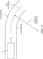
- Fig. 8 illustrates another example of a logic flow performed by the controller circuit 14 where the one or more perception sensors 18 are used to detect an obstacle and road conditions.
- the controller circuit 14 when the controller circuit 14 classifies a first take-over (i.e., Type I) and no obstacle is detected by the one or more perception sensors 18, the controller circuit 14 further determines the level of automated driver assistance based on a radius of curvature (ROC) of the roadway exceeding a curvature threshold, and/or based on a lateral acceleration of the host vehicle 12 exceeding an acceleration threshold (e.g., greater than 5 m/s2).
- Fig. 9 illustrates the host vehicle 12 entering a curved section of the roadway.
- the controller circuit 14 is configured to determine the ROC of the roadway based on images of the roadway captured by the camera using known techniques for image analysis.
- the camera may detect lane markings and/or road edges that may be processed by the controller circuit 14 to determine a lane polynomial that corresponds to a center of the travel lane, from which the ROC may be determined.
- vision processing technologies such as the EYE Q ® platform from Moblieye Vision Technologies, Ltd. of Jerusalem, Israel, or other suitable devices may be used to determine the lane polynomial, and may be integrated with the controller circuit 14, or may be a separate package in communication with the controller circuit 14.
- the controller circuit 14 may use any of the known methods for determining the lane polynomial, including, but not limited to, a least squares method and an interpolation method.
- the controller circuit 14 is configured to determine the ROC based on a digital map that may be accessed by the host vehicle 12 from the memory of the controller circuit 14, or via a cloud-based service. In this example, the controller circuit 14 may determine a position of the host vehicle 12 relative to the curved section of the roadway via the GNSS receiver. In another example, the controller circuit 14 determines the lateral acceleration of the host vehicle 12 based on signals received from the IMU as the host vehicle 12 enters the curved section of the roadway where centrifugal forces act on the host vehicle 12.
- the controller circuit 14 when the controller circuit 14 determines that the host vehicle 12 is traveling on the roadway with a ROC greater than the curvature threshold, or when the lateral acceleration of the host vehicle 12 measured by the IMU is greater than the acceleration threshold, the controller circuit 14 limits the maximum steering angle 22 that may be applied by the driver to maintain lateral stability of the host vehicle 12. That is, the controller circuit 14 limits the amount of steering angle 22 the driver may apply during the take-over transition so that the driver does not lose control of the host vehicle 12 by making excessive (and possibly unnecessary) steering maneuvers.
- the maximum steering angle threshold may vary based on a dynamic response of the host vehicle 12, and may be calculated based on a dynamic model of the host vehicle 12 using the current vehicle state parameters that include: the current steering angle 22, the current lateral acceleration, and the current vehicle yaw rate. It will be appreciated that other vehicle state parameters may be included in the calculation of the maximum steering angle threshold.
- the controller circuit 14 enables the necessary driver assistance (e.g., lane keeping assistance) for the time threshold, then disables the automated driver assistance after which the driver assumes complete control of the host vehicle 12.
- the controller circuit 14 determines whether an obstacle is detected by the one or more perception sensors 18. When the obstacle is detected, the controller circuit 14 enables the necessary driver assistance to avoid a collision with the obstacle and enables a collision warning from an alert device alerting the driver to the potential collision.
- the alert device may be one or more of an audible device, a visual device, and a haptic device that alerts the driver to the potential collision.
- the controller circuit 14 determines whether the ROC of the roadway or the lateral acceleration is greater than their respective thresholds.
- the controller circuit 14 limits the amount of steering angle 22 the driver may apply during the transition so that the driver does not lose control of the host vehicle 12. In this example, the controller circuit 14 then enables the necessary driver assistance (e.g., lane keeping assistance) for a period of time equal to the time threshold, after which the driver assumes complete control of the host vehicle 12.
- the necessary driver assistance e.g., lane keeping assistance
- the controller circuit 14 determines whether an obstacle is detected by the one or more perception sensors 18. When the obstacle is detected, the controller circuit 14 enables the evasive driver assistance to avoid the imminent threat of the collision with the obstacle. While not shown, the controller circuit 14 may also enable the collision warning from the alert device alerting the driver to the impending collision with the obstacle. In this example, when no obstacle is detected, the controller circuit 14 determines whether the ROC of the roadway or the lateral acceleration is greater than their respective thresholds.
- the controller circuit 14 limits the amount of steering angle 22 the driver may apply during the transition so that the driver does not lose control of the host vehicle 12. In this example, the controller circuit 14 then enables the necessary driver assistance (e.g., lane keeping assistance) for a period of time equal to the time threshold, after which the driver assumes complete control of the host vehicle 12.
- the necessary driver assistance e.g., lane keeping assistance
- Fig. 10 is a flow chart of a method 100 of operating the vehicle control system 10.
- Step 102 DETECT STEERING TORQUE, includes detecting the steering torque 20 of the steering wheel of the host vehicle 12 with the steering sensor 16 as described above.
- the steering sensor 16 is configured to detect the steering torque 20, the steering angle 22, and the steering angle rate 24.
- the steering sensor 16 communicates with the controller circuit 14 via the host vehicle's 12 CAN bus.
- the steering sensor 16 may be a single device or multiple devices as described above.
- Step 104 DETECT ENVIRONMENT, includes detecting the environment proximate the host vehicle 12 with one or more perception sensors 18.
- the one or more perception sensors 18 include ranging sensors, vision sensors, GNSS, and the IMU as described above.
- the one or more perception sensors 18 may be distributed around the host vehicle 12 and provide a 360 degree view of the environment in which the host vehicle 12 is operating.
- Step 106 DETERMINE TAKE-OVER REQUEST, includes determining, with the controller circuit 14 in communication with the steering sensor 16 and the one or more perception sensors 18, when the operator of the host vehicle 12 requests the take-over based on the steering sensor 16.
- the steering sensor 16 detects when the operator places one or more hands on the steering wheel by measuring the change in the steering torque 20 and comparing the steering torque 20 to a first threshold.
- the controller circuit 14 determines that the operator requests the take-over when the steering torque 20 is greater than the first threshold, as described above.
- Step 108 includes classifying, with the controller circuit 14, the take-over request based on the steering sensor 16.
- the controller circuit 14 classifies the taker-over as the first take-over request (Type I), the second take-over request (Type II), or the third take-over request (Type III), by comparing the steering angle 22 and steering angle rate 24 to their respective thresholds, as described above.
- the controller circuit 14 further determines the level of automated driver assistance enabled during the transition from fully automated driving to manual driving to promote a safe transition.
- the level of automated driver assistance is based on the type of take-over request and whether obstacles are detected with the one or more perception sensors 18, as described above.
- the level of automated driver assistance includes steering assistance applied for lane keeping and/or collision avoidance, limitations on the maximum steering angle 22 applied by the driver to inhibit vehicle instability, automated braking and speed control, and warnings for lane departure and/or collision.
- the controller circuit 14 further determines the level of automated driver assistance based on the ROC of the roadway or based on the lateral acceleration of the host vehicle 12, as described above.
- the controller circuit 14 limits the amount of steering angle 22 the driver may apply during the transition so that the driver does not lose control of the host vehicle 12.
- the controller circuit 14 then enables the necessary driver assistance for a period of time equal to the time threshold, after which the driver assumes complete control of the host vehicle 12.
- a vehicle control system 10 and a method 100 of operating the vehicle control system 10 are provided.
- the vehicle control system 10 may provide advantages over other vehicle control systems because the system 10 enables a level of automated driver assistance during the transition from fully automated driving to manual driving.
Landscapes
- Engineering & Computer Science (AREA)
- Transportation (AREA)
- Mechanical Engineering (AREA)
- Automation & Control Theory (AREA)
- Human Computer Interaction (AREA)
- Chemical & Material Sciences (AREA)
- Combustion & Propulsion (AREA)
- Traffic Control Systems (AREA)
- Steering Control In Accordance With Driving Conditions (AREA)
Description
- This invention generally relates to a control system for a vehicle. A driver take-over from automated driving to manual driving may create instability in the steering of a vehicle.
-
US 2020 / 0 001 882 A1 discloses an apparatus and a method for monitoring the activity of a driver of a vehicle - When a driver assumes control of an autonomously driven vehicle and places their hands on a steering wheel, the driver's steering reaction during the take-over transition may be excessive for the environment in which the vehicle is operating. Such steering reactions may cause the vehicle to deviate from, or within, a travel lane unnecessarily, until the driver is in full control of the vehicle. This invention relates to a vehicle control system that classifies the driver's take-over, based on inputs to the steering wheel, and determines a level of driver assistance during the transition from automated to manual driving, based on the context of the environment around the vehicle.
- According to a first aspect of the invention, a vehicle control system according to
claim 1 is provided. - In an embodiment, the controller circuit determines a level of automated driver assistance based on the steering sensor and the environment.
- In an embodiment, the controller circuit determines that the operator requests the take-over when the steering torque is greater than a first threshold.
- In an embodiment, the one or more perception sensors include one of a camera, a RADAR, a LiDAR, and an inertial measurement unit.
- In an embodiment, the steering sensor is further configured to detect a steering angle and a steering angle rate.
- In an embodiment, the controller circuit classifies a first take-over when, a maximum steering angle is less than a second threshold, a maximum steering angle rate is greater than a third threshold and less than a fourth threshold.
- In an embodiment, the controller circuit classifies a second take-over when, a maximum steering angle is less than a second threshold, and a maximum steering angle rate is less than a third threshold.
- In an embodiment, the controller circuit further determines the level of automated driver assistance based on a radius of curvature of a roadway.
- In an embodiment, the controller circuit further determines the level of automated driver assistance based on a lateral acceleration of the host vehicle.
- According to another aspect of the invention, a method of operating the vehicle control system according to
claim 10 is provided. - In an embodiment, the controller circuit determines a level of automated driver assistance based on the steering sensor and the environment.
- In an embodiment, the controller circuit determines that the operator requests the take-over when the steering torque is greater than a first threshold.
- In an embodiment, the one or more perception sensors include one of a camera, a RADAR, a LiDAR, and an inertial measurement unit.
- In an embodiment, the steering sensor is further configured to detect a steering angle and a steering angle rate.
- The present invention will now be described, by way of example with reference to the accompanying drawings, in which:
-
Fig. 1 is an illustration of vehicle control system in accordance with one example; -
Fig. 2 is an illustration of a steering sensor of the vehicle control system ofFig. 1 in accordance with one example; -
Fig. 3 is an illustration of one or more perception sensors of the vehicle control system ofFig. 1 in accordance with one example; -
Fig. 4 is a graph of steering torque in accordance with one example; -
Fig. 5 is a graph of steering angle in accordance with one example; -
Fig. 6 is a graph of steering torque in accordance with one example; -
Fig. 7 is an illustration of a logic flow performed by the vehicle control system ofFig. 1 in accordance with one example; -
Fig. 8 is an illustration of another logic flow performed by the vehicle control system ofFig. 1 in accordance with one example; -
Fig. 9 is an illustration of a host vehicle equipped with the system ofFig. 1 traveling on a roadway in accordance with one example; and -
Fig. 10 is a flow chart of a method of operating the vehicle control system ofFig. 1 in accordance with one example. - Reference will now be made in detail to embodiments, examples of which are illustrated in the accompanying drawings. In the following detailed description, numerous specific details are set forth in order to provide a thorough understanding of the various described embodiments. However, it will be apparent to one of ordinary skill in the art that the various described embodiments may be practiced without these specific details. In other instances, well-known methods, procedures, components, circuits, and networks have not been described in detail so as not to unnecessarily obscure aspects of the embodiments.
- This present invention relates a vehicle control system configured to classify a type of operator take-over, after which the system provides an appropriate level of driver assistance during the transition from automated to manual driving. The vehicle control system described with reference to the present invention is in contrast to other systems that merely hand-over control to the driver with no transition period for driver assistance. The vehicle control system accomplishes this by inferring an urgency of the take-over based on the driver's input to the steering wheel (i.e., steering torque, steering angle, and steering angle rate), then verifying the urgency of the take-over based on sensors (e.g., RADAR, LiDAR, cameras, relative movement) that detect the surrounding environment. The driver assistance enabled during the take-over transition allows for the vehicle to maintain stability and avoid collisions with other objects or obstacles.
-
Fig. 1 illustrates an example of avehicle control system 10, hereafter referred to as thesystem 10, installed on ahost vehicle 12. Thehost vehicle 12 may be characterized as an automated vehicle. As used herein, the term automated vehicle may apply to instances when thehost vehicle 12 is being operated in an automated driving mode, i.e. a fully autonomous driving mode, where the operator of thehost vehicle 12 may do little more than designate a destination to operate thehost vehicle 12. Thehost vehicle 12 may also be operated in a manual driving mode where the degree or level of automation may be little more than providing an audible or visual warning to the human operator who is generally in control of the steering, accelerator, and brakes of thehost vehicle 12. For example, the system may merely assist the operator as needed to change lanes and/or avoid interference with and/or a collision with, an object such as another vehicle, a pedestrian, or a road sign. The manual driving mode may include driver assistance features, such as lane keeping, cruise control, collision avoidance, and parking assistance. - The
system 10 includes acontroller circuit 14 in communication with asteering sensor 16 and one ormore perception sensors 18. Thecontroller circuit 14 may be integrated with and share a memory and/or other components with other vehicle control devices (not shown), or may be a stand-alone device. Thecontroller circuit 14 may include a processor (not shown) such as a microprocessor or other control circuitry such as analog and/or digital control circuitry. The control circuitry may include one or more application-specific integrated circuits (ASICs) or field programmable gate arrays (FPGAs) that are programmed to perform the techniques, or may include one or more general purpose hardware processors programmed to perform the techniques pursuant to program instructions in firmware, memory, other storage, or a combination. Thecontroller circuit 14 may also combine custom hard-wired logic, ASICs, or FPGAs with custom programming to accomplish the techniques. Thecontroller circuit 14 may include a memory or storage media (not shown), including non-volatile memory, such as electrically erasable programmable read-only memory (EEPROM) for storing one or more routines, thresholds, and captured data. The EEPROM stores data and allows individual bytes to be erased and reprogrammed by applying special programming signals. Thecontroller circuit 14 may include other examples of non-volatile memory, such as flash memory, read-only memory (ROM), programmable read-only memory (PROM), and erasable programmable read-only memory (EPROM). Thecontroller circuit 14 may include volatile memory, such as dynamic random-access memory (DRAM), static random-access memory (SRAM). The one or more routines may be executed by the processor to perform steps for controlling thehost vehicle 12, based on signals received by thecontroller circuit 14 from thesteering sensor 16 and the one ormore perception sensors 18 as described herein. -
Fig. 2 illustrates an example of thesteering sensor 16 isolated from thesystem 10. In this example, thesteering sensor 16 is configured to detect asteering torque 20, asteering angle 22, and asteering angle rate 24 of the steering wheel of thehost vehicle 12. In an example, thesteering sensor 16 is mounted to a steering column of thehost vehicle 12 and communicates with thecontroller circuit 14 via a controller area network bus (CAN bus - not shown). In an example, thesteering sensor 16 is comprised of multiple sensors mounted in different positions on the steering column that provide individual output signals of thesteering torque 20, thesteering angle 22, and thesteering angle rate 24 to thecontroller circuit 14. In another example, thesteering sensor 16 is a single sensor that provides multiple output signals of thesteering torque 20, thesteering angle 22, and thesteering angle rate 24 to thecontroller circuit 14. -
Fig. 3 illustrates an example of the one ormore perception sensors 18 isolated from thesystem 10. The one ormore perception sensors 18 may include ranging sensors, such as RADAR, light detection and ranging (LiDAR), and ultrasonic sensors (not shown). The one ormore perception sensors 18 may also include vision sensors such as cameras, including video cameras, time of flight (TOF) camera, etc. The cameras may be mounted on the front, rear, and sides of thehost vehicle 12, or mounted in the interior of thehost vehicle 12 at a location suitable for the camera to view the area around the host-vehicle 12 through the windows of thehost vehicle 12. The cameras are preferably video type cameras that can capture images of the roadway and surrounding area at a sufficient frame-rate, of at least ten frames per second, for example. The one ormore perception sensors 18 may also include an inertial measurement unit (IMU) that detects relative movement of thehost vehicle 12. The relative movement measured by the IMU may include the host vehicle's 12 current yaw rate, longitudinal acceleration, lateral acceleration, pitch rate, and roll rate. The one ormore perception sensors 18 may also include a global navigation satellite system (GNSS) receiver. The GNSS receiver may receive signals from orbiting satellites from any of the known satellite systems, including Global Positioning System (GPS), Globalnaya Navigazionnaya Sputnikovaya Sistema (GLONASS), BeiDou Navigation Satellite System (BDS), and Galileo global navigation satellite system. The one ormore perception sensors 18 may be distributed around thehost vehicle 12 and provide a 360 degree view of the environment in which thehost vehicle 12 is operating, and are configured to detect the environment proximate thehost vehicle 12. In an example, the ranging sensors are used for detecting ranges and closing rates to objects and/or obstacles proximate thehost vehicle 12. In an example, the cameras are used to detect and classify the objects and/or obstacles, such as lane markings, roadway edges, pedestrians, other vehicles, etc. In some examples, data from the one ormore perception sensors 18 are fused to associate detections from the ranging sensors with the classifications from the cameras. - The
controller circuit 14 is configured to determine when an operator of thehost vehicle 12 requests a take-over from fully automated control of thehost vehicle 12 based on thesteering sensor 16, and further classifies the take-over request based on the output from thesteering sensor 16. In an example, thesteering sensor 16 detects when the operator places one or more hands on the steering wheel by measuring a change in thesteering torque 20.Fig. 4 illustrates a graph of the steeringtorque 20 as a function of time. Data is plotted for three classifications of operator take-over request (i.e., Type I, II, and III), that will be described in more detail below. While three classifications of operator take-over request are described in relation with the present invention, it will be appreciated that any number of take-over requests may be indicated using thesystem 10 described herein. The number of classifications may be increased or decreased based on the granularity desired by the user, and/or based on the resolution of thesteering sensor 16. Referring toFig. 4 , at time equals zero (t = 0), the steeringtorque 20 is essentially zero and indicative of the vehicle being steered in the autonomous mode where the operator's hands are not touching the steering wheel. As the time increases, the three plots indicate a change in thesteering torque 20 that is substantially non-zero. In the example illustrated inFig. 4 , thecontroller circuit 14 determines that the operator requests the take-over when the steeringtorque 20 is greater than a first threshold, illustrated by a dashed line positioned at -2Nm of steeringtorque 20. The first threshold may be user defined, and in this example is indicated as -2Nm, which provides a sufficient trade-off between true and false operator take-over requests. It will be appreciated that the threshold may also be set to include +2Nm, as the steeringtorque 20 is detected for both clockwise and counter-clockwise rotations of the steering wheel. In another example, an absolute value of the steeringtorque 20 is used for the first threshold. In another example, thecontroller circuit 14 determines that the operator requests the take-over when the steeringtorque 20 is greater than the first threshold for a defined period of time. In this example, thecontroller circuit 14 may reduce false or erroneous requests for operator take-over, such as when an operator inadvertently moves the steering wheel. The defined period of time may be user defined and, in an example, is in a range from between zero to one second. -
Figs. 5 and 6 are graphs of thesteering angle 22 and thesteering angle rate 24 as a function of time for the three classifications of operator take-over request, and correspond to the graph of steeringtorque 20 illustrated inFig. 4 . As can be seen fromFigs. 5 and 6 , the three classifications of operator take-over request indicate detectably different plots of steeringangle 22 andsteering angle rate 24. These detectable differences are used by thecontroller circuit 14 to determine whether the classification is a Type I, a Type II, or a Type III take-over request by comparing thesteering angle 22 andsteering angle rate 24 to respective thresholds. In the example illustrated inFigs. 5 and 6 , thecontroller circuit 14 classifies a first take-over (i.e., Type I) that is indicated by relatively small steering angles 22 and relatively rapidsteering angle rates 24, such as when the operator turns or shakes the steering wheel in a random manner. The Type I take-over may be indicative of the operator resuming control of thehost vehicle 12 in non-emergency situations, and/or when no obstacle is in the path of thehost vehicle 12. In this example, thecontroller circuit 14 classifies the Type I take-over when amaximum steering angle 22 is less than a second threshold (e.g., 25 degrees), and when a maximumsteering angle rate 24 is greater than a third threshold (e.g., 1.5 degrees/second) but less than a fourth threshold (e.g., 3 degrees/second). - In the example illustrated in
Figs. 5 and 6 , thecontroller circuit 14 classifies a second take-over (i.e., Type II) that is indicated by relatively small steering angles 22 and relatively slowsteering angle rates 24, such as when the operator exerts a relatively mild or soft persistent turn or rotation on the steering wheel. The Type II take-over may be indicative of the operator resuming control of thehost vehicle 12 when in-lane biasing of thehost vehicle 12 may be required to avoid an obstacle is in the path of thehost vehicle 12, such as a pothole or debris. In this example, thecontroller circuit 14 classifies the Type II take-over when themaximum steering angle 22 is less than the second threshold (e.g., 25 degrees), and the maximumsteering angle rate 24 is less than a third threshold (e.g., 1.5 degrees/second). - In the example illustrated in
Figs. 5 and 6 , thecontroller circuit 14 classifies a third take-over (i.e., Type Ill) that is indicated by relatively large steering angles 22 and relatively rapidsteering angle rates 24, such as when the operator exerts a relatively hard persistent turn or rotation on the steering wheel. The Type III take-over may be indicative of the operator resuming control of thehost vehicle 12 in emergency situations when a lane change may be required to avoid an obstacle is in the path of thehost vehicle 12. In this example, thecontroller circuit 14 classifies the Type III take-over when themaximum steering angle 22 is greater than a fifth threshold (e.g., 40 degrees), and the maximumsteering angle rate 24 is greater than the fourth threshold (e.g., 3 degrees/second).Fig. 7 illustrates an example of a logic flow performed by thecontroller circuit 14 to classify the take-over request as described in the above examples. The first, second, third, fourth, and fifth thresholds in the above examples may be determined by the user and may be calibrated based on the vehicle dynamics of the particular application. - In an example, the
controller circuit 14 is further configured to determine a level of automated driver assistance based on thesteering sensor 16, and based on the environment detected by the one ormore perception sensors 18. Thecontroller circuit 14 is configured to enable the automated driver assistance features during the transition from fully automated driving to manual driving to ensure a safe transition. In an example, the level of automated driver assistance includes: steering assistance applied for lane keeping and/or collision avoidance (e.g., evasive steering and/or emergency braking); limitations on amaximum steering angle 22 applied by the driver to inhibit vehicle instability; automated braking and speed control; and warnings for lane departure and/or collision. The automated driver assistance may be enabled for a time period or time threshold that may be predetermined (e.g., 5 seconds), or a dynamic time threshold that may be varied based on the environment and/or thehost vehicle 12 operating conditions (e.g., host vehicle speed, road conditions, road geometry, detected obstructions, etc., or any combinations thereof). - In an example, once the
controller circuit 14 characterizes the take-over requests as described above, thecontroller circuit 14 then determines the level of automated driver assistance based on the take-over classification and the one ormore perception sensors 18.Fig. 8 illustrates another example of a logic flow performed by thecontroller circuit 14 where the one ormore perception sensors 18 are used to detect an obstacle and road conditions. In this example, when thecontroller circuit 14 classifies a first take-over (i.e., Type I) and no obstacle is detected by the one ormore perception sensors 18, thecontroller circuit 14 further determines the level of automated driver assistance based on a radius of curvature (ROC) of the roadway exceeding a curvature threshold, and/or based on a lateral acceleration of thehost vehicle 12 exceeding an acceleration threshold (e.g., greater than 5 m/s2).Fig. 9 illustrates thehost vehicle 12 entering a curved section of the roadway. In an example, thecontroller circuit 14 is configured to determine the ROC of the roadway based on images of the roadway captured by the camera using known techniques for image analysis. The camera may detect lane markings and/or road edges that may be processed by thecontroller circuit 14 to determine a lane polynomial that corresponds to a center of the travel lane, from which the ROC may be determined. In an example, vision processing technologies, such as the EYE Q® platform from Moblieye Vision Technologies, Ltd. of Jerusalem, Israel, or other suitable devices may be used to determine the lane polynomial, and may be integrated with thecontroller circuit 14, or may be a separate package in communication with thecontroller circuit 14. Thecontroller circuit 14 may use any of the known methods for determining the lane polynomial, including, but not limited to, a least squares method and an interpolation method. In some examples In another example, thecontroller circuit 14 is configured to determine the ROC based on a digital map that may be accessed by thehost vehicle 12 from the memory of thecontroller circuit 14, or via a cloud-based service. In this example, thecontroller circuit 14 may determine a position of thehost vehicle 12 relative to the curved section of the roadway via the GNSS receiver. In another example, thecontroller circuit 14 determines the lateral acceleration of thehost vehicle 12 based on signals received from the IMU as thehost vehicle 12 enters the curved section of the roadway where centrifugal forces act on thehost vehicle 12. - In the example illustrated in
Fig. 8 , when thecontroller circuit 14 determines that thehost vehicle 12 is traveling on the roadway with a ROC greater than the curvature threshold, or when the lateral acceleration of thehost vehicle 12 measured by the IMU is greater than the acceleration threshold, thecontroller circuit 14 limits themaximum steering angle 22 that may be applied by the driver to maintain lateral stability of thehost vehicle 12. That is, thecontroller circuit 14 limits the amount of steeringangle 22 the driver may apply during the take-over transition so that the driver does not lose control of thehost vehicle 12 by making excessive (and possibly unnecessary) steering maneuvers. The maximum steering angle threshold may vary based on a dynamic response of thehost vehicle 12, and may be calculated based on a dynamic model of thehost vehicle 12 using the current vehicle state parameters that include: thecurrent steering angle 22, the current lateral acceleration, and the current vehicle yaw rate. It will be appreciated that other vehicle state parameters may be included in the calculation of the maximum steering angle threshold. In this example, when the ROC or lateral acceleration is less than the respective thresholds, thecontroller circuit 14 enables the necessary driver assistance (e.g., lane keeping assistance) for the time threshold, then disables the automated driver assistance after which the driver assumes complete control of thehost vehicle 12. - Referring back to
Fig. 8 , upon characterizing the take-over request as a Type II take-over, thecontroller circuit 14 determines whether an obstacle is detected by the one ormore perception sensors 18. When the obstacle is detected, thecontroller circuit 14 enables the necessary driver assistance to avoid a collision with the obstacle and enables a collision warning from an alert device alerting the driver to the potential collision. The alert device may be one or more of an audible device, a visual device, and a haptic device that alerts the driver to the potential collision. In this example, when no obstacle is detected, thecontroller circuit 14 determines whether the ROC of the roadway or the lateral acceleration is greater than their respective thresholds. When the ROC or the lateral acceleration is greater than the curvature threshold or the acceleration threshold, thecontroller circuit 14 limits the amount of steeringangle 22 the driver may apply during the transition so that the driver does not lose control of thehost vehicle 12. In this example, thecontroller circuit 14 then enables the necessary driver assistance (e.g., lane keeping assistance) for a period of time equal to the time threshold, after which the driver assumes complete control of thehost vehicle 12. - Referring again to
Fig. 8 , upon characterizing the take-over request as a Type III take-over, thecontroller circuit 14 determines whether an obstacle is detected by the one ormore perception sensors 18. When the obstacle is detected, thecontroller circuit 14 enables the evasive driver assistance to avoid the imminent threat of the collision with the obstacle. While not shown, thecontroller circuit 14 may also enable the collision warning from the alert device alerting the driver to the impending collision with the obstacle. In this example, when no obstacle is detected, thecontroller circuit 14 determines whether the ROC of the roadway or the lateral acceleration is greater than their respective thresholds. When the ROC or the lateral acceleration is greater than the curvature threshold or the acceleration threshold, thecontroller circuit 14 limits the amount of steeringangle 22 the driver may apply during the transition so that the driver does not lose control of thehost vehicle 12. In this example, thecontroller circuit 14 then enables the necessary driver assistance (e.g., lane keeping assistance) for a period of time equal to the time threshold, after which the driver assumes complete control of thehost vehicle 12. -
Fig. 10 is a flow chart of amethod 100 of operating thevehicle control system 10. -
Step 102, DETECT STEERING TORQUE, includes detecting the steeringtorque 20 of the steering wheel of thehost vehicle 12 with thesteering sensor 16 as described above. Thesteering sensor 16 is configured to detect the steeringtorque 20, thesteering angle 22, and thesteering angle rate 24. Thesteering sensor 16 communicates with thecontroller circuit 14 via the host vehicle's 12 CAN bus. Thesteering sensor 16 may be a single device or multiple devices as described above. -
Step 104, DETECT ENVIRONMENT, includes detecting the environment proximate thehost vehicle 12 with one ormore perception sensors 18. The one ormore perception sensors 18 include ranging sensors, vision sensors, GNSS, and the IMU as described above. The one ormore perception sensors 18 may be distributed around thehost vehicle 12 and provide a 360 degree view of the environment in which thehost vehicle 12 is operating. -
Step 106, DETERMINE TAKE-OVER REQUEST, includes determining, with thecontroller circuit 14 in communication with thesteering sensor 16 and the one ormore perception sensors 18, when the operator of thehost vehicle 12 requests the take-over based on thesteering sensor 16. In an example, thesteering sensor 16 detects when the operator places one or more hands on the steering wheel by measuring the change in thesteering torque 20 and comparing the steeringtorque 20 to a first threshold. Thecontroller circuit 14 determines that the operator requests the take-over when the steeringtorque 20 is greater than the first threshold, as described above. -
Step 108, CLASSIFY TAKE-OVER, includes classifying, with thecontroller circuit 14, the take-over request based on thesteering sensor 16. Thecontroller circuit 14 classifies the taker-over as the first take-over request (Type I), the second take-over request (Type II), or the third take-over request (Type III), by comparing thesteering angle 22 andsteering angle rate 24 to their respective thresholds, as described above. - The
controller circuit 14 further determines the level of automated driver assistance enabled during the transition from fully automated driving to manual driving to promote a safe transition. The level of automated driver assistance is based on the type of take-over request and whether obstacles are detected with the one ormore perception sensors 18, as described above. The level of automated driver assistance includes steering assistance applied for lane keeping and/or collision avoidance, limitations on themaximum steering angle 22 applied by the driver to inhibit vehicle instability, automated braking and speed control, and warnings for lane departure and/or collision. Thecontroller circuit 14 further determines the level of automated driver assistance based on the ROC of the roadway or based on the lateral acceleration of thehost vehicle 12, as described above. When the ROC or the lateral acceleration is greater than the curvature threshold or the acceleration threshold, thecontroller circuit 14 limits the amount of steeringangle 22 the driver may apply during the transition so that the driver does not lose control of thehost vehicle 12. Thecontroller circuit 14 then enables the necessary driver assistance for a period of time equal to the time threshold, after which the driver assumes complete control of thehost vehicle 12. - Accordingly, a
vehicle control system 10, and amethod 100 of operating thevehicle control system 10 are provided. Thevehicle control system 10 may provide advantages over other vehicle control systems because thesystem 10 enables a level of automated driver assistance during the transition from fully automated driving to manual driving.
Claims (14)
- A vehicle control system (10), comprising:
a controller circuit (14) configured to:receive, from a steering sensor (16), a steering torque (20) of a steering wheel of a host vehicle (12);receive, from one or more perception sensors (18), an environment proximate the host vehicle (12);determine, based on the steering torque (20), when an operator of the host vehicle (12) requests a take-over from fully automated control of the host vehicle (12);classify, based on the steering torque (20), the take-over request; anddetermine, based on the classification of the take-over request and the one or more perception sensors (18), a level of automated driver assistance during a transition from the fully automated control of the host vehicle (12) to manual driving;characterized in that classifying the take-over request and determining the level of automated driver assistance comprises either:classifying a first take-over when no obstacle is detected by the one or more perception sensors (18) and disabling the automated driver assistance; orclassifying a second take-over when at least one obstacle is detected by the one or more perception sensors (18) and enabling the automated driver assistance to avoid a collision with the at least one obstacle. - The vehicle control system (10) of claim 1, wherein the controller circuit (14) is further configured to determine the level of automated driver assistance based on the steering sensor and the environment.
- The vehicle control system (10) of any of the preceding claims, wherein the controller circuit (14) is further configured to determine that the operator requests the take-over when the steering torque (20) is greater than a first threshold.
- The vehicle control system (10) of any of the preceding claims, wherein the one or more perception sensors (18) include one of a camera, a RADAR, a LiDAR, or an inertial measurement unit.
- The vehicle control system (10) of any of the preceding claims, wherein the controller circuit (14) is further configured to receive, from the steering sensor, a steering angle (22) and a steering angle rate (24).
- The vehicle control system (10) of claim 5, wherein the controller circuit (14) is further configured to classify the take-over as the first take-over when:a maximum steering angle (22) is less than a second threshold; anda maximum steering angle rate (24) is greater than a third threshold and less than a fourth threshold.
- The vehicle control system (10) of claim 5, wherein the controller circuit (14) is further configured to classify the take-over as the second take-over when:a maximum steering angle (22) is less than a second threshold; anda maximum steering angle rate (24) is less than a third threshold.
- The vehicle control system (10) of claim 1, wherein the controller circuit (14) is further configured to determine the level of automated driver assistance based on a radius of curvature of a roadway.
- The vehicle control system (10) of claim 1, wherein when the controller circuit (14) is further configured to determine the level of automated driver assistance based on a lateral acceleration of the host vehicle (12).
- A method of operating the vehicle control system (10) of any of the preceding claims, the method comprising:receiving, from a steering sensor, a steering torque (20) of a steering wheel of a host vehicle (12);receiving, from one or more perception sensors (18), an environment proximate the host vehicle (12);determining, with the steering sensor and the one or more perception sensors (18), when an operator of the host vehicle (12) requests a take-over from fully automated control of the host vehicle (12) based on the steering sensor;classifying, based on the steering sensor, the take-over request; anddetermining, based on the classification of the take-over request and the one or more perception sensors (18), a level of automated driver assistance during a transition from the fully automated control of the host vehicle (12) to manual driving;characterized in that classifying the take-over request and determining the level of automated driver assistance comprises either:classifying a first take-over when no obstacle is detected by the one or more perception sensors (18) and disabling the automated driver assistance; orclassifying a second take-over when at least one obstacle is detected by the one or more perception sensors (18) and enabling the automated driver assistance to avoid a collision with the at least one obstacle.
- The method (10) of claim 10, further comprising:
determining a level of automated driver assistance based on the steering sensor and the environment. - The method (10) of claim 10 or 11, further comprising:
determining that the operator requests the take-over when the steering torque (20) is greater than a first threshold. - The method (10) of any of claims 10 to 12, wherein the one or more perception sensors (18) include one of a camera, a RADAR, a LiDAR, or an inertial measurement unit.
- The method (10) of any of claims 10 to 13, wherein the method is performed by a controller circuit (14) configured to receive, from the steering sensor, a steering angle (22) and a steering angle rate (24).
Applications Claiming Priority (1)
| Application Number | Priority Date | Filing Date | Title |
|---|---|---|---|
| US16/924,638 US11597408B2 (en) | 2020-07-09 | 2020-07-09 | Vehicle control system |
Publications (2)
| Publication Number | Publication Date |
|---|---|
| EP3936404A1 EP3936404A1 (en) | 2022-01-12 |
| EP3936404B1 true EP3936404B1 (en) | 2024-07-24 |
Family
ID=76942705
Family Applications (1)
| Application Number | Title | Priority Date | Filing Date |
|---|---|---|---|
| EP21179832.7A Active EP3936404B1 (en) | 2020-07-09 | 2021-06-16 | Vehicle control system |
Country Status (3)
| Country | Link |
|---|---|
| US (1) | US11597408B2 (en) |
| EP (1) | EP3936404B1 (en) |
| CN (1) | CN113911134B (en) |
Families Citing this family (16)
| Publication number | Priority date | Publication date | Assignee | Title |
|---|---|---|---|---|
| JP6913716B2 (en) * | 2019-07-17 | 2021-08-04 | 本田技研工業株式会社 | Vehicle control devices, vehicle control methods, and programs |
| US11511576B2 (en) * | 2020-01-24 | 2022-11-29 | Ford Global Technologies, Llc | Remote trailer maneuver assist system |
| KR20210124603A (en) * | 2020-04-06 | 2021-10-15 | 현대자동차주식회사 | Apparatus for controlling autonomous driving of a vehicle, system having the same and method thereof |
| US12139137B2 (en) * | 2020-10-29 | 2024-11-12 | Magna Electronics Inc. | Simulator for evaluating vehicular lane centering system |
| US12515654B2 (en) * | 2021-04-05 | 2026-01-06 | Ford Global Technologies, Llc | Counter-steering penalization during vehicle turns |
| KR102366175B1 (en) * | 2021-08-02 | 2022-02-23 | 성균관대학교산학협력단 | Apparatus for controlling autonomous driving of independent driving electric vehicle and method thereof |
| KR20230037917A (en) * | 2021-09-10 | 2023-03-17 | 현대자동차주식회사 | Method for generating warning signal of integrated control apparatus for autonomous driving vehicle |
| US12258014B2 (en) | 2021-10-28 | 2025-03-25 | Magna Electronics Inc. | Vehicular control system with enhanced lane centering |
| US11541910B1 (en) * | 2022-01-07 | 2023-01-03 | Plusai, Inc. | Methods and apparatus for navigation of an autonomous vehicle based on a location of the autonomous vehicle relative to shouldered objects |
| US11840257B2 (en) * | 2022-03-25 | 2023-12-12 | Embark Trucks Inc. | Lane change determination for vehicle on shoulder |
| JP7441258B2 (en) * | 2022-03-25 | 2024-02-29 | 本田技研工業株式会社 | Control device |
| CN118358600A (en) * | 2023-01-13 | 2024-07-19 | 华为技术有限公司 | Control method, device and intelligent driving equipment |
| US12515656B2 (en) | 2023-01-31 | 2026-01-06 | Magna Electronics Inc. | Vehicular control system with enhanced trajectory planning and motion control |
| KR20250018791A (en) * | 2023-07-31 | 2025-02-07 | 현대자동차주식회사 | Apparatus for controlling autonomous driving and method thereof |
| JP7814354B2 (en) * | 2023-09-29 | 2026-02-16 | 本田技研工業株式会社 | Vehicle control device, vehicle control method, and program |
| JP2025090208A (en) * | 2023-12-05 | 2025-06-17 | トヨタ自動車株式会社 | Vehicle driving control device and method |
Family Cites Families (37)
| Publication number | Priority date | Publication date | Assignee | Title |
|---|---|---|---|---|
| DE10027922A1 (en) | 2000-06-06 | 2002-01-24 | Bosch Gmbh Robert | Method for detecting the position of hands on a steering wheel |
| US8768286B2 (en) | 2001-10-24 | 2014-07-01 | Mouhamad Ahmad Naboulsi | Hands on steering wheel vehicle safety control system |
| US7720257B2 (en) | 2005-06-16 | 2010-05-18 | Honeywell International Inc. | Object tracking system |
| US8564424B2 (en) | 2009-12-07 | 2013-10-22 | Inventioneers Etc., Llc | Steering wheel hand position sensing device |
| GB2532075A (en) | 2014-11-10 | 2016-05-11 | Lego As | System and method for toy recognition and detection based on convolutional neural networks |
| DE102014225680A1 (en) | 2014-12-12 | 2016-06-16 | Volkswagen Aktiengesellschaft | Method and device for the takeover request of a driving task to the driver of a vehicle as part of the automatic driving of the vehicle |
| DE102015200171A1 (en) * | 2015-01-09 | 2016-07-14 | Robert Bosch Gmbh | Method for assisting a driver of a vehicle and driver assistance system |
| JP6176263B2 (en) | 2015-01-19 | 2017-08-09 | トヨタ自動車株式会社 | Automatic driving device |
| JP6237656B2 (en) * | 2015-01-19 | 2017-11-29 | トヨタ自動車株式会社 | Vehicle system |
| JP6269546B2 (en) * | 2015-03-23 | 2018-01-31 | トヨタ自動車株式会社 | Automatic driving device |
| JP6304086B2 (en) | 2015-03-23 | 2018-04-04 | トヨタ自動車株式会社 | Automatic driving device |
| US9618936B2 (en) | 2015-06-04 | 2017-04-11 | Delphi Technologies, Inc. | Automated vehicle control-rule selection based on operator state-of-awareness |
| US9493118B1 (en) | 2015-06-24 | 2016-11-15 | Delphi Technologies, Inc. | Cognitive driver assist with variable warning for automated vehicles |
| US9727056B2 (en) * | 2015-06-24 | 2017-08-08 | Delphi Technologies, Inc. | Automated vehicle control with time to take-over compensation |
| US9637120B2 (en) | 2015-06-24 | 2017-05-02 | Delphi Technologies, Inc. | Cognitive driver assist with variable assistance for automated vehicles |
| US9802481B2 (en) | 2015-08-28 | 2017-10-31 | Brian Griffin | Vehicle driver monitoring system |
| JP2017068424A (en) | 2015-09-29 | 2017-04-06 | 富士通株式会社 | Attitude measuring apparatus and attitude measurement method |
| US11027748B2 (en) | 2016-03-29 | 2021-06-08 | Honda Motor Co., Ltd. | Automatic driving control device |
| US10007264B2 (en) | 2016-07-14 | 2018-06-26 | Baidu Usa Llc | Autonomous vehicle human driver takeover mechanism using electrodes |
| WO2018031516A1 (en) | 2016-08-09 | 2018-02-15 | Google Llc | Radar-based gestural interface |
| DE102016217772B4 (en) * | 2016-09-16 | 2025-12-11 | Bayerische Motoren Werke Aktiengesellschaft | Device, operating procedure and electronic control unit for controlling a vehicle that is at least partially automated |
| WO2018113857A1 (en) | 2016-12-21 | 2018-06-28 | Continental Teves Ag & Co. Ohg | System for a vehicle |
| EP3638542B1 (en) | 2017-06-16 | 2022-01-26 | Nauto, Inc. | System and method for contextualized vehicle operation determination |
| DE102017210299A1 (en) * | 2017-06-20 | 2018-12-20 | Continental Teves Ag & Co. Ohg | METHOD FOR DETECTING THE INTERVENTION OF A DRIVER, DRIVER ASSISTANCE SYSTEM AND VEHICLE |
| WO2019017216A1 (en) * | 2017-07-21 | 2019-01-24 | ソニーセミコンダクタソリューションズ株式会社 | Vehicle control device and vehicle control method |
| US10620627B2 (en) | 2017-12-19 | 2020-04-14 | PlusAI Corp | Method and system for risk control in switching driving mode |
| DE102018001970A1 (en) | 2018-03-12 | 2019-09-12 | Daimler Ag | Method for operating a control system for automated vehicle guidance |
| JP6691568B2 (en) * | 2018-03-29 | 2020-04-28 | 株式会社Subaru | Driving support system |
| JP6939692B2 (en) * | 2018-04-27 | 2021-09-22 | トヨタ自動車株式会社 | Vehicle control system |
| DE102018210454B4 (en) * | 2018-06-27 | 2025-03-20 | Robert Bosch Gmbh | Device and method for monitoring the activity of a driver of a vehicle |
| JP7172257B2 (en) * | 2018-08-01 | 2022-11-16 | トヨタ自動車株式会社 | Autonomous driving system |
| JP7256982B2 (en) * | 2018-12-28 | 2023-04-13 | スズキ株式会社 | Vehicle travel control device |
| US11046273B2 (en) | 2019-01-22 | 2021-06-29 | GM Global Technology Operations LLC | Seat belt status determining system and method |
| US10967873B2 (en) | 2019-01-30 | 2021-04-06 | Cobalt Industries Inc. | Systems and methods for verifying and monitoring driver physical attention |
| EP3719697B1 (en) | 2019-04-04 | 2023-10-18 | Aptiv Technologies Limited | Method and device for determining whether a hand cooperates with a manual steering element of a vehicle |
| CN110626339B (en) * | 2019-07-10 | 2021-03-02 | 聊城大学 | Emergency obstacle avoidance automatic driving assistance torque calculation method based on driver intention |
| CN110539799B (en) * | 2019-10-09 | 2021-07-23 | 吉林大学 | A Human-Machine Co-pilot System Based on Driver State Hierarchical Architecture |
-
2020
- 2020-07-09 US US16/924,638 patent/US11597408B2/en active Active
-
2021
- 2021-06-16 EP EP21179832.7A patent/EP3936404B1/en active Active
- 2021-06-25 CN CN202110714549.7A patent/CN113911134B/en active Active
Also Published As
| Publication number | Publication date |
|---|---|
| EP3936404A1 (en) | 2022-01-12 |
| US20220009522A1 (en) | 2022-01-13 |
| US11597408B2 (en) | 2023-03-07 |
| CN113911134B (en) | 2024-06-21 |
| CN113911134A (en) | 2022-01-11 |
Similar Documents
| Publication | Publication Date | Title |
|---|---|---|
| EP3936404B1 (en) | Vehicle control system | |
| US10710580B2 (en) | Tailgating situation handling by an automated driving vehicle | |
| US10829120B2 (en) | Proactive safe driving for an automated vehicle | |
| EP3415389B1 (en) | Automatic driving system | |
| US9896094B2 (en) | Collision avoidance control system and control method | |
| US20200031352A1 (en) | Apparatus and method for assisting driving vehicle | |
| US20190135276A1 (en) | Vehicle control system and method | |
| US20170313311A1 (en) | Driving assistance apparatus | |
| CN105730443A (en) | Vehicle lane changing control method and system | |
| CN110371126B (en) | Device and method for controlling the travel of a vehicle | |
| CN111252082B (en) | Driving early warning method and device and storage medium | |
| US12466429B2 (en) | Traveling control apparatus for vehicle | |
| JP2019089549A (en) | Vehicle travel control device | |
| US12509147B2 (en) | Driving support device, driving support method, and storage medium | |
| JP4976998B2 (en) | Vehicle travel safety device | |
| US20220169286A1 (en) | Techniques for detecting and preventing vehicle wrong way driving | |
| KR101602021B1 (en) | An Active Cruise Control Apparatus and A Method for the same | |
| CN116118768A (en) | Device for determining transfer of control rights of vehicle and method thereof | |
| KR101511864B1 (en) | An Active Cruise Control Apparatus and A Method for the same | |
| JP6625152B2 (en) | Driving support device and driving support method | |
| JP7795342B2 (en) | Vehicle driving control device | |
| US11865999B2 (en) | Vehicle seatbelt device, tension control method, and storage medium | |
| JP7762526B2 (en) | Vehicle driving assistance device | |
| KR102553473B1 (en) | Apparatus and method for preventing collision for reversing during u-turn | |
| CN118103269A (en) | Vehicle Controls |
Legal Events
| Date | Code | Title | Description |
|---|---|---|---|
| PUAI | Public reference made under article 153(3) epc to a published international application that has entered the european phase |
Free format text: ORIGINAL CODE: 0009012 |
|
| STAA | Information on the status of an ep patent application or granted ep patent |
Free format text: STATUS: THE APPLICATION HAS BEEN PUBLISHED |
|
| AK | Designated contracting states |
Kind code of ref document: A1 Designated state(s): AL AT BE BG CH CY CZ DE DK EE ES FI FR GB GR HR HU IE IS IT LI LT LU LV MC MK MT NL NO PL PT RO RS SE SI SK SM TR |
|
| B565 | Issuance of search results under rule 164(2) epc |
Effective date: 20211011 |
|
| STAA | Information on the status of an ep patent application or granted ep patent |
Free format text: STATUS: REQUEST FOR EXAMINATION WAS MADE |
|
| 17P | Request for examination filed |
Effective date: 20220525 |
|
| RBV | Designated contracting states (corrected) |
Designated state(s): AL AT BE BG CH CY CZ DE DK EE ES FI FR GB GR HR HU IE IS IT LI LT LU LV MC MK MT NL NO PL PT RO RS SE SI SK SM TR |
|
| STAA | Information on the status of an ep patent application or granted ep patent |
Free format text: STATUS: EXAMINATION IS IN PROGRESS |
|
| 17Q | First examination report despatched |
Effective date: 20221125 |
|
| RAP3 | Party data changed (applicant data changed or rights of an application transferred) |
Owner name: APTIV TECHNOLOGIES LIMITED |
|
| GRAP | Despatch of communication of intention to grant a patent |
Free format text: ORIGINAL CODE: EPIDOSNIGR1 |
|
| STAA | Information on the status of an ep patent application or granted ep patent |
Free format text: STATUS: GRANT OF PATENT IS INTENDED |
|
| INTG | Intention to grant announced |
Effective date: 20240220 |
|
| RIN1 | Information on inventor provided before grant (corrected) |
Inventor name: SUGIARTO, TANTO Inventor name: ZHANG, GUOGUANG Inventor name: WANG, QIAN |
|
| RAP1 | Party data changed (applicant data changed or rights of an application transferred) |
Owner name: APTIV TECHNOLOGIES AG |
|
| GRAS | Grant fee paid |
Free format text: ORIGINAL CODE: EPIDOSNIGR3 |
|
| GRAA | (expected) grant |
Free format text: ORIGINAL CODE: 0009210 |
|
| STAA | Information on the status of an ep patent application or granted ep patent |
Free format text: STATUS: THE PATENT HAS BEEN GRANTED |
|
| P01 | Opt-out of the competence of the unified patent court (upc) registered |
Free format text: CASE NUMBER: APP_32676/2024 Effective date: 20240531 |
|
| AK | Designated contracting states |
Kind code of ref document: B1 Designated state(s): AL AT BE BG CH CY CZ DE DK EE ES FI FR GB GR HR HU IE IS IT LI LT LU LV MC MK MT NL NO PL PT RO RS SE SI SK SM TR |
|
| REG | Reference to a national code |
Ref country code: GB Ref legal event code: FG4D |
|
| REG | Reference to a national code |
Ref country code: CH Ref legal event code: EP |
|
| REG | Reference to a national code |
Ref country code: IE Ref legal event code: FG4D Ref country code: DE Ref legal event code: R096 Ref document number: 602021016025 Country of ref document: DE |
|
| RAP4 | Party data changed (patent owner data changed or rights of a patent transferred) |
Owner name: APTIV TECHNOLOGIES AG |
|
| REG | Reference to a national code |
Ref country code: LT Ref legal event code: MG9D |
|
| REG | Reference to a national code |
Ref country code: NL Ref legal event code: MP Effective date: 20240724 |
|
| PG25 | Lapsed in a contracting state [announced via postgrant information from national office to epo] |
Ref country code: PT Free format text: LAPSE BECAUSE OF FAILURE TO SUBMIT A TRANSLATION OF THE DESCRIPTION OR TO PAY THE FEE WITHIN THE PRESCRIBED TIME-LIMIT Effective date: 20241125 |
|
| REG | Reference to a national code |
Ref country code: AT Ref legal event code: MK05 Ref document number: 1706055 Country of ref document: AT Kind code of ref document: T Effective date: 20240724 |
|
| PG25 | Lapsed in a contracting state [announced via postgrant information from national office to epo] |
Ref country code: NL Free format text: LAPSE BECAUSE OF FAILURE TO SUBMIT A TRANSLATION OF THE DESCRIPTION OR TO PAY THE FEE WITHIN THE PRESCRIBED TIME-LIMIT Effective date: 20240724 |
|
| PG25 | Lapsed in a contracting state [announced via postgrant information from national office to epo] |
Ref country code: PT Free format text: LAPSE BECAUSE OF FAILURE TO SUBMIT A TRANSLATION OF THE DESCRIPTION OR TO PAY THE FEE WITHIN THE PRESCRIBED TIME-LIMIT Effective date: 20241125 Ref country code: NL Free format text: LAPSE BECAUSE OF FAILURE TO SUBMIT A TRANSLATION OF THE DESCRIPTION OR TO PAY THE FEE WITHIN THE PRESCRIBED TIME-LIMIT Effective date: 20240724 |
|
| PG25 | Lapsed in a contracting state [announced via postgrant information from national office to epo] |
Ref country code: NO Free format text: LAPSE BECAUSE OF FAILURE TO SUBMIT A TRANSLATION OF THE DESCRIPTION OR TO PAY THE FEE WITHIN THE PRESCRIBED TIME-LIMIT Effective date: 20241024 |
|
| PG25 | Lapsed in a contracting state [announced via postgrant information from national office to epo] |
Ref country code: FI Free format text: LAPSE BECAUSE OF FAILURE TO SUBMIT A TRANSLATION OF THE DESCRIPTION OR TO PAY THE FEE WITHIN THE PRESCRIBED TIME-LIMIT Effective date: 20240724 Ref country code: PL Free format text: LAPSE BECAUSE OF FAILURE TO SUBMIT A TRANSLATION OF THE DESCRIPTION OR TO PAY THE FEE WITHIN THE PRESCRIBED TIME-LIMIT Effective date: 20240724 Ref country code: GR Free format text: LAPSE BECAUSE OF FAILURE TO SUBMIT A TRANSLATION OF THE DESCRIPTION OR TO PAY THE FEE WITHIN THE PRESCRIBED TIME-LIMIT Effective date: 20241025 |
|
| PG25 | Lapsed in a contracting state [announced via postgrant information from national office to epo] |
Ref country code: BG Free format text: LAPSE BECAUSE OF FAILURE TO SUBMIT A TRANSLATION OF THE DESCRIPTION OR TO PAY THE FEE WITHIN THE PRESCRIBED TIME-LIMIT Effective date: 20240724 |
|
| PG25 | Lapsed in a contracting state [announced via postgrant information from national office to epo] |
Ref country code: LV Free format text: LAPSE BECAUSE OF FAILURE TO SUBMIT A TRANSLATION OF THE DESCRIPTION OR TO PAY THE FEE WITHIN THE PRESCRIBED TIME-LIMIT Effective date: 20240724 |
|
| PG25 | Lapsed in a contracting state [announced via postgrant information from national office to epo] |
Ref country code: IS Free format text: LAPSE BECAUSE OF FAILURE TO SUBMIT A TRANSLATION OF THE DESCRIPTION OR TO PAY THE FEE WITHIN THE PRESCRIBED TIME-LIMIT Effective date: 20241124 Ref country code: AT Free format text: LAPSE BECAUSE OF FAILURE TO SUBMIT A TRANSLATION OF THE DESCRIPTION OR TO PAY THE FEE WITHIN THE PRESCRIBED TIME-LIMIT Effective date: 20240724 |
|
| PG25 | Lapsed in a contracting state [announced via postgrant information from national office to epo] |
Ref country code: HR Free format text: LAPSE BECAUSE OF FAILURE TO SUBMIT A TRANSLATION OF THE DESCRIPTION OR TO PAY THE FEE WITHIN THE PRESCRIBED TIME-LIMIT Effective date: 20240724 |
|
| PG25 | Lapsed in a contracting state [announced via postgrant information from national office to epo] |
Ref country code: RS Free format text: LAPSE BECAUSE OF FAILURE TO SUBMIT A TRANSLATION OF THE DESCRIPTION OR TO PAY THE FEE WITHIN THE PRESCRIBED TIME-LIMIT Effective date: 20241024 Ref country code: ES Free format text: LAPSE BECAUSE OF FAILURE TO SUBMIT A TRANSLATION OF THE DESCRIPTION OR TO PAY THE FEE WITHIN THE PRESCRIBED TIME-LIMIT Effective date: 20240724 |
|
| PG25 | Lapsed in a contracting state [announced via postgrant information from national office to epo] |
Ref country code: RS Free format text: LAPSE BECAUSE OF FAILURE TO SUBMIT A TRANSLATION OF THE DESCRIPTION OR TO PAY THE FEE WITHIN THE PRESCRIBED TIME-LIMIT Effective date: 20241024 Ref country code: PL Free format text: LAPSE BECAUSE OF FAILURE TO SUBMIT A TRANSLATION OF THE DESCRIPTION OR TO PAY THE FEE WITHIN THE PRESCRIBED TIME-LIMIT Effective date: 20240724 Ref country code: NO Free format text: LAPSE BECAUSE OF FAILURE TO SUBMIT A TRANSLATION OF THE DESCRIPTION OR TO PAY THE FEE WITHIN THE PRESCRIBED TIME-LIMIT Effective date: 20241024 Ref country code: LV Free format text: LAPSE BECAUSE OF FAILURE TO SUBMIT A TRANSLATION OF THE DESCRIPTION OR TO PAY THE FEE WITHIN THE PRESCRIBED TIME-LIMIT Effective date: 20240724 Ref country code: IS Free format text: LAPSE BECAUSE OF FAILURE TO SUBMIT A TRANSLATION OF THE DESCRIPTION OR TO PAY THE FEE WITHIN THE PRESCRIBED TIME-LIMIT Effective date: 20241124 Ref country code: HR Free format text: LAPSE BECAUSE OF FAILURE TO SUBMIT A TRANSLATION OF THE DESCRIPTION OR TO PAY THE FEE WITHIN THE PRESCRIBED TIME-LIMIT Effective date: 20240724 Ref country code: GR Free format text: LAPSE BECAUSE OF FAILURE TO SUBMIT A TRANSLATION OF THE DESCRIPTION OR TO PAY THE FEE WITHIN THE PRESCRIBED TIME-LIMIT Effective date: 20241025 Ref country code: FI Free format text: LAPSE BECAUSE OF FAILURE TO SUBMIT A TRANSLATION OF THE DESCRIPTION OR TO PAY THE FEE WITHIN THE PRESCRIBED TIME-LIMIT Effective date: 20240724 Ref country code: ES Free format text: LAPSE BECAUSE OF FAILURE TO SUBMIT A TRANSLATION OF THE DESCRIPTION OR TO PAY THE FEE WITHIN THE PRESCRIBED TIME-LIMIT Effective date: 20240724 Ref country code: BG Free format text: LAPSE BECAUSE OF FAILURE TO SUBMIT A TRANSLATION OF THE DESCRIPTION OR TO PAY THE FEE WITHIN THE PRESCRIBED TIME-LIMIT Effective date: 20240724 Ref country code: AT Free format text: LAPSE BECAUSE OF FAILURE TO SUBMIT A TRANSLATION OF THE DESCRIPTION OR TO PAY THE FEE WITHIN THE PRESCRIBED TIME-LIMIT Effective date: 20240724 |
|
| PG25 | Lapsed in a contracting state [announced via postgrant information from national office to epo] |
Ref country code: SM Free format text: LAPSE BECAUSE OF FAILURE TO SUBMIT A TRANSLATION OF THE DESCRIPTION OR TO PAY THE FEE WITHIN THE PRESCRIBED TIME-LIMIT Effective date: 20240724 Ref country code: DK Free format text: LAPSE BECAUSE OF FAILURE TO SUBMIT A TRANSLATION OF THE DESCRIPTION OR TO PAY THE FEE WITHIN THE PRESCRIBED TIME-LIMIT Effective date: 20240724 Ref country code: RO Free format text: LAPSE BECAUSE OF FAILURE TO SUBMIT A TRANSLATION OF THE DESCRIPTION OR TO PAY THE FEE WITHIN THE PRESCRIBED TIME-LIMIT Effective date: 20240724 |
|
| PG25 | Lapsed in a contracting state [announced via postgrant information from national office to epo] |
Ref country code: EE Free format text: LAPSE BECAUSE OF FAILURE TO SUBMIT A TRANSLATION OF THE DESCRIPTION OR TO PAY THE FEE WITHIN THE PRESCRIBED TIME-LIMIT Effective date: 20240724 |
|
| PG25 | Lapsed in a contracting state [announced via postgrant information from national office to epo] |
Ref country code: CZ Free format text: LAPSE BECAUSE OF FAILURE TO SUBMIT A TRANSLATION OF THE DESCRIPTION OR TO PAY THE FEE WITHIN THE PRESCRIBED TIME-LIMIT Effective date: 20240724 |
|
| REG | Reference to a national code |
Ref country code: DE Ref legal event code: R097 Ref document number: 602021016025 Country of ref document: DE |
|
| PG25 | Lapsed in a contracting state [announced via postgrant information from national office to epo] |
Ref country code: IT Free format text: LAPSE BECAUSE OF FAILURE TO SUBMIT A TRANSLATION OF THE DESCRIPTION OR TO PAY THE FEE WITHIN THE PRESCRIBED TIME-LIMIT Effective date: 20240724 Ref country code: SK Free format text: LAPSE BECAUSE OF FAILURE TO SUBMIT A TRANSLATION OF THE DESCRIPTION OR TO PAY THE FEE WITHIN THE PRESCRIBED TIME-LIMIT Effective date: 20240724 |
|
| PLBE | No opposition filed within time limit |
Free format text: ORIGINAL CODE: 0009261 |
|
| STAA | Information on the status of an ep patent application or granted ep patent |
Free format text: STATUS: NO OPPOSITION FILED WITHIN TIME LIMIT |
|
| 26N | No opposition filed |
Effective date: 20250425 |
|
| PGFP | Annual fee paid to national office [announced via postgrant information from national office to epo] |
Ref country code: DE Payment date: 20250519 Year of fee payment: 5 |
|
| PGFP | Annual fee paid to national office [announced via postgrant information from national office to epo] |
Ref country code: GB Payment date: 20250602 Year of fee payment: 5 |
|
| PGFP | Annual fee paid to national office [announced via postgrant information from national office to epo] |
Ref country code: FR Payment date: 20250611 Year of fee payment: 5 |
|
| PG25 | Lapsed in a contracting state [announced via postgrant information from national office to epo] |
Ref country code: SE Free format text: LAPSE BECAUSE OF FAILURE TO SUBMIT A TRANSLATION OF THE DESCRIPTION OR TO PAY THE FEE WITHIN THE PRESCRIBED TIME-LIMIT Effective date: 20240724 |
|
| REG | Reference to a national code |
Ref country code: CH Ref legal event code: H13 Free format text: ST27 STATUS EVENT CODE: U-0-0-H10-H13 (AS PROVIDED BY THE NATIONAL OFFICE) Effective date: 20260127 |
|
| PG25 | Lapsed in a contracting state [announced via postgrant information from national office to epo] |
Ref country code: MC Free format text: LAPSE BECAUSE OF FAILURE TO SUBMIT A TRANSLATION OF THE DESCRIPTION OR TO PAY THE FEE WITHIN THE PRESCRIBED TIME-LIMIT Effective date: 20240724 |
|
| PG25 | Lapsed in a contracting state [announced via postgrant information from national office to epo] |
Ref country code: LU Free format text: LAPSE BECAUSE OF NON-PAYMENT OF DUE FEES Effective date: 20250616 |
|
| REG | Reference to a national code |
Ref country code: BE Ref legal event code: MM Effective date: 20250630 |
|
| PG25 | Lapsed in a contracting state [announced via postgrant information from national office to epo] |
Ref country code: IE Free format text: LAPSE BECAUSE OF NON-PAYMENT OF DUE FEES Effective date: 20250616 |
|
| PG25 | Lapsed in a contracting state [announced via postgrant information from national office to epo] |
Ref country code: BE Free format text: LAPSE BECAUSE OF NON-PAYMENT OF DUE FEES Effective date: 20250630 |
|
| PG25 | Lapsed in a contracting state [announced via postgrant information from national office to epo] |
Ref country code: CH Free format text: LAPSE BECAUSE OF NON-PAYMENT OF DUE FEES Effective date: 20250630 |