EP3936196A1 - Fire extinguishing apparatus having fire prediction function - Google Patents
Fire extinguishing apparatus having fire prediction function Download PDFInfo
- Publication number
- EP3936196A1 EP3936196A1 EP21740421.9A EP21740421A EP3936196A1 EP 3936196 A1 EP3936196 A1 EP 3936196A1 EP 21740421 A EP21740421 A EP 21740421A EP 3936196 A1 EP3936196 A1 EP 3936196A1
- Authority
- EP
- European Patent Office
- Prior art keywords
- fire
- fire extinguishing
- tube container
- container
- internal pressure
- Prior art date
- Legal status (The legal status is an assumption and is not a legal conclusion. Google has not performed a legal analysis and makes no representation as to the accuracy of the status listed.)
- Pending
Links
Images


Classifications
-
- G—PHYSICS
- G08—SIGNALLING
- G08B—SIGNALLING OR CALLING SYSTEMS; ORDER TELEGRAPHS; ALARM SYSTEMS
- G08B17/00—Fire alarms; Alarms responsive to explosion
- G08B17/04—Hydraulic or pneumatic actuation of the alarm, e.g. by change of fluid pressure
-
- A—HUMAN NECESSITIES
- A62—LIFE-SAVING; FIRE-FIGHTING
- A62C—FIRE-FIGHTING
- A62C3/00—Fire prevention, containment or extinguishing specially adapted for particular objects or places
- A62C3/16—Fire prevention, containment or extinguishing specially adapted for particular objects or places in electrical installations, e.g. cableways
-
- A—HUMAN NECESSITIES
- A62—LIFE-SAVING; FIRE-FIGHTING
- A62C—FIRE-FIGHTING
- A62C31/00—Delivery of fire-extinguishing material
-
- A—HUMAN NECESSITIES
- A62—LIFE-SAVING; FIRE-FIGHTING
- A62C—FIRE-FIGHTING
- A62C31/00—Delivery of fire-extinguishing material
- A62C31/28—Accessories for delivery devices, e.g. supports
-
- A—HUMAN NECESSITIES
- A62—LIFE-SAVING; FIRE-FIGHTING
- A62C—FIRE-FIGHTING
- A62C35/00—Permanently-installed equipment
- A62C35/02—Permanently-installed equipment with containers for delivering the extinguishing substance
- A62C35/10—Containers destroyed or opened by flames or heat
-
- A—HUMAN NECESSITIES
- A62—LIFE-SAVING; FIRE-FIGHTING
- A62C—FIRE-FIGHTING
- A62C37/00—Control of fire-fighting equipment
- A62C37/08—Control of fire-fighting equipment comprising an outlet device containing a sensor, or itself being the sensor, i.e. self-contained sprinklers
- A62C37/10—Releasing means, e.g. electrically released
- A62C37/11—Releasing means, e.g. electrically released heat-sensitive
-
- A—HUMAN NECESSITIES
- A62—LIFE-SAVING; FIRE-FIGHTING
- A62C—FIRE-FIGHTING
- A62C37/00—Control of fire-fighting equipment
- A62C37/36—Control of fire-fighting equipment an actuating signal being generated by a sensor separate from an outlet device
- A62C37/38—Control of fire-fighting equipment an actuating signal being generated by a sensor separate from an outlet device by both sensor and actuator, e.g. valve, being in the danger zone
-
- G—PHYSICS
- G01—MEASURING; TESTING
- G01L—MEASURING FORCE, STRESS, TORQUE, WORK, MECHANICAL POWER, MECHANICAL EFFICIENCY, OR FLUID PRESSURE
- G01L17/00—Devices or apparatus for measuring tyre pressure or the pressure in other inflated bodies
-
- G—PHYSICS
- G08—SIGNALLING
- G08B—SIGNALLING OR CALLING SYSTEMS; ORDER TELEGRAPHS; ALARM SYSTEMS
- G08B17/00—Fire alarms; Alarms responsive to explosion
-
- G—PHYSICS
- G08—SIGNALLING
- G08B—SIGNALLING OR CALLING SYSTEMS; ORDER TELEGRAPHS; ALARM SYSTEMS
- G08B25/00—Alarm systems in which the location of the alarm condition is signalled to a central station, e.g. fire or police telegraphic systems
- G08B25/14—Central alarm receiver or annunciator arrangements
Definitions
- the present disclosure relates to a fire extinguishing device with a fire prediction function and, more particularly, to a fire extinguishing device with a fire prediction function which is installed around a fire-extinguishing target and can perform predictive maintenance and an initial reaction about a fire by sensing early signs of a fire and providing an alert to the outside through a network.
- the cable ducts of electronic device panels and electrical panels that are used in main industrial facilities such as power plants, electrical substations, and refineries are not equipped with a fire prevention system. Instead, a fire prevention system installed in an electrical room or an electronic device room is used.
- An embodiment of the present disclosure provides a fire extinguishing device with a fire prediction function which is installed around a fire-extinguishing target and can perform predictive maintenance and an initial reaction about a fire by sensing early signs of a fire and providing an alert to the outside through a network.
- An embodiment of the present disclosure provides a fire extinguishing device with a fire prediction function that can retard or diagnose and predict a fire by sensing early signs of a fire through a pressure sensor installed on a fire-extinguishing tube container before a fire occurs.
- An embodiment of the present disclosure provides a fire extinguishing device with a fire prediction function that can perform a fire prevention operation by measuring the internal pressure of a fire-extinguishing tube container, sensing rupture of the container, and providing an alert about the container state to the outside.
- a fire extinguishing device with a fire prediction function includes: a fire extinguishing tube container including a fire extinguishing substance therein, and automatically emitting the fire extinguishing substance when being exposed to surrounding fire or heat; and a fire pre-sensor coupled to a side of the fire extinguishing tube container and sensing a surrounding early sign of a fire by measuring an internal pressure of the fire extinguishing tube container.
- the fire extinguishing tube container may include: a container body having a predetermined length, formed in a tube shape, and having a space therein filled with the fire extinguishing substance; and a closing member disposed at both ends of the container, respectively, and sealing the container body.
- the covering members may be sealing caps that are fitted on both open ends of the container body and sealing open portions, respectively.
- the fire extinguishing substance may be emitted through a rupture hole that is formed in a specific region of the outer surface of the container.
- the fire pre-sensor may include a pressure sensor coupled to the closing member installed on a side of the container body, and measuring the internal pressure of the container body in real time.
- the fire pre-sensor may be fitted on the closing member such that the pressure sensor is connected to the inside of the container body, and may sense the internal pressure of the container body that expands, depending on the temperature of external air around the container body.
- the fire extinguishing device with a fire prediction function may further include a fire monitor connected with the fire pre-sensor and generating monitoring information while collecting an internal state of the fire extinguishing tube container and external environmental information, in which
- the fire monitor may estimate a continuous increase of the temperature of the external air around the fire extinguishing tube container and may predict early signs of a fire and rupture of the fire extinguishing tube container by analyzing whether the internal pressure of the fire extinguishing tube container, which is measured in real time by the pressure sensor, changes over time.
- the fire monitor may calculate a variation of the internal pressure, may classify fire danger steps on the basis of the variation of the internal pressure, and may provide an alert to the outside when the internal pressure of the fire extinguishing tube container increases over a specific critical value; and may generate an alarm for a manager to take measures when rupture of the fire extinguishing tube container is predicted.
- the present disclosure can have the following effects. However, a specific embodiment is not intended to have to include all of the following effects or only the following effects, so the scope of a right of the present disclosure should not be construed as being limited by the embodiment.
- the fire extinguishing device with a fire prediction function is installed around a fire-extinguishing target and can perform predictive maintenance and initial reaction about fire occurrence by sensing early signs of a fire and providing an alert to the outside through a network.
- the fire extinguishing device with a fire prediction function can retard or diagnose and predict a fire by sensing early signs of a fire through a sensor installed on a fire-extinguishing tube container before a fire occurs.
- the fire extinguishing device with a fire prediction function can perform a fire prevention operation by measuring the internal pressure of a fire-extinguishing tube container, sensing rupture of the container, and providing notification of the container state to the outside.
- first the first component
- second the second component
- each step reference characters (e.g., a, b, and c) are used for convenience without determining the order of each step, and each step may occur different from the orders described herein unless specific orders are clearly described in contexts. That is, each step may occur in the order described herein, may be substantially simultaneously performed, or may be performed in a reverse order.
- the present disclosure may be achieved as computer-readable codes in a computer-readable recording medium and the computer-readable recording medium includes all kinds of recording devices in which data that can be read out by a computer system are stored.
- the computer-readable recording medium may be a ROM, a RAM, a CD-ROM, a magnetic tape, a floppy disk, an optical data storage device, etc.
- the computer-readable recording media may be distributed to computer systems that are connected through a network and may store and execute computer-readable codes in the type of distribution.
- FIG. 1 is a view illustrating a fire extinguishing system with a fire prediction function according to the present disclosure.
- a fire extinguishing system with a fire prediction function may include a fire extinguishing device 100, a fire prevention device 130, a database 150, and a user terminal 170.
- the fire extinguishing device 110 may be a device that retards a fire and performs a fire suppression operation by emitting a fire extinguishing substance, and may include a fire extinguishing tube container including a fire extinguishing substance.
- the fire extinguishing device 110 can monitor the state of the fire extinguishing tube container by monitoring the internal pressure of the fire extinguishing tube container, and can detect a fire occurrence situation in the installation space and can provide an alert about an emergency to an external system.
- the fire extinguishing device 110 may be connected with the fire prevention device 130 through a network, and all of a plurality of fire extinguishing devices 110 may be connected with the fire prevention device 130.
- the fire extinguishing device 110 may be installed and operated in an electrical PNL and an electronic device PNL at an industrial site, and can provide a fire extinguishing operation of automatically emitting a fire extinguishing substance when the temperature of the installation space reaches a specific temperature (e.g., 70 degrees) or more.
- the fire extinguishing device 110 in advance, senses a danger of a fire and gives backup such that measures for preventing a fire can be performed in cooperation with the fire prevention device 130, thereby being able to secure safety of electrical facilities and contribute to improving the reliability in facility operation.
- the fire prevention device 130 can recognize a danger of a fire in advance using monitoring information transmitted from the fire extinguishing device 110 with a fire prediction function, and may be a server corresponding to a computer or a program that can provide relevant information such that fire prediction measures are performed.
- the fire prevention device 130 can be wirelessly connected with the fire extinguishing device 110 through Bluetooth, Wi-Fi, etc., and can exchange data with the fire extinguishing device 110 through a network.
- the fire prevention device 130 can keep information about fire prevention in cooperation with the database 150. Meanwhile, the fire prevention device 130, unlike FIG. 1 , may include the database 150 therein.
- the fire prevention device 130 may include a processor, a memory, a user I/O device, and a network I/O device, which are not described in detail.
- the database 150 may correspond to a storage device that stores various items of information that are required for a fire prevention process.
- the database 150 can store the monitoring information received from each fire extinguishing device 110 and can store information about facilities, equipment, and workers for fire prevention.
- the database 150 is not limited thereto and can store information collected and processed in various ways in the process of the fire prevention device 130 providing fire monitoring, diagnosing, and preventing in cooperation with the fire extinguishing device 110.
- the user terminal 170 may correspond to a computing device that can check fire-related information and may be a smartphone, a notebook, or a computer, but is not limited thereto and may be various devices such as a tablet PC.
- the user terminal 170 may be connected with the fire prevention device 130 through a network and a plurality of user terminals 170 may be all connected with the fire prevention device 130.
- a user can check fire prevention information related to a specific facility or an electrical facility through the user terminal 170, and can check monitoring information related to fire prevention and provide information about a fire to the manager of the building or the facility.
- FIG. 2 is a view illustrating a fire extinguishing device with a fire prediction function according to the present disclosure.
- the fire extinguishing device 110 includes a fire extinguishing tube container 210, a fire extinguishing substance 220, and a fire pre-sensor 230.
- the fire extinguishing tube container 210 includes the fire extinguishing substance 220 therein, and is configured to be able to automatically emit the fire extinguishing substance 220 when it is exposed to surrounding fire or heat.
- the fire extinguishing tube container 210 may include a container body 211 and closing members 213 sealing the openings at both ends of the container body 211.
- the container body 211 is formed in a cylindrical shape having an accommodation space therein.
- the accommodation space of the container body 211 is filled with the fire extinguishing substance 220.
- the closing member 213 is disposed at each of both ends of the container body 211 such that the container body 211 has a sealed structure.
- the container body 211 may be made of plastic-based polymers and is configured to be ruptured at a specific high temperature (temperature over 110°C ⁇ 130°C) when a fire occurs such that the fire extinguishing substance 220 in the accommodation space can be discharged.
- the container body 211 may be formed in a tube shape, but is not limited thereto and may be formed in various shapes with various lengths, such as a stick or a hose, depending on the installation space.
- the container body 211 may be formed thin in about 1 ⁇ 2mm thickness to be able to be quickly ruptured by heat when a fire occurs.
- the covering members 213 may be sealing caps that are fitted on both open ends of the container body 211 and seal the open portions, respectively.
- the closing members 213 may be configured as parts of the container 211 to naturally seal the open portions by thermally forming both ends of the container body 211 that is open. Thermal forming is performed by a specific forming apparatus such that the center of the container 211 is closed in a predetermined shape in a deformable temperature condition thereof and the closed center portion is made smooth through a melting process.
- the fire pre-sensor 230 is installed on the closing member 213.
- the fire extinguishing substance 220 which is in a liquid state and fills the accommodation space of the container body 211, may be inert gas-based or halogen compound-based substances such as halon gas, nitrogen, and carbon dioxide, but is not limited thereto and may be a pure fire extinguishing agent that does not influence both of the environment and installed electrical equipment.
- the fire extinguishing substance 220 as for the characteristics, has a boiling point lower than that of common water and expands with high pressure when temperature increases.
- the fire extinguishing device 110 can estimate an increase of the external air temperature as an early sign of fire occurrence and can predict fire occurrence by measuring the internal pressure of the fire extinguishing tube container 210.
- the fire pre-sensor 230 is coupled to the closing member 213 disposed at a side of the container body 211 to sense early signs of a fire around the container body 211.
- the fire pre-sensor 230 may include a pressure sensor that measures the internal pressure of the container body 211.
- the fire pre-sensor 230 may be coupled to the closing member 213 in a connector type and the pressure sensor for sensing internal pressure is fitted in the closing member 213 to be connected to the accommodation space for the fire extinguishing substance 220 in the container body 211.
- the pressure sensor is a device that senses the internal pressure of the container body 211 that is in proportion to temperature to be able to predict an early sign of a fire due to an increase in temperature of the external air around the container body 211.
- a connection line 240 may extend from the fire pre-sensor 230 and may be connected to a fire motor.
- the fire pre-sensor 230 can communicate with the fire monitor and can transmit fire-early sign information including the measured internal pressure of the fire extinguishing tube container 210 through the connection line 240.
- FIG. 3 is a block diagram illustrating the physical configuration of the fire extinguishing device shown in FIG. 1 .
- the fire extinguishing device 110 may include a fire extinguishing tube container 310, a fire pre-sensor 330, and a fire monitor 350.
- the fire extinguishing tube container 310 includes a fire extinguishing substance therein, and can automatically emit the fire extinguishing substance when it is exposed to surrounding fire or heat.
- the fire extinguishing tube container 310 may be made of a material in which a rupture hole for automatic emission can be formed when surrounding fire or heat increases.
- the fire extinguishing tube container 310 may be made of a plastic-based material, whereby a side thereof can be ruptured and the substance therein can be emitted out of the container by internal pressure when surrounding fire or heat increases over 70 degrees.
- the fire extinguishing tube container 310 may be easily applied to a small space and may be fundamentally formed in a cylindrical shape, for the characteristics of the material, but may be easily changed in various shapes with various lengths.
- the fire extinguishing tube container 310 may be installed in a space with a high possibility of fire occurrence such as a panel board in a building, and may be installed after a specific portion is bent, depending on the structure of a space.
- the fire extinguishing tube container 310 may be installed and fixed at the rack (metal frame) of an electrical facility box such as a panel board.
- the material of a specific region of the fire extinguishing tube container 310 may be made of a material different from the material of the other region to induce rupture at the specific region when a fire occurs.
- the middle region may be formed thinner than the other region of the fire extinguishing tube container 310 so that rupture is induced at the middle point, and a region corresponding to 1/3 or 2/3 of the entire length may be made of a material different from the material of the other region. That is, the material and thickness of the fire extinguishing tube container 310 may be different, depending on regions, to induce rupture at a predetermined point and a desired emission direction due to rupture.
- the fire extinguishing tube container 310 can emit the fire extinguishing substance through a rupture hole that is formed in a specific region of the outer surface of the container when surrounding fire directly transfers to the outer surface of the container or surrounding heat indirectly transfers to the outer surface of the container.
- the fire extinguishing tube container 310 may be configured to be automatically ruptured when it is directly exposed to fire or the surrounding temperature increases over a specific temperature. It is possible to induce the rupture point or the emission direction into a specific point or a specific direction by adjusting the thickness or using different materials for regions of the fire extinguishing tube container 310.
- the fire pre-sensor 330 is connected to the fire extinguishing tube container 310 and can sense early signs of a fire around the installation position of the fire extinguishing device 110.
- the fire pre-sensor 330 is coupled to an end of the fire extinguishing tube container 310 and can measure the internal pressure of the fire extinguishing tube container 310, and for this purpose, may include a pressure sensor 331.
- the pressure sensor 331 is connected to the inside of the fire extinguishing tube container 310 and can measure the pressure in the fire extinguishing tube container 310.
- internal pressure information means a change of the internal pressure of the fire extinguishing tube container 310 due to a change in temperature of the surrounding external air.
- the internal pressure information may correspond to the information about a temperature increase due to fire occurrence. That is, the internal pressure information measured by the fire pre-sensor 330 can be used to estimate the temperature in the space where the fire extinguishing tube container 310 is installed and to predict fire occurrence in advance while temperature continuously increases.
- the fire pre-sensor 330 can sense an early sign of a fire by measuring the internal pressure of the fire extinguishing tube container 310.
- the fire pre-sensor 330 may include the pressure sensor 331, but is not limited thereto and may include various sensors, thereby being able to separately sense the factors of early signs of a fire.
- the fire pre-sensor 330 may include a temperature sensor and a humidity sensor that can measure temperature and humidity of the external air around the fire extinguishing tube container 330, respectively, a flame sensor that senses generation of a spark, a smoke sensor that senses smoke, etc.
- the fire pre-sensor 330 can serve to obtain items of environmental information that are factors of early signs of a fire around the fire extinguishing tube container 310 by sensing the external environment such as temperature and humidity of external air and generation of a spark and smoke together with the internal space, that is, the internal pressure of the fire extinguishing tube container 310.
- the fire monitor 350 may be installed at a predetermined distance from the fire extinguishing tube container 310 on which the fire pre-sensor 330 is installed, and may be connected with the fire pre-sensor 330 in a wired or wireless type.
- the fire monitor 350 can create monitoring information for preventing and sensing a fire while collecting the state of the fire extinguishing tube container 310 through the fire pre-sensor 330.
- the fire monitor 350 may include a communication module for transmitting the information collected by the fire pre-sensor 330 to an external device.
- the fire monitor 350 may be connected with the fire prevention device 130 through a network and can transmit monitoring information in real time or periodically.
- the fire monitor 350 can monitor the state of the fire extinguishing tube container 310 by controlling the operation of the pressure sensor 331 for measuring the internal pressure of the fire extinguishing tube container 310.
- the fire monitor 350 can sense in real time the internal pressure of the fire extinguishing tube container 310, and can provide an alert to an external system through a network when an early sign of a fire is sensed around the fire extinguishing tube container 310.
- the alert that is provided to the external system may be implemented and provided in various types such as a message, a voice, and vibration.
- the fire monitor 350 can store and keep the information about the internal pressure of the fire extinguishing tube container 310 in an internal memory, and can detect an abnormal signal out of a normal range from the information collected in the monitoring process and transmit relevant information to the external system.
- the fire monitor 350 can transmit monitoring information about the internal pressure and a variation of the internal pressure of the fire extinguishing tube container 310 by monitoring in real time the fire extinguishing tube container 310.
- the fire monitor 350 can measure the internal pressure of the fire extinguishing tube container 310 and calculates a variation of the internal pressure that is a change of the internal pressure per unit time.
- the fire monitor 350 can determine it as an early sign of a fire, calculate the variation of the internal pressure for a specific time period including the point in time, classify the danger of a fire into caution, warning, and danger, etc., depending on the variation of the internal pressure, and generate an alarm for each of the fire danger step.
- the fire monitor 350 can estimate that the temperature of the external air around the fire extinguishing tube container 310 has increased.
- the fire monitor 350 calculates and compares the variation of the internal pressure for specific time periods before and after the point in time with a reference internal pressure range at a fire-possible external air temperature, thereby being able to determine the corresponding fire danger step.
- the fire monitor 350 can determine a wire warning step when the variation of the internal pressure is in the reference internal pressure range, can determine a fire danger step when the variation is over the reference internal pressure range, and can determine a fire caution step when the variation is under the reference internal pressure range.
- the fire monitor 350 can determine that the fire extinguishing tube container 310 has been ruptured on the basis of the variation of the internal pressure of the fire extinguishing tube container 310 and can provide information about the rupture of the container by generating an alarm.
- the fire extinguishing tube container 310 is ruptured, it can be considered as an automatic fire extinguishing state due to fire occurrence, so a following prevention operation can be performed in the external system.
- the fire extinguishing substance in the fire extinguishing tube container 310 may be naturally discharged over time, and accordingly, the internal pressure of the fire extinguishing tube container 310 may decrease. In this case, since it may be required to replace or check the fire extinguishing tube container 310, the fire monitor 350 can inform a manager or a checker of this situation in advance by generating an alarm.
- FIG. 4 is a flowchart illustrating an embodiment of a fire prediction operation that is performed by the fire extinguishing device shown in FIG. 3 .
- the fire extinguishing device 110 can be installed around a fire-extinguishing target, can sense early signs of a fire around the fire extinguishing tube container 310 through the fire pre-sensor 330, can be connected with an external system through the fire monitor 350, and can provide an alert.
- the fire pre-sensor 330 can be installed on a side of the fire extinguishing tube container 310 and can measure the internal pressure of the fire extinguishing tube container 310 in real time through the pressure sensor 331 connected to the inside of the fire extinguishing tube container 310 (step S410).
- the fire monitor 350 can estimate a continuous increase of the temperature of the external air around the fire extinguishing tube container 310 and can predict early signs of a fire and rupture of the fire extinguishing tube container by analyzing whether the internal pressure of the fire extinguishing tube container 310, which is measured in real time by the pressure sensor 331 of the fire pre-sensor 330, changes over time (step S430).
- the fire monitor 350 calculates the variation of the internal pressure, classifies the fire danger steps on the basis of the variation of the internal pressure, and provides an alert to the outside through a network. Further, when rupture of the fire extinguishing tube container 310 is predicted, the fire monitor 350 generates an alarm to enable a manager to take measures (step S450).
Landscapes
- Business, Economics & Management (AREA)
- Emergency Management (AREA)
- Health & Medical Sciences (AREA)
- Public Health (AREA)
- Physics & Mathematics (AREA)
- General Physics & Mathematics (AREA)
- Fluid Mechanics (AREA)
- Fire Alarms (AREA)
- Fire-Extinguishing By Fire Departments, And Fire-Extinguishing Equipment And Control Thereof (AREA)
Abstract
Description
- The present disclosure relates to a fire extinguishing device with a fire prediction function and, more particularly, to a fire extinguishing device with a fire prediction function which is installed around a fire-extinguishing target and can perform predictive maintenance and an initial reaction about a fire by sensing early signs of a fire and providing an alert to the outside through a network.
- The cable ducts of electronic device panels and electrical panels that are used in main industrial facilities such as power plants, electrical substations, and refineries are not equipped with a fire prevention system. Instead, a fire prevention system installed in an electrical room or an electronic device room is used.
- Existing systems are configured such that when a fire occurs, a temperature sensor and a smoke sensor sense the fire situation after the fire occurs and transmit a signal to a controller, whereby an extinguishing solution of the fire prevention system is emitted and suppresses the fire. Accordingly, all of fire prevention systems that are currently operated have a problem that they are not suitable for the purpose of retarding or diagnosing and predicting a fire because they are designed to prevent disasters after a fire occurs.
- Meanwhile, since the fire extinguishers provided in common houses or buildings are not used in ordinary circumstances, people cannot find the locations or have to approach the ignition point to use the fire extinguishers when a fire occurs, so there is a high possibility of an injury due to noxious gas and high-temperature heat generated by the fire. Accordingly, a demand for a fire extinguishing device that can provide disaster prevention against a fire even if it is not operated by a user when a fire occurs is increasing.
-
Korean Patent No. 10-0773517(2007.10.30 - An embodiment of the present disclosure provides a fire extinguishing device with a fire prediction function which is installed around a fire-extinguishing target and can perform predictive maintenance and an initial reaction about a fire by sensing early signs of a fire and providing an alert to the outside through a network.
- An embodiment of the present disclosure provides a fire extinguishing device with a fire prediction function that can retard or diagnose and predict a fire by sensing early signs of a fire through a pressure sensor installed on a fire-extinguishing tube container before a fire occurs.
- An embodiment of the present disclosure provides a fire extinguishing device with a fire prediction function that can perform a fire prevention operation by measuring the internal pressure of a fire-extinguishing tube container, sensing rupture of the container, and providing an alert about the container state to the outside.
- In embodiments, a fire extinguishing device with a fire prediction function includes: a fire extinguishing tube container including a fire extinguishing substance therein, and automatically emitting the fire extinguishing substance when being exposed to surrounding fire or heat; and a fire pre-sensor coupled to a side of the fire extinguishing tube container and sensing a surrounding early sign of a fire by measuring an internal pressure of the fire extinguishing tube container.
- The fire extinguishing tube container may include: a container body having a predetermined length, formed in a tube shape, and having a space therein filled with the fire extinguishing substance; and a closing member disposed at both ends of the container, respectively, and sealing the container body.
- The covering members may be sealing caps that are fitted on both open ends of the container body and sealing open portions, respectively.
- When the surrounding fire of the fire extinguishing tube container directly transfers to the outer surface of the container or the surrounding heat indirectly transfers to the outer surface of the container, the fire extinguishing substance may be emitted through a rupture hole that is formed in a specific region of the outer surface of the container.
- The fire pre-sensor may include a pressure sensor coupled to the closing member installed on a side of the container body, and measuring the internal pressure of the container body in real time.
- The fire pre-sensor may be fitted on the closing member such that the pressure sensor is connected to the inside of the container body, and may sense the internal pressure of the container body that expands, depending on the temperature of external air around the container body.
- In embodiments, the fire extinguishing device with a fire prediction function may further include a fire monitor connected with the fire pre-sensor and generating monitoring information while collecting an internal state of the fire extinguishing tube container and external environmental information, in which
- the fire monitor may estimate a continuous increase of the temperature of the external air around the fire extinguishing tube container and may predict early signs of a fire and rupture of the fire extinguishing tube container by analyzing whether the internal pressure of the fire extinguishing tube container, which is measured in real time by the pressure sensor, changes over time.
- The fire monitor may calculate a variation of the internal pressure, may classify fire danger steps on the basis of the variation of the internal pressure, and may provide an alert to the outside when the internal pressure of the fire extinguishing tube container increases over a specific critical value; and may generate an alarm for a manager to take measures when rupture of the fire extinguishing tube container is predicted.
- The present disclosure can have the following effects. However, a specific embodiment is not intended to have to include all of the following effects or only the following effects, so the scope of a right of the present disclosure should not be construed as being limited by the embodiment.
- The fire extinguishing device with a fire prediction function according to the present disclosure is installed around a fire-extinguishing target and can perform predictive maintenance and initial reaction about fire occurrence by sensing early signs of a fire and providing an alert to the outside through a network.
- The fire extinguishing device with a fire prediction function according to an embodiment of the present disclosure can retard or diagnose and predict a fire by sensing early signs of a fire through a sensor installed on a fire-extinguishing tube container before a fire occurs.
- The fire extinguishing device with a fire prediction function according to an embodiment of the present disclosure can perform a fire prevention operation by measuring the internal pressure of a fire-extinguishing tube container, sensing rupture of the container, and providing notification of the container state to the outside.
-
-
FIG. 1 is a view illustrating a fire extinguishing system with a fire prediction function according to the present disclosure. -
FIG. 2 is a view illustrating a fire extinguishing device with a fire prediction function according to the present disclosure. -
FIG. 3 is a block diagram illustrating the physical configuration of the fire extinguishing device shown inFIG. 2 . -
FIG. 4 is a flowchart illustrating a fire prediction operation that is performed by the fire extinguishing device shown inFIG. 3 . - The description in the present disclosure is only embodiments for structural and functional description, so the scope of a right of the present disclosure should not be construed as being limited by the embodiments described herein. That is, embodiments may be changed and modified in various ways, so the scope of a right of the present disclosure should be understood as including equivalents that can achieve the spirit of the present disclosure. Further, the objects or effects proposed herein do not mean that the objects or effects should be all included in a specific embodiment or only the effects should be included in a specific embodiment, so the scope of a right of the present disclosure should not be construed as being limited by the objects or effects.
- Meanwhile, terms used herein should be understood as follows.
- Terms "first", "second", etc. are provided for discriminating one component from another component and the scope of a right is not limited to the terms. For example, the first component may be named the second component, and vice versa.
- It is to be understood that when one element is referred to as being "connected to" another element, it may be connected directly to another element or be connected to another element, having the other element intervening therebetween. On the other hand, it is to be understood that when one element is referred to as being "connected directly to" another element, it may be connected to or coupled to another element without the other element intervening therebetween. Meanwhile, the terms used herein to describe a relationship between elements, that is, "between", "directly between", "adjacent" or "directly adjacent" should be interpreted in the same manner as those described above.
- Singular forms should be understood as including plural forms unless the context clearly indicates otherwise, and it will be further understood that the terms "comprises" or "have" used in this specification, specify the presence of stated features, steps, operations, components, parts, or a combination thereof, but do not preclude the presence or addition of one or more other features, numerals, steps, operations, components, parts, or a combination thereof.
- In each step, reference characters (e.g., a, b, and c) are used for convenience without determining the order of each step, and each step may occur different from the orders described herein unless specific orders are clearly described in contexts. That is, each step may occur in the order described herein, may be substantially simultaneously performed, or may be performed in a reverse order.
- The present disclosure may be achieved as computer-readable codes in a computer-readable recording medium and the computer-readable recording medium includes all kinds of recording devices in which data that can be read out by a computer system are stored. The computer-readable recording medium, for example, may be a ROM, a RAM, a CD-ROM, a magnetic tape, a floppy disk, an optical data storage device, etc. Further, the computer-readable recording media may be distributed to computer systems that are connected through a network and may store and execute computer-readable codes in the type of distribution.
- Unless otherwise defined, all terms used herein have the same meaning as commonly understood by those skilled in the art to which the present disclosure belongs. It will be further understood that terms defined in dictionaries that are commonly used should be interpreted as having meanings that are consistent with their meanings in the context of the relevant art and will not be interpreted in an idealized or overly formal sense unless expressly so defined herein.
-
FIG. 1 is a view illustrating a fire extinguishing system with a fire prediction function according to the present disclosure. - Referring to
FIG. 1 , a fire extinguishing system with a fire prediction function may include a fire extinguishingdevice 100, afire prevention device 130, adatabase 150, and auser terminal 170. - The fire extinguishing
device 110 may be a device that retards a fire and performs a fire suppression operation by emitting a fire extinguishing substance, and may include a fire extinguishing tube container including a fire extinguishing substance. The fire extinguishingdevice 110 can monitor the state of the fire extinguishing tube container by monitoring the internal pressure of the fire extinguishing tube container, and can detect a fire occurrence situation in the installation space and can provide an alert about an emergency to an external system. To this end, the fire extinguishingdevice 110 may be connected with thefire prevention device 130 through a network, and all of a plurality offire extinguishing devices 110 may be connected with thefire prevention device 130. - The fire extinguishing
device 110 may be installed and operated in an electrical PNL and an electronic device PNL at an industrial site, and can provide a fire extinguishing operation of automatically emitting a fire extinguishing substance when the temperature of the installation space reaches a specific temperature (e.g., 70 degrees) or more. The fire extinguishingdevice 110, in advance, senses a danger of a fire and gives backup such that measures for preventing a fire can be performed in cooperation with thefire prevention device 130, thereby being able to secure safety of electrical facilities and contribute to improving the reliability in facility operation. - The
fire prevention device 130 can recognize a danger of a fire in advance using monitoring information transmitted from the fire extinguishingdevice 110 with a fire prediction function, and may be a server corresponding to a computer or a program that can provide relevant information such that fire prediction measures are performed. Thefire prevention device 130 can be wirelessly connected with the fire extinguishingdevice 110 through Bluetooth, Wi-Fi, etc., and can exchange data with the fire extinguishingdevice 110 through a network. - In an embodiment, the
fire prevention device 130 can keep information about fire prevention in cooperation with thedatabase 150. Meanwhile, thefire prevention device 130, unlikeFIG. 1 , may include thedatabase 150 therein. Thefire prevention device 130 may include a processor, a memory, a user I/O device, and a network I/O device, which are not described in detail. - The
database 150 may correspond to a storage device that stores various items of information that are required for a fire prevention process. Thedatabase 150 can store the monitoring information received from eachfire extinguishing device 110 and can store information about facilities, equipment, and workers for fire prevention. However, thedatabase 150 is not limited thereto and can store information collected and processed in various ways in the process of thefire prevention device 130 providing fire monitoring, diagnosing, and preventing in cooperation with thefire extinguishing device 110. - The
user terminal 170 may correspond to a computing device that can check fire-related information and may be a smartphone, a notebook, or a computer, but is not limited thereto and may be various devices such as a tablet PC. Theuser terminal 170 may be connected with thefire prevention device 130 through a network and a plurality ofuser terminals 170 may be all connected with thefire prevention device 130. - A user can check fire prevention information related to a specific facility or an electrical facility through the
user terminal 170, and can check monitoring information related to fire prevention and provide information about a fire to the manager of the building or the facility. -
FIG. 2 is a view illustrating a fire extinguishing device with a fire prediction function according to the present disclosure. - Referring to
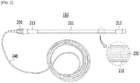
FIG. 2 , thefire extinguishing device 110 according to an embodiment includes a fire extinguishingtube container 210, afire extinguishing substance 220, and afire pre-sensor 230. - The fire extinguishing
tube container 210 includes thefire extinguishing substance 220 therein, and is configured to be able to automatically emit thefire extinguishing substance 220 when it is exposed to surrounding fire or heat. In an embodiment, the fire extinguishingtube container 210 may include acontainer body 211 and closingmembers 213 sealing the openings at both ends of thecontainer body 211. - The
container body 211 is formed in a cylindrical shape having an accommodation space therein. The accommodation space of thecontainer body 211 is filled with thefire extinguishing substance 220. The closingmember 213 is disposed at each of both ends of thecontainer body 211 such that thecontainer body 211 has a sealed structure. - The
container body 211 may be made of plastic-based polymers and is configured to be ruptured at a specific high temperature (temperature over 110°C□130°C) when a fire occurs such that thefire extinguishing substance 220 in the accommodation space can be discharged. - The
container body 211 may be formed in a tube shape, but is not limited thereto and may be formed in various shapes with various lengths, such as a stick or a hose, depending on the installation space. Thecontainer body 211 may be formed thin in about 1∼2mm thickness to be able to be quickly ruptured by heat when a fire occurs. - The covering
members 213 may be sealing caps that are fitted on both open ends of thecontainer body 211 and seal the open portions, respectively. The closingmembers 213 may be configured as parts of thecontainer 211 to naturally seal the open portions by thermally forming both ends of thecontainer body 211 that is open. Thermal forming is performed by a specific forming apparatus such that the center of thecontainer 211 is closed in a predetermined shape in a deformable temperature condition thereof and the closed center portion is made smooth through a melting process. Thefire pre-sensor 230 is installed on the closingmember 213. - The
fire extinguishing substance 220, which is in a liquid state and fills the accommodation space of thecontainer body 211, may be inert gas-based or halogen compound-based substances such as halon gas, nitrogen, and carbon dioxide, but is not limited thereto and may be a pure fire extinguishing agent that does not influence both of the environment and installed electrical equipment. Thefire extinguishing substance 220, as for the characteristics, has a boiling point lower than that of common water and expands with high pressure when temperature increases. Thefire extinguishing device 110 can estimate an increase of the external air temperature as an early sign of fire occurrence and can predict fire occurrence by measuring the internal pressure of the fire extinguishingtube container 210. - The
fire pre-sensor 230 is coupled to the closingmember 213 disposed at a side of thecontainer body 211 to sense early signs of a fire around thecontainer body 211. Thefire pre-sensor 230 may include a pressure sensor that measures the internal pressure of thecontainer body 211. Thefire pre-sensor 230 may be coupled to the closingmember 213 in a connector type and the pressure sensor for sensing internal pressure is fitted in the closingmember 213 to be connected to the accommodation space for thefire extinguishing substance 220 in thecontainer body 211. The pressure sensor is a device that senses the internal pressure of thecontainer body 211 that is in proportion to temperature to be able to predict an early sign of a fire due to an increase in temperature of the external air around thecontainer body 211. - A
connection line 240 may extend from thefire pre-sensor 230 and may be connected to a fire motor. The fire pre-sensor 230 can communicate with the fire monitor and can transmit fire-early sign information including the measured internal pressure of the fire extinguishingtube container 210 through theconnection line 240. -
FIG. 3 is a block diagram illustrating the physical configuration of the fire extinguishing device shown inFIG. 1 . - Referring to
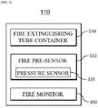
FIG. 3 , thefire extinguishing device 110 may include a fire extinguishingtube container 310, afire pre-sensor 330, and afire monitor 350. - The fire extinguishing
tube container 310 includes a fire extinguishing substance therein, and can automatically emit the fire extinguishing substance when it is exposed to surrounding fire or heat. To this end, the fire extinguishingtube container 310 may be made of a material in which a rupture hole for automatic emission can be formed when surrounding fire or heat increases. For example, the fire extinguishingtube container 310 may be made of a plastic-based material, whereby a side thereof can be ruptured and the substance therein can be emitted out of the container by internal pressure when surrounding fire or heat increases over 70 degrees. - The fire extinguishing
tube container 310 may be easily applied to a small space and may be fundamentally formed in a cylindrical shape, for the characteristics of the material, but may be easily changed in various shapes with various lengths. For example, the fire extinguishingtube container 310 may be installed in a space with a high possibility of fire occurrence such as a panel board in a building, and may be installed after a specific portion is bent, depending on the structure of a space. The fire extinguishingtube container 310 may be installed and fixed at the rack (metal frame) of an electrical facility box such as a panel board. - In an embodiment, the material of a specific region of the fire extinguishing
tube container 310 may be made of a material different from the material of the other region to induce rupture at the specific region when a fire occurs. For example, the middle region may be formed thinner than the other region of the fire extinguishingtube container 310 so that rupture is induced at the middle point, and a region corresponding to 1/3 or 2/3 of the entire length may be made of a material different from the material of the other region. That is, the material and thickness of the fire extinguishingtube container 310 may be different, depending on regions, to induce rupture at a predetermined point and a desired emission direction due to rupture. - In an embodiment, the fire extinguishing
tube container 310 can emit the fire extinguishing substance through a rupture hole that is formed in a specific region of the outer surface of the container when surrounding fire directly transfers to the outer surface of the container or surrounding heat indirectly transfers to the outer surface of the container. To this end, the fire extinguishingtube container 310 may be configured to be automatically ruptured when it is directly exposed to fire or the surrounding temperature increases over a specific temperature. It is possible to induce the rupture point or the emission direction into a specific point or a specific direction by adjusting the thickness or using different materials for regions of the fire extinguishingtube container 310. - The
fire pre-sensor 330 is connected to the fire extinguishingtube container 310 and can sense early signs of a fire around the installation position of thefire extinguishing device 110. In an embodiment, thefire pre-sensor 330 is coupled to an end of the fire extinguishingtube container 310 and can measure the internal pressure of the fire extinguishingtube container 310, and for this purpose, may include apressure sensor 331. Thepressure sensor 331 is connected to the inside of the fire extinguishingtube container 310 and can measure the pressure in the fire extinguishingtube container 310. Herein, internal pressure information means a change of the internal pressure of the fire extinguishingtube container 310 due to a change in temperature of the surrounding external air. Accordingly, the internal pressure information may correspond to the information about a temperature increase due to fire occurrence. That is, the internal pressure information measured by thefire pre-sensor 330 can be used to estimate the temperature in the space where the fire extinguishingtube container 310 is installed and to predict fire occurrence in advance while temperature continuously increases. - The fire pre-sensor 330 can sense an early sign of a fire by measuring the internal pressure of the fire extinguishing
tube container 310. Thefire pre-sensor 330 may include thepressure sensor 331, but is not limited thereto and may include various sensors, thereby being able to separately sense the factors of early signs of a fire. For example, thefire pre-sensor 330 may include a temperature sensor and a humidity sensor that can measure temperature and humidity of the external air around the fire extinguishingtube container 330, respectively, a flame sensor that senses generation of a spark, a smoke sensor that senses smoke, etc. The fire pre-sensor 330 can serve to obtain items of environmental information that are factors of early signs of a fire around the fire extinguishingtube container 310 by sensing the external environment such as temperature and humidity of external air and generation of a spark and smoke together with the internal space, that is, the internal pressure of the fire extinguishingtube container 310. - The fire monitor 350 may be installed at a predetermined distance from the fire extinguishing
tube container 310 on which thefire pre-sensor 330 is installed, and may be connected with thefire pre-sensor 330 in a wired or wireless type. The fire monitor 350 can create monitoring information for preventing and sensing a fire while collecting the state of the fire extinguishingtube container 310 through thefire pre-sensor 330. The fire monitor 350 may include a communication module for transmitting the information collected by the fire pre-sensor 330 to an external device. The fire monitor 350 may be connected with thefire prevention device 130 through a network and can transmit monitoring information in real time or periodically. - In an embodiment, the fire monitor 350 can monitor the state of the fire extinguishing
tube container 310 by controlling the operation of thepressure sensor 331 for measuring the internal pressure of the fire extinguishingtube container 310. The fire monitor 350 can sense in real time the internal pressure of the fire extinguishingtube container 310, and can provide an alert to an external system through a network when an early sign of a fire is sensed around the fire extinguishingtube container 310. The alert that is provided to the external system may be implemented and provided in various types such as a message, a voice, and vibration. The fire monitor 350 can store and keep the information about the internal pressure of the fire extinguishingtube container 310 in an internal memory, and can detect an abnormal signal out of a normal range from the information collected in the monitoring process and transmit relevant information to the external system. - In an embodiment, the fire monitor 350 can transmit monitoring information about the internal pressure and a variation of the internal pressure of the fire extinguishing
tube container 310 by monitoring in real time the fire extinguishingtube container 310. The fire monitor 350 can measure the internal pressure of the fire extinguishingtube container 310 and calculates a variation of the internal pressure that is a change of the internal pressure per unit time. - When the internal pressure of the fire extinguishing
tube container 310 increases over a specific critical value, the fire monitor 350 can determine it as an early sign of a fire, calculate the variation of the internal pressure for a specific time period including the point in time, classify the danger of a fire into caution, warning, and danger, etc., depending on the variation of the internal pressure, and generate an alarm for each of the fire danger step. In an embodiment, when the internal pressure of the fire extinguishingtube container 310 increases over a specific critical value, the fire monitor 350 can estimate that the temperature of the external air around the fire extinguishingtube container 310 has increased. Further, in this case, thefire monitor 350 calculates and compares the variation of the internal pressure for specific time periods before and after the point in time with a reference internal pressure range at a fire-possible external air temperature, thereby being able to determine the corresponding fire danger step. For example, the fire monitor 350 can determine a wire warning step when the variation of the internal pressure is in the reference internal pressure range, can determine a fire danger step when the variation is over the reference internal pressure range, and can determine a fire caution step when the variation is under the reference internal pressure range. - In an embodiment, when the internal pressure rapidly decreases while increasing, the fire monitor 350 can determine that the fire extinguishing
tube container 310 has been ruptured on the basis of the variation of the internal pressure of the fire extinguishingtube container 310 and can provide information about the rupture of the container by generating an alarm. When the fire extinguishingtube container 310 is ruptured, it can be considered as an automatic fire extinguishing state due to fire occurrence, so a following prevention operation can be performed in the external system. - The fire extinguishing substance in the fire extinguishing
tube container 310 may be naturally discharged over time, and accordingly, the internal pressure of the fire extinguishingtube container 310 may decrease. In this case, since it may be required to replace or check the fire extinguishingtube container 310, the fire monitor 350 can inform a manager or a checker of this situation in advance by generating an alarm. -
FIG. 4 is a flowchart illustrating an embodiment of a fire prediction operation that is performed by the fire extinguishing device shown inFIG. 3 . - Referring to
FIG. 4 , thefire extinguishing device 110 can be installed around a fire-extinguishing target, can sense early signs of a fire around the fire extinguishingtube container 310 through thefire pre-sensor 330, can be connected with an external system through thefire monitor 350, and can provide an alert. In more detail, thefire pre-sensor 330 can be installed on a side of the fire extinguishingtube container 310 and can measure the internal pressure of the fire extinguishingtube container 310 in real time through thepressure sensor 331 connected to the inside of the fire extinguishing tube container 310 (step S410). - The fire monitor 350 can estimate a continuous increase of the temperature of the external air around the fire extinguishing
tube container 310 and can predict early signs of a fire and rupture of the fire extinguishing tube container by analyzing whether the internal pressure of the fire extinguishingtube container 310, which is measured in real time by thepressure sensor 331 of thefire pre-sensor 330, changes over time (step S430). - When the estimated temperature of the external air increases over a specific critical value, that is, when the internal pressure increases over a specific critical value, the
fire monitor 350 calculates the variation of the internal pressure, classifies the fire danger steps on the basis of the variation of the internal pressure, and provides an alert to the outside through a network. Further, when rupture of the fire extinguishingtube container 310 is predicted, thefire monitor 350 generates an alarm to enable a manager to take measures (step S450). - Although the present disclosure was described above with reference to exemplary embodiments, it should be understood that the present disclosure may be changed and modified in various ways by those skilled in the art, without departing from the spirit and scope of the present disclosure described in claims.
-
- 100: fire extinguishing system with a fire prediction function
- 110: fire extinguishing device 130: fire prevention device
- 150: database 170: user terminal
- 210, 310: fire extinguishing tube container
- 211: container body 213: closing member
- 220:
fire extinguishing substance 230, 330: fire pre-sensor - 240: connection line
- 331: pressure sensor
- 350: fire monitor
Claims (8)
- A fire extinguishing device with a fire prediction function, the fire extinguishing device comprising:a fire extinguishing tube container including a fire extinguishing substance therein, and automatically emitting the fire extinguishing substance when being exposed to surrounding fire or heat; anda fire pre-sensor coupled to a side of the fire extinguishing tube container and sensing a surrounding early sign of a fire by measuring an internal pressure of the fire extinguishing tube container.
- The fire extinguishing device of claim 1, wherein the fire extinguishing tube container includes:a container body having a predetermined length, formed in a tube shape, and having a space therein filled with the fire extinguishing substance; anda closing member disposed at both ends of the container, respectively, and sealing the container body.
- The fire extinguishing device of claim 2, wherein the closing members are sealing caps fitted on both open ends of the container body and sealing open portions, respectively.
- The fire extinguishing device of claim 1, wherein when the surrounding fire of the fire extinguishing tube container directly transfers to the outer surface of the container or the surrounding heat indirectly transfers to the outer surface of the container, the fire extinguishing substance is emitted through a rupture hole that is formed in a specific region of the outer surface of the container.
- The fire extinguishing device of claim 2, wherein the fire pre-sensor includes a pressure sensor coupled to the closing member installed on a side of the container body, and measuring the internal pressure of the container body in real time.
- The fire extinguishing device of claim 5, wherein the fire pre-sensor is fitted on the closing member such that the pressure sensor is connected to the inside of the container body, and senses the internal pressure of the container body that expands, depending on the temperature of external air around the container body.
- The fire extinguishing device of claim 6, further comprising a fire monitor connected with the fire pre-sensor and generating monitoring information while collecting an internal state of the fire extinguishing tube container and external environmental information,
wherein the fire monitor estimates a continuous increase of the temperature of the external air around the fire extinguishing tube container and predicts early signs of a fire and rupture of the fire extinguishing tube container by analyzing whether the internal pressure of the fire extinguishing tube container, which is measured in real time by the pressure sensor, changes over time. - The fire extinguishing device of claim 7, wherein the fire monitor calculates a variation of the internal pressure, classifies fire danger steps on the basis of the variation of the internal pressure, and provides an alert to the outside when the internal pressure of the fire extinguishing tube container increases over a specific critical value; and generates an alarm for a manager to take measures when rupture of the fire extinguishing tube container is predicted.
Applications Claiming Priority (2)
| Application Number | Priority Date | Filing Date | Title |
|---|---|---|---|
| KR1020200057115A KR102228765B1 (en) | 2020-05-13 | 2020-05-13 | Fire extinguishing devices with fire predicting function |
| PCT/KR2021/005249 WO2021230531A1 (en) | 2020-05-13 | 2021-04-26 | Fire extinguishing apparatus having fire prediction function |
Publications (2)
| Publication Number | Publication Date |
|---|---|
| EP3936196A1 true EP3936196A1 (en) | 2022-01-12 |
| EP3936196A4 EP3936196A4 (en) | 2022-10-05 |
Family
ID=75232365
Family Applications (1)
| Application Number | Title | Priority Date | Filing Date |
|---|---|---|---|
| EP21740421.9A Pending EP3936196A4 (en) | 2020-05-13 | 2021-04-26 | Fire extinguishing apparatus having fire prediction function |
Country Status (4)
| Country | Link |
|---|---|
| EP (1) | EP3936196A4 (en) |
| KR (2) | KR102228765B1 (en) |
| CN (1) | CN113939345A (en) |
| WO (1) | WO2021230531A1 (en) |
Families Citing this family (1)
| Publication number | Priority date | Publication date | Assignee | Title |
|---|---|---|---|---|
| KR102228765B1 (en) * | 2020-05-13 | 2021-03-18 | (주)일선시스템 | Fire extinguishing devices with fire predicting function |
Family Cites Families (14)
| Publication number | Priority date | Publication date | Assignee | Title |
|---|---|---|---|---|
| GB8926849D0 (en) * | 1989-11-28 | 1990-01-17 | Melton David L | Fire extinguisher |
| KR20040027534A (en) * | 2004-02-10 | 2004-04-01 | 정재묵 | Linear Fire Tube and Non-Power Automatic Fire System |
| KR100773517B1 (en) | 2005-06-28 | 2007-11-06 | 주식회사 건국이엔아이 | A sensing and monitoring device of fire extinguishing chemical in a fire extinguisher |
| JP2011004884A (en) * | 2009-06-24 | 2011-01-13 | Panasonic Electric Works Co Ltd | Extinguishant and flammable liquid containing extinguishing gas |
| KR101170083B1 (en) * | 2012-06-27 | 2012-07-31 | 상원엔지니어링(주) | Automatic fire extinguisher for cabinet panel |
| JP3179000U (en) * | 2012-07-30 | 2012-10-11 | 株式会社ニチボウ | Automatic fire extinguisher |
| KR101286756B1 (en) * | 2012-11-22 | 2013-07-16 | 주식회사 테크노믹스 | A fire extinguishing device |
| KR101754620B1 (en) * | 2016-07-18 | 2017-07-06 | (주)우송엔지니어링 | Fire remote management system |
| KR101796118B1 (en) * | 2017-02-17 | 2017-11-10 | 주식회사 파라텍 | System and method for monitoring the gas leakage of fire extinguisher |
| KR101853631B1 (en) * | 2017-06-30 | 2018-05-02 | 상원엔지니어링(주) | Automatic fire extinguishing system with multiple monitoring and selective fire extinguish |
| KR101918896B1 (en) * | 2018-05-28 | 2018-11-14 | 주식회사 지아체시스템즈 | automatic control panel box |
| CN110600817A (en) * | 2019-08-16 | 2019-12-20 | 中国科学技术大学 | A withstand voltage test device for lithium ion battery thermal runaway danger research |
| CN111001109A (en) * | 2019-11-11 | 2020-04-14 | 北京理工大学 | Extinguishing device, battery box and electric automobile |
| KR102228765B1 (en) * | 2020-05-13 | 2021-03-18 | (주)일선시스템 | Fire extinguishing devices with fire predicting function |
-
2020
- 2020-05-13 KR KR1020200057115A patent/KR102228765B1/en active IP Right Grant
-
2021
- 2021-03-05 KR KR1020210029233A patent/KR102378243B1/en active IP Right Grant
- 2021-04-26 CN CN202180002131.1A patent/CN113939345A/en active Pending
- 2021-04-26 EP EP21740421.9A patent/EP3936196A4/en active Pending
- 2021-04-26 WO PCT/KR2021/005249 patent/WO2021230531A1/en unknown
Also Published As
| Publication number | Publication date |
|---|---|
| KR20210139131A (en) | 2021-11-22 |
| EP3936196A4 (en) | 2022-10-05 |
| KR102378243B1 (en) | 2022-03-25 |
| WO2021230531A1 (en) | 2021-11-18 |
| KR102228765B1 (en) | 2021-03-18 |
| CN113939345A (en) | 2022-01-14 |
Similar Documents
| Publication | Publication Date | Title |
|---|---|---|
| KR102197304B1 (en) | Integrated fire protection apparatus and method using iot-based fire extinguishing devices | |
| EP2543026B1 (en) | Aspirating environmental sensor with webserver and email notification | |
| KR101439860B1 (en) | Sensing System and Method for fire in realtime | |
| WO2008105578A1 (en) | System for monitoring industrial disaster in the manufacturing industry | |
| KR101811393B1 (en) | Remote Control System for Automatic Fire Alarm Equiment | |
| CN103744357A (en) | Laboratory safety wireless monitoring method and system | |
| CN110689698A (en) | Community fire early warning and escape system and prompting method thereof | |
| KR20160010896A (en) | Smart fire-fighting management system for cultural assets and method thereof | |
| EP3936196A1 (en) | Fire extinguishing apparatus having fire prediction function | |
| KR102040431B1 (en) | System for fire defense management and method for preventing malfunction in the same | |
| KR102301794B1 (en) | Building fire detection automatic report system | |
| CN114360194A (en) | Multi-point monitoring visual phased array type fire alarm system | |
| KR102132288B1 (en) | Fire extinguishing device with iot function | |
| KR100596204B1 (en) | Multi detecting system for fire signatures of rack | |
| US20230264057A1 (en) | Fire extinguishing devices with fire predicting function | |
| Rajalakshmi et al. | Smart Gas System | |
| CN212135613U (en) | Building fire alarm device | |
| KR101750747B1 (en) | Electronic fire detector by bluetooth ibeacon transmitter and receiving system | |
| CN113393635B (en) | Fire early warning detection system based on temperature sensing optical fiber | |
| JP2022150911A (en) | Fire extinguishing system and fire extinguishing method for rechargeable battery facility room | |
| KR20220075812A (en) | Method and system for managing a fire of power converter | |
| KR102708677B1 (en) | Automatic Fire Extinguishing System with IP Address Verification Function | |
| WO2011002160A2 (en) | Apparatus for signaling fire danger utilizing indoor pressure fluctuation | |
| CN221040225U (en) | Safety power consumption monitoring device | |
| CN212990273U (en) | Ganbaosu production system with explosion-proof detection function |
Legal Events
| Date | Code | Title | Description |
|---|---|---|---|
| STAA | Information on the status of an ep patent application or granted ep patent |
Free format text: STATUS: UNKNOWN |
|
| STAA | Information on the status of an ep patent application or granted ep patent |
Free format text: STATUS: THE INTERNATIONAL PUBLICATION HAS BEEN MADE |
|
| PUAI | Public reference made under article 153(3) epc to a published international application that has entered the european phase |
Free format text: ORIGINAL CODE: 0009012 |
|
| STAA | Information on the status of an ep patent application or granted ep patent |
Free format text: STATUS: REQUEST FOR EXAMINATION WAS MADE |
|
| 17P | Request for examination filed |
Effective date: 20210723 |
|
| AK | Designated contracting states |
Kind code of ref document: A1 Designated state(s): AL AT BE BG CH CY CZ DE DK EE ES FI FR GB GR HR HU IE IS IT LI LT LU LV MC MK MT NL NO PL PT RO RS SE SI SK SM TR |
|
| A4 | Supplementary search report drawn up and despatched |
Effective date: 20220906 |
|
| RIC1 | Information provided on ipc code assigned before grant |
Ipc: G08B 17/04 20060101ALI20220831BHEP Ipc: A62C 37/38 20060101ALI20220831BHEP Ipc: A62C 37/11 20060101ALI20220831BHEP Ipc: A62C 3/16 20060101ALI20220831BHEP Ipc: G01L 17/00 20060101ALI20220831BHEP Ipc: G08B 25/14 20060101ALI20220831BHEP Ipc: G08B 17/00 20060101ALI20220831BHEP Ipc: A62C 35/10 20060101AFI20220831BHEP |
|
| DAV | Request for validation of the european patent (deleted) | ||
| DAX | Request for extension of the european patent (deleted) |