EP3936059A2 - Perkutane vorrichtung zum verschliessen eines blutgefässes - Google Patents
Perkutane vorrichtung zum verschliessen eines blutgefässes Download PDFInfo
- Publication number
- EP3936059A2 EP3936059A2 EP21181367.0A EP21181367A EP3936059A2 EP 3936059 A2 EP3936059 A2 EP 3936059A2 EP 21181367 A EP21181367 A EP 21181367A EP 3936059 A2 EP3936059 A2 EP 3936059A2
- Authority
- EP
- European Patent Office
- Prior art keywords
- tie rod
- clip
- distal
- proximal
- percutaneous device
- Prior art date
- Legal status (The legal status is an assumption and is not a legal conclusion. Google has not performed a legal analysis and makes no representation as to the accuracy of the status listed.)
- Pending
Links
Images






Classifications
-
- A—HUMAN NECESSITIES
- A61—MEDICAL OR VETERINARY SCIENCE; HYGIENE
- A61B—DIAGNOSIS; SURGERY; IDENTIFICATION
- A61B17/00—Surgical instruments, devices or methods
- A61B17/04—Surgical instruments, devices or methods for suturing wounds; Holders or packages for needles or suture materials
- A61B17/0467—Instruments for cutting sutures
-
- A—HUMAN NECESSITIES
- A61—MEDICAL OR VETERINARY SCIENCE; HYGIENE
- A61B—DIAGNOSIS; SURGERY; IDENTIFICATION
- A61B17/00—Surgical instruments, devices or methods
- A61B17/04—Surgical instruments, devices or methods for suturing wounds; Holders or packages for needles or suture materials
- A61B17/0401—Suture anchors, buttons or pledgets, i.e. means for attaching sutures to bone, cartilage or soft tissue; Instruments for applying or removing suture anchors
-
- A—HUMAN NECESSITIES
- A61—MEDICAL OR VETERINARY SCIENCE; HYGIENE
- A61B—DIAGNOSIS; SURGERY; IDENTIFICATION
- A61B17/00—Surgical instruments, devices or methods
- A61B17/04—Surgical instruments, devices or methods for suturing wounds; Holders or packages for needles or suture materials
- A61B17/0487—Suture clamps, clips or locks, e.g. for replacing suture knots; Instruments for applying or removing suture clamps, clips or locks
-
- A—HUMAN NECESSITIES
- A61—MEDICAL OR VETERINARY SCIENCE; HYGIENE
- A61B—DIAGNOSIS; SURGERY; IDENTIFICATION
- A61B17/00—Surgical instruments, devices or methods
- A61B17/12—Surgical instruments, devices or methods for ligaturing or otherwise compressing tubular parts of the body, e.g. blood vessels or umbilical cord
- A61B17/12009—Implements for ligaturing other than by clamps or clips, e.g. using a loop with a slip knot
- A61B17/12013—Implements for ligaturing other than by clamps or clips, e.g. using a loop with a slip knot for use in minimally invasive surgery, e.g. endoscopic surgery
-
- A—HUMAN NECESSITIES
- A61—MEDICAL OR VETERINARY SCIENCE; HYGIENE
- A61B—DIAGNOSIS; SURGERY; IDENTIFICATION
- A61B17/00—Surgical instruments, devices or methods
- A61B2017/00004—(bio)absorbable, (bio)resorbable or resorptive
-
- A—HUMAN NECESSITIES
- A61—MEDICAL OR VETERINARY SCIENCE; HYGIENE
- A61B—DIAGNOSIS; SURGERY; IDENTIFICATION
- A61B17/00—Surgical instruments, devices or methods
- A61B2017/00743—Type of operation; Specification of treatment sites
- A61B2017/00778—Operations on blood vessels
-
- A—HUMAN NECESSITIES
- A61—MEDICAL OR VETERINARY SCIENCE; HYGIENE
- A61B—DIAGNOSIS; SURGERY; IDENTIFICATION
- A61B17/00—Surgical instruments, devices or methods
- A61B17/04—Surgical instruments, devices or methods for suturing wounds; Holders or packages for needles or suture materials
- A61B17/0401—Suture anchors, buttons or pledgets, i.e. means for attaching sutures to bone, cartilage or soft tissue; Instruments for applying or removing suture anchors
- A61B2017/0409—Instruments for applying suture anchors
-
- A—HUMAN NECESSITIES
- A61—MEDICAL OR VETERINARY SCIENCE; HYGIENE
- A61B—DIAGNOSIS; SURGERY; IDENTIFICATION
- A61B17/00—Surgical instruments, devices or methods
- A61B17/04—Surgical instruments, devices or methods for suturing wounds; Holders or packages for needles or suture materials
- A61B17/0401—Suture anchors, buttons or pledgets, i.e. means for attaching sutures to bone, cartilage or soft tissue; Instruments for applying or removing suture anchors
- A61B2017/0417—T-fasteners
-
- A—HUMAN NECESSITIES
- A61—MEDICAL OR VETERINARY SCIENCE; HYGIENE
- A61B—DIAGNOSIS; SURGERY; IDENTIFICATION
- A61B17/00—Surgical instruments, devices or methods
- A61B17/04—Surgical instruments, devices or methods for suturing wounds; Holders or packages for needles or suture materials
- A61B17/0401—Suture anchors, buttons or pledgets, i.e. means for attaching sutures to bone, cartilage or soft tissue; Instruments for applying or removing suture anchors
- A61B2017/0446—Means for attaching and blocking the suture in the suture anchor
- A61B2017/0448—Additional elements on or within the anchor
- A61B2017/0451—Cams or wedges holding the suture by friction
-
- A—HUMAN NECESSITIES
- A61—MEDICAL OR VETERINARY SCIENCE; HYGIENE
- A61B—DIAGNOSIS; SURGERY; IDENTIFICATION
- A61B17/00—Surgical instruments, devices or methods
- A61B17/04—Surgical instruments, devices or methods for suturing wounds; Holders or packages for needles or suture materials
- A61B17/0401—Suture anchors, buttons or pledgets, i.e. means for attaching sutures to bone, cartilage or soft tissue; Instruments for applying or removing suture anchors
- A61B2017/0464—Suture anchors, buttons or pledgets, i.e. means for attaching sutures to bone, cartilage or soft tissue; Instruments for applying or removing suture anchors for soft tissue
-
- A—HUMAN NECESSITIES
- A61—MEDICAL OR VETERINARY SCIENCE; HYGIENE
- A61B—DIAGNOSIS; SURGERY; IDENTIFICATION
- A61B17/00—Surgical instruments, devices or methods
- A61B17/04—Surgical instruments, devices or methods for suturing wounds; Holders or packages for needles or suture materials
- A61B17/0469—Suturing instruments for use in minimally invasive surgery, e.g. endoscopic surgery
- A61B2017/0474—Knot pushers
-
- A—HUMAN NECESSITIES
- A61—MEDICAL OR VETERINARY SCIENCE; HYGIENE
- A61B—DIAGNOSIS; SURGERY; IDENTIFICATION
- A61B90/00—Instruments, implements or accessories specially adapted for surgery or diagnosis and not covered by any of the groups A61B1/00 - A61B50/00, e.g. for luxation treatment or for protecting wound edges
- A61B90/03—Automatic limiting or abutting means, e.g. for safety
- A61B2090/037—Automatic limiting or abutting means, e.g. for safety with a frangible part, e.g. by reduced diameter
Definitions
- the subject of the present invention is a device for interrupting the function of superficial venous collectors, using percutaneous access and ultrasonic guidance.
- the short venous site which, in the event of over- or under-treatment, may place the patient at risk of thrombosis that extends to deep circulation or central embolism and at risk of more or less extensive recanalization of the vessel by blood reflux, with recurrence of the varicose syndrome.
- the object of this invention is to provide a percutaneous device for interrupting the function of venous collectors that makes it possible to mechanically occlude a venous vessel by means of transcutaneous puncture access.
- the device according to this invention makes it possible to carry out operations to intercept and/or close a blood vessel using percutaneous access in a simplified manner, which requires reduced manual ability which is not necessarily surgical. As a result, the operating times and the impact on patient approval acceptance (or compliance) are drastically reduced by comparison with "open" surgery techniques.
- Reference sign 100 represents a percutaneous device for interrupting the function of superficial venous collectors according to this invention. This device is suitable for intercepting and closing a blood vessel, for example the saphenous vein.
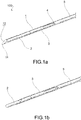
- the device 100 comprises a main body 1 which extends along a longitudinal axis X and is internally hollow in order to house a pair of clamping clips 2, 3 and an abutment element 5 for the clips 2, 3.
- the main body 1 is preferably a metal cannula which may be inserted percutaneously, and is provided with a distal perforation tip 11, for example in the form of a needle.
- the distal tip 11 comprises a distal opening 12 from which the clips 2, 3 exit.
- the abutment element 5 is preferably a rod which is cylindrical, elliptical or semi-circular.
- the abutment element 5 extends along the longitudinal axis X and is provided with a passageway for the tie rod 4.
- the passageway for the tie rod 4 is, for example, a central hole such that the tie rod 4 slides internally in the abutment element 5, or a lateral groove such that the tie rod 4 slides externally to the abutment element 5.
- the abutment element 5 is provided with a distal end 51 adapted to push the proximal clip 3.
- the device 100 preferably comprises a handle 7 which is connected to the proximal portion of the main body 1 and is adapted to maneuver the clips 2, 3 and the tie rod 4.
- the overall configuration of the device 100 is such that the pair of clamping clips 2, 3 and the abutment element 5 may be slidably inserted inside the main body 1, may exit from the distal opening 12, and may be maneuvered from the outside by means of the handle 7. It should be noted that the abutment element 5 is integral with the handle 7.
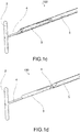
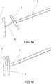
- the pair of clips comprises a distal clip 2 for intercepting the vessel and a proximal clip 3 for clamping the vessel.
- the clips 2, 3 are preferably substantially in the form of a bar or rod, i.e. have a cylindrical and elongate shape.
- Each clip 2, 3 preferably has a length determined by the specific surgical requirements and by the dimensions of the vessel to be treated, for example in a range of approximately 6-12 mm.
- the clips 2, 3 may be the same length or may be different lengths.
- the clips 2, 3 are preferably made of biocompatible metal material or made of bioresorbable material.
- the clips 2, 3 are connected to each other by means of a tie rod 4 or an equivalent means.
- the tie rod 4 has a substantially circular or semi-circular cross section.
- the tie rod 4 has a flattened cross section or is substantially a tape.
- the tie rod 4 has a flattened cross section distally, preferably between the two clips 2, 3, and then continues with a circular cross section proximally.
- the tie rod 4 has a flattened cross section for a distal length between the length of half a clip and the length of two clips.
- the tie rod 4 is preferably made of nylon or polyester or is made of resorbable material.
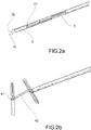
- the clips 2, 3 are provided with a seat 21, 31 into which the tie rod 4 is inserted.
- the distal clip 2 is provided with a distal seat 21 into which the tie rod 4 is fastened.
- the distal seat 21 is preferably a through hole which has a circular ( Fig. 3 and 5 ) or rectangular cross section.
- the distal seat 21 preferably transversely crosses the distal clip 2 perpendicularly. This solution makes it possible to correctly orient and turn over the distal clip 2 once it has been released.
- the proximal clip 3 is provided with a proximal seat 31 into which the tie rod 4 is slidably inserted.
- the proximal seat 31 is preferably a through hole which has a circular ( Fig. 7A ) or oval ( Fig. 7B ) or rectangular ( Fig. 10A ) cross section.
- the proximal seat 31 preferably transversely crosses the proximal clip 3 obliquely. This solution makes it possible both to correctly orient the proximal clip 3 once it has been released and to correctly slide the tie rod 4.
- a distal end 41 of the tie rod 4 is fastened in the seat 21 of the distal clip 2, the tie rod 4 is also slidably inserted in the seat 31 of the proximal clip 3 such that an intermediate portion 42 of the tie rod 4 is arranged between the clips 2, 3, and a proximal end 43 of the tie rod 4 may be maneuvered by the surgeon, either directly or by means of a handle 7.
- the tie rod 4 and the clips 2, 3 may be made of non-resorbable or resorbable material.
- the clips 2, 3 preferably have transverse dimensions (i.e. a diameter) so as to be able to slide freely, possibly with minimal friction in order to prevent slipping, inside the main body 1.
- the longitudinal axis of the clips 2, 3 is in line with the longitudinal axis of the main body 1.
- One essential aspect for the correct functioning of the device 100 is the positioning of the tie rod 4 inside the main body 1, which tie rod must not interfere with the correct sliding of the clips 2, 3.
- the clips 2, 3 are therefore provided with at least one housing 22, 32, 33 in which the tie rod 4 is positioned when the clips 2, 3 are inside the main body 1.
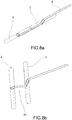
- the housing 22, 32, 33 is a longitudinal groove formed on the outer surface of the clip 2, 3 such that the tie rod 4 is inserted into this groove and therefore fits inside the volume of space occupied by the clip 2, 3, as may be seen in Fig. 1A , 2A and 8A .
- the distal clip 2 is provided with a proximal housing 22, and optionally also a distal housing for fastening the tie rod.
- the proximal clip 3 is provided with both a distal housing 32 and a proximal housing 33.
- distal housing and the proximal housing are arranged on opposite sides of the clip.
- the housing 22, 32, 33 has a rectangular or square or U-shaped cross section.
- the housing 22, 32, 33 has a triangular or V-shaped cross section.
- the housing 22, 32, 33 is a longitudinal flattened portion or a C-shaped or crescent-shaped recess.
- the housing 22, 32, 33 comprises an inlet end to the clip 2, 3 and an end that traverses the clip 2, 3 and flows into the seat 21, 31.
- the distal clip 2 therefore comprises a path for the tie rod 4 that starts from the seat 21 and continues along the housing 22.
- the path for the tie rod 4 occupies approximately half of the length of the distal clip 2.
- the distal clip 2 also comprises a distal housing used as a further compartment (in addition to the seat 21) for fastening the tie rod 4.
- the distal clip 2 comprises a path for the tie rod 4 that starts from the distal housing and continues into the seat 21 through the clip in order to exit from the opposite side and continue along the housing 22.
- the path for the tie rod 4 therefore occupies more than half of the length of the distal clip 2.
- the proximal clip 3 comprises a path for the tie rod 4 that starts from the housing 32 and continues into the seat 31 through the clip in order to exit from the opposite side and continue along the housing 33.
- the path for the tie rod 4 occupies the entire length of the proximal clip 3.
- the seat 21, 31 into which the tie rod 4 is inserted is rectangular and may be arranged longitudinally or transversely with respect to the clip 2, 3.
- the housing 22, 32, 33 in which the tie rod 4 is positioned when the clips 2, 3 are inside the main body 1 may be C-shaped or crescent-shaped.
- the device 100 comprises a handle 7 which extends predominantly longitudinally, is formed by two half-shells mechanically connected together, and is connected to the proximal portion of the main body 1.
- the handle 7 comprises a handle body 71 provided with a track 73 in which an operating lever 72 for operating the clips 2, 3 and the tie rod 4 is slidably accommodated.
- the operating lever 72 which may be seen in detail in Fig. 16A , extends predominantly longitudinally and preferably comprises a slider 721 which is shaped so as to facilitate gripping said slider and sliding it inside the track 73.
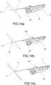
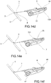
- the main body 1 is integral with the operating lever 72, which means that retracting the operating lever 72 also retracts the main body 1, as for example in Fig. 12B and 14B .
- the operating lever 72 comprises at least one seat 722 for the passageway of the tie rod 4, such that the lever may slide on the tie rod 4.
- the operating lever 72 comprises, at the rear, a lever stop 725 adapted to abut against a relevant tie rod stop 45 such that the operating lever 72 becomes integral with the tie rod 4 and such that retracting the operating lever 72 also retracts the tie rod 4, as may be seen in Fig. 12D and 14D .
- the handle 7 comprises a handle stop 75 adapted to abut against the lever stop 725 or against the slider 721 such that the operating lever 72 may not be retracted any further, as may be seen in Fig. 12E and 14E .
- the tie rod 4 is also provided with a traction element adapted to pull the tie rod 4 with respect to the handle 7.
- the traction element 45 is connected to the proximal end 43 of the tie rod 4.
- the traction element 45 at least partially exits the handle 7 in order to be gripped and optionally pulled by the medical professional, as in Fig. 12F .
- the traction element is a wheel 47 connected to the proximal end 43 of the tie rod 4.
- the wheel 47 at least partially exits from the handle 7 in order to be optionally rotated by the medical professional, as in Fig. 14F .
- the operating lever 72 comprises, in proximity to the slider 721, a cutting button 723 provided with a blade 724 adapted to sever the tie rod 4.
- the cutting button 723 is vertically slidable between a rest position ( Fig. 16A ) in which the blade 724 is spaced apart from the tie rod 4 and a cutting position ( Fig. 16B ) in which the blade 724 is pushed against the tie rod 4 in order to sever it.
- the tie rod 4 is provided, proximally with respect to the proximal clip 3, with a predetermined breaking point 44, for example a pre-incision or a weakened portion, that is adapted to yield in response to a certain traction force exerted on the tie rod 4.
- Said predetermined breaking point 44 is a calibrated point of weakness that makes it possible to only release the pair of clips after an optimal traction force has been exerted, in order to clamp and therefore occlude the vessel. This solution allows as little of the tie rod 4 as possible to be left inside the body of the patient after the vessel has been closed, as shown in Fig. 15B .
- the sequence of figures from 12A to 12F and from 14A to 14F shows the use of the device 100 in order to close a blood vessel.
- the main body 1 is introduced percutaneously by means of the needle tip 11.
- the tip 11 punctures the wall of the blood vessel V and passes through said vessel from one side to the other.
- the longitudinal axis of the clips 2, 3 is in line with the longitudinal axis of the main body 1.
- the distal clip 2 and with it also part of the tie rod 4, is made to exit from the distal opening 12 in the main body 1.
- the distal clip 2 is made to exit by retracting the operating lever 72 and the main body 1 therewith, while keeping the proximal clip 3 and the abutment element 5 in position.
- the tie rod 4 is then pulled, as may be seen in Fig. 12C and 14C , by pulling the handle 7, in order to correctly position the distal clip 2 against the outer wall of the vessel V.
- the distal clip 2 is arranged externally and substantially transversely with respect to the main body 1. Ultrasonic checks are used to verify that the distal clip 2 is abutting transversely against the distal wall of the blood vessel V.
- the proximal clip 3, and with it also part of the tie rod 4, is also made to exit the distal opening 12 in the main body 1 in the same manner as the distal clip 2.
- the proximal clip 3 is made to exit by retracting the operating lever 72 and the main body 1 therewith, while keeping the abutment element 5 in position.
- the tie rod 4 is then pulled, as may be seen in Fig. 12E and 14E , by pulling the handle 7, in order to correctly position the proximal clip 3 against the outer wall of the vessel V.
- the proximal clip 3 is also arranged externally and substantially transversely with respect to the main body 1.
- the tie rod 4 is also pulled, as may be seen in Fig. 12F and 14F , in order to correctly clamp the vessel between the distal clip 2 and the proximal clip 3.
- the tie rod 4 is optionally pulled by means of the traction element 45 or by rotating the wheel 47.
- tie rod slides into the seat 21 of the proximal clip 3 with a calibrated friction that allows the clips 2, 3 to clamp.
- the tie rod 4 is preferably provided with a radial dimension, for example a flattened portion or a thickened portion in a proximal position, so as to prevent the tie rod from being able to reenter the seat 31 of the proximal clip 3 once this radial dimension has exited therefrom.
- This solution makes it possible to maintain the correct clamping of the vessel between the distal clip 2 and the proximal clip 3, thus avoiding the need to produce a node on the tie rod that has to be pushed into position.
- a percutaneous device innovatively makes it possible to carry out operations to intercept and/or close a blood vessel percutaneously in a simplified manner, which requires reduced manual ability which is not necessarily surgical.
- the tie rod 4 advantageously does not interfere with the correct sliding of the clips 2, 3 inside the main body 1.
- the percutaneous device advantageously makes it possible to implement a mechanical method for closing a vein, or in general a blood vessel, even a large-caliber vessel, by means of closing or "clamping" on the outer wall of the blood vessel, which method is carried out percutaneously. It is therefore possible to perform ultrasound-guided obstruction of a vein by means of percutaneous clamping.
- the clips 2, 3 may advantageously be made of resorbable material, and may remain in position in order to guarantee the interruption of the venous blood flow while not interrupting the anatomical continuity of the vascular structure.
- the device according to this invention advantageously has various fields of application such as: superficial venous insufficiency; any case in which it is necessary to "ligate” or interrupt a venous tract; sapheno-femoral crossectomy; sapheno-popliteal crossectomy; interruption of varicose collaterals; interruption of incontinent perforating veins; segmentation of the saphenous reflux.
- the process may advantageously be intended as a simple isolated surgical procedure carried out on one or more sites, or may be a process carried out in association with other operations.
- An example of this is the interruption of the sapheno-femoral junction carried out in association with a procedure to ablate the great saphenous vein that is carried out using physical or chemical techniques.
Landscapes
- Health & Medical Sciences (AREA)
- Surgery (AREA)
- Life Sciences & Earth Sciences (AREA)
- Medical Informatics (AREA)
- Nuclear Medicine, Radiotherapy & Molecular Imaging (AREA)
- Engineering & Computer Science (AREA)
- Biomedical Technology (AREA)
- Heart & Thoracic Surgery (AREA)
- Molecular Biology (AREA)
- Animal Behavior & Ethology (AREA)
- General Health & Medical Sciences (AREA)
- Public Health (AREA)
- Veterinary Medicine (AREA)
- Rheumatology (AREA)
- Surgical Instruments (AREA)
- Medical Preparation Storing Or Oral Administration Devices (AREA)
Applications Claiming Priority (1)
| Application Number | Priority Date | Filing Date | Title |
|---|---|---|---|
| IT102020000016426A IT202000016426A1 (it) | 2020-07-07 | 2020-07-07 | Dispositivo percutaneo per il serraggio di un vaso sanguigno |
Publications (2)
| Publication Number | Publication Date |
|---|---|
| EP3936059A2 true EP3936059A2 (de) | 2022-01-12 |
| EP3936059A3 EP3936059A3 (de) | 2022-03-16 |
Family
ID=72644685
Family Applications (1)
| Application Number | Title | Priority Date | Filing Date |
|---|---|---|---|
| EP21181367.0A Pending EP3936059A3 (de) | 2020-07-07 | 2021-06-24 | Perkutane vorrichtung zum verschliessen eines blutgefässes |
Country Status (2)
| Country | Link |
|---|---|
| EP (1) | EP3936059A3 (de) |
| IT (1) | IT202000016426A1 (de) |
Cited By (2)
| Publication number | Priority date | Publication date | Assignee | Title |
|---|---|---|---|---|
| EP4197459A1 (de) * | 2021-12-15 | 2023-06-21 | Vcd Medical S.R.L. | Perkutane vorrichtung zum verschliessen eines blutgefässes |
| WO2024241145A1 (en) * | 2023-05-19 | 2024-11-28 | Vcd Medical S.R.L. | Improved percutaneous device for clamping a blood vessel |
Family Cites Families (5)
| Publication number | Priority date | Publication date | Assignee | Title |
|---|---|---|---|---|
| US9173647B2 (en) * | 2004-10-26 | 2015-11-03 | P Tech, Llc | Tissue fixation system |
| US7645286B2 (en) * | 2005-05-20 | 2010-01-12 | Neotract, Inc. | Devices, systems and methods for retracting, lifting, compressing, supporting or repositioning tissues or anatomical structures |
| US20130046331A1 (en) * | 2009-04-30 | 2013-02-21 | Mayo Foundation For Medical Education And Research | Body lumen occlusion apparatus and methods |
| WO2014102767A2 (en) * | 2012-12-27 | 2014-07-03 | Javelin Medical Ltd. | Apparatus and method of monofilament implant delivery in a body vessel of a patient |
| ES2653974B2 (es) * | 2017-10-20 | 2018-10-25 | Ramón CANET TORRES | Horma articulada para trabajo con calzado |
-
2020
- 2020-07-07 IT IT102020000016426A patent/IT202000016426A1/it unknown
-
2021
- 2021-06-24 EP EP21181367.0A patent/EP3936059A3/de active Pending
Cited By (2)
| Publication number | Priority date | Publication date | Assignee | Title |
|---|---|---|---|---|
| EP4197459A1 (de) * | 2021-12-15 | 2023-06-21 | Vcd Medical S.R.L. | Perkutane vorrichtung zum verschliessen eines blutgefässes |
| WO2024241145A1 (en) * | 2023-05-19 | 2024-11-28 | Vcd Medical S.R.L. | Improved percutaneous device for clamping a blood vessel |
Also Published As
| Publication number | Publication date |
|---|---|
| IT202000016426A1 (it) | 2022-01-07 |
| EP3936059A3 (de) | 2022-03-16 |
Similar Documents
| Publication | Publication Date | Title |
|---|---|---|
| US6248124B1 (en) | Arterial hole closure apparatus | |
| EP1879505B1 (de) | Medizinische Interventionalverschlussvorrichtung | |
| US6391048B1 (en) | Integrated vascular device with puncture site closure component and sealant and methods of use | |
| EP1250096B1 (de) | Vorrichtung zum schliessen einer punktionswunde | |
| EP0756851B1 (de) | Gefässwundverschluss | |
| JP3253892B2 (ja) | 血管の経皮的穴を封止する固定装置 | |
| JP5073274B2 (ja) | 手術用クリップおよびアプライヤー装置および使用方法 | |
| US20060190014A1 (en) | Integrated vascular device with puncture site closure component and sealant and methods of use | |
| US7252666B2 (en) | Arterial hole closure apparatus | |
| EP3936059A2 (de) | Perkutane vorrichtung zum verschliessen eines blutgefässes | |
| US20260026792A1 (en) | Device allowing large bore transseptal access with subsequent atrial re-access and method thereof | |
| WO2021011502A1 (en) | Device allowing large bore transseptal access with subsequent atrial re-access and method thereof | |
| EP4197459A1 (de) | Perkutane vorrichtung zum verschliessen eines blutgefässes | |
| JP7644973B2 (ja) | 血管を閉鎖するための経皮的装置 | |
| CN116264980A (zh) | 用于闭合血管的经皮装置 | |
| WO2024241145A1 (en) | Improved percutaneous device for clamping a blood vessel | |
| IE20060334A1 (en) | An interventional medical closure device |
Legal Events
| Date | Code | Title | Description |
|---|---|---|---|
| PUAI | Public reference made under article 153(3) epc to a published international application that has entered the european phase |
Free format text: ORIGINAL CODE: 0009012 |
|
| STAA | Information on the status of an ep patent application or granted ep patent |
Free format text: STATUS: THE APPLICATION HAS BEEN PUBLISHED |
|
| AK | Designated contracting states |
Kind code of ref document: A2 Designated state(s): AL AT BE BG CH CY CZ DE DK EE ES FI FR GB GR HR HU IE IS IT LI LT LU LV MC MK MT NL NO PL PT RO RS SE SI SK SM TR |
|
| PUAL | Search report despatched |
Free format text: ORIGINAL CODE: 0009013 |
|
| RAP1 | Party data changed (applicant data changed or rights of an application transferred) |
Owner name: VCD MEDICAL S.R.L. |
|
| RIN1 | Information on inventor provided before grant (corrected) |
Inventor name: BERGAMASCHI, GASTONE |
|
| AK | Designated contracting states |
Kind code of ref document: A3 Designated state(s): AL AT BE BG CH CY CZ DE DK EE ES FI FR GB GR HR HU IE IS IT LI LT LU LV MC MK MT NL NO PL PT RO RS SE SI SK SM TR |
|
| RIC1 | Information provided on ipc code assigned before grant |
Ipc: A61B 17/04 20060101AFI20220209BHEP |
|
| STAA | Information on the status of an ep patent application or granted ep patent |
Free format text: STATUS: REQUEST FOR EXAMINATION WAS MADE |
|
| 17P | Request for examination filed |
Effective date: 20220915 |
|
| RAV | Requested validation state of the european patent: fee paid |
Extension state: TN Effective date: 20220915 Extension state: MD Effective date: 20220915 Extension state: MA Effective date: 20220915 Extension state: KH Effective date: 20220915 |
|
| RAX | Requested extension states of the european patent have changed |
Extension state: ME Payment date: 20220915 Extension state: BA Payment date: 20220915 |
|
| RBV | Designated contracting states (corrected) |
Designated state(s): AL AT BE BG CH CY CZ DE DK EE ES FI FR GB GR HR HU IE IS IT LI LT LU LV MC MK MT NL NO PL PT RO RS SE SI SK SM TR |
|
| STAA | Information on the status of an ep patent application or granted ep patent |
Free format text: STATUS: EXAMINATION IS IN PROGRESS |
|
| 17Q | First examination report despatched |
Effective date: 20250206 |