EP3936033B1 - Katheterrahmenteile als grosse einzelachsensensoren - Google Patents
Katheterrahmenteile als grosse einzelachsensensoren Download PDFInfo
- Publication number
- EP3936033B1 EP3936033B1 EP21192763.7A EP21192763A EP3936033B1 EP 3936033 B1 EP3936033 B1 EP 3936033B1 EP 21192763 A EP21192763 A EP 21192763A EP 3936033 B1 EP3936033 B1 EP 3936033B1
- Authority
- EP
- European Patent Office
- Prior art keywords
- loops
- triangles
- carto
- polygons
- framework
- Prior art date
- Legal status (The legal status is an assumption and is not a legal conclusion. Google has not performed a legal analysis and makes no representation as to the accuracy of the status listed.)
- Active
Links
Images



Classifications
-
- A—HUMAN NECESSITIES
- A61—MEDICAL OR VETERINARY SCIENCE; HYGIENE
- A61B—DIAGNOSIS; SURGERY; IDENTIFICATION
- A61B5/00—Measuring for diagnostic purposes; Identification of persons
- A61B5/68—Arrangements of detecting, measuring or recording means, e.g. sensors, in relation to patient
- A61B5/6846—Arrangements of detecting, measuring or recording means, e.g. sensors, in relation to patient specially adapted to be brought in contact with an internal body part, i.e. invasive
- A61B5/6847—Arrangements of detecting, measuring or recording means, e.g. sensors, in relation to patient specially adapted to be brought in contact with an internal body part, i.e. invasive mounted on an invasive device
- A61B5/6852—Catheters
- A61B5/6856—Catheters with a distal loop
-
- A—HUMAN NECESSITIES
- A61—MEDICAL OR VETERINARY SCIENCE; HYGIENE
- A61B—DIAGNOSIS; SURGERY; IDENTIFICATION
- A61B18/00—Surgical instruments, devices or methods for transferring non-mechanical forms of energy to or from the body
- A61B18/04—Surgical instruments, devices or methods for transferring non-mechanical forms of energy to or from the body by heating
- A61B18/12—Surgical instruments, devices or methods for transferring non-mechanical forms of energy to or from the body by heating by passing a current through the tissue to be heated, e.g. high-frequency current
-
- A—HUMAN NECESSITIES
- A61—MEDICAL OR VETERINARY SCIENCE; HYGIENE
- A61B—DIAGNOSIS; SURGERY; IDENTIFICATION
- A61B18/00—Surgical instruments, devices or methods for transferring non-mechanical forms of energy to or from the body
- A61B18/04—Surgical instruments, devices or methods for transferring non-mechanical forms of energy to or from the body by heating
- A61B18/12—Surgical instruments, devices or methods for transferring non-mechanical forms of energy to or from the body by heating by passing a current through the tissue to be heated, e.g. high-frequency current
- A61B18/14—Probes or electrodes therefor
- A61B18/1492—Probes or electrodes therefor having a flexible, catheter-like structure, e.g. for heart ablation
-
- A—HUMAN NECESSITIES
- A61—MEDICAL OR VETERINARY SCIENCE; HYGIENE
- A61B—DIAGNOSIS; SURGERY; IDENTIFICATION
- A61B5/00—Measuring for diagnostic purposes; Identification of persons
- A61B5/05—Detecting, measuring or recording for diagnosis by means of electric currents or magnetic fields; Measuring using microwaves or radio waves
-
- A—HUMAN NECESSITIES
- A61—MEDICAL OR VETERINARY SCIENCE; HYGIENE
- A61B—DIAGNOSIS; SURGERY; IDENTIFICATION
- A61B5/00—Measuring for diagnostic purposes; Identification of persons
- A61B5/06—Devices, other than using radiation, for detecting or locating foreign bodies ; Determining position of diagnostic devices within or on the body of the patient
- A61B5/061—Determining position of a probe within the body employing means separate from the probe, e.g. sensing internal probe position employing impedance electrodes on the surface of the body
- A61B5/062—Determining position of a probe within the body employing means separate from the probe, e.g. sensing internal probe position employing impedance electrodes on the surface of the body using magnetic field
-
- A—HUMAN NECESSITIES
- A61—MEDICAL OR VETERINARY SCIENCE; HYGIENE
- A61B—DIAGNOSIS; SURGERY; IDENTIFICATION
- A61B5/00—Measuring for diagnostic purposes; Identification of persons
- A61B5/06—Devices, other than using radiation, for detecting or locating foreign bodies ; Determining position of diagnostic devices within or on the body of the patient
- A61B5/065—Determining position of the probe employing exclusively positioning means located on or in the probe, e.g. using position sensors arranged on the probe
-
- A—HUMAN NECESSITIES
- A61—MEDICAL OR VETERINARY SCIENCE; HYGIENE
- A61B—DIAGNOSIS; SURGERY; IDENTIFICATION
- A61B5/00—Measuring for diagnostic purposes; Identification of persons
- A61B5/24—Detecting, measuring or recording bioelectric or biomagnetic signals of the body or parts thereof
- A61B5/25—Bioelectric electrodes therefor
- A61B5/279—Bioelectric electrodes therefor specially adapted for particular uses
- A61B5/28—Bioelectric electrodes therefor specially adapted for particular uses for electrocardiography [ECG]
- A61B5/283—Invasive
-
- A—HUMAN NECESSITIES
- A61—MEDICAL OR VETERINARY SCIENCE; HYGIENE
- A61B—DIAGNOSIS; SURGERY; IDENTIFICATION
- A61B5/00—Measuring for diagnostic purposes; Identification of persons
- A61B5/24—Detecting, measuring or recording bioelectric or biomagnetic signals of the body or parts thereof
- A61B5/25—Bioelectric electrodes therefor
- A61B5/279—Bioelectric electrodes therefor specially adapted for particular uses
- A61B5/28—Bioelectric electrodes therefor specially adapted for particular uses for electrocardiography [ECG]
- A61B5/283—Invasive
- A61B5/287—Holders for multiple electrodes, e.g. electrode catheters for electrophysiological study [EPS]
-
- A—HUMAN NECESSITIES
- A61—MEDICAL OR VETERINARY SCIENCE; HYGIENE
- A61B—DIAGNOSIS; SURGERY; IDENTIFICATION
- A61B5/00—Measuring for diagnostic purposes; Identification of persons
- A61B5/68—Arrangements of detecting, measuring or recording means, e.g. sensors, in relation to patient
- A61B5/6846—Arrangements of detecting, measuring or recording means, e.g. sensors, in relation to patient specially adapted to be brought in contact with an internal body part, i.e. invasive
- A61B5/6847—Arrangements of detecting, measuring or recording means, e.g. sensors, in relation to patient specially adapted to be brought in contact with an internal body part, i.e. invasive mounted on an invasive device
- A61B5/6852—Catheters
-
- A—HUMAN NECESSITIES
- A61—MEDICAL OR VETERINARY SCIENCE; HYGIENE
- A61B—DIAGNOSIS; SURGERY; IDENTIFICATION
- A61B5/00—Measuring for diagnostic purposes; Identification of persons
- A61B5/68—Arrangements of detecting, measuring or recording means, e.g. sensors, in relation to patient
- A61B5/6846—Arrangements of detecting, measuring or recording means, e.g. sensors, in relation to patient specially adapted to be brought in contact with an internal body part, i.e. invasive
- A61B5/6867—Arrangements of detecting, measuring or recording means, e.g. sensors, in relation to patient specially adapted to be brought in contact with an internal body part, i.e. invasive specially adapted to be attached or implanted in a specific body part
- A61B5/6869—Heart
-
- A—HUMAN NECESSITIES
- A61—MEDICAL OR VETERINARY SCIENCE; HYGIENE
- A61N—ELECTROTHERAPY; MAGNETOTHERAPY; RADIATION THERAPY; ULTRASOUND THERAPY
- A61N1/00—Electrotherapy; Circuits therefor
- A61N1/02—Details
- A61N1/04—Electrodes
- A61N1/05—Electrodes for implantation or insertion into the body, e.g. heart electrode
- A61N1/056—Transvascular endocardial electrode systems
-
- A—HUMAN NECESSITIES
- A61—MEDICAL OR VETERINARY SCIENCE; HYGIENE
- A61B—DIAGNOSIS; SURGERY; IDENTIFICATION
- A61B18/00—Surgical instruments, devices or methods for transferring non-mechanical forms of energy to or from the body
- A61B2018/00005—Cooling or heating of the probe or tissue immediately surrounding the probe
- A61B2018/00011—Cooling or heating of the probe or tissue immediately surrounding the probe with fluids
-
- A—HUMAN NECESSITIES
- A61—MEDICAL OR VETERINARY SCIENCE; HYGIENE
- A61B—DIAGNOSIS; SURGERY; IDENTIFICATION
- A61B18/00—Surgical instruments, devices or methods for transferring non-mechanical forms of energy to or from the body
- A61B2018/00053—Mechanical features of the instrument of device
- A61B2018/00214—Expandable means emitting energy, e.g. by elements carried thereon
- A61B2018/00267—Expandable means emitting energy, e.g. by elements carried thereon having a basket shaped structure
-
- A—HUMAN NECESSITIES
- A61—MEDICAL OR VETERINARY SCIENCE; HYGIENE
- A61B—DIAGNOSIS; SURGERY; IDENTIFICATION
- A61B18/00—Surgical instruments, devices or methods for transferring non-mechanical forms of energy to or from the body
- A61B2018/00315—Surgical instruments, devices or methods for transferring non-mechanical forms of energy to or from the body for treatment of particular body parts
- A61B2018/00345—Vascular system
- A61B2018/00351—Heart
-
- A—HUMAN NECESSITIES
- A61—MEDICAL OR VETERINARY SCIENCE; HYGIENE
- A61B—DIAGNOSIS; SURGERY; IDENTIFICATION
- A61B18/00—Surgical instruments, devices or methods for transferring non-mechanical forms of energy to or from the body
- A61B2018/00315—Surgical instruments, devices or methods for transferring non-mechanical forms of energy to or from the body for treatment of particular body parts
- A61B2018/00345—Vascular system
- A61B2018/00351—Heart
- A61B2018/00357—Endocardium
-
- A—HUMAN NECESSITIES
- A61—MEDICAL OR VETERINARY SCIENCE; HYGIENE
- A61B—DIAGNOSIS; SURGERY; IDENTIFICATION
- A61B18/00—Surgical instruments, devices or methods for transferring non-mechanical forms of energy to or from the body
- A61B2018/00571—Surgical instruments, devices or methods for transferring non-mechanical forms of energy to or from the body for achieving a particular surgical effect
- A61B2018/00577—Ablation
-
- A—HUMAN NECESSITIES
- A61—MEDICAL OR VETERINARY SCIENCE; HYGIENE
- A61B—DIAGNOSIS; SURGERY; IDENTIFICATION
- A61B18/00—Surgical instruments, devices or methods for transferring non-mechanical forms of energy to or from the body
- A61B2018/00571—Surgical instruments, devices or methods for transferring non-mechanical forms of energy to or from the body for achieving a particular surgical effect
- A61B2018/00595—Cauterization
-
- A—HUMAN NECESSITIES
- A61—MEDICAL OR VETERINARY SCIENCE; HYGIENE
- A61B—DIAGNOSIS; SURGERY; IDENTIFICATION
- A61B18/00—Surgical instruments, devices or methods for transferring non-mechanical forms of energy to or from the body
- A61B2018/00636—Sensing and controlling the application of energy
- A61B2018/00773—Sensed parameters
- A61B2018/00839—Bioelectrical parameters, e.g. ECG, EEG
-
- A—HUMAN NECESSITIES
- A61—MEDICAL OR VETERINARY SCIENCE; HYGIENE
- A61B—DIAGNOSIS; SURGERY; IDENTIFICATION
- A61B18/00—Surgical instruments, devices or methods for transferring non-mechanical forms of energy to or from the body
- A61B18/04—Surgical instruments, devices or methods for transferring non-mechanical forms of energy to or from the body by heating
- A61B18/12—Surgical instruments, devices or methods for transferring non-mechanical forms of energy to or from the body by heating by passing a current through the tissue to be heated, e.g. high-frequency current
- A61B18/14—Probes or electrodes therefor
- A61B2018/1405—Electrodes having a specific shape
- A61B2018/1407—Loop
-
- A—HUMAN NECESSITIES
- A61—MEDICAL OR VETERINARY SCIENCE; HYGIENE
- A61B—DIAGNOSIS; SURGERY; IDENTIFICATION
- A61B34/00—Computer-aided surgery; Manipulators or robots specially adapted for use in surgery
- A61B34/20—Surgical navigation systems; Devices for tracking or guiding surgical instruments, e.g. for frameless stereotaxis
- A61B2034/2046—Tracking techniques
- A61B2034/2051—Electromagnetic tracking systems
-
- A—HUMAN NECESSITIES
- A61—MEDICAL OR VETERINARY SCIENCE; HYGIENE
- A61B—DIAGNOSIS; SURGERY; IDENTIFICATION
- A61B2562/00—Details of sensors; Constructional details of sensor housings or probes; Accessories for sensors
- A61B2562/02—Details of sensors specially adapted for in-vivo measurements
- A61B2562/0209—Special features of electrodes classified in A61B5/24, A61B5/25, A61B5/283, A61B5/291, A61B5/296, A61B5/053
-
- A—HUMAN NECESSITIES
- A61—MEDICAL OR VETERINARY SCIENCE; HYGIENE
- A61B—DIAGNOSIS; SURGERY; IDENTIFICATION
- A61B5/00—Measuring for diagnostic purposes; Identification of persons
- A61B5/68—Arrangements of detecting, measuring or recording means, e.g. sensors, in relation to patient
- A61B5/6846—Arrangements of detecting, measuring or recording means, e.g. sensors, in relation to patient specially adapted to be brought in contact with an internal body part, i.e. invasive
- A61B5/6847—Arrangements of detecting, measuring or recording means, e.g. sensors, in relation to patient specially adapted to be brought in contact with an internal body part, i.e. invasive mounted on an invasive device
- A61B5/6852—Catheters
- A61B5/6858—Catheters with a distal basket, e.g. expandable basket
Definitions
- This disclosure relates to apparatus and processes for diagnostic and surgical purposes. More particularly, this disclosure relates to an intra-body probe having a sensor of electromagnetic fields.
- Electrophysiology catheters are commonly-used for mapping electrical activity in the heart.
- Various electrode designs are known for different purposes.
- catheters having basket-shaped electrode arrays are known and described, for example, in U.S. Pat. No. 5,772,590 .
- Such catheters are typically introduced into a patient through a guiding sheath with the electrode array in a folded position within the sheath so that the electrode array does not damage the patient during introduction.
- the guiding sheath is removed and the electrode array is permitted to expand to be generally basket-shaped.
- Some basket catheters include an additional mechanism in the form of a wire or the like connected to an appropriate control hand to assist in the expansion and contraction of the electrode array.
- Such catheters may incorporate magnetic location sensors as described, for example, in U.S. Patent Nos. 5,558,091 , 5,443,489 , 5,480,422 , 5,546,951 , and 5,568,809 , and International Publication Nos. WO 95/02995 , WO 97/24983 , and WO 98/29033 ,
- Such electromagnetic mapping sensors typically have a length of from ab out 3 mm to about 7 mm.
- US2015/208937 A1 and WO2015/106254 A1 show methods for modelling probe end loops / basket.
- Embodiments of the invention provide a framework comprising several loops of wire forming a cage-like structure.
- each of the loops functions as a single axis magnetic sensor.
- partitioning the loops into triangles bends in the structure can be reconstructed.
- a solution, accurate to about a millimeter, can be obtained for each loop's location.
- An overall solution for the position of the catheter can be derived from data obtained from the loops.
- a probe adapted for insertion into a heart of a living subject.
- a framework disposed on the distal end is formed by a plurality of electrically conducting wire loops defining a chamber.
- the loops are independently connectable to a receiver. There may be six to seven wire loops.
- the wire loops form spirals about an axis.
- the wire loops are deformable for deployment through a catheter lumen.
- one of the wire loops contacts at least another of the wire loops.
- a method which is carried out by inserting a probe into a heart of a living subject.
- a framework disposed on the distal end is formed by a plurality of electrically conducting wire loops defining a chamber. The loops are independently connectable to a receiver.
- the method is further carried out by modeling the wire loops as respective polygons, subdividing the polygons into a plurality of triangles, exposing the wire loops to magnetic fluxes at respective frequencies, reading signals from the wire loops responsively to the magnetic fluxes at the respective frequencies, computing the theoretical magnetic fluxes in the polygons as respective sums of theoretical magnetic fluxes in the triangles thereof, and determining a location and orientation of the framework by relating the computed theoretical magnetic fluxes to the signals.
- the polygons are hexagons.
- subdividing the polygons into a plurality of triangles includes identifying local coordinates of the triangles in a local coordinate system, and transforming the local coordinates of the triangles to coordinates of a magnetic position tracking system.
- transforming the local coordinates is performed by optimizing a cost function.
- computing the theoretical magnetic fluxes is based on areas and centroids of the triangles.
- modeling the wire loops also includes applying a first constraint, wherein segments of the triangles of adjacent polygons are required to intersect.
- modeling the wire loops also includes applying a second constraint, wherein a vertex of each triangle of one polygon coincides with a vertex of an adjacent triangle of the one polygon.
- modeling the wire loops also includes applying a third constraint, wherein adjacent polygons contact one another at exactly two points.
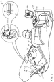
- Fig. 1 is a pictorial illustration of a system 10 for performing ablative procedures on a heart 12 of a living subject, which is constructed and operative in accordance with a disclosed embodiment of the invention.
- the system comprises a catheter 14, which is percutaneously inserted by an operator 16 through the patient's vascular system into a chamber or vascular structure of the heart 12.
- the operator 16 who is typically a physician, brings the catheter's distal tip 18 into contact with the heart wall, for example, at an ablation target site.
- Electrical activation maps may be prepared, according to the methods disclosed in U.S. Patent Nos. 6,226,542 , and 6,301,496 , and in commonly assigned U.S. Patent No.
- Areas determined to be abnormal can be ablated by application of thermal energy, e.g., by passage of radiofrequency electrical current through wires in the catheter to one or more electrodes at the distal tip 18, which apply the radiofrequency energy to the myocardium.
- the energy is absorbed in the tissue, heating it to a point (typically about 50°C) at which it permanently loses its electrical excitability.
- this procedure creates non-conducting lesions in the cardiac tissue, which disrupt the abnormal electrical pathway causing the arrhythmia.
- the principles of the invention can be applied to different heart chambers to diagnose and treat many different cardiac arrhythmias.
- the catheter 14 typically comprises a handle 20, having suitable controls on the handle to enable the operator 16 to steer, position and orient the distal end of the catheter as desired for the ablation.
- the distal portion of the catheter 14 contains position sensors (not shown) that provide signals to a processor 22, located in a console 24.
- the processor 22 may fulfill several processing functions as described below.
- Ablation energy and electrical signals can be conveyed to and from the heart 12 through one or more ablation electrodes 32 located at or near the distal tip 18 via cable 34 to the console 24. Pacing signals and other control signals may be conveyed from the console 24 through the cable 34 and the electrodes 32 to the heart 12. Sensing electrodes 33, also connected to the console 24 are disposed between the ablation electrodes 32 and have connections to the cable 34.
- Wire connections 35 link the console 24 with body surface electrodes 30 and other components of a positioning sub-system for measuring location and orientation coordinates of the catheter 14.
- the processor 22 or another processor may be an element of the positioning subsystem.
- the electrodes 32 and the body surface electrodes 30 may be used to measure tissue impedance at the ablation site as taught in U.S. Patent No. 7,536,218, issued to Govari et al. , which is herein incorporated by reference.
- a temperature sensor (not shown), typically a thermocouple or thermistor, may be mounted on or near each of the electrodes 32.
- the console 24 typically contains one or more ablation power generators 25.
- the catheter 14 may be adapted to conduct ablative energy to the heart using any known ablation technique, e.g., radiofrequency energy, ultrasound energy, and laser-produced light energy. Such methods are disclosed in commonly assigned U.S. Patent Nos. 6,814,733 , 6,997,924 , and 7,156,816 , which are herein incorporated by reference.
- the positioning subsystem comprises a magnetic position tracking arrangement that determines the position and orientation of the catheter 14 by generating magnetic fields in a predefined working volume and sensing these fields at the catheter, using field generating coils 28.
- the positioning subsystem U.S. Patent No. 7,756,576 which is hereby incorporated by reference, and in the above-noted U.S. Patent No. 7,536,218 .
- the catheter 14 is coupled to the console 24, which enables the operator 16 to observe and regulate the functions of the catheter 14.
- Console 24 includes a processor, preferably a computer with appropriate signal processing circuits.
- the processor is coupled to drive a monitor 29.
- the signal processing circuits typically receive, amplify, filter and digitize signals from the catheter 14, including signals generated by the above-noted sensors and a plurality of location sensing electrodes (not shown) located distally in the catheter 14.
- the digitized signals are received and used by the console 24 and the positioning system to compute the position and orientation of the catheter 14 and to analyze the electrical signals from the electrodes.
- the system 10 includes other elements, which are not shown in the figures for the sake of simplicity.
- the system 10 may include an electrocardiogram (ECG) monitor, coupled to receive signals from one or more body surface electrodes, in order to provide an ECG synchronization signal to the console 24.
- ECG electrocardiogram
- the system 10 typically also includes a reference position sensor, either on an externally-applied reference patch attached to the exterior of the subject's body, or on an internally-placed catheter, which is inserted into the heart 12 maintained in a fixed position relative to the heart 12. Conventional pumps and lines for circulating liquids through the catheter 14 for cooling the ablation site are provided.
- the system 10 may receive image data from an external imaging modality, such as an MRI unit or the like and includes image processors that can be incorporated in or invoked by the processor 22 for generating and displaying images that are described below.
- FIG. 2 is an elevation of a multi-electrode catheter 37, in accordance with an embodiment of the invention.
- a framework 39 is deformable and deployable through a shaft 41.
- the framework 39 comprises several closed electrically conducting resilient wire loops 43, typically at least 6 or 7 loops, as shown in Fig. 2 , defining a chamber 45.
- Each of the loops 43 functions independently as a single-axis magnetic location sensor when subjected to the magnetic field produced by field generating coils 28 ( Fig. 1 ).
- the loops 43 are electrically insulated from one another.
- Adjacent loops 43 contact one another and intersect, e.g., at points 47, or be tangent, e.g., at point 49.As the framework 39 deforms, the springiness of the structure keeps the loops 43 in contact, and the points of contact can slide along the frame.
- a larger or smaller number of loops than shown in Fig. 2 may be provided on the framework 39, limited by mechanical requirements of size, flexibility and number of electrodes desired. Three to eight loops are practical.
- the loops 43 in a current embodiment have areas of about 300 mm 2 such that the area bounded by a loop is the same order of magnitude as the area of one of the magnetic sensor coils (number of turns times coil area) in conventional catheters, such as the Navistar ® catheter. Areas as low as 50 mm 2 may be useful.
- the loops 43 experience electromagnetic fields and function as single-axis magnetic sensors. When the loops are subjected to electromagnetic fields at respective frequencies it has been found that the location of each loop can be determined to within 1 mm by combining signals obtained from the loops using the positioning subsystem of the system 10 ( Fig. 1 ). Once the locations of the loops are known, the location of distal end 51 of the catheter can also be determined.
- the loops 43 are formed of wires. Any conducting material can be used. Suitable materials include copper, stainless steel, and nitinol. Materials having shape memory may be advantageous in maintaining contact between the electrodes 53 and the endocardial surface of the heart chamber. The inventors have found in simulations that the average field strength over a large loop is the same as the field at the centroid of the loop.
- the requisite size of the loops relates inversely to the intensity of the magnetic fields produced by field generating coils 28 ( Fig. 1 ). If the field is too weak, then the size of the loops would become impractical as the framework could not be easily accommodated in a cardiac chamber. On the other hand, if the loops were reduced in size, the required magnetic field strength would increase, in which case the field generating coils 28 and generators 25 would become expensive and might require additional protection for the operator and other personnel involved in the procedure.
- Electrodes 53 are typically disposed on the loops 43. While only one electrode is shown on each loop in Fig. 2 , any number of electrodes may be placed on the loops 43 in order to increase contact between the framework 39 and target tissue, and thereby improve the resolution of the electroanatomic map.
- the electrodes 53 are linked to the console 24 ( Fig. 1 ) by separate conductors (not shown).
- Fig. 3 shows a model 55 of the framework 39 ( Fig. 2 ) in accordance with an embodiment of the invention, in which the loops of the framework are here represented as hexagons 57.
- the loops can be approximated by polygons with any number of sides.
- the polygons need not be regular polygons or even identical, so long as their segments approximately conform to the shapes of the loops. Any such polygon can be partitioned into triangles using an interior point as described below.
- the loops are modeled as hexagons with various relative dimensions.
- a useful feature of hexagons is that they can be subdivided into triangles. That means even when the hexagon is deformed, and its border is no longer planar, the theoretical magnetic flux can be modeled as the sum of theoretical magnetic fluxes over the triangular segments, which are, by definition, planar.
- Fig. 3 models a catheter whose framework comprises six hexagons 57. As shown at the right of the figure, Each hexagon 57 contains six triangles 61, 63, 65, 67, 69, 71, which have a common vertex 73.
- Fig. 4 is a representation of the triangles 71 ( Fig. 3 ), in accordance with an embodiment of the invention.
- the coordinates of each triangle can be defined in its own local coordinate system, Tri ij local , where each Tr i is a list of three points. Giving each vertex a label (1, 2, 3), the x-axis is the line connecting points 1 and 2. The origin is the midpoint.
- Rot ij loc ⁇ CARTO and T ij loc ⁇ CARTO where Rot refers to a 3 ⁇ 3 rotation matrix and T to a translation vector.
- the index i runs from 1 to 6 and refers to a particular hexagon, and the index j refers to a triangle within the hexagon.
- Tri ij CARTO Rot ij loc ⁇ CARTO • Tri ij local + T ij loc ⁇ CARTO .
- Tri i , 1 2 3 4 5,6 CARTO 3 Tri i , 2 3 4 5 6,1 CARTO 2
- Fig. 5 is a diagram similar to Fig. 3 that illustrates the intersection of faces of model 55 in accordance with an embodiment of the invention. Indices of the hexagons and triangles are shown.
- Segment 79 (defined by points (3,2), (3,3)) of hexagon 81 on the right intersects segment 83 (defined by points (2,2), (2,3)) of hexagon 82.
- segment 86 (defined by points (5.2), (5,3)) of hexagon 81 intersects segment 84 (defined by points (6,2),(6,3)) of hexagon 82.
- the vectors x 1 and x 2 are endpoints of one segment, and the vectors x 3 and x 4 are endpoints of the other. This involves the addition of no 1 new parameters.
- each of the terms x i is expressed in terms of the local triangles and the transformations to the CARTO coordinate system.
- the value locMeas i is determined, mutatis mutandis, by the method, disclosed in detail in commonly assigned U.S. Patent No 8,818,486 , Briefly, the method involves generating a magnetic field in a predefined volume.
- a reference model is defined, which models the magnetic field at multiple points in the volume using spherical harmonics.
- the magnetic field is measured by a field detector, which is coupled to an intra-body probe inserted into an organ of a living body located in the volume.
- a second cost function is defined by comparing the measured magnetic field with the reference magnetic field model within the volume. The cost function is minimized by a computation over dipole terms in a derivative over the cost function so as to find a position and orientation that matches the measured magnetic field.
- the found position and orientation is outputted as the position and orientation of a probe in the organ.
- the location of the first point in triangle 1 of each hexagon matches the location found by using the measured signal from the hexagon.
- B CARTO ( x,y,z ) is the estimated field value at a location using a mathematical model such as described in the above-noted U.S. Patent No 8,818,486 . That implies that the value Signal i is also a model based value.
- the estimated flux in each hexagon matches the measured flux.
- Adjacent hexagons meet at a point.
- the following equations show the meeting of triangle 3 from one hexagon with triangle 4 of the adjacent hexagon, e.g., segments 79, 83.
- cost full w 1 cost centroid + w 2 cost Flux _ Hex + w 3 cost vertex 1 + w 4 cost triangles + w 5 cost cross _ top + w 6 cost cross _ bottom
- variables w1 - w6 are relative weighting terms. In the results presented here they are all set to 1.
- the parameters are found by minimizing the above cost function.
- the optimization is begun with the entire structure displaced and deformed by bending at some of the hexagon joints.
- the reconstruction accuracy was at the sub-millimeter level.
- Fig. 6 is a flow chart summarizing the procedure for determining the catheter location in accordance with an embodiment of the invention.
- a catheter framework is modeled as a series of hexagons subdivided into triangles.
- step 87 local coordinates of each triangle are defined.
- step 89 the local coordinates of the triangles are transformed into CARTO coordinates.
- the initial parameters of the transform can be a priori values or can be obtained from a previous solution as shown in step 90.
- step 101 theoretical fluxes and signals for the triangles and hexagons are obtained as described above.
- Step 103 applies measured signals to the solution in step 103 for the parameters of the transformations of each triangle to the CARTO coordinate system by optimizing the cost function described above -- applying Equation 4 and Equation 5 to the triangles using their areas and centroids (in CARTO coordinates) to compute the flux in each of the hexagons and then to compute the signal obtained from each of the hexagons.
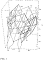
- Fig. 7 is an exemplary reconstruction of a catheter framework similar to the framework 39 ( Fig. 2 ) using data obtained using a robot, in accordance with an embodiment of the invention and complying with the above-noted conditions.
- the figure shows an exemplary robot position.
- the procedure described with respect to Fig. 6 may be used to compute the signals obtained from hexagons 93. More generally, the procedure of Fig. 6 is applicable to models of frameworks containing any number of loops.
- Reconstructed hexagons 93 are shown in solid lines and hexagons 95 in broken lines.
- the hexagons 95 represent actual positions of the loops based on knowledge of the robot location and engineered geometry of the catheter
- Fig. 8 is a bar chart showing the result of the fit.
- the chart shows the distribution of errors in the locations of each point on the triangles. This result is for one of 27 robot locations. The other locations give similar results.
- Fig. 9 illustrates a simulated fit in which the hexagons were allowed to deform in accordance with an embodiment of the invention.
- the vertex location errors tend to be larger than those shown in Fig. 8 .
- a wire framework is not limited to the embodiment shown in Fig. 2 .
- the principles of the invention can be applied to other frame shapes and arrangement.
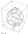
- Reference is now made to Fig. 10 which shows a wire framework 97 deployable through a catheter 99, in accordance with an alternate embodiment of the invention.
- Individual wires spiral about an axis, contact one another and form closed loops as in Fig. 2 .
- the pitch of the spirals may be identical, but are not necessarily so.
- Other constructions will occur to those skilled in the art and may be applied as described above.
Landscapes
- Health & Medical Sciences (AREA)
- Life Sciences & Earth Sciences (AREA)
- Engineering & Computer Science (AREA)
- Surgery (AREA)
- Heart & Thoracic Surgery (AREA)
- Animal Behavior & Ethology (AREA)
- Biomedical Technology (AREA)
- General Health & Medical Sciences (AREA)
- Public Health (AREA)
- Veterinary Medicine (AREA)
- Medical Informatics (AREA)
- Molecular Biology (AREA)
- Physics & Mathematics (AREA)
- Biophysics (AREA)
- Pathology (AREA)
- Cardiology (AREA)
- Nuclear Medicine, Radiotherapy & Molecular Imaging (AREA)
- Plasma & Fusion (AREA)
- Otolaryngology (AREA)
- Human Computer Interaction (AREA)
- Radiology & Medical Imaging (AREA)
- Physiology (AREA)
- Vascular Medicine (AREA)
- Media Introduction/Drainage Providing Device (AREA)
- Measurement And Recording Of Electrical Phenomena And Electrical Characteristics Of The Living Body (AREA)
- Measurement Of Length, Angles, Or The Like Using Electric Or Magnetic Means (AREA)
Claims (13)
- Computerimplementiertes Verfahren, das Folgendes umfasst:Modellieren mehrerer elektrisch leitender Drahtschlaufen einer Sonde als jeweilige Polygone, wobei die Sonde ein distales Ende mit einem Rahmen, der an dem distalen Ende angeordnet ist, aufweist, wobei der Rahmen die Drahtschlaufen umfasst, die eine Kammer definieren, wobei die Drahtschlaufen unabhängig mit einem Empfänger verbunden sind;Unterteilen der Polygone in mehrere Dreiecke;Beaufschlagen der Drahtschlaufen mit magnetischen Flüssen mit jeweiligen Frequenzen;Lesen der Signale von den Drahtschlaufen in Reaktion auf die magnetischen Flüsse mit den jeweiligen Frequenzen;Berechnen der theoretischen magnetischen Flüsse in den Polygonen als jeweilige Summen der theoretischen magnetischen Flüsse in deren Dreiecken; undBestimmen eines Ortes und einer Orientierung des Rahmens, indem die berechneten theoretischen magnetischen Flüsse mit den Signalen in Beziehung gesetzt werden.
- Verfahren nach Anspruch 1, wobei die Polygone Sechsecke sind.
- Verfahren nach Anspruch 1, wobei das Unterteilen der Polygone in mehrere Dreiecke die folgenden Schritte umfasst:Identifizieren der lokalen Koordinaten der Dreiecke in einem lokalen Koordinatensystem; undTransformieren der lokalen Koordinaten der Dreiecke in Koordinaten eines magnetischen Positionsverfolgungssystems.
- Verfahren nach Anspruch 3, wobei das Transformieren der lokalen Koordinaten durch das Optimieren einer Kostenfunktion ausgeführt wird.
- Verfahren nach Anspruch 1, wobei das Berechnen der theoretischen magnetischen Flüsse auf den Flächen und den Schwerpunkten der Dreiecke basiert.
- Verfahren nach Anspruch 1, wobei das Modellieren der Drahtschlaufen ferner das Anwenden einer ersten Einschränkung umfasst, wobei sich die Segmente der Dreiecke benachbarter Polygone schneiden müssen.
- Verfahren nach Anspruch 1, wobei das Modellieren der Drahtschlaufen ferner das Anwenden einer zweiten Einschränkung umfasst, wobei eine Spitze jedes Dreiecks eines Polygons mit einer Spitze eines benachbarten Dreiecks des einen Polygons übereinstimmt.
- Verfahren nach Anspruch 1, wobei das Modellieren der Drahtschlaufen ferner das Anwenden einer dritten Einschränkung umfasst, wobei benachbarte Polygone einander an exakt zwei Punkten kontaktieren.
- Verfahren nach Anspruch 1, wobei die Schlaufen drei bis acht Schlaufen umfassen.
- Verfahren nach Anspruch 1, wobei die Schlaufen sechs bis sieben Schlaufen umfassen.
- Verfahren nach Anspruch 1, wobei die Schlaufen Spiralen um eine Achse bilden.
- Verfahren nach Anspruch 1, wobei die Schlaufen deformierbar sind, das ferner das Ausbringen des Rahmens durch ein Lumen der Sonde umfasst.
- Verfahren nach Anspruch 1, wobei eine der Schlaufen wenigstens eine weitere der Schlaufen kontaktiert.
Priority Applications (2)
| Application Number | Priority Date | Filing Date | Title |
|---|---|---|---|
| EP22197995.8A EP4169442B1 (de) | 2015-12-23 | 2016-12-22 | Katheterrahmenteile als grosse einachsige sensoren |
| EP26165523.7A EP4736796A3 (de) | 2015-12-23 | 2016-12-22 | Katheterrahmenteile als grosse einachsige sensoren |
Applications Claiming Priority (2)
| Application Number | Priority Date | Filing Date | Title |
|---|---|---|---|
| US14/757,678 US10687761B2 (en) | 2015-12-23 | 2015-12-23 | Catheter frame pieces used as large single axis sensors |
| EP16206174.1A EP3184037B8 (de) | 2015-12-23 | 2016-12-22 | Katheterrahmenteile als grosse einzelachsensensoren |
Related Parent Applications (2)
| Application Number | Title | Priority Date | Filing Date |
|---|---|---|---|
| EP16206174.1A Division EP3184037B8 (de) | 2015-12-23 | 2016-12-22 | Katheterrahmenteile als grosse einzelachsensensoren |
| EP16206174.1A Division-Into EP3184037B8 (de) | 2015-12-23 | 2016-12-22 | Katheterrahmenteile als grosse einzelachsensensoren |
Related Child Applications (2)
| Application Number | Title | Priority Date | Filing Date |
|---|---|---|---|
| EP22197995.8A Division EP4169442B1 (de) | 2015-12-23 | 2016-12-22 | Katheterrahmenteile als grosse einachsige sensoren |
| EP26165523.7A Division EP4736796A3 (de) | 2015-12-23 | 2016-12-22 | Katheterrahmenteile als grosse einachsige sensoren |
Publications (2)
| Publication Number | Publication Date |
|---|---|
| EP3936033A1 EP3936033A1 (de) | 2022-01-12 |
| EP3936033B1 true EP3936033B1 (de) | 2022-09-28 |
Family
ID=57714431
Family Applications (4)
| Application Number | Title | Priority Date | Filing Date |
|---|---|---|---|
| EP21192763.7A Active EP3936033B1 (de) | 2015-12-23 | 2016-12-22 | Katheterrahmenteile als grosse einzelachsensensoren |
| EP16206174.1A Active EP3184037B8 (de) | 2015-12-23 | 2016-12-22 | Katheterrahmenteile als grosse einzelachsensensoren |
| EP22197995.8A Active EP4169442B1 (de) | 2015-12-23 | 2016-12-22 | Katheterrahmenteile als grosse einachsige sensoren |
| EP26165523.7A Pending EP4736796A3 (de) | 2015-12-23 | 2016-12-22 | Katheterrahmenteile als grosse einachsige sensoren |
Family Applications After (3)
| Application Number | Title | Priority Date | Filing Date |
|---|---|---|---|
| EP16206174.1A Active EP3184037B8 (de) | 2015-12-23 | 2016-12-22 | Katheterrahmenteile als grosse einzelachsensensoren |
| EP22197995.8A Active EP4169442B1 (de) | 2015-12-23 | 2016-12-22 | Katheterrahmenteile als grosse einachsige sensoren |
| EP26165523.7A Pending EP4736796A3 (de) | 2015-12-23 | 2016-12-22 | Katheterrahmenteile als grosse einachsige sensoren |
Country Status (7)
| Country | Link |
|---|---|
| US (4) | US10687761B2 (de) |
| EP (4) | EP3936033B1 (de) |
| JP (2) | JP7051291B2 (de) |
| CN (1) | CN106963478B (de) |
| AU (1) | AU2016259379A1 (de) |
| CA (1) | CA2950924A1 (de) |
| IL (1) | IL249200B (de) |
Families Citing this family (17)
| Publication number | Priority date | Publication date | Assignee | Title |
|---|---|---|---|---|
| US10687761B2 (en) | 2015-12-23 | 2020-06-23 | Biosense Webster (Israel) Ltd. | Catheter frame pieces used as large single axis sensors |
| US11058496B2 (en) * | 2016-08-15 | 2021-07-13 | Biosense Webster (Israel) Ltd. | Registering probe and sheath images on a display |
| US12029545B2 (en) * | 2017-05-30 | 2024-07-09 | Biosense Webster (Israel) Ltd. | Catheter splines as location sensors |
| US10575746B2 (en) * | 2017-12-14 | 2020-03-03 | Biosense Webster (Israel) Ltd. | Epicardial mapping |
| US12588952B2 (en) | 2019-01-25 | 2026-03-31 | Biosense Webster (Israel) Ltd. | Flexible multi-coil tracking sensor |
| US11850051B2 (en) * | 2019-04-30 | 2023-12-26 | Biosense Webster (Israel) Ltd. | Mapping grid with high density electrode array |
| US11759150B2 (en) | 2019-08-27 | 2023-09-19 | Biosense Webster (Israel) Ltd. | Accurate basket catheter tracking |
| US20210369132A1 (en) | 2020-05-29 | 2021-12-02 | Biosense Webster (Israel) Ltd. | Intraluminal reference electrode for cardiovascular treatment apparatus |
| CN112294428B (zh) * | 2020-09-17 | 2022-05-13 | 杭州堃博生物科技有限公司 | 用于实施肺部神经消融的射频消融导管 |
| US11484369B2 (en) * | 2020-10-28 | 2022-11-01 | Biosense Webster (Israel) Ltd. | Identifying instances of cardioversion while building a position map |
| US20220175295A1 (en) * | 2020-12-08 | 2022-06-09 | Biosense Webster (Israel) Ltd. | Signal processing of velocity streams of a signal flow for coherent mapping of an anatomical structure |
| US20240065755A1 (en) | 2022-08-23 | 2024-02-29 | Biosense Webster (Israel) Ltd. | Planar multi-electrode catheters |
| US20240066289A1 (en) * | 2022-08-26 | 2024-02-29 | Covidien Lp | Endovascular deep brain stimulation |
| US20250000574A1 (en) * | 2023-06-29 | 2025-01-02 | Biosense Webster (Israel) Ltd. | System and method for shape tracking of intrabody object subject to deformation |
| USD1090847S1 (en) | 2023-08-07 | 2025-08-26 | Biosense Webster (Israel) Ltd. | Distal portion of catheter |
| US20250082383A1 (en) | 2023-09-08 | 2025-03-13 | Biosense Webster (Israel) Ltd. | Medical device with tactile feedback for spine deployment |
| US20250082396A1 (en) | 2023-09-08 | 2025-03-13 | Biosense Webster (Israel) Ltd. | Expandable electrode assembly comprising extended distal end for a medical catheter |
Family Cites Families (33)
| Publication number | Priority date | Publication date | Assignee | Title |
|---|---|---|---|---|
| US5772590A (en) | 1992-06-30 | 1998-06-30 | Cordis Webster, Inc. | Cardiovascular catheter with laterally stable basket-shaped electrode array with puller wire |
| US5636634A (en) * | 1993-03-16 | 1997-06-10 | Ep Technologies, Inc. | Systems using guide sheaths for introducing, deploying, and stabilizing cardiac mapping and ablation probes |
| US5391199A (en) | 1993-07-20 | 1995-02-21 | Biosense, Inc. | Apparatus and method for treating cardiac arrhythmias |
| IL116699A (en) | 1996-01-08 | 2001-09-13 | Biosense Ltd | Method of building a heart map |
| US5558091A (en) | 1993-10-06 | 1996-09-24 | Biosense, Inc. | Magnetic determination of position and orientation |
| EP0910278B1 (de) * | 1996-02-15 | 2005-11-23 | Biosense Webster, Inc. | Mit einer öffnung versehener katheter |
| DE69732362T2 (de) | 1996-02-15 | 2006-03-23 | Biosense Webster, Inc., Diamond Bar | Methode zur Eichung einer Sonde |
| AU722748B2 (en) | 1996-05-06 | 2000-08-10 | Biosense, Inc. | Radiator calibration |
| DE69728142T2 (de) | 1997-01-03 | 2005-01-20 | Biosense, Inc., Miami | Katheter mit anpassbarer form |
| EP0973454B1 (de) | 1998-02-10 | 2007-01-17 | Biosense Webster, Inc. | Sondenanordnung zur verbesserten katheterkalibrierung |
| US6301496B1 (en) | 1998-07-24 | 2001-10-09 | Biosense, Inc. | Vector mapping of three-dimensionally reconstructed intrabody organs and method of display |
| US6226542B1 (en) | 1998-07-24 | 2001-05-01 | Biosense, Inc. | Three-dimensional reconstruction of intrabody organs |
| US6892091B1 (en) | 2000-02-18 | 2005-05-10 | Biosense, Inc. | Catheter, method and apparatus for generating an electrical map of a chamber of the heart |
| US6814733B2 (en) | 2002-01-31 | 2004-11-09 | Biosense, Inc. | Radio frequency pulmonary vein isolation |
| US6997924B2 (en) | 2002-09-17 | 2006-02-14 | Biosense Inc. | Laser pulmonary vein isolation |
| US7156816B2 (en) | 2002-11-26 | 2007-01-02 | Biosense, Inc. | Ultrasound pulmonary vein isolation |
| US7366557B2 (en) | 2003-11-07 | 2008-04-29 | Biosense Webster, Inc. | Flower catheter |
| US7536218B2 (en) | 2005-07-15 | 2009-05-19 | Biosense Webster, Inc. | Hybrid magnetic-based and impedance-based position sensing |
| US7756576B2 (en) | 2005-08-26 | 2010-07-13 | Biosense Webster, Inc. | Position sensing and detection of skin impedance |
| US20070161888A1 (en) * | 2005-12-30 | 2007-07-12 | Sherman Jason T | System and method for registering a bone of a patient with a computer assisted orthopaedic surgery system |
| US20080139915A1 (en) | 2006-12-07 | 2008-06-12 | Medtronic Vascular, Inc. | Vascular Position Locating and/or Mapping Apparatus and Methods |
| CA2799336A1 (en) * | 2010-05-12 | 2011-11-17 | Medical Device Innovations Inc. | Method and device for treatment of arrhythmias and other maladies |
| US10492868B2 (en) * | 2011-01-28 | 2019-12-03 | Medtronic Navigation, Inc. | Method and apparatus for image-based navigation |
| US9162036B2 (en) * | 2011-12-30 | 2015-10-20 | Biosense Webster (Israel), Ltd. | Medical device control handle with multiple puller wires |
| US9717555B2 (en) * | 2012-05-14 | 2017-08-01 | Biosense Webster (Israel), Ltd. | Catheter with helical end section for vessel ablation |
| US8818486B2 (en) * | 2012-07-12 | 2014-08-26 | Biosense Webster (Israel) Ltd. | Position and orientation algorithm for a single axis sensor |
| US10105073B2 (en) | 2013-11-21 | 2018-10-23 | Biosense Webster (Israel) Ltd | Flexible multiple-arm diagnostic catheter |
| US20150196216A1 (en) * | 2014-01-13 | 2015-07-16 | Boston Scientific Scimed, Inc. | Medical devices for mapping cardiac tissue |
| US9795315B2 (en) * | 2014-01-28 | 2017-10-24 | John Bullinga | Catheter system for mapping of the left atrium, right atrium and coronary sinus |
| US10136829B2 (en) * | 2014-02-25 | 2018-11-27 | St. Jude Medical, Cardiology Division, Inc. | Systems and methods for using electrophysiology properties for classifying arrhythmia sources |
| CN106413539A (zh) * | 2014-06-04 | 2017-02-15 | 波士顿科学医学有限公司 | 电极组件 |
| US10610112B2 (en) * | 2015-02-19 | 2020-04-07 | Auckland Uniservices Limited | Heart mapping system |
| US10687761B2 (en) | 2015-12-23 | 2020-06-23 | Biosense Webster (Israel) Ltd. | Catheter frame pieces used as large single axis sensors |
-
2015
- 2015-12-23 US US14/757,678 patent/US10687761B2/en active Active
-
2016
- 2016-11-17 AU AU2016259379A patent/AU2016259379A1/en not_active Abandoned
- 2016-11-24 IL IL249200A patent/IL249200B/en active IP Right Grant
- 2016-12-07 CA CA2950924A patent/CA2950924A1/en not_active Abandoned
- 2016-12-22 JP JP2016248944A patent/JP7051291B2/ja active Active
- 2016-12-22 EP EP21192763.7A patent/EP3936033B1/de active Active
- 2016-12-22 EP EP16206174.1A patent/EP3184037B8/de active Active
- 2016-12-22 EP EP22197995.8A patent/EP4169442B1/de active Active
- 2016-12-22 EP EP26165523.7A patent/EP4736796A3/de active Pending
- 2016-12-23 CN CN201611206260.XA patent/CN106963478B/zh active Active
-
2020
- 2020-06-02 US US16/890,964 patent/US11647958B2/en active Active
-
2022
- 2022-03-30 JP JP2022055581A patent/JP7282946B2/ja active Active
-
2023
- 2023-04-07 US US18/297,404 patent/US12220260B2/en active Active
-
2025
- 2025-01-17 US US19/027,349 patent/US20250160752A1/en active Pending
Also Published As
| Publication number | Publication date |
|---|---|
| IL249200A0 (en) | 2017-01-31 |
| EP4169442B1 (de) | 2026-03-18 |
| CN106963478A (zh) | 2017-07-21 |
| JP7282946B2 (ja) | 2023-05-29 |
| EP3936033A1 (de) | 2022-01-12 |
| EP3184037A1 (de) | 2017-06-28 |
| JP2017113566A (ja) | 2017-06-29 |
| US20200289059A1 (en) | 2020-09-17 |
| US20170181706A1 (en) | 2017-06-29 |
| EP4736796A2 (de) | 2026-05-06 |
| CA2950924A1 (en) | 2017-06-23 |
| EP3184037B1 (de) | 2021-08-25 |
| IL249200B (en) | 2021-04-29 |
| EP4169442C0 (de) | 2026-03-18 |
| US20250160752A1 (en) | 2025-05-22 |
| JP2022091913A (ja) | 2022-06-21 |
| EP3184037B8 (de) | 2021-12-01 |
| US10687761B2 (en) | 2020-06-23 |
| AU2016259379A1 (en) | 2017-07-13 |
| JP7051291B2 (ja) | 2022-04-11 |
| US11647958B2 (en) | 2023-05-16 |
| US20230248315A1 (en) | 2023-08-10 |
| EP4169442A1 (de) | 2023-04-26 |
| CN106963478B (zh) | 2022-01-25 |
| EP4736796A3 (de) | 2026-07-08 |
| US12220260B2 (en) | 2025-02-11 |
Similar Documents
| Publication | Publication Date | Title |
|---|---|---|
| US12220260B2 (en) | Catheter frame pieces used as large single axis sensors | |
| AU2020200911B2 (en) | Registration maps using intra-cardiac signals | |
| EP3453328B1 (de) | Algorithmus zur mesh-einpassung | |
| US11109788B2 (en) | Catheter with Fibonacci distributed electrodes | |
| US11382530B2 (en) | Symmetric short contact force sensor with four coils | |
| EP4122413A1 (de) | Genaue gewebenähe |
Legal Events
| Date | Code | Title | Description |
|---|---|---|---|
| PUAI | Public reference made under article 153(3) epc to a published international application that has entered the european phase |
Free format text: ORIGINAL CODE: 0009012 |
|
| STAA | Information on the status of an ep patent application or granted ep patent |
Free format text: STATUS: THE APPLICATION HAS BEEN PUBLISHED |
|
| AC | Divisional application: reference to earlier application |
Ref document number: 3184037 Country of ref document: EP Kind code of ref document: P |
|
| AK | Designated contracting states |
Kind code of ref document: A1 Designated state(s): AL AT BE BG CH CY CZ DE DK EE ES FI FR GB GR HR HU IE IS IT LI LT LU LV MC MK MT NL NO PL PT RO RS SE SI SK SM TR |
|
| B565 | Issuance of search results under rule 164(2) epc |
Effective date: 20211210 |
|
| STAA | Information on the status of an ep patent application or granted ep patent |
Free format text: STATUS: REQUEST FOR EXAMINATION WAS MADE |
|
| 17P | Request for examination filed |
Effective date: 20220125 |
|
| RBV | Designated contracting states (corrected) |
Designated state(s): AL AT BE BG CH CY CZ DE DK EE ES FI FR GB GR HR HU IE IS IT LI LT LU LV MC MK MT NL NO PL PT RO RS SE SI SK SM TR |
|
| GRAP | Despatch of communication of intention to grant a patent |
Free format text: ORIGINAL CODE: EPIDOSNIGR1 |
|
| STAA | Information on the status of an ep patent application or granted ep patent |
Free format text: STATUS: GRANT OF PATENT IS INTENDED |
|
| INTG | Intention to grant announced |
Effective date: 20220614 |
|
| GRAS | Grant fee paid |
Free format text: ORIGINAL CODE: EPIDOSNIGR3 |
|
| GRAA | (expected) grant |
Free format text: ORIGINAL CODE: 0009210 |
|
| STAA | Information on the status of an ep patent application or granted ep patent |
Free format text: STATUS: THE PATENT HAS BEEN GRANTED |
|
| AC | Divisional application: reference to earlier application |
Ref document number: 3184037 Country of ref document: EP Kind code of ref document: P |
|
| AK | Designated contracting states |
Kind code of ref document: B1 Designated state(s): AL AT BE BG CH CY CZ DE DK EE ES FI FR GB GR HR HU IE IS IT LI LT LU LV MC MK MT NL NO PL PT RO RS SE SI SK SM TR |
|
| REG | Reference to a national code |
Ref country code: GB Ref legal event code: FG4D |
|
| REG | Reference to a national code |
Ref country code: CH Ref legal event code: EP |
|
| REG | Reference to a national code |
Ref country code: AT Ref legal event code: REF Ref document number: 1520703 Country of ref document: AT Kind code of ref document: T Effective date: 20221015 |
|
| REG | Reference to a national code |
Ref country code: DE Ref legal event code: R096 Ref document number: 602016075396 Country of ref document: DE |
|
| REG | Reference to a national code |
Ref country code: IE Ref legal event code: FG4D |
|
| REG | Reference to a national code |
Ref country code: NL Ref legal event code: FP |
|
| REG | Reference to a national code |
Ref country code: LT Ref legal event code: MG9D |
|
| PG25 | Lapsed in a contracting state [announced via postgrant information from national office to epo] |
Ref country code: SE Free format text: LAPSE BECAUSE OF FAILURE TO SUBMIT A TRANSLATION OF THE DESCRIPTION OR TO PAY THE FEE WITHIN THE PRESCRIBED TIME-LIMIT Effective date: 20220928 Ref country code: RS Free format text: LAPSE BECAUSE OF FAILURE TO SUBMIT A TRANSLATION OF THE DESCRIPTION OR TO PAY THE FEE WITHIN THE PRESCRIBED TIME-LIMIT Effective date: 20220928 Ref country code: NO Free format text: LAPSE BECAUSE OF FAILURE TO SUBMIT A TRANSLATION OF THE DESCRIPTION OR TO PAY THE FEE WITHIN THE PRESCRIBED TIME-LIMIT Effective date: 20221228 Ref country code: LV Free format text: LAPSE BECAUSE OF FAILURE TO SUBMIT A TRANSLATION OF THE DESCRIPTION OR TO PAY THE FEE WITHIN THE PRESCRIBED TIME-LIMIT Effective date: 20220928 Ref country code: LT Free format text: LAPSE BECAUSE OF FAILURE TO SUBMIT A TRANSLATION OF THE DESCRIPTION OR TO PAY THE FEE WITHIN THE PRESCRIBED TIME-LIMIT Effective date: 20220928 Ref country code: FI Free format text: LAPSE BECAUSE OF FAILURE TO SUBMIT A TRANSLATION OF THE DESCRIPTION OR TO PAY THE FEE WITHIN THE PRESCRIBED TIME-LIMIT Effective date: 20220928 |
|
| PGFP | Annual fee paid to national office [announced via postgrant information from national office to epo] |
Ref country code: NL Payment date: 20221114 Year of fee payment: 7 |
|
| REG | Reference to a national code |
Ref country code: AT Ref legal event code: MK05 Ref document number: 1520703 Country of ref document: AT Kind code of ref document: T Effective date: 20220928 |
|
| PG25 | Lapsed in a contracting state [announced via postgrant information from national office to epo] |
Ref country code: HR Free format text: LAPSE BECAUSE OF FAILURE TO SUBMIT A TRANSLATION OF THE DESCRIPTION OR TO PAY THE FEE WITHIN THE PRESCRIBED TIME-LIMIT Effective date: 20220928 Ref country code: GR Free format text: LAPSE BECAUSE OF FAILURE TO SUBMIT A TRANSLATION OF THE DESCRIPTION OR TO PAY THE FEE WITHIN THE PRESCRIBED TIME-LIMIT Effective date: 20221229 |
|
| PG25 | Lapsed in a contracting state [announced via postgrant information from national office to epo] |
Ref country code: SM Free format text: LAPSE BECAUSE OF FAILURE TO SUBMIT A TRANSLATION OF THE DESCRIPTION OR TO PAY THE FEE WITHIN THE PRESCRIBED TIME-LIMIT Effective date: 20220928 Ref country code: RO Free format text: LAPSE BECAUSE OF FAILURE TO SUBMIT A TRANSLATION OF THE DESCRIPTION OR TO PAY THE FEE WITHIN THE PRESCRIBED TIME-LIMIT Effective date: 20220928 Ref country code: PT Free format text: LAPSE BECAUSE OF FAILURE TO SUBMIT A TRANSLATION OF THE DESCRIPTION OR TO PAY THE FEE WITHIN THE PRESCRIBED TIME-LIMIT Effective date: 20230130 Ref country code: ES Free format text: LAPSE BECAUSE OF FAILURE TO SUBMIT A TRANSLATION OF THE DESCRIPTION OR TO PAY THE FEE WITHIN THE PRESCRIBED TIME-LIMIT Effective date: 20220928 Ref country code: CZ Free format text: LAPSE BECAUSE OF FAILURE TO SUBMIT A TRANSLATION OF THE DESCRIPTION OR TO PAY THE FEE WITHIN THE PRESCRIBED TIME-LIMIT Effective date: 20220928 Ref country code: AT Free format text: LAPSE BECAUSE OF FAILURE TO SUBMIT A TRANSLATION OF THE DESCRIPTION OR TO PAY THE FEE WITHIN THE PRESCRIBED TIME-LIMIT Effective date: 20220928 |
|
| PG25 | Lapsed in a contracting state [announced via postgrant information from national office to epo] |
Ref country code: SK Free format text: LAPSE BECAUSE OF FAILURE TO SUBMIT A TRANSLATION OF THE DESCRIPTION OR TO PAY THE FEE WITHIN THE PRESCRIBED TIME-LIMIT Effective date: 20220928 Ref country code: PL Free format text: LAPSE BECAUSE OF FAILURE TO SUBMIT A TRANSLATION OF THE DESCRIPTION OR TO PAY THE FEE WITHIN THE PRESCRIBED TIME-LIMIT Effective date: 20220928 Ref country code: IS Free format text: LAPSE BECAUSE OF FAILURE TO SUBMIT A TRANSLATION OF THE DESCRIPTION OR TO PAY THE FEE WITHIN THE PRESCRIBED TIME-LIMIT Effective date: 20230128 Ref country code: EE Free format text: LAPSE BECAUSE OF FAILURE TO SUBMIT A TRANSLATION OF THE DESCRIPTION OR TO PAY THE FEE WITHIN THE PRESCRIBED TIME-LIMIT Effective date: 20220928 |
|
| REG | Reference to a national code |
Ref country code: DE Ref legal event code: R097 Ref document number: 602016075396 Country of ref document: DE |
|
| PG25 | Lapsed in a contracting state [announced via postgrant information from national office to epo] |
Ref country code: AL Free format text: LAPSE BECAUSE OF FAILURE TO SUBMIT A TRANSLATION OF THE DESCRIPTION OR TO PAY THE FEE WITHIN THE PRESCRIBED TIME-LIMIT Effective date: 20220928 |
|
| PG25 | Lapsed in a contracting state [announced via postgrant information from national office to epo] |
Ref country code: DK Free format text: LAPSE BECAUSE OF FAILURE TO SUBMIT A TRANSLATION OF THE DESCRIPTION OR TO PAY THE FEE WITHIN THE PRESCRIBED TIME-LIMIT Effective date: 20220928 |
|
| REG | Reference to a national code |
Ref country code: CH Ref legal event code: PL |
|
| PLBE | No opposition filed within time limit |
Free format text: ORIGINAL CODE: 0009261 |
|
| STAA | Information on the status of an ep patent application or granted ep patent |
Free format text: STATUS: NO OPPOSITION FILED WITHIN TIME LIMIT |
|
| REG | Reference to a national code |
Ref country code: BE Ref legal event code: MM Effective date: 20221231 |
|
| PG25 | Lapsed in a contracting state [announced via postgrant information from national office to epo] |
Ref country code: LU Free format text: LAPSE BECAUSE OF NON-PAYMENT OF DUE FEES Effective date: 20221222 |
|
| 26N | No opposition filed |
Effective date: 20230629 |
|
| PG25 | Lapsed in a contracting state [announced via postgrant information from national office to epo] |
Ref country code: LI Free format text: LAPSE BECAUSE OF NON-PAYMENT OF DUE FEES Effective date: 20221231 Ref country code: IE Free format text: LAPSE BECAUSE OF NON-PAYMENT OF DUE FEES Effective date: 20221222 Ref country code: CH Free format text: LAPSE BECAUSE OF NON-PAYMENT OF DUE FEES Effective date: 20221231 |
|
| PG25 | Lapsed in a contracting state [announced via postgrant information from national office to epo] |
Ref country code: SI Free format text: LAPSE BECAUSE OF FAILURE TO SUBMIT A TRANSLATION OF THE DESCRIPTION OR TO PAY THE FEE WITHIN THE PRESCRIBED TIME-LIMIT Effective date: 20220928 Ref country code: BE Free format text: LAPSE BECAUSE OF NON-PAYMENT OF DUE FEES Effective date: 20221231 |
|
| PG25 | Lapsed in a contracting state [announced via postgrant information from national office to epo] |
Ref country code: CY Free format text: LAPSE BECAUSE OF FAILURE TO SUBMIT A TRANSLATION OF THE DESCRIPTION OR TO PAY THE FEE WITHIN THE PRESCRIBED TIME-LIMIT Effective date: 20220928 |
|
| PG25 | Lapsed in a contracting state [announced via postgrant information from national office to epo] |
Ref country code: MK Free format text: LAPSE BECAUSE OF FAILURE TO SUBMIT A TRANSLATION OF THE DESCRIPTION OR TO PAY THE FEE WITHIN THE PRESCRIBED TIME-LIMIT Effective date: 20220928 Ref country code: HU Free format text: LAPSE BECAUSE OF FAILURE TO SUBMIT A TRANSLATION OF THE DESCRIPTION OR TO PAY THE FEE WITHIN THE PRESCRIBED TIME-LIMIT; INVALID AB INITIO Effective date: 20161222 |
|
| PG25 | Lapsed in a contracting state [announced via postgrant information from national office to epo] |
Ref country code: MC Free format text: LAPSE BECAUSE OF FAILURE TO SUBMIT A TRANSLATION OF THE DESCRIPTION OR TO PAY THE FEE WITHIN THE PRESCRIBED TIME-LIMIT Effective date: 20220928 |
|
| PG25 | Lapsed in a contracting state [announced via postgrant information from national office to epo] |
Ref country code: TR Free format text: LAPSE BECAUSE OF FAILURE TO SUBMIT A TRANSLATION OF THE DESCRIPTION OR TO PAY THE FEE WITHIN THE PRESCRIBED TIME-LIMIT Effective date: 20220928 Ref country code: MC Free format text: LAPSE BECAUSE OF FAILURE TO SUBMIT A TRANSLATION OF THE DESCRIPTION OR TO PAY THE FEE WITHIN THE PRESCRIBED TIME-LIMIT Effective date: 20220928 |
|
| PG25 | Lapsed in a contracting state [announced via postgrant information from national office to epo] |
Ref country code: BG Free format text: LAPSE BECAUSE OF FAILURE TO SUBMIT A TRANSLATION OF THE DESCRIPTION OR TO PAY THE FEE WITHIN THE PRESCRIBED TIME-LIMIT Effective date: 20220928 |
|
| REG | Reference to a national code |
Ref country code: NL Ref legal event code: MM Effective date: 20240101 |
|
| PG25 | Lapsed in a contracting state [announced via postgrant information from national office to epo] |
Ref country code: NL Free format text: LAPSE BECAUSE OF NON-PAYMENT OF DUE FEES Effective date: 20240101 |
|
| PG25 | Lapsed in a contracting state [announced via postgrant information from national office to epo] |
Ref country code: NL Free format text: LAPSE BECAUSE OF NON-PAYMENT OF DUE FEES Effective date: 20240101 Ref country code: MT Free format text: LAPSE BECAUSE OF FAILURE TO SUBMIT A TRANSLATION OF THE DESCRIPTION OR TO PAY THE FEE WITHIN THE PRESCRIBED TIME-LIMIT Effective date: 20220928 |
|
| PGFP | Annual fee paid to national office [announced via postgrant information from national office to epo] |
Ref country code: DE Payment date: 20251028 Year of fee payment: 10 |
|
| PGFP | Annual fee paid to national office [announced via postgrant information from national office to epo] |
Ref country code: GB Payment date: 20251030 Year of fee payment: 10 |
|
| PGFP | Annual fee paid to national office [announced via postgrant information from national office to epo] |
Ref country code: IT Payment date: 20251121 Year of fee payment: 10 |
|
| PGFP | Annual fee paid to national office [announced via postgrant information from national office to epo] |
Ref country code: FR Payment date: 20251110 Year of fee payment: 10 |