EP3935933A1 - Vorrichtung zum einstellen der schnitthöhe eines motorisierten rasenmähers - Google Patents
Vorrichtung zum einstellen der schnitthöhe eines motorisierten rasenmähers Download PDFInfo
- Publication number
- EP3935933A1 EP3935933A1 EP21181941.2A EP21181941A EP3935933A1 EP 3935933 A1 EP3935933 A1 EP 3935933A1 EP 21181941 A EP21181941 A EP 21181941A EP 3935933 A1 EP3935933 A1 EP 3935933A1
- Authority
- EP
- European Patent Office
- Prior art keywords
- coupling member
- lawn mower
- connection portion
- cutting disc
- engagement
- Prior art date
- Legal status (The legal status is an assumption and is not a legal conclusion. Google has not performed a legal analysis and makes no representation as to the accuracy of the status listed.)
- Pending
Links
- 230000008878 coupling Effects 0.000 claims abstract description 85
- 238000010168 coupling process Methods 0.000 claims abstract description 85
- 238000005859 coupling reaction Methods 0.000 claims abstract description 85
- 230000005540 biological transmission Effects 0.000 claims abstract description 55
- 241001494496 Leersia Species 0.000 claims abstract description 8
- 244000025254 Cannabis sativa Species 0.000 claims description 30
- 230000001427 coherent effect Effects 0.000 claims description 6
- 125000006850 spacer group Chemical group 0.000 description 3
- 238000002485 combustion reaction Methods 0.000 description 2
- 238000004891 communication Methods 0.000 description 2
- 238000009434 installation Methods 0.000 description 2
- 238000003032 molecular docking Methods 0.000 description 2
- 230000006835 compression Effects 0.000 description 1
- 238000007906 compression Methods 0.000 description 1
- 238000004590 computer program Methods 0.000 description 1
- 238000004519 manufacturing process Methods 0.000 description 1
- 238000000034 method Methods 0.000 description 1
Images


Classifications
-
- A—HUMAN NECESSITIES
- A01—AGRICULTURE; FORESTRY; ANIMAL HUSBANDRY; HUNTING; TRAPPING; FISHING
- A01D—HARVESTING; MOWING
- A01D34/00—Mowers; Mowing apparatus of harvesters
- A01D34/01—Mowers; Mowing apparatus of harvesters characterised by features relating to the type of cutting apparatus
- A01D34/412—Mowers; Mowing apparatus of harvesters characterised by features relating to the type of cutting apparatus having rotating cutters
- A01D34/63—Mowers; Mowing apparatus of harvesters characterised by features relating to the type of cutting apparatus having rotating cutters having cutters rotating about a vertical axis
- A01D34/74—Cutting-height adjustment
-
- A—HUMAN NECESSITIES
- A01—AGRICULTURE; FORESTRY; ANIMAL HUSBANDRY; HUNTING; TRAPPING; FISHING
- A01D—HARVESTING; MOWING
- A01D34/00—Mowers; Mowing apparatus of harvesters
- A01D34/006—Control or measuring arrangements
- A01D34/008—Control or measuring arrangements for automated or remotely controlled operation
-
- A—HUMAN NECESSITIES
- A01—AGRICULTURE; FORESTRY; ANIMAL HUSBANDRY; HUNTING; TRAPPING; FISHING
- A01D—HARVESTING; MOWING
- A01D34/00—Mowers; Mowing apparatus of harvesters
- A01D34/01—Mowers; Mowing apparatus of harvesters characterised by features relating to the type of cutting apparatus
- A01D34/412—Mowers; Mowing apparatus of harvesters characterised by features relating to the type of cutting apparatus having rotating cutters
- A01D34/63—Mowers; Mowing apparatus of harvesters characterised by features relating to the type of cutting apparatus having rotating cutters having cutters rotating about a vertical axis
- A01D34/73—Cutting apparatus
- A01D34/733—Cutting-blade mounting means
-
- A—HUMAN NECESSITIES
- A01—AGRICULTURE; FORESTRY; ANIMAL HUSBANDRY; HUNTING; TRAPPING; FISHING
- A01D—HARVESTING; MOWING
- A01D34/00—Mowers; Mowing apparatus of harvesters
- A01D34/01—Mowers; Mowing apparatus of harvesters characterised by features relating to the type of cutting apparatus
- A01D34/412—Mowers; Mowing apparatus of harvesters characterised by features relating to the type of cutting apparatus having rotating cutters
- A01D34/63—Mowers; Mowing apparatus of harvesters characterised by features relating to the type of cutting apparatus having rotating cutters having cutters rotating about a vertical axis
- A01D34/76—Driving mechanisms for the cutters
-
- A—HUMAN NECESSITIES
- A01—AGRICULTURE; FORESTRY; ANIMAL HUSBANDRY; HUNTING; TRAPPING; FISHING
- A01D—HARVESTING; MOWING
- A01D2101/00—Lawn-mowers
Definitions
- the present disclosure relates to a powered lawn mower, for example a robotic lawn mower, where the cutting height can be easily adjusted by a user.
- Grass cutting machines are for used for both domestic and commercial applications and can be powered using an electric motor or an internal combustion engine.
- a so-called rotary cutter employs a cutting member which is rotatable in a plane substantially parallel to the ground and about an axis which is normal to the ground, where the cutting member comprises an arm or a disc that is rotably supported in its center and has cutting edges arranged at its ends or its circumference.
- Automated or robotic power tools such as robotic lawn mowers are becoming increasingly more popular.
- a work area such as a garden
- the work area is enclosed by a boundary wire with the purpose of keeping the robotic lawn mower inside the work area.
- An electric control signal may be transmitted through the boundary wire thereby generating an (electro-) magnetic field emanating from the boundary wire.
- the robotic working tool is typically arranged with one or more sensors adapted to sense the control signal.
- the robotic lawn mower can then cut grass on a user's lawn automatically and can be charged automatically without intervention of the user, and no longer needs to be manually managed after being set once.
- the robotic lawn mower typically comprises charging skids for contacting corresponding contact plates in a charging station when docking into the charging station for receiving a charging current through, and possibly also for transferring information by means of electrical communication between the charging station and the robotic lawn mower.
- Most conventional lawn mowers include some means for adjusting the grass cutting height since different users like to cut their lawns to different lengths, and to cut different areas of their lawns to different lengths. This can depend on grow rate of the grass and the cutting frequency of a particular area, as well as on general user desires regarding height of cut grass.
- Most lawn mowers includes means for providing an adjustable height of cutting height, for example wheels or rollers can be connected to a housing in a number of different positions, each position corresponding to a different height of cut, but requires a large number of components in order to adjust the height, and is thus expensive to manufacture.
- Cutting height adjustment can also be made by inserting or removing spacers between the cutter blade and the drive shaft to which the cutter blade is fastened.
- the adjustment involves unbolting the blade from the drive shaft, inserting or removing spacers, and bolting the blade back onto the drive shaft. This operation is relatively cumbersome and time consuming, and requires spacers to be stored.
- EP 531071 discloses displacing a cutting member against a compression spring so as to alter the height of cut of mown grass
- EP 766911 discloses displacing the chassis of a lawn mower to alter the height of cut of mown grass.
- CN 103621244 discloses a mower with a cutterhead and a transmission part that is provided with a matching-connecting face which is connected with the cutterhead in a matched mode.
- the cutterhead is provided with a first installation face and a second installation face, one on each side of the cutter head, for abutting connection with the matching-connecting face.
- the object of the present disclosure is to provide improved and alternative means for an uncomplicated change of grass cutting height of a lawn mower in a more versatile and efficient manner than previously presented, needing lesser parts.
- lawn mower comprising a cutter propulsion unit, a transmission axle that has a longitudinal extension and is adapted to be rotated by the cutter propulsion unit, and a cutting disc that has a radial extension that runs between a center and an outer edge.
- the cutting disc comprises one or more cutting edges that are adapted to cut grass when the cutting disc is brought into a rotational motion by means of the transmission axle.
- the cutting disc further comprises a connection portion which is adapted to receive a coupling member, comprised in the transmission axle, in at least two different mounting positions that are adapted to position the connection portion in mutually separated positions along the longitudinal extension.
- connection portion comprises at least two engagement plateau arrangements which are mutually separated along a vertical extension that runs perpendicular to the radial extension.
- Each engagement plateau arrangement is adapted to receive a coupling member comprised in the transmission axle such that the cutting disc obtains a certain vertical position along the vertical extension in dependence of which engagement plateau arrangement that has received the coupling member, conferring an associated certain grass cutting height.
- the forming of the cutting disc determines the number of grass cutting heights available. Different cutting discs may provide a different number of grass cutting heights, while the coupling member is uncomplicated and universal.
- At least one engagement plateau arrangements comprises two opposing surfaces against which the coupling member is adapted to rest.
- the coupling member is adapted to be positioned between two opposing surfaces of at least one engagement plateau arrangement.
- each engagement plateau arrangement comprises at least one fastening aperture and the coupling member comprises at least one corresponding at least partially threaded bore.
- Each bore is adapted to receive a corresponding screw that runs via the corresponding fastening aperture and is adapted to secure the coupling member to the cutting disc.
- connection portion comprises coherent arcuate wall portions that encompass surfaces of the engagement plateau arrangements against which the coupling member is adapted to rest.
- the transmission axle comprises a coupling member which in turn comprises a first connection rod and a second connection rod.
- the second connection rod is adapted to be positioned closer to the cutter propulsion unit than the first connection rod.
- the connection portion comprises a first slot and a second slot, where the first slot is adapted to be positioned closer to the ground in a running condition than the second slot along a vertical extension that runs perpendicular to the radial extension.
- the first slot is adapted to receive the first connection rod and the second slot is adapted to receive both the first connection rod and the second connection rod.
- the coupling member is secured to the connection portion by means of screws that run via fastening apertures in the connection portion and are secured to the bores of the connection rod that is received in the second slot.
- the present disclosure also relates to cutting discs and transmission axles that are associated with the above advantages.
- FIG 1A shows a perspective view of a robotic lawn mower 100
- Figure 1B shows a schematic overview of the robotic lawn mower 100.
- the robotic lawn mower 100 is adapted for a forward travelling direction D, has a body 140 and a plurality of wheels 130; in this example the robotic lawn mower 100 has four wheels 130, two front wheels and two rear wheels.
- the robotic lawn mower 100 comprises a control unit 110 and at least one electric motor 150 that is comprised in an electric motor arrangement, where at least some of the wheels 130 are drivably connected to at least one electric motor 150. It should be noted that even if the description herein is focused on electric motors, combustion engines may alternatively be used in combination with an electric motor arrangement.
- the robotic lawn mower 100 comprises charging skids 156 for contacting contact plates of a charging station (not shown) when docking into the charging station for receiving a charging current, and possibly also for transferring information by means of electrical communication between the charging station and the robotic lawn mower 100.
- the robotic lawn mower 100 also comprises at least one rechargeable electric power source such as a battery 155 for providing power to the electric motor arrangement 150.
- the battery 155 is arranged to be charged by means of received charging current from the charging station, received through charging skids 156 or other suitable charging connectors.
- the robotic lawn mower 100 also comprises a grass cutting device 160 driven by a cutter motor 165 that also is powered by the battery 155 or, alternatively, by a separate power source.
- the grass cutting device 160 is constituted by a cutting disc 160 that comprises a circumferentially running outer edge 181 and a plurality of cutting edges such as cutting knifes 161, 162, 163 arranged to protrude from the outer edge 181.
- the cutting disc 160 has a centrally located hub or connection portion 164 to which a transmission axle 166 is adapted to be connected.
- each cutting knife 161, 162, 163 is pivotally arranged such that during normal operation they are maintained at a working position due to centripetal forces, radially extending outwards from the cutting disc's center 182.
- the transmission axle 166 has a longitudinal extension L and comprises a main axle part 166a and a coupling member 173, where the main axle part 166a is in the form of a rod that is adapted to be brought into rotation by means of the cutter motor 165.
- connection portion 164 comprises a plurality of mounting positions for the transmission axle 166; a first mounting position that is indicated with a dash-double dotted line 167, a second mounting position that is indicated with a dashed line 168 and a third mounting position that is indicated with a dash-dotted line 169.
- the first mounting position 167 corresponds to a first grass cutting height
- the second mounting position 168 corresponds to a second grass cutting height
- the third mounting position 169 corresponds to a third grass cutting height, where the first grass cutting height falls below the second grass cutting height, and where the second grass cutting height falls below the third grass cutting height.
- Each mounting position 167, 168, 169 is associated with a corresponding engagement plateau arrangement 170a, 170b; 171a, 171b; 172, the engagement plateau arrangements 170a, 170b; 171a, 171b; 172 being mutually separated along a vertical extension V that runs perpendicular to a radial extension R that runs between the center 182 and the outer edge 181.
- the vertical extension V also runs along the longitudinal extension L of the transmission axle 166 when the transmission axle 166 is mounted to the cutting disc 160.
- Each engagement plateau arrangement 170a, 170b; 171a, 171b; 172 is adapted to receive the coupling member 173 that is comprised in the transmission axle 166, and to admit the coupling member 173 access to the other engagement plateau arrangements 170a, 170b; 171a, 171b; 172 such that the coupling member 173 can take all mounting positions 167, 168, 169.
- a certain vertical position along the vertical extension V is obtained and thus an associated certain grass cutting height.
- each engagement plateau arrangement 170a, 170b; 171a, 171b; 172 comprises corresponding fastening apertures 174a, 174b; 175a, 175b; 176a, 176b.
- each fastening aperture 174a, 174b; 175a, 175b; 176a, 176b is adapted to receive a fastening means 177a, 177b such as a screw that secures the coupling member 173 to the cutting disc 160 at the chosen mounting position 167, 168, 169.
- the coupling member 173 is mounted to the connection portion 164 in the first mounting position 167 and engages a first engagement plateau arrangement 170a, 170b that is constituted by two opposing surfaces against which the coupling member 173 rests and is secured by the screws 177a, 177b.
- the screws are secured in corresponding at least partly threaded bores 178a, 178b in the coupling member 173.
- the coupling member 173 is mounted to the connection portion 164 in the second mounting position 168 and engages a second engagement plateau arrangement 171a, 171b that is constituted by two opposing surfaces against which the coupling member 173 rests and is secured by the screws 177a, 177b which in turn are secured in the bores 178a, 178b.
- the coupling member 173 is here positioned between the two opposing surfaces of the first engagement plateau arrangement 170a, 170b.
- the coupling member 173 is mounted to the connection portion 164 in the third mounting position 169 and engages a third engagement plateau arrangement 172 that is constituted by an inner bottom surface of the connection portion 164, against which the coupling member 173 rests and is secured by the screws 177a, 177b which in turn are secured in the bores 178a, 178b.
- the coupling member 173 is here positioned between the opposing surfaces of the both the first engagement plateau arrangement 170a, 170b and the second engagement plateau arrangement 171a, 171b.
- connection portion 164 is shown to comprise coherent arcuate wall portions 179 (only one indicated in Figure 2A for reasons of clarity) that encompass the surfaces of the engagement plateau arrangements 170a, 170b, 171a, 171b, 172, where opposing surfaces of the first two engagement plateau arrangements 170a, 170b, 171a, 171b are shown circular.
- These shapes are only an example, and other suitable shapes, such as rectangular or other straight shapes, can of course be used instead.
- the encompassing wall that in this example is formed by the wall parts 179 can be omitted and necessary guidance for the coupling member 173 can be provided by the screws 177a, 177b only or in combination with some other guiding means.
- the coupling member 173 comprises two cylindrical members 173a, 173b positioned on opposite sides of the longitudinal extension L, each cylindrical member 173a, 173b having an axial extension that is parallel to the longitudinal extension L and being formed to correspond to the plateau arrangements 170a, 170b, 171a, 171b.
- Example of other types of guidance means are different types of wall parts and/or slots that correspond to protrusions of the coupling member 173.
- four guiding pins 180 are provided for each engagement plateau arrangement 170a, 170b, 171a, 171b, 172, providing a reliable attachment of the coupling member 173.
- engagement plateau arrangements 170a, 170b, 171a, 171b, 172 there can of course be any suitable number of engagement plateau arrangement. There are at least two engagement plateau arrangements.
- plateau arrangements are of course conceivable, for example the coupling member can comprise different plateaus.
- An further example illustrating another type of plateau arrangement will now be discussed with reference to Figure 7 ,
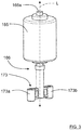
- FIG 7 shows a schematic perspective side view of an alternative transmission axle 166' that has a longitudinal extension L' and comprises a transmission axle rod 166a' and a coupling member 173'.
- the coupling member 173' comprises a first connection rod 183 and a second connection rod 184, where the second connection rod 184 is adapted to be positioned closer to the cutter motor than the first connection rod 183.
- each connection rod 183, 184 comprises two at least partly threaded bores 185a, 185b; 186a, 186b.
- the connection rods 183, 184 run mutually perpendicular to each other, forming a cross-shaped coupling member 173'.
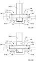
- Figure 8 shows a schematic cut-open side view of a connection portion 164' comprised in a cutting disc
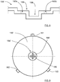
- Figure 9 shows a top view of the cutting disc 160' with the connection portion 164'.
- the connection portion 164' in turn comprises a first slot 188 and a second slot 189, where the first slot 188 is adapted to be positioned closer to the ground in a running condition than the second slot 189, along the vertical extension.
- the first slot 188 is adapted to receive the first connection rod 183 and the second slot 189 is adapted to receive both the first connection rod 183 and a second connection rod 184.
- the coupling member 173' is mounted to the connection portion 164' in a first mounting position where the first connection rod 183 is positioned in the first slot 188 and the second connection rod 184 is positioned in the second slot 189.
- the coupling member 173' is secured to the connection portion 164' by means of screws 187a, 187b that are secured to the bores 186a, 186b in the second connection rod 184.
- the coupling member 173' is mounted to the connection portion 164' in a second mounting position where the first slot 188 is empty and the first connection rod 183 is positioned in the second slot 189.
- the coupling member 173' is secured to the connection portion 164' by means of screws 187a, 187b that run via fastening apertures 190a, 190b in the connection portion 164' and are secured to the bores 185a, 185b in the first connection rod 183.
- the first mounting position corresponds to a first grass cutting height and the second mounting position corresponds to a second grass cutting height where the first grass cutting height exceeds the second grass cutting height.
- the present disclosure relates to a lawn mower 100 comprising a cutter propulsion unit 165, a transmission axle 166, 166' that has a longitudinal extension L, L' and is adapted to be rotated by the cutter propulsion unit 165, and a cutting disc 160 that has a radial extension R that runs between a center 182 and an outer edge 181.
- the cutting disc 160 comprises one or more cutting edges 161, 162, 163 that are adapted to cut grass when the cutting disc 160 is brought into a rotational motion by means of the transmission axle 166.
- the cutting disc 160 further comprises a connection portion 164, 164' which is adapted to receive a coupling member 173, 173', comprised in the transmission axle 166, 166', in at least two different mounting positions that are adapted to position the connection portion 164 in mutually separated positions along the longitudinal extension L, L'.
- connection portion 164 comprises at least two engagement plateau arrangements 170a, 170b; 171a, 171b; 172 which are mutually separated along a vertical extension V that runs perpendicular to the radial extension R.
- Each engagement plateau arrangement 170a, 170b; 171a, 171b; 172 is adapted to receive a coupling member 173 comprised in the transmission axle 166 such that the cutting disc obtains a certain vertical position along the vertical extension V in dependence of which engagement plateau arrangement 170a, 170b; 171a, 171b; 172 that has received the coupling member 173, conferring an associated certain grass cutting height.
- At least one engagement plateau arrangements 170a, 170b; 171a, 171b comprises two opposing surfaces against which the coupling member 173 is adapted to rest.
- the coupling member 173 is adapted to be positioned between two opposing surfaces of at least one engagement plateau arrangement 170a, 170b; 171a, 171b.
- each engagement plateau arrangement 170a, 170b; 171a, 171b; 172 comprises at least one fastening aperture 174a, 174b; 175a, 175b; 176a, 176b
- the coupling member 173 comprises at least one corresponding at least partially threaded bore 178a, 178b, each bore 178a, 178b being adapted to receive a corresponding screw 177a, 177b that runs via the corresponding fastening aperture 174a, 174b; 175a, 175b; 176a, 176b and is adapted to secure the coupling member 173 to the cutting disc 160.
- connection portion 164 comprises coherent arcuate wall portions 179 that encompass surfaces of the engagement plateau arrangements 170a, 170b, 171a, 171b, 172 against which the coupling member 173 is adapted to rest.
- the transmission axle 166' comprises a coupling member 173' which in turn comprises a first connection rod 183 and a second connection rod 184, where the second connection rod 184 is adapted to be positioned closer to the cutter propulsion unit 165 than the first connection rod 183, where the connection portion 164 comprises a first slot 188 and a second slot 189, where the first slot 188 is adapted to be positioned closer to the ground in a running condition than the second slot 188 along a vertical extension V that runs perpendicular to the radial extension R, where the first slot 188 is adapted to receive the first connection rod 183 and the second slot 189 is adapted to receive both the first connection rod 183 and the second connection rod 184.
- the coupling member 173' is secured to the connection portion 164' by means of screws 187a, 187b that run via fastening apertures 190a, 190b in the connection portion 164' and are secured to the bores 185a, 185b of the connection rod 183, 184 that is received in the second slot 189.
- Screws are shown to be used for securing the coupling member 173, 173' to the cutting disc 160 160', other arrangements are of course conceivable.
- locking pins extending perpendicular to the vertical extension, can be used.
- one or more screws can be used for each engagement plateau arrangement 170a, 170b; 171a, 171b; 172 or connection rod 183, 184.
- the bores can be without threads and the screws secured by means of separate locking nuts.
- the cutter motor is generally constituted by a cutter propulsion unit 165.
- the present disclosure also relates to a lawn mower cutting disc 160 that has a radial extension R that runs between a center 182 and an outer edge 181 and comprises one or more cutting edges 161, 162, 163 that are adapted to cut grass when the cutting disc 160 is brought into a rotational motion by means of a transmission axle 166, 166' that has a longitudinal extension L, L'.
- the cutting disc 160 further comprises a connection portion 164, 164' which is adapted to receive a coupling member 173, 173', comprised in the transmission axle 166, 166', in at least two different mounting positions that are adapted to position the connection portion 164 in mutually separated positions along the longitudinal extension L, L'.
- connection portion 164 comprises at least two engagement plateau arrangements 170a, 170b; 171a, 171b; 172 which are mutually separated along a vertical extension V that runs perpendicular to the radial extension R, where each engagement plateau arrangement 170a, 170b; 171a, 171b; 172 is adapted to receive a coupling member 173 comprised in the transmission axle 166 such that the cutting disc can obtain a certain vertical position along the vertical extension V in dependence of which engagement plateau arrangement 170a, 170b; 171a, 171b; 172 that has received the coupling member 173.
- At least one engagement plateau arrangements 170a, 170b; 171a, 171b comprises two opposing surfaces against which the coupling member 173 is adapted to rest.
- connection portion 164 is adapted to receive the coupling member 173 between two opposing surfaces of at least one engagement plateau arrangement 170a, 170b; 171a, 171b.
- each engagement plateau arrangement 170a, 170b; 171a, 171b; 172 comprises at least one fastening aperture 174a, 174b; 175a, 175b; 176a, 176b adapted to admit a screw to pass, enabling the coupling member 173 to be secured to the lawn mower cutting disc 160.
- connection portion 164 comprises coherent arcuate wall portions 179 that encompass surfaces of the engagement plateau arrangements 170a, 170b, 171a, 171b, 172.
- connection portion 164' comprises a first slot 188 and a second slot 189, where, in a running condition, the first slot 188 is adapted to be positioned closer to the ground than the second slot 188 along a vertical extension V that runs perpendicular to the radial extension R, where the first slot 188 is adapted to receive a first connection rod 183 and the second slot 189 is adapted to receive both the first connection rod 183 and a second connection rod 184, the connection rods 183, 184 being comprised in the transmission axle 166'.
- the present disclosure also relates to a lawn mower transmission axle 166, 166' that has a longitudinal extension L, L' and comprises a transmission axle rod 116a, 166a' and a coupling member 173, 173'.
- the transmission axle rod 116a, 166a' is adapted to be rotated by a cutter propulsion unit 165 and the coupling member 173, 173' is adapted to be received by a lawn mower cutting disc connection portion 164, 164' in at least two different mounting positions that are adapted to position the connection portion 164, 164' in mutually separated positions along the longitudinal extension L, L'.
- the coupling member 173 comprises two cylindrical members 173a, 173b positioned on opposite sides of the longitudinal extension L.
- Each cylindrical member 173a, 173b has an axial extension that is parallel to the longitudinal extension L and is formed to correspond to plateau arrangements 170a, 170b, 171a, 171b comprised in the connection portion 164.
- the coupling member 173' comprises a first connection rod 183 and a second connection rod 184, where the second connection rod 184 is adapted to be positioned closer to the cutter propulsion unit 165 than the first connection rod 183.
- the first connection rod 183 is adapted to be received in a first slot 188 in the connection portion 164' and the second connection rod 184 is adapted to be received in a second slot 189 in the connection portion 164'.
- the description above has been directed to a robotic lawn mower, the present disclosure is applicable for any type of lawn mower with at least one motor-powered cutting disc such as for example a robotic lawn mower, a hand-moved lawn mower with or without motor-powered wheels, as well as a riding mower.
Landscapes
- Life Sciences & Earth Sciences (AREA)
- Environmental Sciences (AREA)
- Harvester Elements (AREA)
Applications Claiming Priority (1)
| Application Number | Priority Date | Filing Date | Title |
|---|---|---|---|
| SE2050846A SE544203C2 (en) | 2020-07-06 | 2020-07-06 | Means for adjusting cutting height of a powered lawn mower |
Publications (1)
| Publication Number | Publication Date |
|---|---|
| EP3935933A1 true EP3935933A1 (de) | 2022-01-12 |
Family
ID=76695514
Family Applications (1)
| Application Number | Title | Priority Date | Filing Date |
|---|---|---|---|
| EP21181941.2A Pending EP3935933A1 (de) | 2020-07-06 | 2021-06-28 | Vorrichtung zum einstellen der schnitthöhe eines motorisierten rasenmähers |
Country Status (4)
| Country | Link |
|---|---|
| US (1) | US11844308B2 (de) |
| EP (1) | EP3935933A1 (de) |
| CN (1) | CN113892334A (de) |
| SE (1) | SE544203C2 (de) |
Cited By (1)
| Publication number | Priority date | Publication date | Assignee | Title |
|---|---|---|---|---|
| SE2250532A1 (en) * | 2022-05-02 | 2023-11-03 | Husqvarna Ab | Means for adjusting cutting height of a powered lawn mower |
Families Citing this family (1)
| Publication number | Priority date | Publication date | Assignee | Title |
|---|---|---|---|---|
| US20220183227A1 (en) * | 2020-12-11 | 2022-06-16 | Nanjing Chervon Industry Co., Ltd. | Lawn mower and cutting blade |
Citations (5)
| Publication number | Priority date | Publication date | Assignee | Title |
|---|---|---|---|---|
| EP0531071A1 (de) | 1991-08-30 | 1993-03-10 | Electrolux Outdoor Products Limited | Verbesserungen an Rasenmähern |
| US5205113A (en) * | 1990-05-24 | 1993-04-27 | Fassauer Arthur L | Cutting apparatus mulch recycle system |
| EP0766911A1 (de) | 1995-10-03 | 1997-04-09 | Electrolux Outdoor Products Limited | Höheneinstellvorrichtung für Rasenmäher |
| US5862655A (en) * | 1996-10-03 | 1999-01-26 | Garden Way Incorporated | Adjustable mowing and trimming apparatus |
| CN103621244A (zh) | 2012-08-28 | 2014-03-12 | 苏州宝时得电动工具有限公司 | 割草机 |
Family Cites Families (11)
| Publication number | Priority date | Publication date | Assignee | Title |
|---|---|---|---|---|
| US5894715A (en) * | 1993-09-22 | 1999-04-20 | Briggs & Stratton Corporation | Mounting apparatus for connecting a power head to a device |
| CN109874488B (zh) * | 2016-06-30 | 2022-04-01 | 创科(澳门离岸商业服务)有限公司 | 一种自主式割草机及其导航系统 |
| KR101918994B1 (ko) * | 2017-01-02 | 2019-02-08 | 엘지전자 주식회사 | 잔디깎기 로봇 |
| US11470774B2 (en) * | 2017-07-14 | 2022-10-18 | Irobot Corporation | Blade assembly for a grass cutting mobile robot |
| EP3549427B1 (de) * | 2018-04-06 | 2021-09-01 | LG Electronics Inc. | Rasenmäherroboter |
| CN109601114A (zh) * | 2019-01-30 | 2019-04-12 | 浙江理工大学 | 一种新型除草装置 |
| CN109618646B (zh) * | 2019-02-22 | 2022-04-12 | 浙江白马实业有限公司 | 一种刀盘升降结构和具有该结构的割草机 |
| CN110100563A (zh) * | 2019-06-18 | 2019-08-09 | 广州科语机器人有限公司 | 一种修整刀具及植被修整机 |
| CN110419318A (zh) * | 2019-09-11 | 2019-11-08 | 阳丽萍 | 一种割草刀结构及草坪整平设备 |
| CN110800453B (zh) * | 2019-12-04 | 2020-12-15 | 创客帮(山东)科技服务有限公司 | 一种农业用除草装置 |
| CN110933986B (zh) * | 2019-12-18 | 2021-11-05 | 河南科技大学 | 一种割草机器人割草调高一体化装置及其调高控制方法 |
-
2020
- 2020-07-06 SE SE2050846A patent/SE544203C2/en unknown
-
2021
- 2021-06-28 EP EP21181941.2A patent/EP3935933A1/de active Pending
- 2021-06-30 US US17/363,960 patent/US11844308B2/en active Active
- 2021-07-05 CN CN202110758293.XA patent/CN113892334A/zh active Pending
Patent Citations (6)
| Publication number | Priority date | Publication date | Assignee | Title |
|---|---|---|---|---|
| US5205113A (en) * | 1990-05-24 | 1993-04-27 | Fassauer Arthur L | Cutting apparatus mulch recycle system |
| EP0531071A1 (de) | 1991-08-30 | 1993-03-10 | Electrolux Outdoor Products Limited | Verbesserungen an Rasenmähern |
| EP0766911A1 (de) | 1995-10-03 | 1997-04-09 | Electrolux Outdoor Products Limited | Höheneinstellvorrichtung für Rasenmäher |
| US5862655A (en) * | 1996-10-03 | 1999-01-26 | Garden Way Incorporated | Adjustable mowing and trimming apparatus |
| CN103621244A (zh) | 2012-08-28 | 2014-03-12 | 苏州宝时得电动工具有限公司 | 割草机 |
| CN103621244B (zh) * | 2012-08-28 | 2016-02-17 | 苏州宝时得电动工具有限公司 | 割草机 |
Cited By (3)
| Publication number | Priority date | Publication date | Assignee | Title |
|---|---|---|---|---|
| SE2250532A1 (en) * | 2022-05-02 | 2023-11-03 | Husqvarna Ab | Means for adjusting cutting height of a powered lawn mower |
| EP4272536A1 (de) | 2022-05-02 | 2023-11-08 | Husqvarna AB | Vorrichtung zur einstellung der schnitthöhe eines angetriebenen rasenmähers |
| SE545637C2 (en) * | 2022-05-02 | 2023-11-21 | Husqvarna Ab | Means for adjusting cutting height of a powered lawn mower |
Also Published As
| Publication number | Publication date |
|---|---|
| US20220000020A1 (en) | 2022-01-06 |
| US11844308B2 (en) | 2023-12-19 |
| SE2050846A1 (en) | 2022-01-07 |
| SE544203C2 (en) | 2022-03-01 |
| CN113892334A (zh) | 2022-01-07 |
Similar Documents
| Publication | Publication Date | Title |
|---|---|---|
| EP3935933A1 (de) | Vorrichtung zum einstellen der schnitthöhe eines motorisierten rasenmähers | |
| EP3273766B1 (de) | Verbesserte schlagfestigkeit für ein robotisches arbeitswerkzeug | |
| KR101514507B1 (ko) | 잔디 깎기 기계 | |
| EP0027728A1 (de) | Schneidblatt | |
| EP0808096A1 (de) | Selbstreinigender schneidkopf für mäher | |
| EP3102021B1 (de) | Zum halten eines werkzeugs angepasste plattenfeder, werkzeug, werkzeughalter, robotisches arbeitswerkzeug und ein robotisches arbeitswerkzeugsystem | |
| US20230231436A1 (en) | Electric Motor and Blade Assembly for a Lawn Mower | |
| JPH0783655B2 (ja) | 携帯用作業機 | |
| US5701728A (en) | Lawn mower with line trimmer assembly | |
| US4211060A (en) | Mowing rotor | |
| US11051449B2 (en) | Lawnmower cutting deck with angled cutter shafts | |
| US5383330A (en) | Hand-held edger | |
| EP4272536B1 (de) | Vorrichtung zur einstellung der schnitthöhe eines angetriebenen rasenmähers | |
| US5832704A (en) | Mower blade assembly | |
| CN112166798B (zh) | 割草机 | |
| CN213095292U (zh) | 梳草机 | |
| CN219068922U (zh) | 一种锂电割草机 | |
| CN215582621U (zh) | 一种割草机的调节结构 | |
| CN219421612U (zh) | 割草机刀片组件 | |
| CN216930884U (zh) | 一种打草机 | |
| DK201900057U8 (en) | Improved impact resistance of a robot working tool | |
| US5924494A (en) | Angled arbor for a vertical drive shaft lawn edger | |
| JPS5886012A (ja) | 芝刈り機 | |
| SE505758C3 (sv) | Gräsklippare med vertikalaxlade rotorer och med hjul under åtminstone en rotor samt rotorenhet för en dylik gräsklippare | |
| SE505758C2 (sv) | Gräsklippare med vertikalaxlade rotorer och med hjul under åtminstone en rotor samt rotorenhet för en dylik gräsklippare |
Legal Events
| Date | Code | Title | Description |
|---|---|---|---|
| PUAI | Public reference made under article 153(3) epc to a published international application that has entered the european phase |
Free format text: ORIGINAL CODE: 0009012 |
|
| STAA | Information on the status of an ep patent application or granted ep patent |
Free format text: STATUS: REQUEST FOR EXAMINATION WAS MADE |
|
| 17P | Request for examination filed |
Effective date: 20210628 |
|
| AK | Designated contracting states |
Kind code of ref document: A1 Designated state(s): AL AT BE BG CH CY CZ DE DK EE ES FI FR GB GR HR HU IE IS IT LI LT LU LV MC MK MT NL NO PL PT RO RS SE SI SK SM TR |
|
| B565 | Issuance of search results under rule 164(2) epc |
Effective date: 20211208 |
|
| STAA | Information on the status of an ep patent application or granted ep patent |
Free format text: STATUS: EXAMINATION IS IN PROGRESS |
|
| 17Q | First examination report despatched |
Effective date: 20240213 |