EP3935933A1 - Means for adjusting cutting height of a powered lawn mower - Google Patents
Means for adjusting cutting height of a powered lawn mower Download PDFInfo
- Publication number
- EP3935933A1 EP3935933A1 EP21181941.2A EP21181941A EP3935933A1 EP 3935933 A1 EP3935933 A1 EP 3935933A1 EP 21181941 A EP21181941 A EP 21181941A EP 3935933 A1 EP3935933 A1 EP 3935933A1
- Authority
- EP
- European Patent Office
- Prior art keywords
- coupling member
- lawn mower
- connection portion
- cutting disc
- engagement
- Prior art date
- Legal status (The legal status is an assumption and is not a legal conclusion. Google has not performed a legal analysis and makes no representation as to the accuracy of the status listed.)
- Granted
Links
Images




Classifications
-
- A—HUMAN NECESSITIES
- A01—AGRICULTURE; FORESTRY; ANIMAL HUSBANDRY; HUNTING; TRAPPING; FISHING
- A01D—HARVESTING; MOWING
- A01D34/00—Mowers; Mowing apparatus of harvesters
- A01D34/01—Mowers; Mowing apparatus of harvesters characterised by features relating to the type of cutting apparatus
- A01D34/412—Mowers; Mowing apparatus of harvesters characterised by features relating to the type of cutting apparatus having rotating cutters
- A01D34/63—Mowers; Mowing apparatus of harvesters characterised by features relating to the type of cutting apparatus having rotating cutters having cutters rotating about a vertical axis
-
- A—HUMAN NECESSITIES
- A01—AGRICULTURE; FORESTRY; ANIMAL HUSBANDRY; HUNTING; TRAPPING; FISHING
- A01D—HARVESTING; MOWING
- A01D34/00—Mowers; Mowing apparatus of harvesters
- A01D34/01—Mowers; Mowing apparatus of harvesters characterised by features relating to the type of cutting apparatus
- A01D34/412—Mowers; Mowing apparatus of harvesters characterised by features relating to the type of cutting apparatus having rotating cutters
- A01D34/63—Mowers; Mowing apparatus of harvesters characterised by features relating to the type of cutting apparatus having rotating cutters having cutters rotating about a vertical axis
- A01D34/74—Cutting-height adjustment
-
- A—HUMAN NECESSITIES
- A01—AGRICULTURE; FORESTRY; ANIMAL HUSBANDRY; HUNTING; TRAPPING; FISHING
- A01D—HARVESTING; MOWING
- A01D34/00—Mowers; Mowing apparatus of harvesters
- A01D34/006—Control or measuring arrangements
- A01D34/008—Control or measuring arrangements for automated or remotely controlled operation
-
- A—HUMAN NECESSITIES
- A01—AGRICULTURE; FORESTRY; ANIMAL HUSBANDRY; HUNTING; TRAPPING; FISHING
- A01D—HARVESTING; MOWING
- A01D34/00—Mowers; Mowing apparatus of harvesters
- A01D34/01—Mowers; Mowing apparatus of harvesters characterised by features relating to the type of cutting apparatus
- A01D34/412—Mowers; Mowing apparatus of harvesters characterised by features relating to the type of cutting apparatus having rotating cutters
- A01D34/63—Mowers; Mowing apparatus of harvesters characterised by features relating to the type of cutting apparatus having rotating cutters having cutters rotating about a vertical axis
- A01D34/73—Cutting apparatus
-
- A—HUMAN NECESSITIES
- A01—AGRICULTURE; FORESTRY; ANIMAL HUSBANDRY; HUNTING; TRAPPING; FISHING
- A01D—HARVESTING; MOWING
- A01D34/00—Mowers; Mowing apparatus of harvesters
- A01D34/01—Mowers; Mowing apparatus of harvesters characterised by features relating to the type of cutting apparatus
- A01D34/412—Mowers; Mowing apparatus of harvesters characterised by features relating to the type of cutting apparatus having rotating cutters
- A01D34/63—Mowers; Mowing apparatus of harvesters characterised by features relating to the type of cutting apparatus having rotating cutters having cutters rotating about a vertical axis
- A01D34/73—Cutting apparatus
- A01D34/733—Cutting-blade mounting means
-
- A—HUMAN NECESSITIES
- A01—AGRICULTURE; FORESTRY; ANIMAL HUSBANDRY; HUNTING; TRAPPING; FISHING
- A01D—HARVESTING; MOWING
- A01D34/00—Mowers; Mowing apparatus of harvesters
- A01D34/01—Mowers; Mowing apparatus of harvesters characterised by features relating to the type of cutting apparatus
- A01D34/412—Mowers; Mowing apparatus of harvesters characterised by features relating to the type of cutting apparatus having rotating cutters
- A01D34/63—Mowers; Mowing apparatus of harvesters characterised by features relating to the type of cutting apparatus having rotating cutters having cutters rotating about a vertical axis
- A01D34/76—Driving mechanisms for the cutters
-
- A—HUMAN NECESSITIES
- A01—AGRICULTURE; FORESTRY; ANIMAL HUSBANDRY; HUNTING; TRAPPING; FISHING
- A01D—HARVESTING; MOWING
- A01D2101/00—Lawn-mowers
Definitions
- the present disclosure relates to a powered lawn mower, for example a robotic lawn mower, where the cutting height can be easily adjusted by a user.
- Grass cutting machines are for used for both domestic and commercial applications and can be powered using an electric motor or an internal combustion engine.
- a so-called rotary cutter employs a cutting member which is rotatable in a plane substantially parallel to the ground and about an axis which is normal to the ground, where the cutting member comprises an arm or a disc that is rotably supported in its center and has cutting edges arranged at its ends or its circumference.
- Automated or robotic power tools such as robotic lawn mowers are becoming increasingly more popular.
- a work area such as a garden
- the work area is enclosed by a boundary wire with the purpose of keeping the robotic lawn mower inside the work area.
- An electric control signal may be transmitted through the boundary wire thereby generating an (electro-) magnetic field emanating from the boundary wire.
- the robotic working tool is typically arranged with one or more sensors adapted to sense the control signal.
- the robotic lawn mower can then cut grass on a user's lawn automatically and can be charged automatically without intervention of the user, and no longer needs to be manually managed after being set once.
- the robotic lawn mower typically comprises charging skids for contacting corresponding contact plates in a charging station when docking into the charging station for receiving a charging current through, and possibly also for transferring information by means of electrical communication between the charging station and the robotic lawn mower.
- Most conventional lawn mowers include some means for adjusting the grass cutting height since different users like to cut their lawns to different lengths, and to cut different areas of their lawns to different lengths. This can depend on grow rate of the grass and the cutting frequency of a particular area, as well as on general user desires regarding height of cut grass.
- Most lawn mowers includes means for providing an adjustable height of cutting height, for example wheels or rollers can be connected to a housing in a number of different positions, each position corresponding to a different height of cut, but requires a large number of components in order to adjust the height, and is thus expensive to manufacture.
- Cutting height adjustment can also be made by inserting or removing spacers between the cutter blade and the drive shaft to which the cutter blade is fastened.
- the adjustment involves unbolting the blade from the drive shaft, inserting or removing spacers, and bolting the blade back onto the drive shaft. This operation is relatively cumbersome and time consuming, and requires spacers to be stored.
- EP 531071 discloses displacing a cutting member against a compression spring so as to alter the height of cut of mown grass
- EP 766911 discloses displacing the chassis of a lawn mower to alter the height of cut of mown grass.
- CN 103621244 discloses a mower with a cutterhead and a transmission part that is provided with a matching-connecting face which is connected with the cutterhead in a matched mode.
- the cutterhead is provided with a first installation face and a second installation face, one on each side of the cutter head, for abutting connection with the matching-connecting face.
- the object of the present disclosure is to provide improved and alternative means for an uncomplicated change of grass cutting height of a lawn mower in a more versatile and efficient manner than previously presented, needing lesser parts.
- lawn mower comprising a cutter propulsion unit, a transmission axle that has a longitudinal extension and is adapted to be rotated by the cutter propulsion unit, and a cutting disc that has a radial extension that runs between a center and an outer edge.
- the cutting disc comprises one or more cutting edges that are adapted to cut grass when the cutting disc is brought into a rotational motion by means of the transmission axle.
- the cutting disc further comprises a connection portion which is adapted to receive a coupling member, comprised in the transmission axle, in at least two different mounting positions that are adapted to position the connection portion in mutually separated positions along the longitudinal extension.
- connection portion comprises at least two engagement plateau arrangements which are mutually separated along a vertical extension that runs perpendicular to the radial extension.
- Each engagement plateau arrangement is adapted to receive a coupling member comprised in the transmission axle such that the cutting disc obtains a certain vertical position along the vertical extension in dependence of which engagement plateau arrangement that has received the coupling member, conferring an associated certain grass cutting height.
- the forming of the cutting disc determines the number of grass cutting heights available. Different cutting discs may provide a different number of grass cutting heights, while the coupling member is uncomplicated and universal.
- At least one engagement plateau arrangements comprises two opposing surfaces against which the coupling member is adapted to rest.
- the coupling member is adapted to be positioned between two opposing surfaces of at least one engagement plateau arrangement.
- each engagement plateau arrangement comprises at least one fastening aperture and the coupling member comprises at least one corresponding at least partially threaded bore.
- Each bore is adapted to receive a corresponding screw that runs via the corresponding fastening aperture and is adapted to secure the coupling member to the cutting disc.
- connection portion comprises coherent arcuate wall portions that encompass surfaces of the engagement plateau arrangements against which the coupling member is adapted to rest.
- the transmission axle comprises a coupling member which in turn comprises a first connection rod and a second connection rod.
- the second connection rod is adapted to be positioned closer to the cutter propulsion unit than the first connection rod.
- the connection portion comprises a first slot and a second slot, where the first slot is adapted to be positioned closer to the ground in a running condition than the second slot along a vertical extension that runs perpendicular to the radial extension.
- the first slot is adapted to receive the first connection rod and the second slot is adapted to receive both the first connection rod and the second connection rod.
- the coupling member is secured to the connection portion by means of screws that run via fastening apertures in the connection portion and are secured to the bores of the connection rod that is received in the second slot.
- the present disclosure also relates to cutting discs and transmission axles that are associated with the above advantages.
- FIG 1A shows a perspective view of a robotic lawn mower 100
- Figure 1B shows a schematic overview of the robotic lawn mower 100.
- the robotic lawn mower 100 is adapted for a forward travelling direction D, has a body 140 and a plurality of wheels 130; in this example the robotic lawn mower 100 has four wheels 130, two front wheels and two rear wheels.
- the robotic lawn mower 100 comprises a control unit 110 and at least one electric motor 150 that is comprised in an electric motor arrangement, where at least some of the wheels 130 are drivably connected to at least one electric motor 150. It should be noted that even if the description herein is focused on electric motors, combustion engines may alternatively be used in combination with an electric motor arrangement.
- the robotic lawn mower 100 comprises charging skids 156 for contacting contact plates of a charging station (not shown) when docking into the charging station for receiving a charging current, and possibly also for transferring information by means of electrical communication between the charging station and the robotic lawn mower 100.
- the robotic lawn mower 100 also comprises at least one rechargeable electric power source such as a battery 155 for providing power to the electric motor arrangement 150.
- the battery 155 is arranged to be charged by means of received charging current from the charging station, received through charging skids 156 or other suitable charging connectors.
- the robotic lawn mower 100 also comprises a grass cutting device 160 driven by a cutter motor 165 that also is powered by the battery 155 or, alternatively, by a separate power source.
- the grass cutting device 160 is constituted by a cutting disc 160 that comprises a circumferentially running outer edge 181 and a plurality of cutting edges such as cutting knifes 161, 162, 163 arranged to protrude from the outer edge 181.
- the cutting disc 160 has a centrally located hub or connection portion 164 to which a transmission axle 166 is adapted to be connected.
- each cutting knife 161, 162, 163 is pivotally arranged such that during normal operation they are maintained at a working position due to centripetal forces, radially extending outwards from the cutting disc's center 182.
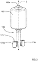
- the transmission axle 166 has a longitudinal extension L and comprises a main axle part 166a and a coupling member 173, where the main axle part 166a is in the form of a rod that is adapted to be brought into rotation by means of the cutter motor 165.
- connection portion 164 comprises a plurality of mounting positions for the transmission axle 166; a first mounting position that is indicated with a dash-double dotted line 167, a second mounting position that is indicated with a dashed line 168 and a third mounting position that is indicated with a dash-dotted line 169.
- the first mounting position 167 corresponds to a first grass cutting height
- the second mounting position 168 corresponds to a second grass cutting height
- the third mounting position 169 corresponds to a third grass cutting height, where the first grass cutting height falls below the second grass cutting height, and where the second grass cutting height falls below the third grass cutting height.
- Each mounting position 167, 168, 169 is associated with a corresponding engagement plateau arrangement 170a, 170b; 171a, 171b; 172, the engagement plateau arrangements 170a, 170b; 171a, 171b; 172 being mutually separated along a vertical extension V that runs perpendicular to a radial extension R that runs between the center 182 and the outer edge 181.
- the vertical extension V also runs along the longitudinal extension L of the transmission axle 166 when the transmission axle 166 is mounted to the cutting disc 160.
- Each engagement plateau arrangement 170a, 170b; 171a, 171b; 172 is adapted to receive the coupling member 173 that is comprised in the transmission axle 166, and to admit the coupling member 173 access to the other engagement plateau arrangements 170a, 170b; 171a, 171b; 172 such that the coupling member 173 can take all mounting positions 167, 168, 169.
- a certain vertical position along the vertical extension V is obtained and thus an associated certain grass cutting height.
- each engagement plateau arrangement 170a, 170b; 171a, 171b; 172 comprises corresponding fastening apertures 174a, 174b; 175a, 175b; 176a, 176b.
- each fastening aperture 174a, 174b; 175a, 175b; 176a, 176b is adapted to receive a fastening means 177a, 177b such as a screw that secures the coupling member 173 to the cutting disc 160 at the chosen mounting position 167, 168, 169.
- the coupling member 173 is mounted to the connection portion 164 in the first mounting position 167 and engages a first engagement plateau arrangement 170a, 170b that is constituted by two opposing surfaces against which the coupling member 173 rests and is secured by the screws 177a, 177b.
- the screws are secured in corresponding at least partly threaded bores 178a, 178b in the coupling member 173.
- the coupling member 173 is mounted to the connection portion 164 in the second mounting position 168 and engages a second engagement plateau arrangement 171a, 171b that is constituted by two opposing surfaces against which the coupling member 173 rests and is secured by the screws 177a, 177b which in turn are secured in the bores 178a, 178b.
- the coupling member 173 is here positioned between the two opposing surfaces of the first engagement plateau arrangement 170a, 170b.
- the coupling member 173 is mounted to the connection portion 164 in the third mounting position 169 and engages a third engagement plateau arrangement 172 that is constituted by an inner bottom surface of the connection portion 164, against which the coupling member 173 rests and is secured by the screws 177a, 177b which in turn are secured in the bores 178a, 178b.
- the coupling member 173 is here positioned between the opposing surfaces of the both the first engagement plateau arrangement 170a, 170b and the second engagement plateau arrangement 171a, 171b.
- connection portion 164 is shown to comprise coherent arcuate wall portions 179 (only one indicated in Figure 2A for reasons of clarity) that encompass the surfaces of the engagement plateau arrangements 170a, 170b, 171a, 171b, 172, where opposing surfaces of the first two engagement plateau arrangements 170a, 170b, 171a, 171b are shown circular.
- These shapes are only an example, and other suitable shapes, such as rectangular or other straight shapes, can of course be used instead.
- the encompassing wall that in this example is formed by the wall parts 179 can be omitted and necessary guidance for the coupling member 173 can be provided by the screws 177a, 177b only or in combination with some other guiding means.
- the coupling member 173 comprises two cylindrical members 173a, 173b positioned on opposite sides of the longitudinal extension L, each cylindrical member 173a, 173b having an axial extension that is parallel to the longitudinal extension L and being formed to correspond to the plateau arrangements 170a, 170b, 171a, 171b.
- Example of other types of guidance means are different types of wall parts and/or slots that correspond to protrusions of the coupling member 173.
- four guiding pins 180 are provided for each engagement plateau arrangement 170a, 170b, 171a, 171b, 172, providing a reliable attachment of the coupling member 173.
- engagement plateau arrangements 170a, 170b, 171a, 171b, 172 there can of course be any suitable number of engagement plateau arrangement. There are at least two engagement plateau arrangements.
- plateau arrangements are of course conceivable, for example the coupling member can comprise different plateaus.
- An further example illustrating another type of plateau arrangement will now be discussed with reference to Figure 7 ,
- FIG 7 shows a schematic perspective side view of an alternative transmission axle 166' that has a longitudinal extension L' and comprises a transmission axle rod 166a' and a coupling member 173'.
- the coupling member 173' comprises a first connection rod 183 and a second connection rod 184, where the second connection rod 184 is adapted to be positioned closer to the cutter motor than the first connection rod 183.
- each connection rod 183, 184 comprises two at least partly threaded bores 185a, 185b; 186a, 186b.
- the connection rods 183, 184 run mutually perpendicular to each other, forming a cross-shaped coupling member 173'.
- Figure 8 shows a schematic cut-open side view of a connection portion 164' comprised in a cutting disc
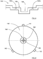
- Figure 9 shows a top view of the cutting disc 160' with the connection portion 164'.
- the connection portion 164' in turn comprises a first slot 188 and a second slot 189, where the first slot 188 is adapted to be positioned closer to the ground in a running condition than the second slot 189, along the vertical extension.
- the first slot 188 is adapted to receive the first connection rod 183 and the second slot 189 is adapted to receive both the first connection rod 183 and a second connection rod 184.
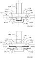
- the coupling member 173' is mounted to the connection portion 164' in a first mounting position where the first connection rod 183 is positioned in the first slot 188 and the second connection rod 184 is positioned in the second slot 189.
- the coupling member 173' is secured to the connection portion 164' by means of screws 187a, 187b that are secured to the bores 186a, 186b in the second connection rod 184.
- the coupling member 173' is mounted to the connection portion 164' in a second mounting position where the first slot 188 is empty and the first connection rod 183 is positioned in the second slot 189.
- the coupling member 173' is secured to the connection portion 164' by means of screws 187a, 187b that run via fastening apertures 190a, 190b in the connection portion 164' and are secured to the bores 185a, 185b in the first connection rod 183.
- the first mounting position corresponds to a first grass cutting height and the second mounting position corresponds to a second grass cutting height where the first grass cutting height exceeds the second grass cutting height.
- the present disclosure relates to a lawn mower 100 comprising a cutter propulsion unit 165, a transmission axle 166, 166' that has a longitudinal extension L, L' and is adapted to be rotated by the cutter propulsion unit 165, and a cutting disc 160 that has a radial extension R that runs between a center 182 and an outer edge 181.
- the cutting disc 160 comprises one or more cutting edges 161, 162, 163 that are adapted to cut grass when the cutting disc 160 is brought into a rotational motion by means of the transmission axle 166.
- the cutting disc 160 further comprises a connection portion 164, 164' which is adapted to receive a coupling member 173, 173', comprised in the transmission axle 166, 166', in at least two different mounting positions that are adapted to position the connection portion 164 in mutually separated positions along the longitudinal extension L, L'.
- connection portion 164 comprises at least two engagement plateau arrangements 170a, 170b; 171a, 171b; 172 which are mutually separated along a vertical extension V that runs perpendicular to the radial extension R.
- Each engagement plateau arrangement 170a, 170b; 171a, 171b; 172 is adapted to receive a coupling member 173 comprised in the transmission axle 166 such that the cutting disc obtains a certain vertical position along the vertical extension V in dependence of which engagement plateau arrangement 170a, 170b; 171a, 171b; 172 that has received the coupling member 173, conferring an associated certain grass cutting height.
- At least one engagement plateau arrangements 170a, 170b; 171a, 171b comprises two opposing surfaces against which the coupling member 173 is adapted to rest.
- the coupling member 173 is adapted to be positioned between two opposing surfaces of at least one engagement plateau arrangement 170a, 170b; 171a, 171b.
- each engagement plateau arrangement 170a, 170b; 171a, 171b; 172 comprises at least one fastening aperture 174a, 174b; 175a, 175b; 176a, 176b
- the coupling member 173 comprises at least one corresponding at least partially threaded bore 178a, 178b, each bore 178a, 178b being adapted to receive a corresponding screw 177a, 177b that runs via the corresponding fastening aperture 174a, 174b; 175a, 175b; 176a, 176b and is adapted to secure the coupling member 173 to the cutting disc 160.
- connection portion 164 comprises coherent arcuate wall portions 179 that encompass surfaces of the engagement plateau arrangements 170a, 170b, 171a, 171b, 172 against which the coupling member 173 is adapted to rest.
- the transmission axle 166' comprises a coupling member 173' which in turn comprises a first connection rod 183 and a second connection rod 184, where the second connection rod 184 is adapted to be positioned closer to the cutter propulsion unit 165 than the first connection rod 183, where the connection portion 164 comprises a first slot 188 and a second slot 189, where the first slot 188 is adapted to be positioned closer to the ground in a running condition than the second slot 188 along a vertical extension V that runs perpendicular to the radial extension R, where the first slot 188 is adapted to receive the first connection rod 183 and the second slot 189 is adapted to receive both the first connection rod 183 and the second connection rod 184.
- the coupling member 173' is secured to the connection portion 164' by means of screws 187a, 187b that run via fastening apertures 190a, 190b in the connection portion 164' and are secured to the bores 185a, 185b of the connection rod 183, 184 that is received in the second slot 189.
- Screws are shown to be used for securing the coupling member 173, 173' to the cutting disc 160 160', other arrangements are of course conceivable.
- locking pins extending perpendicular to the vertical extension, can be used.
- one or more screws can be used for each engagement plateau arrangement 170a, 170b; 171a, 171b; 172 or connection rod 183, 184.
- the bores can be without threads and the screws secured by means of separate locking nuts.
- the cutter motor is generally constituted by a cutter propulsion unit 165.
- the present disclosure also relates to a lawn mower cutting disc 160 that has a radial extension R that runs between a center 182 and an outer edge 181 and comprises one or more cutting edges 161, 162, 163 that are adapted to cut grass when the cutting disc 160 is brought into a rotational motion by means of a transmission axle 166, 166' that has a longitudinal extension L, L'.
- the cutting disc 160 further comprises a connection portion 164, 164' which is adapted to receive a coupling member 173, 173', comprised in the transmission axle 166, 166', in at least two different mounting positions that are adapted to position the connection portion 164 in mutually separated positions along the longitudinal extension L, L'.
- connection portion 164 comprises at least two engagement plateau arrangements 170a, 170b; 171a, 171b; 172 which are mutually separated along a vertical extension V that runs perpendicular to the radial extension R, where each engagement plateau arrangement 170a, 170b; 171a, 171b; 172 is adapted to receive a coupling member 173 comprised in the transmission axle 166 such that the cutting disc can obtain a certain vertical position along the vertical extension V in dependence of which engagement plateau arrangement 170a, 170b; 171a, 171b; 172 that has received the coupling member 173.
- At least one engagement plateau arrangements 170a, 170b; 171a, 171b comprises two opposing surfaces against which the coupling member 173 is adapted to rest.
- connection portion 164 is adapted to receive the coupling member 173 between two opposing surfaces of at least one engagement plateau arrangement 170a, 170b; 171a, 171b.
- each engagement plateau arrangement 170a, 170b; 171a, 171b; 172 comprises at least one fastening aperture 174a, 174b; 175a, 175b; 176a, 176b adapted to admit a screw to pass, enabling the coupling member 173 to be secured to the lawn mower cutting disc 160.
- connection portion 164 comprises coherent arcuate wall portions 179 that encompass surfaces of the engagement plateau arrangements 170a, 170b, 171a, 171b, 172.
- connection portion 164' comprises a first slot 188 and a second slot 189, where, in a running condition, the first slot 188 is adapted to be positioned closer to the ground than the second slot 188 along a vertical extension V that runs perpendicular to the radial extension R, where the first slot 188 is adapted to receive a first connection rod 183 and the second slot 189 is adapted to receive both the first connection rod 183 and a second connection rod 184, the connection rods 183, 184 being comprised in the transmission axle 166'.
- the present disclosure also relates to a lawn mower transmission axle 166, 166' that has a longitudinal extension L, L' and comprises a transmission axle rod 116a, 166a' and a coupling member 173, 173'.
- the transmission axle rod 116a, 166a' is adapted to be rotated by a cutter propulsion unit 165 and the coupling member 173, 173' is adapted to be received by a lawn mower cutting disc connection portion 164, 164' in at least two different mounting positions that are adapted to position the connection portion 164, 164' in mutually separated positions along the longitudinal extension L, L'.
- the coupling member 173 comprises two cylindrical members 173a, 173b positioned on opposite sides of the longitudinal extension L.
- Each cylindrical member 173a, 173b has an axial extension that is parallel to the longitudinal extension L and is formed to correspond to plateau arrangements 170a, 170b, 171a, 171b comprised in the connection portion 164.
- the coupling member 173' comprises a first connection rod 183 and a second connection rod 184, where the second connection rod 184 is adapted to be positioned closer to the cutter propulsion unit 165 than the first connection rod 183.
- the first connection rod 183 is adapted to be received in a first slot 188 in the connection portion 164' and the second connection rod 184 is adapted to be received in a second slot 189 in the connection portion 164'.
- the description above has been directed to a robotic lawn mower, the present disclosure is applicable for any type of lawn mower with at least one motor-powered cutting disc such as for example a robotic lawn mower, a hand-moved lawn mower with or without motor-powered wheels, as well as a riding mower.
Landscapes
- Life Sciences & Earth Sciences (AREA)
- Environmental Sciences (AREA)
- Harvester Elements (AREA)
Abstract
Description
- The present disclosure relates to a powered lawn mower, for example a robotic lawn mower, where the cutting height can be easily adjusted by a user.
- Grass cutting machines are for used for both domestic and commercial applications and can be powered using an electric motor or an internal combustion engine. A so-called rotary cutter employs a cutting member which is rotatable in a plane substantially parallel to the ground and about an axis which is normal to the ground, where the cutting member comprises an arm or a disc that is rotably supported in its center and has cutting edges arranged at its ends or its circumference.
- Automated or robotic power tools such as robotic lawn mowers are becoming increasingly more popular. In a typical deployment a work area, such as a garden, the work area is enclosed by a boundary wire with the purpose of keeping the robotic lawn mower inside the work area. An electric control signal may be transmitted through the boundary wire thereby generating an (electro-) magnetic field emanating from the boundary wire. The robotic working tool is typically arranged with one or more sensors adapted to sense the control signal.
- The robotic lawn mower can then cut grass on a user's lawn automatically and can be charged automatically without intervention of the user, and no longer needs to be manually managed after being set once. The robotic lawn mower typically comprises charging skids for contacting corresponding contact plates in a charging station when docking into the charging station for receiving a charging current through, and possibly also for transferring information by means of electrical communication between the charging station and the robotic lawn mower.
- Most conventional lawn mowers include some means for adjusting the grass cutting height since different users like to cut their lawns to different lengths, and to cut different areas of their lawns to different lengths. This can depend on grow rate of the grass and the cutting frequency of a particular area, as well as on general user desires regarding height of cut grass.
- Most lawn mowers includes means for providing an adjustable height of cutting height, for example wheels or rollers can be connected to a housing in a number of different positions, each position corresponding to a different height of cut, but requires a large number of components in order to adjust the height, and is thus expensive to manufacture.
- Cutting height adjustment can also be made by inserting or removing spacers between the cutter blade and the drive shaft to which the cutter blade is fastened. The adjustment involves unbolting the blade from the drive shaft, inserting or removing spacers, and bolting the blade back onto the drive shaft. This operation is relatively cumbersome and time consuming, and requires spacers to be stored.
-
EP 531071 EP 766911 -
CN 103621244 discloses a mower with a cutterhead and a transmission part that is provided with a matching-connecting face which is connected with the cutterhead in a matched mode. The cutterhead is provided with a first installation face and a second installation face, one on each side of the cutter head, for abutting connection with the matching-connecting face. By turning the cutterhead around, a user can switch between two different cutting heights. - There is thus a need to provide improved and alternative means for an uncomplicated change of grass cutting height of a lawn mower in a more versatile and efficient manner than previously presented, needing lesser parts.
- The object of the present disclosure is to provide improved and alternative means for an uncomplicated change of grass cutting height of a lawn mower in a more versatile and efficient manner than previously presented, needing lesser parts.
- This object is achieved by means of lawn mower comprising a cutter propulsion unit, a transmission axle that has a longitudinal extension and is adapted to be rotated by the cutter propulsion unit, and a cutting disc that has a radial extension that runs between a center and an outer edge. The cutting disc comprises one or more cutting edges that are adapted to cut grass when the cutting disc is brought into a rotational motion by means of the transmission axle. The cutting disc further comprises a connection portion which is adapted to receive a coupling member, comprised in the transmission axle, in at least two different mounting positions that are adapted to position the connection portion in mutually separated positions along the longitudinal extension.
- This enables an uncomplicated change of grass cutting height of a lawn mower in a versatile and efficient manner, needing very few parts, and not needing any special parts to be stored.
- According to some aspects, the connection portion comprises at least two engagement plateau arrangements which are mutually separated along a vertical extension that runs perpendicular to the radial extension. Each engagement plateau arrangement is adapted to receive a coupling member comprised in the transmission axle such that the cutting disc obtains a certain vertical position along the vertical extension in dependence of which engagement plateau arrangement that has received the coupling member, conferring an associated certain grass cutting height.
- In this way, the forming of the cutting disc determines the number of grass cutting heights available. Different cutting discs may provide a different number of grass cutting heights, while the coupling member is uncomplicated and universal.
- According to some aspects, at least one engagement plateau arrangements comprises two opposing surfaces against which the coupling member is adapted to rest.
- This provides a secure and reliable contact between the coupling member and the cutting disc.
- According to some aspects, the coupling member is adapted to be positioned between two opposing surfaces of at least one engagement plateau arrangement.
- In this way, all mounting positions for the coupling member are easily accessible.
- According to some aspects, each engagement plateau arrangement comprises at least one fastening aperture and the coupling member comprises at least one corresponding at least partially threaded bore. Each bore is adapted to receive a corresponding screw that runs via the corresponding fastening aperture and is adapted to secure the coupling member to the cutting disc.
- This enables the coupling member to be easily secured to the cutting disc in a reliable and easily releasable manner.
- According to some aspects, the connection portion comprises coherent arcuate wall portions that encompass surfaces of the engagement plateau arrangements against which the coupling member is adapted to rest.
- This provides an efficient and durable design.
- According to some aspects, the transmission axle comprises a coupling member which in turn comprises a first connection rod and a second connection rod. The second connection rod is adapted to be positioned closer to the cutter propulsion unit than the first connection rod. The connection portion comprises a first slot and a second slot, where the first slot is adapted to be positioned closer to the ground in a running condition than the second slot along a vertical extension that runs perpendicular to the radial extension. The first slot is adapted to receive the first connection rod and the second slot is adapted to receive both the first connection rod and the second connection rod.
- This enables an easily handled change of grass cutting height.
- According to some aspects, the coupling member is secured to the connection portion by means of screws that run via fastening apertures in the connection portion and are secured to the bores of the connection rod that is received in the second slot.
- This enables the coupling member to be easily secured to the cutting disc in a reliable and easily releasable manner.
- The present disclosure also relates to cutting discs and transmission axles that are associated with the above advantages.
- The present disclosure will now be described more in detail with reference to the appended drawings, where:
- Figure 1A
- shows a perspective side view of a robotic lawn mower;
- Figure 1B
- shows a schematic overview of the robotic lawn mower;
- Figure 2A
- shows a perspective top view of a cutting disc;
- Figure 2B
- shows a perspective bottom view of a cutting disc;
- Figure 3
- shows a perspective side view of a cutter motor with a transmission axle;
- Figure 4A
- shows a perspective side view of the cutter motor with the transmission axle connected to the cutting disc in a first mounting position;
- Figure 4B
- shows a section side view of the cutter motor with the transmission axle connected to a cutting disc in the first mounting position;
- Figure 5A
- shows a perspective side view of the cutter motor with the transmission axle connected to the cutting disc in a second mounting position;
- Figure 5B
- shows a section side view of the cutter motor with the transmission axle connected to a cutting disc in the second mounting position;
- Figure 6A
- shows a perspective side view of the cutter motor with the transmission axle connected to the cutting disc in a third mounting position;
- Figure 6B
- shows a section side view of the cutter motor with the transmission axle connected to a cutting disc in the third mounting position;
- Figure 7
- shows a schematic perspective side view of a transmission axle according to a further example;
- Figure 8
- shows a schematic cut-open side view of a cutting disc connection portion according to the further example;
- Figure 9
- shows a schematic top view of the cutting disc according to the further example;
- Figure 10a
- shows a schematic cut-open side view of the transmission axle and the connection portion in a first mounting position; and
- Figure 10b
- shows a schematic cut-open side view of the transmission axle and the connection portion in a first mounting position.
- Aspects of the present disclosure will now be described more fully hereinafter with reference to the accompanying drawings. The different devices, systems, computer programs and methods disclosed herein can, however, be realized in many different forms and should not be construed as being limited to the aspects set forth herein. Like numbers in the drawings refer to like elements throughout.
- The terminology used herein is for describing aspects of the disclosure only and is not intended to limit the invention. As used herein, the singular forms "a", "an" and "the" are intended to include the plural forms as well, unless the context clearly indicates otherwise.
- It should be noted that even though the description given herein will be focused on robotic lawn mowers, the teachings herein may also be applied to any type of lawn mower with a rotary cutter.
-
Figure 1A shows a perspective view of arobotic lawn mower 100 andFigure 1B shows a schematic overview of therobotic lawn mower 100. Therobotic lawn mower 100 is adapted for a forward travelling direction D, has abody 140 and a plurality ofwheels 130; in this example therobotic lawn mower 100 has fourwheels 130, two front wheels and two rear wheels. Therobotic lawn mower 100 comprises acontrol unit 110 and at least oneelectric motor 150 that is comprised in an electric motor arrangement, where at least some of thewheels 130 are drivably connected to at least oneelectric motor 150. It should be noted that even if the description herein is focused on electric motors, combustion engines may alternatively be used in combination with an electric motor arrangement. - The
robotic lawn mower 100 comprises chargingskids 156 for contacting contact plates of a charging station (not shown) when docking into the charging station for receiving a charging current, and possibly also for transferring information by means of electrical communication between the charging station and therobotic lawn mower 100. - The
robotic lawn mower 100 also comprises at least one rechargeable electric power source such as abattery 155 for providing power to theelectric motor arrangement 150. Thebattery 155 is arranged to be charged by means of received charging current from the charging station, received through chargingskids 156 or other suitable charging connectors. - The
robotic lawn mower 100 also comprises agrass cutting device 160 driven by acutter motor 165 that also is powered by thebattery 155 or, alternatively, by a separate power source. - In this example, as shown in
Figure 2A andFigure 2B , thegrass cutting device 160 is constituted by acutting disc 160 that comprises a circumferentially runningouter edge 181 and a plurality of cutting edges such as cuttingknifes outer edge 181. With reference also toFigure 3 , thecutting disc 160 has a centrally located hub orconnection portion 164 to which atransmission axle 166 is adapted to be connected. According to some aspects, each cuttingknife center 182. If an object that is more resilient than ordinary grass is encountered, the cutting knifes 161, 162, 163 are adapted to pivot, avoiding damage to both the object and the cutting knifes 161, 162, 163. Other types of cutting edges and number of cutting edges are of course conceivable. Thetransmission axle 166 has a longitudinal extension L and comprises amain axle part 166a and acoupling member 173, where themain axle part 166a is in the form of a rod that is adapted to be brought into rotation by means of thecutter motor 165. - According to the present disclosure, the
connection portion 164 comprises a plurality of mounting positions for thetransmission axle 166; a first mounting position that is indicated with a dash-doubledotted line 167, a second mounting position that is indicated with a dashedline 168 and a third mounting position that is indicated with a dash-dottedline 169. Thefirst mounting position 167 corresponds to a first grass cutting height, thesecond mounting position 168 corresponds to a second grass cutting height and thethird mounting position 169 corresponds to a third grass cutting height, where the first grass cutting height falls below the second grass cutting height, and where the second grass cutting height falls below the third grass cutting height. - Each mounting
position engagement plateau arrangement engagement plateau arrangements center 182 and theouter edge 181. The vertical extension V also runs along the longitudinal extension L of thetransmission axle 166 when thetransmission axle 166 is mounted to thecutting disc 160. - Each
engagement plateau arrangement coupling member 173 that is comprised in thetransmission axle 166, and to admit thecoupling member 173 access to the otherengagement plateau arrangements coupling member 173 can take all mountingpositions coupling member 163 engage thecutting disc 160 using a certainengagement plateau arrangement - In order to secure the
coupling member 173 to a certainengagement plateau arrangement engagement plateau arrangement fastening apertures Figure 4B , eachfastening aperture coupling member 173 to thecutting disc 160 at the chosen mountingposition - In the present example there are three mounting positions that will be described more in detail in the following.
- With reference to
Figure 2A ,Figure 2B ,Figure 3 ,Figure 4A and Figure 4B , thecoupling member 173 is mounted to theconnection portion 164 in thefirst mounting position 167 and engages a firstengagement plateau arrangement coupling member 173 rests and is secured by thescrews bores coupling member 173. - With reference to
Figure 2A ,Figure 2B ,Figure 3 ,Figure 5A and Figure 5B , thecoupling member 173 is mounted to theconnection portion 164 in thesecond mounting position 168 and engages a secondengagement plateau arrangement coupling member 173 rests and is secured by thescrews bores coupling member 173 is here positioned between the two opposing surfaces of the firstengagement plateau arrangement - With reference to
Figure 2A ,Figure 2B ,Figure 3 ,Figure 6A and Figure 6B , thecoupling member 173 is mounted to theconnection portion 164 in thethird mounting position 169 and engages a thirdengagement plateau arrangement 172 that is constituted by an inner bottom surface of theconnection portion 164, against which thecoupling member 173 rests and is secured by thescrews bores coupling member 173 is here positioned between the opposing surfaces of the both the firstengagement plateau arrangement engagement plateau arrangement - Three different grass cutting heights are thus easily achieved by switching between the above mounting
positions cutter motor 165 can remain fixed to thebody 140 or an internal frame, reducing the number of parts and complexity. - The present disclosure is not limited to the above, but may vary freely within the scope of the appended claims. For example, the
connection portion 164 is shown to comprise coherent arcuate wall portions 179 (only one indicated inFigure 2A for reasons of clarity) that encompass the surfaces of theengagement plateau arrangements engagement plateau arrangements wall parts 179 can be omitted and necessary guidance for thecoupling member 173 can be provided by thescrews - As shown in
Figure 3 , in the case of opposing surfaces of the first twoengagement plateau arrangements coupling member 173 comprises twocylindrical members cylindrical member plateau arrangements - Example of other types of guidance means are different types of wall parts and/or slots that correspond to protrusions of the
coupling member 173. In this example, four guiding pins 180 (only one indicated inFigure 2A for reasons of clarity) are provided for eachengagement plateau arrangement coupling member 173. - In the examples provided there are three
engagement plateau arrangements - Other types of plateau arrangements are of course conceivable, for example the coupling member can comprise different plateaus. An further example illustrating another type of plateau arrangement will now be discussed with reference to
Figure 7 , -
Figure 8, Figure 9 ,Figure 10A and Figure 10B .Figure 7 shows a schematic perspective side view of an alternative transmission axle 166' that has a longitudinal extension L' and comprises atransmission axle rod 166a' and acoupling member 173'. Thecoupling member 173' comprises afirst connection rod 183 and asecond connection rod 184, where thesecond connection rod 184 is adapted to be positioned closer to the cutter motor than thefirst connection rod 183. According to some aspects, eachconnection rod bores connection rods cross-shaped coupling member 173'. -
Figure 8 shows a schematic cut-open side view of a connection portion 164' comprised in a cutting disc, andFigure 9 shows a top view of the cutting disc 160' with the connection portion 164'. The connection portion 164' in turn comprises afirst slot 188 and asecond slot 189, where thefirst slot 188 is adapted to be positioned closer to the ground in a running condition than thesecond slot 189, along the vertical extension. Thefirst slot 188 is adapted to receive thefirst connection rod 183 and thesecond slot 189 is adapted to receive both thefirst connection rod 183 and asecond connection rod 184. - In
Figure 10A , showing a schematic cut-open side view of the transmission axle 166' and the connection portion 164', thecoupling member 173' is mounted to the connection portion 164' in a first mounting position where thefirst connection rod 183 is positioned in thefirst slot 188 and thesecond connection rod 184 is positioned in thesecond slot 189. According to some aspects, thecoupling member 173' is secured to the connection portion 164' by means ofscrews bores second connection rod 184. - In
Figure 10B , that corresponds toFigure 10A , thecoupling member 173' is mounted to the connection portion 164' in a second mounting position where thefirst slot 188 is empty and thefirst connection rod 183 is positioned in thesecond slot 189. According to some aspects, thecoupling member 173' is secured to the connection portion 164' by means ofscrews fastening apertures bores first connection rod 183. - The first mounting position corresponds to a first grass cutting height and the second mounting position corresponds to a second grass cutting height where the first grass cutting height exceeds the second grass cutting height.
- Generally, the present disclosure relates to a
lawn mower 100 comprising acutter propulsion unit 165, atransmission axle 166, 166' that has a longitudinal extension L, L' and is adapted to be rotated by thecutter propulsion unit 165, and acutting disc 160 that has a radial extension R that runs between acenter 182 and anouter edge 181. Thecutting disc 160 comprises one ormore cutting edges cutting disc 160 is brought into a rotational motion by means of thetransmission axle 166. Thecutting disc 160 further comprises aconnection portion 164, 164' which is adapted to receive acoupling member transmission axle 166, 166', in at least two different mounting positions that are adapted to position theconnection portion 164 in mutually separated positions along the longitudinal extension L, L'. - According to some aspects, the
connection portion 164 comprises at least twoengagement plateau arrangements engagement plateau arrangement coupling member 173 comprised in thetransmission axle 166 such that the cutting disc obtains a certain vertical position along the vertical extension V in dependence of whichengagement plateau arrangement coupling member 173, conferring an associated certain grass cutting height. - According to some aspects, at least one
engagement plateau arrangements coupling member 173 is adapted to rest. - According to some aspects, the
coupling member 173 is adapted to be positioned between two opposing surfaces of at least oneengagement plateau arrangement - According to some aspects, each
engagement plateau arrangement fastening aperture coupling member 173 comprises at least one corresponding at least partially threadedbore bore corresponding screw corresponding fastening aperture coupling member 173 to thecutting disc 160. - According to some aspects, the
connection portion 164 comprises coherentarcuate wall portions 179 that encompass surfaces of theengagement plateau arrangements coupling member 173 is adapted to rest. - According to some aspects, the transmission axle 166' comprises a
coupling member 173' which in turn comprises afirst connection rod 183 and asecond connection rod 184, where thesecond connection rod 184 is adapted to be positioned closer to thecutter propulsion unit 165 than thefirst connection rod 183, where theconnection portion 164 comprises afirst slot 188 and asecond slot 189, where thefirst slot 188 is adapted to be positioned closer to the ground in a running condition than thesecond slot 188 along a vertical extension V that runs perpendicular to the radial extension R, where thefirst slot 188 is adapted to receive thefirst connection rod 183 and thesecond slot 189 is adapted to receive both thefirst connection rod 183 and thesecond connection rod 184. - According to some aspects, the
coupling member 173' is secured to the connection portion 164' by means ofscrews fastening apertures bores connection rod second slot 189. - Screws are shown to be used for securing the
coupling member cutting disc 160 160', other arrangements are of course conceivable. For example locking pins, extending perpendicular to the vertical extension, can be used. - In the case of screws, one or more screws can be used for each
engagement plateau arrangement connection rod - The cutter motor is generally constituted by a
cutter propulsion unit 165. - The present disclosure also relates to a lawn
mower cutting disc 160 that has a radial extension R that runs between acenter 182 and anouter edge 181 and comprises one ormore cutting edges cutting disc 160 is brought into a rotational motion by means of atransmission axle 166, 166' that has a longitudinal extension L, L'. Thecutting disc 160 further comprises aconnection portion 164, 164' which is adapted to receive acoupling member transmission axle 166, 166', in at least two different mounting positions that are adapted to position theconnection portion 164 in mutually separated positions along the longitudinal extension L, L'. - According to some aspects, the
connection portion 164 comprises at least twoengagement plateau arrangements engagement plateau arrangement coupling member 173 comprised in thetransmission axle 166 such that the cutting disc can obtain a certain vertical position along the vertical extension V in dependence of whichengagement plateau arrangement coupling member 173. - According to some aspects, at least one
engagement plateau arrangements coupling member 173 is adapted to rest. - According to some aspects, the
connection portion 164 is adapted to receive thecoupling member 173 between two opposing surfaces of at least oneengagement plateau arrangement - According to some aspects, each
engagement plateau arrangement fastening aperture coupling member 173 to be secured to the lawnmower cutting disc 160. - According to some aspects, the
connection portion 164 comprises coherentarcuate wall portions 179 that encompass surfaces of theengagement plateau arrangements - According to some aspects, the connection portion 164' comprises a
first slot 188 and asecond slot 189, where, in a running condition, thefirst slot 188 is adapted to be positioned closer to the ground than thesecond slot 188 along a vertical extension V that runs perpendicular to the radial extension R, where thefirst slot 188 is adapted to receive afirst connection rod 183 and thesecond slot 189 is adapted to receive both thefirst connection rod 183 and asecond connection rod 184, theconnection rods - The present disclosure also relates to a lawn
mower transmission axle 166, 166' that has a longitudinal extension L, L' and comprises atransmission axle rod 116a, 166a' and acoupling member transmission axle rod 116a, 166a' is adapted to be rotated by acutter propulsion unit 165 and thecoupling member disc connection portion 164, 164' in at least two different mounting positions that are adapted to position theconnection portion 164, 164' in mutually separated positions along the longitudinal extension L, L'. - According to some aspects, the
coupling member 173 comprises twocylindrical members cylindrical member plateau arrangements connection portion 164. - According to some aspects, the
coupling member 173' comprises afirst connection rod 183 and asecond connection rod 184, where thesecond connection rod 184 is adapted to be positioned closer to thecutter propulsion unit 165 than thefirst connection rod 183. Thefirst connection rod 183 is adapted to be received in afirst slot 188 in the connection portion 164' and thesecond connection rod 184 is adapted to be received in asecond slot 189 in the connection portion 164'. - Although the description above has been directed to a robotic lawn mower, the present disclosure is applicable for any type of lawn mower with at least one motor-powered cutting disc such as for example a robotic lawn mower, a hand-moved lawn mower with or without motor-powered wheels, as well as a riding mower.
Claims (18)
- A lawn mower (100) comprising a cutter propulsion unit (165), a transmission axle (166, 166') that has a longitudinal extension (L, L') and is adapted to be rotated by the cutter propulsion unit (165), and a cutting disc (160) that has a radial extension (R) that runs between a center (182) and an outer edge (181), where the cutting disc (160) comprises one or more cutting edges (161, 162, 163) that are adapted to cut grass when the cutting disc (160) is brought into a rotational motion by means of the transmission axle (166), wherein the cutting disc (160) further comprises a connection portion (164, 164') which is adapted to receive a coupling member (173, 173'), comprised in the transmission axle (166, 166'), in at least two different mounting positions that are adapted to position the connection portion (164) in mutually separated positions along the longitudinal extension (L, L').
- The lawn mower (100) according to claim 1, wherein the connection portion (164) comprises at least two engagement plateau arrangements (170a, 170b; 171a, 171b; 172) which are mutually separated along a vertical extension (V) that runs perpendicular to the radial extension (R), each engagement plateau arrangement (170a, 170b; 171a, 171b; 172) being adapted to receive a coupling member (173) comprised in the transmission axle (166) such that the cutting disc obtains a certain vertical position along the vertical extension (V) in dependence of which engagement plateau arrangement (170a, 170b; 171a, 171b; 172) that has received the coupling member (173), conferring an associated certain grass cutting height.
- The lawn mower (100) according to claim 2, wherein at least one engagement plateau arrangements (170a, 170b; 171a, 171b) comprises two opposing surfaces against which the coupling member (173) is adapted to rest.
- The lawn mower (100) according to any one of the claims 2 or 3, wherein the coupling member (173) is adapted to be positioned between two opposing surfaces of at least one engagement plateau arrangement (170a, 170b; 171a, 171b).
- The lawn mower (100) according to any one of the claims 2-4, wherein each engagement plateau arrangement (170a, 170b; 171a, 171b; 172) comprises at least one fastening aperture (174a, 174b; 175a, 175b; 176a, 176b), where the coupling member (173) comprises at least one corresponding at least partially threaded bore (178a, 178b), each bore (178a, 178b) being adapted to receive a corresponding screw (177a, 177b) that runs via the corresponding fastening aperture (174a, 174b; 175a, 175b; 176a, 176b) and is adapted to secure the coupling member (173) to the cutting disc (160).
- The lawn mower (100) according to any one of the claims 2-5, wherein the connection portion (164) comprises coherent arcuate wall portions (179) that encompass surfaces of the engagement plateau arrangements (170a, 170b, 171a, 171b, 172) against which the coupling member (173) is adapted to rest.
- The lawn mower (100) according to claim 1, wherein the transmission axle (166') comprises a coupling member (173') which in turn comprises a first connection rod (183) and a second connection rod (184), where the second connection rod (184) is adapted to be positioned closer to the cutter propulsion unit (165) than the first connection rod (183), where the connection portion (164) comprises a first slot (188) and a second slot (189), where the first slot (188) is adapted to be positioned closer to the ground in a running condition than the second slot (188) along a vertical extension (V) that runs perpendicular to the radial extension (R), where the first slot (188) is adapted to receive the first connection rod (183) and the second slot (189) is adapted to receive both the first connection rod (183) and the second connection rod (184).
- The lawn mower (100) according to claim 7, wherein the coupling member (173') is secured to the connection portion (164') by means of screws (187a, 187b) that run via fastening apertures (190a, 190b) in the connection portion (164') and are secured to the bores (185a, 185b) of the connection rod (183, 184) that is received in the second slot (189).
- A lawn mower cutting disc (160) that has a radial extension (R) that runs between a center (182) and an outer edge (181) and comprises one or more cutting edges (161, 162, 163) that are adapted to cut grass when the cutting disc (160) is brought into a rotational motion by means of a transmission axle (166, 166') that has a longitudinal extension (L, L'), wherein the cutting disc (160) further comprises a connection portion (164, 164') which is adapted to receive a coupling member (173, 173'), comprised in the transmission axle (166, 166'), in at least two different mounting positions that are adapted to position the connection portion (164) in mutually separated positions along the longitudinal extension (L, L').
- The lawn mower cutting disc (160) according to claim 9, wherein the connection portion (164) comprises at least two engagement plateau arrangements (170a, 170b; 171a, 171b; 172) which are mutually separated along a vertical extension (V) that runs perpendicular to the radial extension (R), where each engagement plateau arrangement (170a, 170b; 171a, 171b; 172) is adapted to receive a coupling member (173) comprised in the transmission axle (166) such that the cutting disc can obtain a certain vertical position along the vertical extension (V) in dependence of which engagement plateau arrangement (170a, 170b; 171a, 171b; 172) that has received the coupling member (173).
- The lawn mower cutting disc (160) according to claim 10, wherein at least one engagement plateau arrangements (170a, 170b; 171a, 171b) comprises two opposing surfaces against which the coupling member (173) is adapted to rest.
- The lawn mower cutting disc (160) according to any one of the claims 10 or 11, wherein the connection portion (164) is adapted to receive the coupling member (173) between two opposing surfaces of at least one engagement plateau arrangement (170a, 170b; 171a, 171b).
- The lawn mower cutting disc (160) according to any one of the claims 10-12, wherein each engagement plateau arrangement (170a, 170b; 171a, 171b; 172) comprises at least one fastening aperture (174a, 174b; 175a, 175b; 176a, 176b) adapted to admit a screw to pass, enabling the coupling member (173) to be secured to the lawn mower cutting disc (160).
- The lawn mower cutting disc (160) according to any one of the claims 10-13, wherein the connection portion (164) comprises coherent arcuate wall portions (179) that encompass surfaces of the engagement plateau arrangements (170a, 170b, 171a, 171b, 172).
- The lawn mower cutting disc (160) according to claim 10, wherein the connection portion (164') comprises a first slot (188) and a second slot (189), where, in a running condition, the first slot (188) is adapted to be positioned closer to the ground than the second slot (188) along a vertical extension (V) that runs perpendicular to the radial extension (R), where the first slot (188) is adapted to receive a first connection rod (183) and the second slot (189) is adapted to receive both the first connection rod (183) and a second connection rod (184), the connection rods (183, 184) being comprised in the transmission axle (166').
- A lawn mower transmission axle (166, 166') that has a longitudinal extension (L, L') and comprises a transmission axle rod (116a, 166a') and a coupling member (173, 173'), where the transmission axle rod (116a, 166a') is adapted to be rotated by a cutter propulsion unit (165) and wherein the coupling member (173, 173') is adapted to be received by a lawn mower cutting disc connection portion (164, 164') in at least two different mounting positions that are adapted to position the connection portion (164, 164') in mutually separated positions along the longitudinal extension (L, L').
- The transmission axle (166, 166') according to claim 16, wherein the coupling member (173) comprises two cylindrical members (173a, 173b) positioned on opposite sides of the longitudinal extension (L), each cylindrical member (173a, 173b) having an axial extension that is parallel to the longitudinal extension (L) and being formed to correspond to plateau arrangements (170a, 170b, 171a, 171b) comprised in the connection portion (164).
- The transmission axle (166, 166') according to claim 16, wherein the coupling member (173') comprises a first connection rod (183) and a second connection rod (184), where the second connection rod (184) is adapted to be positioned closer to the cutter propulsion unit (165) than the first connection rod (183), the first connection rod (183) being adapted to be received in a first slot (188) in the connection portion (164') and the second connection rod (184) being adapted to be received in a second slot (189) in the connection portion (164').
Applications Claiming Priority (1)
| Application Number | Priority Date | Filing Date | Title |
|---|---|---|---|
| SE2050846A SE544203C2 (en) | 2020-07-06 | 2020-07-06 | Means for adjusting cutting height of a powered lawn mower |
Publications (2)
| Publication Number | Publication Date |
|---|---|
| EP3935933A1 true EP3935933A1 (en) | 2022-01-12 |
| EP3935933B1 EP3935933B1 (en) | 2026-01-28 |
Family
ID=76695514
Family Applications (1)
| Application Number | Title | Priority Date | Filing Date |
|---|---|---|---|
| EP21181941.2A Active EP3935933B1 (en) | 2020-07-06 | 2021-06-28 | Means for adjusting cutting height of a powered lawn mower |
Country Status (4)
| Country | Link |
|---|---|
| US (1) | US11844308B2 (en) |
| EP (1) | EP3935933B1 (en) |
| CN (1) | CN113892334B (en) |
| SE (1) | SE544203C2 (en) |
Cited By (1)
| Publication number | Priority date | Publication date | Assignee | Title |
|---|---|---|---|---|
| SE2250532A1 (en) * | 2022-05-02 | 2023-11-03 | Husqvarna Ab | Means for adjusting cutting height of a powered lawn mower |
Families Citing this family (1)
| Publication number | Priority date | Publication date | Assignee | Title |
|---|---|---|---|---|
| US12414502B2 (en) * | 2020-12-11 | 2025-09-16 | Nanjing Chervon Industry Co., Ltd. | Lawn mower and cutting blade |
Citations (5)
| Publication number | Priority date | Publication date | Assignee | Title |
|---|---|---|---|---|
| EP0531071A1 (en) | 1991-08-30 | 1993-03-10 | Electrolux Outdoor Products Limited | Improvements in and relating to grass cutting machines |
| US5205113A (en) * | 1990-05-24 | 1993-04-27 | Fassauer Arthur L | Cutting apparatus mulch recycle system |
| EP0766911A1 (en) | 1995-10-03 | 1997-04-09 | Electrolux Outdoor Products Limited | Cutting-height adjustment for lawnmower |
| US5862655A (en) * | 1996-10-03 | 1999-01-26 | Garden Way Incorporated | Adjustable mowing and trimming apparatus |
| CN103621244A (en) | 2012-08-28 | 2014-03-12 | 苏州宝时得电动工具有限公司 | Hay mower |
Family Cites Families (16)
| Publication number | Priority date | Publication date | Assignee | Title |
|---|---|---|---|---|
| DE2531420C2 (en) * | 1975-07-14 | 1985-04-25 | Maschinenfabrik Fahr Ag Gottmadingen, 7702 Gottmadingen | mower |
| GB8411663D0 (en) * | 1984-05-08 | 1984-06-13 | Pa Technology Ltd | Rotary lawnmowers |
| US5894715A (en) * | 1993-09-22 | 1999-04-20 | Briggs & Stratton Corporation | Mounting apparatus for connecting a power head to a device |
| CN109416543B (en) * | 2016-06-30 | 2022-11-08 | 创科(澳门离岸商业服务)有限公司 | Autonomous mower and navigation system thereof |
| KR101918994B1 (en) * | 2017-01-02 | 2019-02-08 | 엘지전자 주식회사 | Lawn mower robot |
| US11470774B2 (en) * | 2017-07-14 | 2022-10-18 | Irobot Corporation | Blade assembly for a grass cutting mobile robot |
| CN107493805B (en) * | 2017-09-26 | 2022-12-02 | 钱江集团温岭正峰动力有限公司 | Tool bit height adjusting structure of edge trimming machine |
| CN107593093A (en) * | 2017-10-16 | 2018-01-19 | 四川冠腾科技有限公司 | A kind of weeder for being conveniently replaceable cutter |
| EP3549427B1 (en) * | 2018-04-06 | 2021-09-01 | LG Electronics Inc. | Lawn mower robot |
| CN109601114A (en) * | 2019-01-30 | 2019-04-12 | 浙江理工大学 | A new type of weeding device |
| CN109618646B (en) * | 2019-02-22 | 2022-04-12 | 浙江白马实业有限公司 | A cutter head lifting structure and a lawn mower with the same |
| CN209768224U (en) * | 2019-03-15 | 2019-12-13 | 甘肃绿园生态种养殖家庭农场 | Special weeding equipment of licorice |
| CN110100563A (en) * | 2019-06-18 | 2019-08-09 | 广州科语机器人有限公司 | A kind of dressing tool and vegetation finishing machine |
| CN110419318A (en) * | 2019-09-11 | 2019-11-08 | 阳丽萍 | A kind of hay knife structure and lawn levelling means |
| CN110800453B (en) * | 2019-12-04 | 2020-12-15 | 创客帮(山东)科技服务有限公司 | Weeding device for agricultural |
| CN110933986B (en) * | 2019-12-18 | 2021-11-05 | 河南科技大学 | A lawn mowing robot mowing height adjustment integrated device and its height adjustment control method |
-
2020
- 2020-07-06 SE SE2050846A patent/SE544203C2/en unknown
-
2021
- 2021-06-28 EP EP21181941.2A patent/EP3935933B1/en active Active
- 2021-06-30 US US17/363,960 patent/US11844308B2/en active Active
- 2021-07-05 CN CN202110758293.XA patent/CN113892334B/en active Active
Patent Citations (6)
| Publication number | Priority date | Publication date | Assignee | Title |
|---|---|---|---|---|
| US5205113A (en) * | 1990-05-24 | 1993-04-27 | Fassauer Arthur L | Cutting apparatus mulch recycle system |
| EP0531071A1 (en) | 1991-08-30 | 1993-03-10 | Electrolux Outdoor Products Limited | Improvements in and relating to grass cutting machines |
| EP0766911A1 (en) | 1995-10-03 | 1997-04-09 | Electrolux Outdoor Products Limited | Cutting-height adjustment for lawnmower |
| US5862655A (en) * | 1996-10-03 | 1999-01-26 | Garden Way Incorporated | Adjustable mowing and trimming apparatus |
| CN103621244A (en) | 2012-08-28 | 2014-03-12 | 苏州宝时得电动工具有限公司 | Hay mower |
| CN103621244B (en) * | 2012-08-28 | 2016-02-17 | 苏州宝时得电动工具有限公司 | Mower |
Cited By (3)
| Publication number | Priority date | Publication date | Assignee | Title |
|---|---|---|---|---|
| SE2250532A1 (en) * | 2022-05-02 | 2023-11-03 | Husqvarna Ab | Means for adjusting cutting height of a powered lawn mower |
| EP4272536A1 (en) | 2022-05-02 | 2023-11-08 | Husqvarna AB | Means for adjusting cutting height of a powered lawn mower |
| SE545637C2 (en) * | 2022-05-02 | 2023-11-21 | Husqvarna Ab | Means for adjusting cutting height of a powered lawn mower |
Also Published As
| Publication number | Publication date |
|---|---|
| US11844308B2 (en) | 2023-12-19 |
| CN113892334B (en) | 2025-05-23 |
| CN113892334A (en) | 2022-01-07 |
| SE2050846A1 (en) | 2022-01-07 |
| US20220000020A1 (en) | 2022-01-06 |
| SE544203C2 (en) | 2022-03-01 |
| EP3935933B1 (en) | 2026-01-28 |
Similar Documents
| Publication | Publication Date | Title |
|---|---|---|
| EP3273766B1 (en) | Improved impact resistance for a robotic working tool | |
| US20230344300A1 (en) | Electric Motor and Blade Assembly for a Lawn Mower | |
| KR101514507B1 (en) | Lawn mower | |
| EP3935933B1 (en) | Means for adjusting cutting height of a powered lawn mower | |
| US4302878A (en) | Cutting blade | |
| EP3102021B1 (en) | The claimed invention concerns a plate spring adapted to hold a tool, a tool, a tool holder, a robotic work tool and a robotic working tool system | |
| EP3772891B1 (en) | Lawnmower cutting deck, lawnmower, and method of mowing a lawn | |
| CA2329967A1 (en) | Mower reels with enhanced cutting | |
| EP4272536B1 (en) | Means for adjusting cutting height of a powered lawn mower | |
| US5701728A (en) | Lawn mower with line trimmer assembly | |
| US4211060A (en) | Mowing rotor | |
| US5383330A (en) | Hand-held edger | |
| US5832704A (en) | Mower blade assembly | |
| CN219068922U (en) | Lithium battery mower | |
| CN219421612U (en) | Mower blade assembly | |
| CN213095292U (en) | Grass combing machine | |
| CN215582621U (en) | Adjusting structure of mower | |
| JPS6311415Y2 (en) | ||
| US5924494A (en) | Angled arbor for a vertical drive shaft lawn edger | |
| JP2517971Y2 (en) | Lawn mower blade unit | |
| DK201900057U8 (en) | Improved impact resistance of a robot working tool | |
| JPH0226271Y2 (en) | ||
| JPH0515223A (en) | Lawn mower | |
| SE505758C3 (en) | Lawnmower with vertical axis rotors and with wheels under at least one rotor and rotor unit for such a lawnmower | |
| SE505758C2 (en) | Lawn mower with vertical axis rotors and wheels under at least one rotor and rotor unit for such a lawnmower |
Legal Events
| Date | Code | Title | Description |
|---|---|---|---|
| PUAI | Public reference made under article 153(3) epc to a published international application that has entered the european phase |
Free format text: ORIGINAL CODE: 0009012 |
|
| STAA | Information on the status of an ep patent application or granted ep patent |
Free format text: STATUS: REQUEST FOR EXAMINATION WAS MADE |
|
| 17P | Request for examination filed |
Effective date: 20210628 |
|
| AK | Designated contracting states |
Kind code of ref document: A1 Designated state(s): AL AT BE BG CH CY CZ DE DK EE ES FI FR GB GR HR HU IE IS IT LI LT LU LV MC MK MT NL NO PL PT RO RS SE SI SK SM TR |
|
| B565 | Issuance of search results under rule 164(2) epc |
Effective date: 20211208 |
|
| STAA | Information on the status of an ep patent application or granted ep patent |
Free format text: STATUS: EXAMINATION IS IN PROGRESS |
|
| 17Q | First examination report despatched |
Effective date: 20240213 |
|
| GRAP | Despatch of communication of intention to grant a patent |
Free format text: ORIGINAL CODE: EPIDOSNIGR1 |
|
| STAA | Information on the status of an ep patent application or granted ep patent |
Free format text: STATUS: GRANT OF PATENT IS INTENDED |
|
| INTG | Intention to grant announced |
Effective date: 20251013 |
|
| GRAS | Grant fee paid |
Free format text: ORIGINAL CODE: EPIDOSNIGR3 |
|
| P01 | Opt-out of the competence of the unified patent court (upc) registered |
Free format text: CASE NUMBER: UPC_APP_0012913_3935933/2025 Effective date: 20251111 |
|
| GRAA | (expected) grant |
Free format text: ORIGINAL CODE: 0009210 |
|
| STAA | Information on the status of an ep patent application or granted ep patent |
Free format text: STATUS: THE PATENT HAS BEEN GRANTED |
|
| AK | Designated contracting states |
Kind code of ref document: B1 Designated state(s): AL AT BE BG CH CY CZ DE DK EE ES FI FR GB GR HR HU IE IS IT LI LT LU LV MC MK MT NL NO PL PT RO RS SE SI SK SM TR |
|
| REG | Reference to a national code |
Ref country code: CH Ref legal event code: F10 Free format text: ST27 STATUS EVENT CODE: U-0-0-F10-F00 (AS PROVIDED BY THE NATIONAL OFFICE) Effective date: 20260128 Ref country code: GB Ref legal event code: FG4D |
|
| REG | Reference to a national code |
Ref country code: DE Ref legal event code: R096 Ref document number: 602021046637 Country of ref document: DE |
|
| REG | Reference to a national code |
Ref country code: IE Ref legal event code: FG4D |