EP3935282B1 - Ölgeschmierte drehschieber-vakuumpumpe - Google Patents
Ölgeschmierte drehschieber-vakuumpumpe Download PDFInfo
- Publication number
- EP3935282B1 EP3935282B1 EP20712450.4A EP20712450A EP3935282B1 EP 3935282 B1 EP3935282 B1 EP 3935282B1 EP 20712450 A EP20712450 A EP 20712450A EP 3935282 B1 EP3935282 B1 EP 3935282B1
- Authority
- EP
- European Patent Office
- Prior art keywords
- filter element
- rotary vane
- wall
- vacuum pump
- oil
- Prior art date
- Legal status (The legal status is an assumption and is not a legal conclusion. Google has not performed a legal analysis and makes no representation as to the accuracy of the status listed.)
- Active
Links
Images




Classifications
-
- F—MECHANICAL ENGINEERING; LIGHTING; HEATING; WEAPONS; BLASTING
- F04—POSITIVE - DISPLACEMENT MACHINES FOR LIQUIDS; PUMPS FOR LIQUIDS OR ELASTIC FLUIDS
- F04C—ROTARY-PISTON, OR OSCILLATING-PISTON, POSITIVE-DISPLACEMENT MACHINES FOR LIQUIDS; ROTARY-PISTON, OR OSCILLATING-PISTON, POSITIVE-DISPLACEMENT PUMPS
- F04C18/00—Rotary-piston pumps specially adapted for elastic fluids
- F04C18/30—Rotary-piston pumps specially adapted for elastic fluids having the characteristics covered by two or more of groups F04C18/02, F04C18/08, F04C18/22, F04C18/24, F04C18/48, or having the characteristics covered by one of these groups together with some other type of movement between co-operating members
- F04C18/34—Rotary-piston pumps specially adapted for elastic fluids having the characteristics covered by two or more of groups F04C18/02, F04C18/08, F04C18/22, F04C18/24, F04C18/48, or having the characteristics covered by one of these groups together with some other type of movement between co-operating members having the movement defined in group F04C18/08 or F04C18/22 and relative reciprocation between the co-operating members
- F04C18/344—Rotary-piston pumps specially adapted for elastic fluids having the characteristics covered by two or more of groups F04C18/02, F04C18/08, F04C18/22, F04C18/24, F04C18/48, or having the characteristics covered by one of these groups together with some other type of movement between co-operating members having the movement defined in group F04C18/08 or F04C18/22 and relative reciprocation between the co-operating members with vanes reciprocating with respect to the inner member
-
- F—MECHANICAL ENGINEERING; LIGHTING; HEATING; WEAPONS; BLASTING
- F04—POSITIVE - DISPLACEMENT MACHINES FOR LIQUIDS; PUMPS FOR LIQUIDS OR ELASTIC FLUIDS
- F04C—ROTARY-PISTON, OR OSCILLATING-PISTON, POSITIVE-DISPLACEMENT MACHINES FOR LIQUIDS; ROTARY-PISTON, OR OSCILLATING-PISTON, POSITIVE-DISPLACEMENT PUMPS
- F04C25/00—Adaptations of pumps for special use of pumps for elastic fluids
- F04C25/02—Adaptations of pumps for special use of pumps for elastic fluids for producing high vacuum
-
- F—MECHANICAL ENGINEERING; LIGHTING; HEATING; WEAPONS; BLASTING
- F04—POSITIVE - DISPLACEMENT MACHINES FOR LIQUIDS; PUMPS FOR LIQUIDS OR ELASTIC FLUIDS
- F04C—ROTARY-PISTON, OR OSCILLATING-PISTON, POSITIVE-DISPLACEMENT MACHINES FOR LIQUIDS; ROTARY-PISTON, OR OSCILLATING-PISTON, POSITIVE-DISPLACEMENT PUMPS
- F04C29/00—Component parts, details or accessories of pumps or pumping installations, not provided for in groups F04C18/00 - F04C28/00
- F04C29/02—Lubrication; Lubricant separation
- F04C29/026—Lubricant separation
-
- F—MECHANICAL ENGINEERING; LIGHTING; HEATING; WEAPONS; BLASTING
- F04—POSITIVE - DISPLACEMENT MACHINES FOR LIQUIDS; PUMPS FOR LIQUIDS OR ELASTIC FLUIDS
- F04C—ROTARY-PISTON, OR OSCILLATING-PISTON, POSITIVE-DISPLACEMENT MACHINES FOR LIQUIDS; ROTARY-PISTON, OR OSCILLATING-PISTON, POSITIVE-DISPLACEMENT PUMPS
- F04C29/00—Component parts, details or accessories of pumps or pumping installations, not provided for in groups F04C18/00 - F04C28/00
- F04C29/12—Arrangements for admission or discharge of the working fluid, e.g. constructional features of the inlet or outlet
-
- F—MECHANICAL ENGINEERING; LIGHTING; HEATING; WEAPONS; BLASTING
- F04—POSITIVE - DISPLACEMENT MACHINES FOR LIQUIDS; PUMPS FOR LIQUIDS OR ELASTIC FLUIDS
- F04C—ROTARY-PISTON, OR OSCILLATING-PISTON, POSITIVE-DISPLACEMENT MACHINES FOR LIQUIDS; ROTARY-PISTON, OR OSCILLATING-PISTON, POSITIVE-DISPLACEMENT PUMPS
- F04C2230/00—Manufacture
- F04C2230/80—Repairing methods
-
- F—MECHANICAL ENGINEERING; LIGHTING; HEATING; WEAPONS; BLASTING
- F04—POSITIVE - DISPLACEMENT MACHINES FOR LIQUIDS; PUMPS FOR LIQUIDS OR ELASTIC FLUIDS
- F04C—ROTARY-PISTON, OR OSCILLATING-PISTON, POSITIVE-DISPLACEMENT MACHINES FOR LIQUIDS; ROTARY-PISTON, OR OSCILLATING-PISTON, POSITIVE-DISPLACEMENT PUMPS
- F04C2240/00—Components
- F04C2240/30—Casings or housings
Definitions
- the invention relates to an oil-lubricated rotary vane vacuum pump with a rotary vane unit, having a rotary vane chamber and a rotary vane rotor, and with an oil separating device, with gas and oil being separated in the oil separating device, preferably by an air deoiling element, with the air deoiling element having a filter element, which has a plug-in ring on one end that can be plugged in on the housing side, which is designed for radial sealing and axial displaceability in an associated housing receptacle, and the filter element facing the end associated with the outer wall has a formation for bayonet mounting.
- Rotary vane vacuum pumps are usually rotary vane blowers with a rotary vane housing forming a rotary vane chamber, which rotary vane chamber is designed in the form of a cylindrical bore.
- the vane rotor is usually cylindrical in shape, with vanes slidably disposed in slots in the rotor.
- the slots in the rotor can be aligned strictly radially with respect to a cross-section through the rotor, or also run at an acute angle to a radial.
- the rotor is preferably mounted in the area of the side covers closing off the rotary valve housing at each end.
- the rotor rotates radially offset to the central axis of the rotary valve housing. This results in, separated by the essentially radially displaceable slides, closed chambers, the size of which changes during one revolution of the rotor. The change in size results in pressure differences between the individual chambers and thus between the inlet side and the outlet side of the pump.
- the oil is pumped out of the last chamber into the outlet together with the pumped gas.
- the oil in the system is heated.
- the oil can become dirty as a result of contact with the pumped liquid or change as a result of possible chemical reactions. From this, a preferential processing of the oil can take place after leaving the blower area. In this regard, it is known to let the oil run through the device in a cyclic process.
- Oil and gas can first be separated, optionally in several stages, for example as a result of coarse separation of large oil droplets, further for example by gravity and/or impact separation.
- Another sub-process can be the filtering of the oil in an air/oil separator that has a filter element.
- oil separator device optionally also a reprocessing device in combination therewith, in an oil separator housing which is separate from the rotary valve housing but is optionally coupled to it.
- Such a rotary vane vacuum pump is, for example, from DE 10 2015 107 721 A1 known.
- the air deoiling element provided here is accommodated in an exchangeable manner in an oil separator housing adjacent to the rotary valve housing.
- the air deoiling element is essentially held in place in the oil separator housing.
- a rotary vane vacuum pump is known in which an oil separator is supported only at its rear end on a rear wall. Associated with an outer wall, this is arranged to run at a distance from the oil separation device, without a connection to the oil separation device.
- the invention is concerned with the task of further improving a rotary vane vacuum pump of the type in question in terms of handling and/or maintenance.
- the air deoiling element or the relevant filter element is offset in the allocation and use position in relation to the essentially front-side outer wall of the oil separating device in the direction of the interior of the device.
- the relevant end of the filter element which is essentially assigned to the outer wall, interacts in the manner of a bayonet with an inner mounting wall of the housing. If necessary, this mounting wall can be aligned essentially parallel to the facing outer wall.
- the installation opening provided in the outer wall can only be used for access to the filter element provided in the oil separator device, in particular for removal or for the corresponding assignment of the same.
- this assembly opening can be provided by a separate cover, more preferably a separate cover in particular from the filter element be lockable.
- the cover can only be arranged after the filter element has been properly arranged in the oil separator.
- an operationally correct arrangement of the filter element can initially also take place without a cover closure of the assembly opening.
- the filter element can be brought through the assembly opening into a preferred sealing seat in the region of the end having the plug-in ring, as a result of a bayonet-like locking mechanism.
- the cover can also interact with the filter element in a form-fitting manner with the filter element in the arrangement position of the cover for closing the assembly opening, also to prevent rotation of the filter element.
- the filter element can be secured in the circumferential direction by attaching the cover to close the assembly opening.
- the correct alignment of the filter element in the circumferential direction and thus the correct bayonet locking position can also be checked in this way. For example, if the bayonet locking position of the filter element is not correct, the cover cannot be attached or cannot be attached properly to close the assembly opening.
- the cover for the plug-in holder is formed in the housing.
- a snap-in fixing or the like can also be used for the plug-in holder.
- the cover can be fixed to the housing by means of screws.
- the screws can be accessible from the outside, in this case passing through the cover, for interaction with corresponding internal threads, for example in the region of the oil separator housing.
- the filter element can have a handling extension associated with the outer wall, which protrudes from a flange part of the filter element towards the outer wall of the housing.
- this handling extension can be used for inserting and locking or for unlocking and removing the filter element into or out of the housing of the oil separating device.
- the handling extension can be grasped through the assembly opening freed from the cover for this purpose.
- the handling extension in the operating position of the filter element does not protrude outward beyond the opening plane of the assembly opening. Rather, the handling extension ends at a distance from this opening plane, which is defined by the peripheral edge of the assembly opening pointing outwards.
- the flange part of the filter element which carries the handling extension in one possible embodiment, can be designed to interact with the mounting wall of the housing, more particularly for bayonet-like interaction.
- the handling extension can be designed in the manner of a knob, further correspondingly possibly having a ball-like enclosing section.
- the handling extension can consist of one or more plate parts. This can, as is also preferred, involve plate parts made of a hard plastic. In addition, these plate parts can also be designed in one piece and optionally made of the same material as the above-described flange part of the filter element.
- the handling extension can also consist of two plate parts arranged in the shape of a cross.
- This cross shape can, as is also preferred, result with reference to a projection along a longitudinal axis of the filter element or along an insertion direction of the filter element onto a plane oriented transversely to the insertion direction or longitudinal axis.
- the flange part can more preferably also essentially extend in this transversely directed plane.
- the handling extension can also interact with the cover in a form-fitting manner, particularly in cooperation with the cover closing the assembly opening, in order to provide a rotation lock for the filter element in the operational use position of the filter element.
- the gas freed from oil exits essentially radially outwards via the casing wall of the filter element and is then guided in a chamber essentially accommodating the filter element in the direction of the end of the filter element facing the outer wall.
- the gas escapes to the outside, for which purpose, according to a possible embodiment, a through-opening can be provided on the cover side.
- the cover can also have a plurality of such through-openings for the escape of cleaned gas, for example two, three or four such openings.
- a through-opening on the inside of the cover facing the filter element can have a wall extension which essentially extends the peripheral wall of the through-opening in the cover in the insertion direction of the cover to close the assembly opening.
- a wall extension can, according to one possible embodiment come into positive connection to the handling extension of the filter element. In the cover assembly position for closing the assembly opening, this form-fitting connection can be used to prevent the filter element from rotating in the operational use position.
- a wall extension of a through-opening as described above can, for example, extend between two successive sections in the circumferential direction and thus engage in a blocking manner with regard to a possible rotational displacement of the filter element about the longitudinal axis of the filter element.
- the air deoiling element 4 is held by a bayonet mount 7 in the region of a holding wall 6 provided at a distance from an outer wall 21 of the oil separating device 3 .
- the assembly opening 8 in the outer wall 21 that allows access to the air deoiling element 4 is closed by a separate cover 9 when the rotary vane vacuum pump 1 is in the correct operating state.
- the rotary valve unit 2 can have a unit housing in which a rotary valve chamber 10 with a rotary valve rotor 11 is arranged.
- the rotary slide chamber 10 can be designed in the manner of a cylindrical bore in the unit housing.
- the rotary slide chamber 10 has a longitudinal extension that can be oriented to the bore axis of the rotary slide chamber 10 .
- the preferably cylindrical rotary valve rotor 11 is arranged eccentrically with respect to the rotary valve chamber 10 .
- a rotor axis runs parallel but offset to the spatial axis of the rotary valve chamber 10.
- the rotary vane rotor 11 can have a plurality of vanes 12, three in the exemplary embodiment. These can be obtained with reference to a cross-section as shown in figure 2 in approximately radially aligned slots 13 of the rotary vane rotor 11 can be arranged to slide.
- the slides 12 are pressed against the wall delimiting the rotary slide chamber 10 by the rotation of the rotary slide rotor 11 as a result of centrifugal force.
- the rotary vane rotor 11 rotates radially offset from the central axis of the rotary vane chamber 10, as a result of which it is driven via a motor, in particular an electric motor 14, which rotates on the rotor shaft.
- a motor in particular an electric motor 14 which rotates on the rotor shaft.
- the change in size of the chambers 15 during operation of the vacuum pump 1 results in pressure differences between the individual chambers 15 and thus between the inlet side E and the outlet side A of the blower formed in this way.
- the outlet side A can, as is also preferred, result in a passage into the oil separating device 3 that is not shown in detail.
- Oil-lubricated rotary valve units 2 are characterized in that oil is introduced into the rotary valve chamber 10 in these. This oil clogs gaps between the various components, in particular between the slides 12 and the wall of the rotary slide chamber 10 . In this way, gas exchange between the various chambers 15 is impeded. In this way, higher vacuums are achieved during operation than is possible with dry-running rotary vane pumps.
- the oil is pumped out of the last chamber 15 of the rotary valve unit 2 together with the pumped gas and enters the oil separator device 3 on the outlet side A as an oil-gas mixture.
- the oil runs through the vacuum pump 1 in a cyclic process.
- the oil and gas are separated.
- the oil separating device 3 can be connected to the rotary slide unit 2 so that a unit is formed, if necessary, consisting of a rotary slide unit 2, oil separating device 3 and electric motor 14.
- the oil separator device 3 which can also be supplemented by an oil recycling device, preferably has an oil separator housing 16 with side walls 17, 18, a top wall 19, a bottom wall 20 and front-side outer walls 21, 22 illustrated embodiment, the outer walls 21, 22 extending transversely to the rotor axis in the rotary valve unit 2, wherein the outer wall 21 can be associated with the electric motor 14 facing away from the side according to the illustrated embodiment.
- the oil separation device 3 can have a preferably integrally formed chamber. With reference to an erection state as also shown in the drawings, a lower chamber 23 and an upper chamber 24 result with regard to gravity. The separation of the chambers 23 and 24 is achieved by a cross-section according to figure 3 partition 25 running transversely to the side walls 17, 18.
- the upper chamber 24 essentially serves to accommodate the air deoiling element 4 and can, as is also preferred, extend essentially in the same direction as the rotor axis. In the longitudinal extension direction of the upper chamber 24 , there can be a delimitation at each end by mounting walls 6 , 26 .
- the oil/gas mixture enters the oil separator device 3 from the rotary vane unit 2 via a passage opening (not shown) in the area of the side wall 17 .
- a coarse separation of large oil droplets can first take place using a gravity and/or impact separator.
- the housing section 27 that results below the outlet side A in the oil separator housing 16 can serve as a type of oil pan in which an oil sump collects.
- An oil collecting container can thus be formed in the lower chamber 23 .
- the lower chamber 23 forms a flow path with a flow s oriented towards the longitudinal alignment of the housing 16.
- This flow s is essentially directed in the direction of the rear outer wall 22, in which area of the rear outer wall 22 a deflection of the flow s to the entry into the upper chamber 24 adjusts.
- the air/oil separator 4 accommodated in the upper chamber 24 has a filter element 28, in particular in the form of a fine separation device.
- the filter element 28 can, as for example in the individual representation according to figure 4 shown, have a tubular filter mat, the tube axis of which can be oriented in the same direction as the rotor axis of the rotary vane rotor 11.
- the filter element 28 and thus the entire air deoiling element 4 can be arranged oriented essentially in the longitudinal direction of the oil separator housing 16.
- the oil/gas mixture deflected from the lower chamber 23 into the upper chamber 24 is directed through the air/oil separator 4, whereby a pressure difference can arise in front of and behind the air/oil separator 4 which, depending on the delivery pressure of the rotary valve unit 2, can be up to can be 400 mbar.
- the oil droplets separated in the filter element 28 are returned to the oil sump described above.
- the filter element 28 of the air deoiling element 4 is held at each axial end by a plug-in ring 29 in the area of the distal end and a flange part 30 in the area of the proximal end.
- the plug-in ring 29 preferably serves for the sealing plug-in connection of the air deoiler element 4 in the area of the rear mounting wall 26.
- the rear mounting wall 26 has a central opening 31, which is encompassed by a collar 32.
- a diameter-reduced section 33 of the plug-in ring 29 can be inserted into this opening 31, for which purpose the air-oil separator 4 is positioned in the upper chamber 24, preferably in the longitudinal extension of the air-oil separator 4 in Direction is shifted to the opening 31.
- This sealing ring 34 designed, for example, as an O-ring, offers the possibility of a radial seal with possible axial displacement .
- the air deoiling element 4 is supported and held in the area of the mounting wall 6.
- This mounting wall 6 is essentially spaced in the axial direction of the air deoiling element 4 from the facing outer wall 21 in the direction of the interior of the housing.
- the flange part 30 is supported in the area of an opening 35 provided in the mounting wall 6 .
- bayonet lugs 36 are formed on the outside of the wall, preferably diametrically opposite with respect to the element axis x a bayonet mounting of the air deoiling element 4 in the upper chamber 24 can be reached, wherein in the course of reaching the bayonet mounting position according to figure 8 at the same time an axial displacement of the air deoiling element 4 and thus also of the section 33 with its sealing ring 34 in the sealing position is achieved.
- the air deoiling element is axially secured between the mounting walls 6 and 26 .
- a handling extension 38 of the air deoiling element 4 can be formed on the flange part 30 in the area facing away from the filter element 38, and can preferably extend essentially between the mounting wall 6 and the facing outer wall 21 within the oil separator housing 16 in the usual position of use of the air deoiling element 4.
- the handling extension 38 can consist of two plate parts 39 arranged in a cross shape relative to one another. This results in a cross shape of the plate parts 39 with respect to a projection along the element axis x onto a plane transverse to the element axis x.
- the plate parts 39 can be designed in one piece and/or of the same material with the flange part 30 to form the handling extension 38 .
- Each plate part 39 can have a gripping recess 40 which is open at the edge radially outwards with respect to the element axis x.
- the mounting opening 8 is preferably formed concentrically to the element axis x in the facing outer wall 21 of the oil separator housing 16 .
- This assembly opening 8 allows access to the handling extension 38 of the air deoiler element 4, in particular for inserting or removing the air deoiler element 4 through the assembly opening 8.
- the cover 9 used to close the assembly opening 8 initially has a closing connector 41 which may be adapted to the opening contour of the assembly opening 8 .
- a fastening collar 42 can be formed on this.
- the closure piece 41 can have a circular outline viewed transversely to the element axis x
- the fastening collar 42 can span an essentially square outline area such that in particular the corner regions of the fastening collar 42 protrude radially beyond the closure piece 41.
- Through holes 43 can be provided in these corner areas for the passage of screws 44. These screws 44 enable the cover 9 to be screwed on to the outside of the outer wall 21 , for which purpose the outer wall 21 can have corresponding threaded holes 45 .
- the cover 9 is provided with two passage openings 46 for the escape of the cleaned gas.
- These through-openings 46 can essentially extend in the direction of extension of the element axis x, with these through-openings 46 also being on the inside of the cover, i. H. facing away from the fastening collar 42 and facing the filter element 28 in the assignment position, can each have a wall extension 47 .
- These wall extensions 47 can form an axial extension of the wall surrounding the through-opening 46 in the area of the closure piece 41 as well.
- the length of the wall extensions 47 viewed in the axial direction in particular the length of the wall extensions 47 that protrudes freely beyond the end face of the closure piece 41 pointing towards the filter element 28, can also be selected such that in the operational receiving position of the air deoiler element 4 and the closed position of the assembly opening 8, the wall extensions 47 can be provided in a projection transverse to the element axis x lying in at least partial overlap with the plate parts 29 or with the handling extension 38 of the air deoiling element 4 .
- the wall extensions 47 can each span such a plan area, and can also be spaced apart from one another in the circumferential direction, so that the wall extensions 47 grip between two plate parts 39 that follow one another in the circumferential direction in the assembly opening/closing position (cf. Figures 11 and 12 ). As a result, the air/oil separator 4 or the filter element 28 is secured against rotation by blocking At least one wall extension 47 engages in an intermediate space between two plate parts 29 that follow one another in the circumferential direction.
- Proper closure of the assembly opening 8 by the cover 9 is preferably only possible in the illustrated bayonet closure position of the air/oil separator 4 . If the end position of the bayonet mount for the air deoiling element 4 is not reached, according to a preferred embodiment, the cover 9 cannot be properly attached and screwed to the oil separator housing 16 or to the outer wall 21 . In such a case, the wall extensions 47 interfere with sections of the plate parts 39, so that the cover 9 cannot reach its proper contact position on the outer wall 21.
Landscapes
- Engineering & Computer Science (AREA)
- Mechanical Engineering (AREA)
- General Engineering & Computer Science (AREA)
- Applications Or Details Of Rotary Compressors (AREA)
Description
- Die Erfindung betrifft eine ölgeschmierte Drehschieber-Vakuumpumpe mit einem Drehschieber-Aggregat, aufweisend einen Drehschieberraum und einen Drehschieberrotor, und mit einer Ölabscheideeinrichtung, wobei in der Ölabscheideeinrichtung eine Trennung von Gas und Öl erfolgt, bevorzugt durch ein Luftentölelement, wobei das Luftentölelement ein Filterelement aufweist, das an einem gehäuseseitig steckverbindbaren Ende einen Steckring aufweist, der zur radialen Abdichtung und axialen Verschiebbarkeit in einer zugeordneten Gehäuseaufnahme ausgebildet ist, und das Filterelement zugewandt dem der Außenwand zugeordneten Ende eine Ausformung zur Bajonetthalterung aufweist.
- Bei Drehschieber-Vakuumpumpen handelt es sich üblicherweise um ein Drehschiebergebläse mit einem, einen Drehschieberraum ausformenden Drehschiebergehäuse, welcher Drehschieberraum in Form einer zylindrischen Bohrung ausgebildet ist. Der Drehschieberrotor ist üblicherweise zylinderförmig ausgebildet, mit Schiebern, die in Schlitzen des Rotors verschiebbar angeordnet sind. Die Schlitze im Rotor können mit Bezug auf einen Querschnitt durch den Rotor streng radial ausgerichtet sein oder auch in einem spitzen Winkel zu einer Radialen verlaufend. Die Lagerung des Rotors ist gemäß dem Stand der Technik bevorzugt im Bereich der das Drehschiebergehäuse jeweils endseitig abschließenden Seitendeckel gegeben.
- Der Rotor dreht sich im Betrieb der Vakuumpumpe radial versetzt zur Mittelachse des Drehschiebergehäuses. Damit ergeben sich, getrennt durch die im Wesentlichen radial verschieblich angeordneten Schieber, geschlossene Kammern, deren Größe sich während einer Umdrehung des Rotors ändert. Über die Größenänderung ergeben sich Druckdifferenzen zwischen den einzelnen Kammern und damit zwischen der Einlassseite und der Auslassseite der Pumpe.
- Bei ölgeschmierten Drehschieber-Vakuumpumpen wird in das Drehschiebergehäuse Öl eingeleitet. Durch dieses werden Spalte zwischen den verschiedenen Komponenten zugesetzt. So wird auch der Gasaustausch zwischen den sich einstellenden Kammern zwischen den Schiebern behindert. Auf diese Weise werden im Betrieb höhere Vakua erzielt als bei sogenannten trockenlaufenden Drehschieber-Vakuumpumpen.
- Das Öl wird bauartbedingt zusammen mit dem geförderten Gas aus der letzten Kammer in den Auslass gefördert. Zudem wird, bedingt durch die Verdichtungsenthalpie, im System das Öl erwärmt. Auch kann das Öl zufolge Kontakt mit dem Fördermedium verschmutzen oder sich infolge eventueller chemischer Reaktionen verändern. Hieraus kann eine bevorzugte Aufbereitung des Öls nach dem Verlassen des Gebläsebereiches erfolgen. Bekannt ist diesbezüglich, das Öl in einem Kreisprozess durch das Gerät laufen zu lassen.
- Weiter ist es bekannt, den Öl-Aufbereitungsprozess im Wesentlichen in verschiedenen Teilprozessen durchzuführen. So kann zunächst ein Trennen von Öl und Gas, gegebenenfalls in mehreren Stufen, erfolgen, so beispielsweise zufolge einer Grobabscheidung von großen Öltropfen, weiter beispielsweise durch eine Schwerkraft- und/oder Prallabscheidung. Ein weiterer Teilprozess kann das Filtern des Öls in einem, ein Filterelement aufweisenden Luftentölelement sein.
- Darüber hinaus ist es bekannt, die Ölabscheideeinrichtung, gegebenenfalls hierzu kombinativ auch eine Wiederaufbereitungseinrichtung, in einem zu dem Drehschiebergehäuse gesonderten, jedoch gegebenenfalls angekoppelten Ölabscheidergehäuse unterzubringen.
- Eine derartige Drehschieber-Vakuumpumpe ist beispielsweise aus der
DE 10 2015 107 721 A1 bekannt. Das hierbei vorgesehene Luftentölelement ist in einem zu dem Drehschiebergehäuse benachbarten Ölabscheidergehäuse auswechselbar aufgenommen. Dabei ist das Luftentölelement im Wesentlichen in dem Ölabscheidergehäuse steckgehaltert. - Aus der
WO 02/068091 A2 - Aus der
EP 3 298 241 A1 ist eine Drehschieber-Vakuumpumpe bekannt, bei der eine Ölabscheideeinrichtung nur an ihrem hinteren Ende an einer hinteren Wand gehaltert ist. Zugeordnet einer Außenwand ist diese mit Abstand zu der Ölabscheideeinrichtung verlaufend angeordnet, ohne eine Verbindung zu der Ölabscheideeinrichtung. - Ein vergleichbarer Stand der Technik ist auch aus der
WO 2018/007443 A1 bekannt. - Aus der
EP 2 117 671 A1 (WO 2008/064713 A1 ) ist eine Vorrichtung zur Extraktion von Tröpfchen bekannt, bei welcher eine Abscheideeinrichtung vorgesehen ist. Die Abscheideeinrichtung ist jedoch lediglich in einer Aufnahme steck- bzw. schiebegehaltert, mit abdichtenden O-Ringen. - Im Hinblick auf den dargelegten Stand der Technik beschäftigt sich die Erfindung mit der Aufgabenstellung, eine Drehschieber-Vakuumpumpe der in Rede stehenden Art handhabungs- und/oder wartungstechnisch weiter zu verbessern.
- Diese Aufgabe ist beim Gegenstand des Anspruches 1 gelöst, wobei darauf abgestellt ist, dass zur Zusammenwirkung mit der Ausformung des Filterelementes und zur Bildung der Bajonetthalterung eine mit Abstand zu der Außenwand des Gehäuses verlaufende Halterungswand des Gehäuses ausgebildet ist, dass ein gesonderter Deckel vorgesehen ist, der eine dem Filterelement zugeordnete Montagöffnung in der Außenwand des Gehäuses verschließen lässt und dass der Deckel mit dem Filterelement zur Drehsicherung des Filterelementes formschlüssig zusammenwirkt.
- Das Luftentölelement bzw. das diesbezügliche Filterelement ist in der Zuordnungs- und Nutzungsstellung gegenüber der im Wesentlichen stirnseitigen Außenwand der Ölabscheideeinrichtung versetzt in Richtung auf das Einrichtungsinnere. Hierbei wirkt das diesbezügliche, im Wesentlichen der Außenwand zugeordnete Ende des Filterelementes bajonettartig mit einer inneren Halterungswand des Gehäuses zusammen. Diese Halterungswand kann gegebenenfalls im Wesentlichen in paralleler Ausrichtung zur zugewandten Außenwand ausgerichtet sein.
- Die vorgesehene Montageöffnung in der Außenwand kann allein dem Zugriff auf das in der Ölabscheideeinrichtung vorgesehene Filterelement dienen, insbesondere zur Entnahme bzw. zur entsprechenden Zuordnung desselben. Diese Montageöffnung kann, wie auch bevorzugt, durch einen gesonderten, weiter bevorzugt insbesondere zu dem Filterelement gesonderten Deckel verschließbar sein. Der Deckel kann beispielsweise erst nach einer ordnungsgemäßen Anordnung des Filterelementes in der Ölabscheideeinrichtung anordbar sein.
- Darüber hinaus kann gemäß der vorliegenden Erfindung zunächst auch ohne Deckelverschluss der Montageöffnung eine betrieblich ordnungsgemäße Anordnung des Filterelementes erfolgen. So kann durch die Montageöffnung hindurch das Filterelement zufolge einer bajonettartigen Verriegelung in einen bevorzugten Dichtsitz im Bereich des den Steckring aufweisenden Endes verbracht werden.
- Der Deckel kann weiter mit dem Filterelement in der Anordnungsstellung des Deckels zum Verschluss der Montageöffnung auch zur Drehsicherung des Filterelementes formschlüssig mit dem Filterelement zusammenwirken. Mit Ansetzen des Deckels zum Verschluss der Montageöffnung kann gemäß einer bevorzugten Ausgestaltung das Filterelement in Umfangsrichtung gesichert sein. Auch kann im Zuge des Ansetzens des Deckels zum Verschluss der Montageöffnung hierdurch die ordnungsgemäße Ausrichtung des Filterelementes in Umfangsrichtung und somit die ordnungsgemäße Bajonett-Riegelstellung überprüft werden. Beispielsweise kann bei einer nicht ordnungsgemäßen Bajonett-Riegelstellung des Filterelementes der Deckel nicht oder nicht ordnungsgemäß zum Verschluss der Montageöffnung angesetzt werden.
- Es kann vorgesehen sein, dass der Deckel zur Steckhalterung in dem Gehäuse ausgebildet ist. Zur Steckhalterung kann weiter beispielsweise auch eine Rastfestlegung oder dergleichen dienen.
- Bevorzugt wird diesbezüglich, dass der Deckel mittels Schrauben an dem Gehäuse festlegbar ist. Die Schrauben können hierbei von außen zugänglich sein, hierbei den Deckel durchsetzend, zur Zusammenwirkung mit entsprechenden Innengewinden, beispielsweise im Bereich des Ölabscheideeinrichtungsgehäuses.
- Weiter kann das Filterelement zugeordnet der Außenwand einen Handhabungsfortsatz aufweist, der von einem Flanschteil des Filterelementes zur Außenwand des Gehäuses hin absteht. Dieser Handhabungsfortsatz kann, wie auch bevorzugt, zum Einführen und Verriegeln bzw. zum Entriegeln und zur Entnahme des Filterelementes in bzw. aus dem Gehäuse der Ölabscheideeinrichtung dienen. Hierbei ist der Handhabungsfortsatz durch die von dem Deckel hierzu befreite Montageöffnung erfassbar.
- In bevorzugter Ausgestaltung ragt der Handhabungsfortsatz in der Betriebsstellung des Filterelementes nicht über die Öffnungsebene der Montageöffnung nach außen vor. Vielmehr endet der Handhabungsfortsatz mit Abstand zu dieser Öffnungsebene, welche sich durch den nach außen weisenden umlaufenden Rand der Montageöffnung definiert.
- Das Flanschteil des Filterelementes, welches in einer möglichen Ausgestaltung den Handhabungsfortsatz trägt, kann zur Zusammenwirkung mit der Halterungswand des Gehäuses ausgebildet sein, weiter insbesondere zur bajonettartigen Zusammenwirkung.
- In einer möglichen Ausgestaltung kann der Handhabungsfortsatz knaufartig ausgebildet sein, so weiter entsprechend gegebenenfalls einen kugelartigen Umgreifungsabschnitt aufweisend.
- In weiterer Ausführung kann der Handhabungsfortsatz aus einem oder mehreren Plattenteilen bestehen. Hierbei kann es sich, wie auch bevorzugt, um Plattenteilen aus einem Hartkunststoff handeln. Dabei können diese Plattenteile darüber hinaus auch einstückig und gegebenenfalls materialeinheitlich mit dem vorbeschriebenen Flanschteil des Filterelementes ausgebildet sein.
- Der Handhabungsfortsatz kann darüber hinaus aus zwei kreuzförmig angeordneten Plattenteilen bestehen. Diese Kreuzform kann sich, wie auch bevorzugt, ergeben mit Bezug auf eine Projektion entlang einer Längsachse des Filterelementes bzw. entlang einer Steckrichtung des Filterelementes auf eine quer zur Steckrichtung bzw. Längsachse ausgerichteten Ebene. In dieser quer gerichteten Ebene kann sich weiter bevorzugt auch das Flanschteil im Wesentlichen erstrecken.
- Der Handhabungsfortsatz kann darüber hinaus auch, insbesondere in Zusammenwirkung mit dem die Montageöffnung verschließenden Deckel, formschlüssig mit dem Deckel zusammenwirken, um hierüber eine Drehsicherung des Filterelementes in der betrieblichen Nutzungsstellung des Filterelementes anzugeben.
- In einer bevorzugten Ausgestaltung tritt das vom Öl befreite Gas über die Mantelwandung des Filterelementes im Wesentlichen radial nach außen aus und wird hiernach in einer, das Filterelement im Wesentlichen aufnehmenden Kammer in Richtung auf das der Außenwand zugewandte Ende des Filterelementes geführt. Von hier aus erfolgt ein Austritt des Gases nach außen, wozu gemäß einer möglichen Ausgestaltung eine Durchgangsöffnung deckelseitig vorgesehen sein kann. Darüber hinaus kann der Deckel auch mehrere solcher Durchgangsöffnung zum Austritt von gereinigtem Gas aufweisen, so beispielsweise zwei, drei oder vier solcher Öffnungen.
- In einer weiteren Ausgestaltung kann eine Durchgangsöffnung deckelinnenseitig zugewandt dem Filterelement einen Wandungsfortsatz aufweisen, der im Wesentlichen die umlaufende Wandung der Durchgangsöffnung im Deckel in Steckrichtung des Deckels zum Verschluss der Montageöffnung verlängert. Ein solcher Wandungsfortsatz kann gemäß einer möglichen Ausgestaltung in Formschlussverbindung zu dem Handhabungsfortsatz des Filterelementes treten. Über diese Formschlussverbindung kann in der Deckel-Montagestellung zum Verschluss der Montageöffnung eine Drehsicherung des Filterelementes in der betrieblichen Nutzungsstellung erreicht sein.
- Bei einer möglichen Ausgestaltung des Handhabungsfortsatzes aus zwei kreuzförmig angeordneten Plattenteilen kann beispielsweise ein vorbeschriebener Wandungsfortsatz einer Durchgangsöffnung sich zwischen zwei in Umfangsrichtung aufeinanderfolgenden Abschnitten erstrecken und somit blockierend bezüglich einer möglichen Drehverlagerung des Filterelementes um die Filterelement-Längsachse eingreifen.
- Nachstehend ist die Erfindung anhand der beigefügten Zeichnung, welche lediglich ein Ausführungsbeispiel darstellt, näher beschrieben. Es zeigt:
- Fig. 1
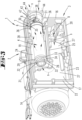
- eine ölgeschmierte Drehschieber-Vakuumpumpe in perspektivischer Darstellung;
- Fig. 2
- eine perspektivische Darstellung gemäß
Fig. 1 , jedoch partiell im Bereich einer Ölabscheideeinrichtung und eines Drehschieberraumes partiell geschnitten, weiter bei einem eine Montageöffnung freigebenden abgenommenen Deckel; - Fig. 3
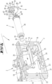
- eine weitere partiell geschnittene Perspektivdarstellung der Pumpe mit Blick auf die Ölabscheideeinrichtung;
- Fig. 4
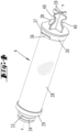
- ein Luftentölelement der Ölabscheideeinrichtung in perspektivischer Einzeldarstellung;
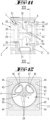
- Fig. 5
- eine der
Fig. 3 im Wesentlichen entsprechende perspektivische Schnittdarstellung mit einem zuordbaren Luftentölelement und einem zuordbaren Deckel; - Fig. 6
- eine der
Fig. 5 im Wesentlichen entsprechende Darstellung, jedoch nach Steckanordnung des Luftentölelementes in der Ölabscheideeinrichtung; - Fig. 7
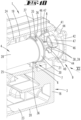
- die Herausvergrößerung des Bereiches VII in
Fig. 6 ; - Fig. 8
- eine Folgedarstellung zu
Fig. 7 , nach Verdrehen des Luftentölelementes um eine Längsachse zur Bajonetthalterung des Luftentölelementes in der Ölabscheideeinrichtung; - Fig. 9
- in perspektivischer Schnittdarstellung die Situation gemäß
Fig. 8 , mit dem zuordbaren Deckel; - Fig. 10
- eine der
Fig. 9 entsprechende Darstellung, jedoch nach Zuordnung und Festlegung des Deckels zum Verschluss der Montageöffnung; - Fig. 11
- die Ansicht gemäß Pfeil XI in
Fig. 10 ; - Fig. 12
- den Schnitt gemäß der Linie XII - XII in
Fig. 11 . - Dargestellt und beschrieben ist, zunächst mit Bezug zu den
Figuren 1 und2 , eine ölgeschmierte Drehschieber-Vakuumpumpe 1 mit einem Drehschieber-Aggregat 2 und einer Ölabscheideeinrichtung 3, in welcher ein Luftentölelement 4 aufgenommen ist. Das Luftentölelement 4 ist im Bereich einer mit Abstand zu einer Außenwand 21 der Ölabscheideeinrichtung 3 vorgesehenen Halterungswand 6 durch eine Bajonetthalterung 7 gehaltert. Die einen Zugriff auf das Luftentölelement 4 erlaubende Montageöffnung 8 in der Außenwand 21 ist im ordnungsgemäßen Betriebszustand der Drehschieber-Vakuumpumpe 1 durch einen gesonderten Deckel 9 verschlossen. - Das Drehschieber-Aggregat 2 kann ein Aggregatgehäuse aufweisen, in welchem ein Drehschieberraum 10 mit einem Drehschieberrotor 11 angeordnet ist.
- Der Drehschieberraum 10 kann in Art einer zylindrischen Bohrung in dem Aggregatgehäuse ausgebildet sein. Dabei weist der Drehschieberraum 10 eine Längserstreckung auf, die sich an der Bohrungsachse des Drehschieberraumes 10 orientieren kann.
- Der bevorzugt zylinderförmige Drehschieberrotor 11 ist gegenüber dem Drehschieberraum 10 exzentrisch angeordnet. Entsprechend verläuft eine Rotorachse parallel jedoch versetzt zur Raumachse des Drehschieberraumes 10.
- Weiter kann der Drehschieberrotor 11 mehrere, in dem Ausführungsbeispiel drei, Schieber 12 aufweisen. Diese können mit Bezug auf einen Querschnitt gemäß der Darstellung in
Figur 2 in etwa radial ausgerichteten Schlitzen 13 des Drehschieberrotors 11 schiebebeweglich angeordnet sein. Die Schieber 12 werden durch die Rotation des Drehschieberrotors 11 zufolge Fliehkraft gegen die den Drehschieberraum 10 begrenzende Wandung gedrückt. - Im Betrieb der Vakuumpumpe 1 dreht sich der Drehschieberrotor 11 radial versetzt zur Mittelachse des Drehschieberraumes 10, dies zufolge Antrieb über einen auf die Rotorwelle drehend einwirkenden Motor, insbesondere Elektromotor 14. Hierdurch ergeben sich, getrennt durch die radial verschieblich angeordneten Schieber 12, geschlossene Kammern 15, deren Größe sich während einer Umdrehung des Drehschieberrotors 11 ändert.
- Über die Größenänderung der Kammern 15 im Betrieb der Vakuumpumpe 1 ergeben sich Druckdifferenzen zwischen den einzelnen Kammern 15 und somit zwischen der Einlassseite E und der Auslassseite A des so gebildeten Gebläses. Die Auslassseite A kann sich, wie auch bevorzugt, in einem nicht näher dargestellten Durchtritt in die Ölabscheideeinrichtung 3 ergeben.
- Ölgeschmierte Drehschieber-Aggregate 2 zeichnen sich dadurch aus, dass bei diesen Öl in den Drehschieberraum 10 eingeleitet wird. Durch dieses Öl werden Spalte zwischen den verschiedenen Komponenten, insbesondere zwischen den Schiebern 12 und der Wandung des Drehschieberraumes 10 zugesetzt. So wird der Gasaustausch zwischen den verschiedenen Kammern 15 behindert. Auf diese Weise werden im Betrieb höhere Vakua erzielt als dies bei trockenlaufenden Drehschieberpumpen möglich ist.
- Das Öl wird bauartbedingt zusammen mit dem geförderten Gas aus der letzten Kammer 15 des Drehschieber-Aggregats 2 herausgefördert und tritt an der Auslassseite A als Öl-Gas-Gemisch in die Ölabscheideeinrichtung 3 ein.
- Das Öl läuft in einem Kreisprozess durch die Vakuumpumpe 1. In der Ölabscheideeinrichtung 3 wird eine Trennung von Öl und Gas erreicht.
- Die Ölabscheideeinrichtung 3 kann mit dem Drehschieber-Aggregat 2 verbunden sein, so dass sich gegebenenfalls eine Einheit bildet, bestehend aus Drehschieber-Aggregat 2, Ölabscheideeinrichtung 3 und Elektromotor 14.
- Die Ölabscheideeinrichtung 3, die darüber hinaus auch um eine Öl-Wiederaufbereitungseinrichtung ergänzt sein kann, weist bevorzugt ein Ölabscheidergehäuse 16 auf, mit Seitenwänden 17,18, einer Deckenwand 19, einer Bodenwand 20 sowie stirnseitigen Außenwänden 21, 22. Dabei können sich, gemäß der dargestellten Ausführungsform, die Außenwände 21, 22 quer gerichtet zu der Rotorachse im Drehschieber-Aggregat 2 erstrecken, wobei die Außenwand 21 gemäß dem dargestellten Ausführungsbeispiel der dem Elektromotor 14 abgewandten Seite zugeordnet sein kann.
- Die Ölabscheideeinrichtung 3 kann eine bevorzugt integral ausgebildete Kammerung aufweisen. Mit Bezug auf einen wie auch in den Zeichnungen dargestellten Aufstellzustand ergeben sich hinsichtlich der Schwerkraft eine untere Kammer 23 und eine obere Kammer 24. Die Trennung der Kammern 23 und 24 ist erreicht durch einen mit Bezug auf einen Querschnitt gemäß
Figur 3 quer zu den Seitenwänden 17, 18 verlaufenden Trennboden 25. - Die obere Kammer 24 dient im Wesentlichen zur Aufnahme des Luftentölelementes 4, kann sich hierbei, wie auch bevorzugt, im Wesentlichen gleichgerichtet zur der Rotorachse erstrecken. Es kann sich dabei eine in Längserstreckungsrichtung der oberen Kammer 24 jeweils endseitige Begrenzung durch Halterungswände 6, 26 ergeben.
- Das Öl-/Gasgemisch tritt im Betrieb der Vakuumpumpe 1 aus dem Drehschieber-Aggregat 2 über eine nicht dargestellte Durchtrittsöffnung im Bereich der Seitenwand 17 in die Ölabscheideeinrichtung 3 ein.
- Dabei kann zunächst eine Grobabscheidung von großen Öltropfen durch einen Schwerkraft- und/oder Prallabscheider erfolgen.
- Der sich unterhalb der Auslassseite A in dem Ölabscheidergehäuse 16 ergebende Gehäuseabschnitt 27 kann in Art einer Ölwanne dienen, in welcher sich ein Ölsumpf sammelt. Es kann so in der unteren Kammer 23 ein Öl-Sammelbehälter ausgeformt sein.
- Weiter formt die untere Kammer 23 einen Strömungsweg mit einer an der Längsausrichtung des Gehäuses 16 orientierten Strömung s. Diese Strömung s ist in Richtung auf die rückwärtige Außenwand 22 im Wesentlichen gerichtet, in welchem Bereich der hinteren Außenwand 22 eine Umlenkung der Strömung s zum Eintritt in die obere Kammer 24 sich einstellt.
- Das in der oberen Kammer 24 aufgenommene Luftentölelement 4 weist ein Filterelement 28 auf, insbesondere in Form einer Feinabscheideeinrichtung.
- Das Filterelement 28 kann dabei, wie beispielsweise in der Einzeldarstellung gemäß
Figur 4 gezeigt, eine röhrenförmige Filtermatte aufweisen, deren Röhrenachse gleichgerichtet sein kann zu der Rotorachse des Drehschieberrotors 11. So kann das Filterelement 28 und somit das gesamt Luftentölelement 4 im Wesentlichen in Längsrichtung des Ölabscheidergehäuses 16 orientiert angeordnet sein. - Das aus der unteren Kammer 23 in die obere Kammer 24 umgelenkte Öl-/Gasgemisch wird gezielt durch das Luftentölelement 4 geleitet, wobei sich vor und hinter dem Luftentölelement 4 ein Druckunterschied sich ergeben kann, der in Abhängigkeit vom Förderdruck des Drehschieber-Aggregats 2 bis zu 400 mbar betragen kann.
- Wie weiter beispielsweise aus
Figur 2 ersichtlich, erfolgt eine zentrale axiale Anströmung des Luftentölelementes 4 bzw. des Filterelementes 28, wobei unter Durchsatz des Filterelementes 28 nach radial außen das gereinigte Gas durch einen zwischen Filterelement 28 und der Kammerwandung der oberen Kammer 24 verbleibenden Ringraum und unter Durchtritt bzw. Umströmung der Halterungswand 6 nach außen aus dem Ölabscheidergehäuse 16 treten kann. - Die dabei in dem Filterelement 28 abgeschiedenen Öltropfen werden in den vorbeschriebenen Ölsumpf zurückgeführt.
- Das Filterelement 28 des Luftentölelementes 4 ist jeweils axial endseitig gefasst durch einen Steckring 29 im Bereich des distalen Endes und einem Flanschteil 30 im Bereich des proximalen Endes.
- Der Steckring 29 dient dabei bevorzugt zur abdichtenden Steckverbindung des Luftentölelementes 4 im Bereich der hinteren Halterungswand 26.
- Die hintere Halterungswand 26 weist eine zentrale Öffnung 31 auf, die umfasst ist von einem Kragen 32. In diese Öffnung 31 ist ein durchmesserreduzierter Abschnitt 33 des Steckrings 29 einsteckbar, wozu das Luftentölelement 4 in der oberen Kammer 24 einliegend bevorzugt in Längserstreckung des Luftentölelementes 4 in Richtung auf die Öffnung 31 verlagert wird.
- Dabei ergibt sich eine Abdichtung zwischen dem Abschnitt 33 und dem Kragen 32 der Öffnung 31, insbesondere zufolge Anordnung beispielsweise eines an dem Abschnitt 33 gehalterten umlaufenden Dichtungsrings 34. Dieser beispielsweise als O-Ring ausgebildete Dichtungsring 34 bietet die Möglichkeit einer radialen Abdichtung bei möglicher axialer Verschiebbarkeit.
- Im Bereich des zu dem Steckring 29 in Achsrichtung beabstandet vorgesehenen Flanschteils 30 erfährt das Luftentölelement 4 eine Abstützung und Halterung im Bereich der Halterungswand 6. Diese Halterungswand 6 ist im Wesentlichen in Achsrichtung des Luftentölelementes 4 zu der zugewandten Außenwand 21 in Richtung auf das Gehäuseinnere beabstandet.
- Das Flanschteil 30 ist dabei im Bereich einer in der Halterungswand 6 vorgesehenen Durchbrechung 35 abgestützt.
- Zur axialen Fixierung des Luftentölelementes 4 sind wandungsaußenseitig, bevorzugt mit Bezug auf die Elementachse x diametral gegenüberliegend, Bajonettlaschen 36 angeformt, die im Zuge einer Drehverlagerung des Luftentölelementes 4 um die Elementachse x mit ausgebildeten Steuerschrägen 37 in Wirkung treten mit der Halterungswand 6. Es ist hierdurch eine Bajonetthalterung des Luftentölelementes 4 in der oberen Kammer 24 erreichbar, wobei im Zuge des Erreichens der Bajonett-Halterungsstellung gemäß
Figur 8 zugleich auch eine axiale Verlagerung des Luftentölelementes 4 und somit auch des Abschnittes 33 mit dessen Dichtungsring 34 in die Dichtstellung erreicht wird. In der Bajonett-Halterungsstellung ist das Luftentölelement zischen den Halterungswänden 6 und 26 axial gesichert. - Die Drehverlagerung des Luftentölelementes 4 zur Erlangung der Halterungsstellung gemäß
Figur 8 kann unter Nutzung eines Handhabungsfortsatzes 38 des Luftentölelementes 4 erreicht werden. Dieser Handhabungsfortsatz 38 kann an dem Flanschteil 30 auf dessen dem Filterelement 38 abgewandten Bereich ausgebildet sein, kann sich dabei bevorzugt in der üblichen Nutzungsstellung des Luftentölelementes 4 im Wesentlichen zwischen der Halterungswand 6 und der zugewandten Außenwand 21 innerhalb des Ölabscheidergehäuses 16 erstrecken. - Der Handhabungsfortsatz 38 kann, wie auch dargestellt, aus zwei kreuzförmig zueinander angeordneten Plattenteilen 39 bestehen. Hierbei ergibt sich eine Kreuzform der Plattenteile 39 mit Bezug auf eine Projektion entlang der Elementachse x auf eine Querebene zur Elementachse x.
- Die Plattenteile 39 können zur Bildung des Handhabungsfortsatzes 38 einstückig und/oder materialeinheitlich mit dem Flanschteil 30 ausgebildet sein.
- Jedes Plattenteil 39 kann eine mit Bezug auf die Elementachse x nach radial außen randoffene Greifausnehmung 40 aufweisen.
- Bevorzugt konzentrisch zu der Elementachse x ist in der zugewandten Außenwand 21 des Ölabscheidergehäuses 16 die Montageöffnung 8 ausgebildet. Durch diese Montageöffnung 8 ist der Zugriff auf den Handhabungsfortsatz 38 des Luftentölelementes 4 ermöglicht, so insbesondere zum Einsetzen oder zum Entfernen des Luftentölelementes 4 durch die Montageöffnung 8.
- Der zum Verschluss der Montageöffnung 8 dienende Deckel 9 weist zunächst einen gegebenenfalls an die Öffnungskontur der Montageöffnung 8 angepassten Verschlussstutzen 41 auf. An diesem kann ein Befestigungskragen 42 angeformt sein.
- Während der Verschlussstutzen 41 einen quer zur Elementachse x betrachteten kreisrunden Grundriss aufweisen kann, kann der Befestigungskragen 42 insgesamt eine im Wesentlichen quadratische Grundrissfläche aufspannen, derart, dass insbesondere die Eckbereiche des Befestigungskragens 42 radial über den Verschlussstutzen 41 abstehen. In diesen Eckbereichen können Durchgangsbohrungen 43 vorgesehen sein, zum Durchsatz von Schrauben 44. Mittels dieser Schrauben 44 ist eine Schraubbefestigung des Deckels 9 außenseitig an der Außenwand 21 ermöglicht, wozu die Außenwand 21 entsprechende Gewindebohrungen 45 aufweisen kann.
- Weiter ist der Deckel 9 in dem dargestellten Ausführungsbeispiel mit zwei Durchgangsöffnungen 46 versehen, zum Austritt des gereinigten Gases. Diese Durchgangsöffnungen 46 können sich im Wesentlichen in Erstreckungsrichtung der Elementachse x erstrecken, wobei weiter diese Durchgangsöffnungen 46 deckelinnenseitig, d. h. dem Befestigungskragen 42 abgewandt und in der Zuordnungsstellung dem Filterelement 28 zugewandt, jeweils einen Wandungsfortsatz 47 aufweisen können. Diese Wandungsfortsätze 47 können eine axiale Verlängerung der die Durchgangsöffnung 46 auch im Bereich des Verschlussstutzens 41 umfassenden Wandung bilden.
- Die Länge der Wandungsfortsätze 47 in Achsrichtung betrachtet, insbesondere die über die zum Filterelement 28 hinweisende Stirnfläche des Verschlussstutzens 41 frei abragende Länge der Wandungsfortsätze 47, kann weiter so gewählt sein, dass in der betriebsbereiten Aufnahmestellung des Luftentölelementes 4 und der Verschlussstellung der Montageöffnung 8 die Wandungsfortsätze 47 in einer Projektion quergerichtet zur Elementachse x in zumindest teilweiser Überdeckung liegend zu den Plattenteilen 29 bzw. zu dem Handhabungsfortsatz 38 des Luftentölelementes 4 vorgesehen sein können.
- Hierbei können die Wandungsfortsätze 47 jeweils eine solche Grundrissfläche aufspannen, darüber hinaus zueinander in Umfangsrichtung beabstandet sein, dass die Wandungsfortsätze 47 in der Montageöffnungs-/Verschlussstellung zwischen zwei in Umfangsrichtung aufeinanderfolgende Plattenteile 39 greifen (vgl.
Figuren 11 und 12 ). Hierdurch ist eine Drehsicherung des Luftentölelementes 4 bzw. des Filterelementes 28 gegeben, durch blockierenden Eingriff zumindest eines Wandungsfortsatzes 47 in einen Zwischenraum zwischen zwei in Umfangsrichtung aufeinanderfolgenden Plattenteilen 29. - Bevorzugt ist der ordnungsgemäße Verschluss der Montageöffnung 8 durch den Deckel 9 nur in der dargestellten Bajonett-Verschlussstellung des Luftentölelementes 4 möglich. Ist die Bajonett-Halterungsendstellung des Luftentölelementes 4 nicht erreicht, kann gemäß einer bevorzugten Ausgestaltung der Deckel 9 nicht ordnungsgemäß angesetzt und mit dem Ölabscheidergehäuse 16 bzw. mit der Außenwand 21 verschraubt werden. Die Wandungsfortsätze 47 treten in einem solchen Fall störend gegen Abschnitte der Plattenteile 39, so dass der Deckel 9 nicht seine ordnungsgemäße Anlagestellung an der Außenwand 21 erreichen kann.
Liste der Bezugszeichen 1 Drehschieber-Vakuumpumpe 28 Filterelement 2 Drehschieber-Aggregat 29 Steckring 3 Ölabscheideeinrichtung 30 Flanschteil 4 Luftentölelement 31 Öffnung 5 ----------- 32 Kragen 6 Halterungswand 33 Abschnitt 7 Bajonetthalterung 34 Dichtungsring 8 Montageöffnung 35 Durchbrechung 9 Deckel 36 Bajonettlasche 10 Drehschieberraum 37 Steuerschräge 11 Drehschieberrotor 38 Handhabungsfortsatz 12 Schieber 39 Plattenteil 13 Schlitz 40 Greifausnehmung 14 Elektromotor 41 Verschlussstutzen 15 Kammer 42 Befestigungskragen 16 Ölabscheidergehäuse 43 Durchgangsbohrung 17 Seitenwand 44 Schraube 18 Seitenwand 45 Gewindebohrung 19 Deckenwand 46 Durchgangsöffnung 20 Bodenwand 47 Wandungsfortsatz 21 Außenwand 22 Außenwand s Strömung 23 untere Kammer x Elementachse 24 obere Kammer 25 Trennboden A Auslassseite 26 Halterungswand E Einlassseite 27 Gehäuseabschnitt
Claims (9)
- Ölgeschmierte Drehschieber-Vakuumpumpe (1) mit einem Drehschieber-Aggregat (2), aufweisend einen Drehschieberraum (10) und einen Drehschieberrotor (11), und mit einer Ölabscheideeinrichtung (3), wobei in der Ölabscheideeinrichtung (3) eine Trennung von Gas und Öl durch ein Luftentölelement (4) erfolgt, wobei das Luftentölelement (4) ein Filterelement (28) aufweist, das an einem gehäuseseitig steckverbindbaren Ende einen Steckring (29) aufweist, der zur radialen Abdichtung und axialen Verschiebbarkeit in einer zugeordneten Gehäuseaufnahme ausgebildet ist, und das Filterelement (28) zugewandt dem der Außenwand (21) zugeordneten Ende eine Ausformung zur Bajonetthalterung aufweist, dadurch gekennzeichnet, dass zur Zusammenwirkung mit der Ausformung des Filterelementes (28) und zur Bildung der Bajonetthalterung eine mit Abstand zu der Außenwand (21) des Gehäuses (16) verlaufende Halterungswand (6) des Gehäuses (16) ausgebildet ist, dass ein gesonderter Deckel (9) vorgesehen ist, der eine dem Filterelement (28) zugeordnete Montagöffnung (8) in der Außenwand (21) des Gehäuses (16) verschließen lässt und dass der Deckel (9) mit dem Filterelement (28) zur Drehsicherung des Filterelementes (28) formschlüssig zusammenwirkt.
- Drehschieber-Vakuumpumpe (1) nach Anspruch 1, dadurch gekennzeichnet, dass der Deckel (9) zur Steckhalterung in dem Gehäuse (16) ausgebildet ist.
- Drehschieber-Vakuumpumpe (1) nach einem der vorherigen Ansprüche, dadurch gekennzeichnet, dass der Deckel (9) mittels Schrauben (44) an dem Gehäuse (16) festlegbar ist.
- Drehschieber-Vakuumpumpe (1) nach einem der vorherigen Ansprüche, dadurch gekennzeichnet, dass das Filterelement (28) zugeordnet der Außenwand (21) einen Handhabungsfortsatz (38) aufweist, der von einem Flanschteil (30) des Filterelementes (28) zur Außenwand (21) des Gehäuses (16) hin absteht.
- Drehschieber-Vakuumpumpe (1) nach Anspruch 4, dadurch gekennzeichnet, dass der Handhabungsfortsatz (38) knaufartig gebildet ist.
- Drehschieber-Vakuumpumpe (1) nach Anspruch 4, dadurch gekennzeichnet, dass der Handhabungsfortsatz (38) aus einem oder mehreren Plattenteilen (39) besteht.
- Drehschieber-Vakuumpumpe (1) nach Anspruch 6, dadurch gekennzeichnet, dass der Handhabungsfortsatz (38) aus zwei kreuzförmig angeordneten Plattenteilen (39) besteht.
- Drehschieber-Vakuumpumpe (1) nach einem der vorherigen Ansprüche, dadurch gekennzeichnet, dass der Deckel (9) ein oder mehrere Durchgangsöffnungen (46) zum Austritt von gereinigtem Gas aufweist.
- Drehschieber-Vakuumpumpe (1) nach Anspruch 8, dadurch gekennzeichnet, dass eine Durchgangsöffnung (46) deckelinnenseitig zugewandt dem Filterelement (28) einen Wandungsfortsatz (47) aufweist, der in Formschlussverbindung zu dem Handhabungsfortsatz (38) des Filterelementes (28) treten kann.
Applications Claiming Priority (2)
| Application Number | Priority Date | Filing Date | Title |
|---|---|---|---|
| DE102019105695.0A DE102019105695A1 (de) | 2019-03-06 | 2019-03-06 | Ölgeschmierte Drehschieber-Vakuumpumpe |
| PCT/EP2020/055704 WO2020178344A1 (de) | 2019-03-06 | 2020-03-04 | Ölgeschmierte drehschieber-vakuumpumpe |
Publications (2)
| Publication Number | Publication Date |
|---|---|
| EP3935282A1 EP3935282A1 (de) | 2022-01-12 |
| EP3935282B1 true EP3935282B1 (de) | 2023-04-26 |
Family
ID=69846397
Family Applications (1)
| Application Number | Title | Priority Date | Filing Date |
|---|---|---|---|
| EP20712450.4A Active EP3935282B1 (de) | 2019-03-06 | 2020-03-04 | Ölgeschmierte drehschieber-vakuumpumpe |
Country Status (5)
| Country | Link |
|---|---|
| US (1) | US11767845B2 (de) |
| EP (1) | EP3935282B1 (de) |
| CN (1) | CN113508229B (de) |
| DE (1) | DE102019105695A1 (de) |
| WO (1) | WO2020178344A1 (de) |
Families Citing this family (6)
| Publication number | Priority date | Publication date | Assignee | Title |
|---|---|---|---|---|
| DE102020207510A1 (de) * | 2020-06-17 | 2021-12-23 | Brose Fahrzeugteile SE & Co. Kommanditgesellschaft, Würzburg | Verdichtermodul sowie elektromotorischer Kältemittelverdichter |
| WO2023227765A1 (en) * | 2022-05-27 | 2023-11-30 | Leybold France Sas | A lubricant sealed pump system, a lubricant reservoir and method of manufacture |
| GB2619102A (en) * | 2022-05-27 | 2023-11-29 | Leybold France S A S | A lubricant sealed pump system, inner compartment for a lubricant reservoir and method of manufacture |
| KR20250111151A (ko) * | 2022-11-17 | 2025-07-22 | 부슈 프로둑찌온스 게엠베하 | 로터리 베인 진공 펌프용 개선된 가스 탈유 요소 |
| GB2624944A (en) * | 2022-11-30 | 2024-06-05 | Leybold France Sas | Lubricant sealed pump, removable filter and compartment for retaining filter |
| EP4459127A1 (de) * | 2023-05-02 | 2024-11-06 | Leybold France SAS | Schmiermittelgedichtete pumpe |
Family Cites Families (9)
| Publication number | Priority date | Publication date | Assignee | Title |
|---|---|---|---|---|
| DE20103261U1 (de) | 2001-02-23 | 2001-06-07 | Werner Rietschle GmbH + Co. KG, 79650 Schopfheim | Ölabscheider für ölüberflutete Pumpen |
| PL2117671T3 (pl) | 2006-11-27 | 2013-08-30 | Ateliers Busch S A | Urządzenie do montażu filtrów |
| CN201258857Y (zh) * | 2008-03-14 | 2009-06-17 | 厄利孔莱博尔德真空技术有限责任公司 | 用于抽取易燃气体的旋转叶片真空泵 |
| PL2986821T3 (pl) * | 2013-04-19 | 2021-07-26 | Ateliers Busch S.A. | Obrotowa łopatkowa pompa próżniowa |
| DE102015107721A1 (de) | 2015-05-18 | 2016-11-24 | Gebr. Becker Gmbh | Ölgeschmierte Drehschieber-Vakuumpumpe |
| WO2017092795A1 (fr) * | 2015-12-01 | 2017-06-08 | Ateliers Busch S.A. | Pompe a vide avec element filtrant |
| DE102016112570A1 (de) | 2016-07-08 | 2018-01-11 | Gebr. Becker Gmbh | Ölgeschmierte Drehschieber-Vakuumpumpe |
| WO2019010671A1 (en) * | 2017-07-13 | 2019-01-17 | Mann+Hummel Gmbh | SEPARATION DEVICE AND OIL SEPARATION AIR FILTER ASSEMBLY COMPRISING SUCH A SEPARATION DEVICE AND METHOD OF SEPARATING FLUID FROM A GAS FLOW FROM A CONNECTING DEVICE |
| CN108661905A (zh) * | 2018-06-27 | 2018-10-16 | 宁波爱发科真空技术有限公司 | 一种具有辅助排气机构的真空泵 |
-
2019
- 2019-03-06 DE DE102019105695.0A patent/DE102019105695A1/de not_active Withdrawn
-
2020
- 2020-03-04 WO PCT/EP2020/055704 patent/WO2020178344A1/de not_active Ceased
- 2020-03-04 US US17/428,733 patent/US11767845B2/en active Active
- 2020-03-04 EP EP20712450.4A patent/EP3935282B1/de active Active
- 2020-03-04 CN CN202080017372.9A patent/CN113508229B/zh active Active
Also Published As
| Publication number | Publication date |
|---|---|
| US20220099093A1 (en) | 2022-03-31 |
| CN113508229A (zh) | 2021-10-15 |
| US11767845B2 (en) | 2023-09-26 |
| CN113508229B (zh) | 2024-03-26 |
| DE102019105695A1 (de) | 2020-09-10 |
| WO2020178344A1 (de) | 2020-09-10 |
| EP3935282A1 (de) | 2022-01-12 |
Similar Documents
| Publication | Publication Date | Title |
|---|---|---|
| DE102019105695A1 (de) | Ölgeschmierte Drehschieber-Vakuumpumpe | |
| EP3298241B1 (de) | Ölgeschmierte drehschieber-vakuumpumpe mit ölabscheide- und wiederaufbereitungseinrichtung | |
| EP3482078B1 (de) | Ölgeschmierte drehschieber-vakuumpumpe | |
| EP2535099A2 (de) | Luftfilterelement, Filtergehäuse und Filteranordnung | |
| DE102006038700B4 (de) | Vorrichtung zur Abscheidung von Flüssigkeiten aus Gasen | |
| DE202014004864U1 (de) | Eine Luft-Flüssigkeit-Abscheideeinrichtung und ein Reiniger mit der Luft-Flüssigkeit-Abscheideeinrichtung für harte Oberflächen | |
| WO2017129417A1 (de) | Gehäuse, fluidauslass-dichtungsteil, gehäusedeckel und verbindungsteil einer einrichtung zur abscheidung wenigstens eines fluids aus gas und einrichtung und vorrichtung zur abscheidung eines fluids | |
| DE102018105588B4 (de) | Zentrifugalabscheider zum Abscheiden von Öltröpfchen aus dem Kurbelgehäuseentlüftungsgas einer Brennkraftmaschine | |
| EP4026601B1 (de) | Filtereinsatz zum einbau in einen flüssigkeitsabscheider, flüssigeitsabscheider, verfahren zum bereitstellen des vorgenannten filtereinsatzes sowie verwendung des filtereinsatzes in einem flüssigkeitsabscheider | |
| EP4048428B1 (de) | Abscheidevorrichtung zur abscheidung von flüssigkeit aus gas, insbesondere luft, und abscheidesystem einer maschine | |
| EP3924605B1 (de) | Drehkolbenpumpe mit filter | |
| WO2020064204A1 (de) | Luftentöleinsatz einer luftentölvorrichtung und luftentölvorrichtung | |
| DE102004005500A1 (de) | Staubsauger | |
| DE202009016309U1 (de) | Einrichtung zur Trennung eines Gas-Flüssigkeit-Gemischs | |
| DE60313841T2 (de) | Schraubenverdichter mit in-line Öl-Abscheider | |
| DE102013020533A1 (de) | Verdichter | |
| WO2019024991A1 (de) | Gehäuse, fluidauslass-dichtungsteil, gehäusedeckel und verbindungsteil einer einrichtung zur abscheidung wenigstens eines fluids aus gas und einrichtung und vorrichtung zur abscheidung eines fluids | |
| DE102010027785B4 (de) | Ölnebelabscheider mit einem Gehäuse mit abnehmbarem Deckel | |
| EP3051136B1 (de) | Vakuumpumpe | |
| EP4619643A1 (de) | Verbessertes gasentölelement für drehschieber-vakuumpumpen | |
| DE102023133188B4 (de) | Filtereinsatz für einen Flüssigkeitsabscheider, Flüssigkeitsabscheider und Verwendung eines Filtereinsatzes in einem solchen | |
| EP3329824B1 (de) | Filtervorrichtung zum filtern eines fluids, verfahren zum filtern eines fluids und staubsauger | |
| EP1329252B1 (de) | Vorrichtung zur Flüssigkeitsabscheidung und Filterung von komprimierten Gasen | |
| DE102013020536A1 (de) | Verdichter | |
| WO2017134018A1 (de) | Abscheidevorrichtung |
Legal Events
| Date | Code | Title | Description |
|---|---|---|---|
| STAA | Information on the status of an ep patent application or granted ep patent |
Free format text: STATUS: UNKNOWN |
|
| STAA | Information on the status of an ep patent application or granted ep patent |
Free format text: STATUS: THE INTERNATIONAL PUBLICATION HAS BEEN MADE |
|
| PUAI | Public reference made under article 153(3) epc to a published international application that has entered the european phase |
Free format text: ORIGINAL CODE: 0009012 |
|
| STAA | Information on the status of an ep patent application or granted ep patent |
Free format text: STATUS: REQUEST FOR EXAMINATION WAS MADE |
|
| 17P | Request for examination filed |
Effective date: 20211005 |
|
| AK | Designated contracting states |
Kind code of ref document: A1 Designated state(s): AL AT BE BG CH CY CZ DE DK EE ES FI FR GB GR HR HU IE IS IT LI LT LU LV MC MK MT NL NO PL PT RO RS SE SI SK SM TR |
|
| DAV | Request for validation of the european patent (deleted) | ||
| DAX | Request for extension of the european patent (deleted) | ||
| REG | Reference to a national code |
Ref country code: DE Ref legal event code: R079 Ref document number: 502020003090 Country of ref document: DE Free format text: PREVIOUS MAIN CLASS: F04C0018344000 Ipc: F04C0025020000 |
|
| GRAP | Despatch of communication of intention to grant a patent |
Free format text: ORIGINAL CODE: EPIDOSNIGR1 |
|
| STAA | Information on the status of an ep patent application or granted ep patent |
Free format text: STATUS: GRANT OF PATENT IS INTENDED |
|
| RIC1 | Information provided on ipc code assigned before grant |
Ipc: F04C 29/02 20060101ALI20221013BHEP Ipc: F04C 18/344 20060101ALI20221013BHEP Ipc: F04C 29/12 20060101ALI20221013BHEP Ipc: F04C 25/02 20060101AFI20221013BHEP |
|
| INTG | Intention to grant announced |
Effective date: 20221114 |
|
| GRAS | Grant fee paid |
Free format text: ORIGINAL CODE: EPIDOSNIGR3 |
|
| GRAA | (expected) grant |
Free format text: ORIGINAL CODE: 0009210 |
|
| STAA | Information on the status of an ep patent application or granted ep patent |
Free format text: STATUS: THE PATENT HAS BEEN GRANTED |
|
| AK | Designated contracting states |
Kind code of ref document: B1 Designated state(s): AL AT BE BG CH CY CZ DE DK EE ES FI FR GB GR HR HU IE IS IT LI LT LU LV MC MK MT NL NO PL PT RO RS SE SI SK SM TR |
|
| REG | Reference to a national code |
Ref country code: GB Ref legal event code: FG4D Free format text: NOT ENGLISH |
|
| REG | Reference to a national code |
Ref country code: CH Ref legal event code: EP |
|
| REG | Reference to a national code |
Ref country code: DE Ref legal event code: R096 Ref document number: 502020003090 Country of ref document: DE |
|
| REG | Reference to a national code |
Ref country code: AT Ref legal event code: REF Ref document number: 1563003 Country of ref document: AT Kind code of ref document: T Effective date: 20230515 |
|
| REG | Reference to a national code |
Ref country code: IE Ref legal event code: FG4D Free format text: LANGUAGE OF EP DOCUMENT: GERMAN |
|
| P01 | Opt-out of the competence of the unified patent court (upc) registered |
Effective date: 20230523 |
|
| REG | Reference to a national code |
Ref country code: LT Ref legal event code: MG9D |
|
| REG | Reference to a national code |
Ref country code: NL Ref legal event code: MP Effective date: 20230426 |
|
| PG25 | Lapsed in a contracting state [announced via postgrant information from national office to epo] |
Ref country code: NL Free format text: LAPSE BECAUSE OF FAILURE TO SUBMIT A TRANSLATION OF THE DESCRIPTION OR TO PAY THE FEE WITHIN THE PRESCRIBED TIME-LIMIT Effective date: 20230426 |
|
| PG25 | Lapsed in a contracting state [announced via postgrant information from national office to epo] |
Ref country code: SE Free format text: LAPSE BECAUSE OF FAILURE TO SUBMIT A TRANSLATION OF THE DESCRIPTION OR TO PAY THE FEE WITHIN THE PRESCRIBED TIME-LIMIT Effective date: 20230426 Ref country code: PT Free format text: LAPSE BECAUSE OF FAILURE TO SUBMIT A TRANSLATION OF THE DESCRIPTION OR TO PAY THE FEE WITHIN THE PRESCRIBED TIME-LIMIT Effective date: 20230828 Ref country code: NO Free format text: LAPSE BECAUSE OF FAILURE TO SUBMIT A TRANSLATION OF THE DESCRIPTION OR TO PAY THE FEE WITHIN THE PRESCRIBED TIME-LIMIT Effective date: 20230726 Ref country code: ES Free format text: LAPSE BECAUSE OF FAILURE TO SUBMIT A TRANSLATION OF THE DESCRIPTION OR TO PAY THE FEE WITHIN THE PRESCRIBED TIME-LIMIT Effective date: 20230426 |
|
| PG25 | Lapsed in a contracting state [announced via postgrant information from national office to epo] |
Ref country code: RS Free format text: LAPSE BECAUSE OF FAILURE TO SUBMIT A TRANSLATION OF THE DESCRIPTION OR TO PAY THE FEE WITHIN THE PRESCRIBED TIME-LIMIT Effective date: 20230426 Ref country code: PL Free format text: LAPSE BECAUSE OF FAILURE TO SUBMIT A TRANSLATION OF THE DESCRIPTION OR TO PAY THE FEE WITHIN THE PRESCRIBED TIME-LIMIT Effective date: 20230426 Ref country code: LV Free format text: LAPSE BECAUSE OF FAILURE TO SUBMIT A TRANSLATION OF THE DESCRIPTION OR TO PAY THE FEE WITHIN THE PRESCRIBED TIME-LIMIT Effective date: 20230426 Ref country code: LT Free format text: LAPSE BECAUSE OF FAILURE TO SUBMIT A TRANSLATION OF THE DESCRIPTION OR TO PAY THE FEE WITHIN THE PRESCRIBED TIME-LIMIT Effective date: 20230426 Ref country code: IS Free format text: LAPSE BECAUSE OF FAILURE TO SUBMIT A TRANSLATION OF THE DESCRIPTION OR TO PAY THE FEE WITHIN THE PRESCRIBED TIME-LIMIT Effective date: 20230826 Ref country code: HR Free format text: LAPSE BECAUSE OF FAILURE TO SUBMIT A TRANSLATION OF THE DESCRIPTION OR TO PAY THE FEE WITHIN THE PRESCRIBED TIME-LIMIT Effective date: 20230426 Ref country code: GR Free format text: LAPSE BECAUSE OF FAILURE TO SUBMIT A TRANSLATION OF THE DESCRIPTION OR TO PAY THE FEE WITHIN THE PRESCRIBED TIME-LIMIT Effective date: 20230727 |
|
| PG25 | Lapsed in a contracting state [announced via postgrant information from national office to epo] |
Ref country code: FI Free format text: LAPSE BECAUSE OF FAILURE TO SUBMIT A TRANSLATION OF THE DESCRIPTION OR TO PAY THE FEE WITHIN THE PRESCRIBED TIME-LIMIT Effective date: 20230426 |
|
| PG25 | Lapsed in a contracting state [announced via postgrant information from national office to epo] |
Ref country code: SK Free format text: LAPSE BECAUSE OF FAILURE TO SUBMIT A TRANSLATION OF THE DESCRIPTION OR TO PAY THE FEE WITHIN THE PRESCRIBED TIME-LIMIT Effective date: 20230426 |
|
| REG | Reference to a national code |
Ref country code: DE Ref legal event code: R097 Ref document number: 502020003090 Country of ref document: DE |
|
| PG25 | Lapsed in a contracting state [announced via postgrant information from national office to epo] |
Ref country code: SM Free format text: LAPSE BECAUSE OF FAILURE TO SUBMIT A TRANSLATION OF THE DESCRIPTION OR TO PAY THE FEE WITHIN THE PRESCRIBED TIME-LIMIT Effective date: 20230426 Ref country code: SK Free format text: LAPSE BECAUSE OF FAILURE TO SUBMIT A TRANSLATION OF THE DESCRIPTION OR TO PAY THE FEE WITHIN THE PRESCRIBED TIME-LIMIT Effective date: 20230426 Ref country code: RO Free format text: LAPSE BECAUSE OF FAILURE TO SUBMIT A TRANSLATION OF THE DESCRIPTION OR TO PAY THE FEE WITHIN THE PRESCRIBED TIME-LIMIT Effective date: 20230426 Ref country code: EE Free format text: LAPSE BECAUSE OF FAILURE TO SUBMIT A TRANSLATION OF THE DESCRIPTION OR TO PAY THE FEE WITHIN THE PRESCRIBED TIME-LIMIT Effective date: 20230426 Ref country code: DK Free format text: LAPSE BECAUSE OF FAILURE TO SUBMIT A TRANSLATION OF THE DESCRIPTION OR TO PAY THE FEE WITHIN THE PRESCRIBED TIME-LIMIT Effective date: 20230426 Ref country code: CZ Free format text: LAPSE BECAUSE OF FAILURE TO SUBMIT A TRANSLATION OF THE DESCRIPTION OR TO PAY THE FEE WITHIN THE PRESCRIBED TIME-LIMIT Effective date: 20230426 |
|
| PLBE | No opposition filed within time limit |
Free format text: ORIGINAL CODE: 0009261 |
|
| STAA | Information on the status of an ep patent application or granted ep patent |
Free format text: STATUS: NO OPPOSITION FILED WITHIN TIME LIMIT |
|
| 26N | No opposition filed |
Effective date: 20240129 |
|
| PG25 | Lapsed in a contracting state [announced via postgrant information from national office to epo] |
Ref country code: SI Free format text: LAPSE BECAUSE OF FAILURE TO SUBMIT A TRANSLATION OF THE DESCRIPTION OR TO PAY THE FEE WITHIN THE PRESCRIBED TIME-LIMIT Effective date: 20230426 |
|
| PG25 | Lapsed in a contracting state [announced via postgrant information from national office to epo] |
Ref country code: SI Free format text: LAPSE BECAUSE OF FAILURE TO SUBMIT A TRANSLATION OF THE DESCRIPTION OR TO PAY THE FEE WITHIN THE PRESCRIBED TIME-LIMIT Effective date: 20230426 |
|
| REG | Reference to a national code |
Ref country code: CH Ref legal event code: PL |
|
| PG25 | Lapsed in a contracting state [announced via postgrant information from national office to epo] |
Ref country code: BG Free format text: LAPSE BECAUSE OF FAILURE TO SUBMIT A TRANSLATION OF THE DESCRIPTION OR TO PAY THE FEE WITHIN THE PRESCRIBED TIME-LIMIT Effective date: 20230426 |
|
| PG25 | Lapsed in a contracting state [announced via postgrant information from national office to epo] |
Ref country code: LU Free format text: LAPSE BECAUSE OF NON-PAYMENT OF DUE FEES Effective date: 20240304 |
|
| PG25 | Lapsed in a contracting state [announced via postgrant information from national office to epo] |
Ref country code: MC Free format text: LAPSE BECAUSE OF FAILURE TO SUBMIT A TRANSLATION OF THE DESCRIPTION OR TO PAY THE FEE WITHIN THE PRESCRIBED TIME-LIMIT Effective date: 20230426 |
|
| GBPC | Gb: european patent ceased through non-payment of renewal fee |
Effective date: 20240304 |
|
| PG25 | Lapsed in a contracting state [announced via postgrant information from national office to epo] |
Ref country code: MC Free format text: LAPSE BECAUSE OF FAILURE TO SUBMIT A TRANSLATION OF THE DESCRIPTION OR TO PAY THE FEE WITHIN THE PRESCRIBED TIME-LIMIT Effective date: 20230426 Ref country code: LU Free format text: LAPSE BECAUSE OF NON-PAYMENT OF DUE FEES Effective date: 20240304 Ref country code: BG Free format text: LAPSE BECAUSE OF FAILURE TO SUBMIT A TRANSLATION OF THE DESCRIPTION OR TO PAY THE FEE WITHIN THE PRESCRIBED TIME-LIMIT Effective date: 20230426 |
|
| REG | Reference to a national code |
Ref country code: BE Ref legal event code: MM Effective date: 20240331 |
|
| PG25 | Lapsed in a contracting state [announced via postgrant information from national office to epo] |
Ref country code: BE Free format text: LAPSE BECAUSE OF NON-PAYMENT OF DUE FEES Effective date: 20240331 |
|
| PG25 | Lapsed in a contracting state [announced via postgrant information from national office to epo] |
Ref country code: GB Free format text: LAPSE BECAUSE OF NON-PAYMENT OF DUE FEES Effective date: 20240304 |
|
| PG25 | Lapsed in a contracting state [announced via postgrant information from national office to epo] |
Ref country code: IE Free format text: LAPSE BECAUSE OF NON-PAYMENT OF DUE FEES Effective date: 20240304 |
|
| PG25 | Lapsed in a contracting state [announced via postgrant information from national office to epo] |
Ref country code: IE Free format text: LAPSE BECAUSE OF NON-PAYMENT OF DUE FEES Effective date: 20240304 Ref country code: GB Free format text: LAPSE BECAUSE OF NON-PAYMENT OF DUE FEES Effective date: 20240304 Ref country code: BE Free format text: LAPSE BECAUSE OF NON-PAYMENT OF DUE FEES Effective date: 20240331 Ref country code: CH Free format text: LAPSE BECAUSE OF NON-PAYMENT OF DUE FEES Effective date: 20240331 |
|
| PGFP | Annual fee paid to national office [announced via postgrant information from national office to epo] |
Ref country code: AT Payment date: 20250417 Year of fee payment: 5 |
|
| PG25 | Lapsed in a contracting state [announced via postgrant information from national office to epo] |
Ref country code: CY Free format text: LAPSE BECAUSE OF FAILURE TO SUBMIT A TRANSLATION OF THE DESCRIPTION OR TO PAY THE FEE WITHIN THE PRESCRIBED TIME-LIMIT; INVALID AB INITIO Effective date: 20200304 |
|
| PG25 | Lapsed in a contracting state [announced via postgrant information from national office to epo] |
Ref country code: HU Free format text: LAPSE BECAUSE OF FAILURE TO SUBMIT A TRANSLATION OF THE DESCRIPTION OR TO PAY THE FEE WITHIN THE PRESCRIBED TIME-LIMIT; INVALID AB INITIO Effective date: 20200304 |
|
| PG25 | Lapsed in a contracting state [announced via postgrant information from national office to epo] |
Ref country code: TR Free format text: LAPSE BECAUSE OF FAILURE TO SUBMIT A TRANSLATION OF THE DESCRIPTION OR TO PAY THE FEE WITHIN THE PRESCRIBED TIME-LIMIT Effective date: 20230426 |
|
| PGFP | Annual fee paid to national office [announced via postgrant information from national office to epo] |
Ref country code: DE Payment date: 20260311 Year of fee payment: 7 |
|
| PGFP | Annual fee paid to national office [announced via postgrant information from national office to epo] |
Ref country code: IT Payment date: 20260324 Year of fee payment: 7 |
|
| PGFP | Annual fee paid to national office [announced via postgrant information from national office to epo] |
Ref country code: FR Payment date: 20260309 Year of fee payment: 7 |