EP3934539B1 - Verfahren und systeme zur erfassung von 3d-ultraschallbildern - Google Patents
Verfahren und systeme zur erfassung von 3d-ultraschallbildern Download PDFInfo
- Publication number
- EP3934539B1 EP3934539B1 EP20707470.9A EP20707470A EP3934539B1 EP 3934539 B1 EP3934539 B1 EP 3934539B1 EP 20707470 A EP20707470 A EP 20707470A EP 3934539 B1 EP3934539 B1 EP 3934539B1
- Authority
- EP
- European Patent Office
- Prior art keywords
- ultrasound
- additional
- ultrasound image
- image
- anatomical feature
- Prior art date
- Legal status (The legal status is an assumption and is not a legal conclusion. Google has not performed a legal analysis and makes no representation as to the accuracy of the status listed.)
- Active
Links
- 238000002604 ultrasonography Methods 0.000 title claims description 234
- 238000000034 method Methods 0.000 title claims description 53
- 239000002131 composite material Substances 0.000 title claims description 43
- 238000003384 imaging method Methods 0.000 claims description 46
- 230000033001 locomotion Effects 0.000 claims description 35
- 238000002156 mixing Methods 0.000 claims description 21
- 239000000523 sample Substances 0.000 claims description 21
- 238000012545 processing Methods 0.000 claims description 16
- 238000004422 calculation algorithm Methods 0.000 claims description 11
- 238000010801 machine learning Methods 0.000 claims description 9
- 238000004590 computer program Methods 0.000 claims description 7
- 230000009466 transformation Effects 0.000 claims description 5
- 239000011159 matrix material Substances 0.000 claims description 4
- 239000000203 mixture Substances 0.000 claims description 2
- 230000005540 biological transmission Effects 0.000 description 15
- 230000006870 function Effects 0.000 description 13
- 210000003484 anatomy Anatomy 0.000 description 8
- 238000012285 ultrasound imaging Methods 0.000 description 7
- 230000008569 process Effects 0.000 description 6
- 238000002592 echocardiography Methods 0.000 description 5
- 230000004913 activation Effects 0.000 description 4
- 238000001994 activation Methods 0.000 description 4
- 230000017531 blood circulation Effects 0.000 description 4
- 210000003754 fetus Anatomy 0.000 description 4
- 238000005259 measurement Methods 0.000 description 4
- 210000000056 organ Anatomy 0.000 description 4
- 238000011002 quantification Methods 0.000 description 4
- 230000011218 segmentation Effects 0.000 description 4
- 230000008901 benefit Effects 0.000 description 3
- 230000001419 dependent effect Effects 0.000 description 3
- 230000004927 fusion Effects 0.000 description 3
- 230000003213 activating effect Effects 0.000 description 2
- 238000013459 approach Methods 0.000 description 2
- 230000008859 change Effects 0.000 description 2
- 238000013135 deep learning Methods 0.000 description 2
- 230000001934 delay Effects 0.000 description 2
- 238000001514 detection method Methods 0.000 description 2
- 239000000463 material Substances 0.000 description 2
- 230000009467 reduction Effects 0.000 description 2
- 238000000926 separation method Methods 0.000 description 2
- 238000003860 storage Methods 0.000 description 2
- 239000011165 3D composite Substances 0.000 description 1
- 239000002033 PVDF binder Substances 0.000 description 1
- 238000005267 amalgamation Methods 0.000 description 1
- 210000004381 amniotic fluid Anatomy 0.000 description 1
- 210000001765 aortic valve Anatomy 0.000 description 1
- 238000003491 array Methods 0.000 description 1
- 238000013528 artificial neural network Methods 0.000 description 1
- 230000002457 bidirectional effect Effects 0.000 description 1
- 230000015572 biosynthetic process Effects 0.000 description 1
- 210000000601 blood cell Anatomy 0.000 description 1
- 210000004204 blood vessel Anatomy 0.000 description 1
- 230000003139 buffering effect Effects 0.000 description 1
- 230000000747 cardiac effect Effects 0.000 description 1
- 239000003086 colorant Substances 0.000 description 1
- 238000013329 compounding Methods 0.000 description 1
- 238000007796 conventional method Methods 0.000 description 1
- 238000012937 correction Methods 0.000 description 1
- 238000002059 diagnostic imaging Methods 0.000 description 1
- 238000009826 distribution Methods 0.000 description 1
- 230000000694 effects Effects 0.000 description 1
- 230000008030 elimination Effects 0.000 description 1
- 238000003379 elimination reaction Methods 0.000 description 1
- 230000001605 fetal effect Effects 0.000 description 1
- 238000001914 filtration Methods 0.000 description 1
- 210000003709 heart valve Anatomy 0.000 description 1
- 230000006872 improvement Effects 0.000 description 1
- 230000004807 localization Effects 0.000 description 1
- 210000004115 mitral valve Anatomy 0.000 description 1
- 238000012544 monitoring process Methods 0.000 description 1
- 230000003287 optical effect Effects 0.000 description 1
- 210000002826 placenta Anatomy 0.000 description 1
- 229920002981 polyvinylidene fluoride Polymers 0.000 description 1
- 230000035935 pregnancy Effects 0.000 description 1
- 238000011160 research Methods 0.000 description 1
- 239000000126 substance Substances 0.000 description 1
- 230000009897 systematic effect Effects 0.000 description 1
- 238000013519 translation Methods 0.000 description 1
- 210000004291 uterus Anatomy 0.000 description 1
- 238000012800 visualization Methods 0.000 description 1
Images


Classifications
-
- A—HUMAN NECESSITIES
- A61—MEDICAL OR VETERINARY SCIENCE; HYGIENE
- A61B—DIAGNOSIS; SURGERY; IDENTIFICATION
- A61B8/00—Diagnosis using ultrasonic, sonic or infrasonic waves
- A61B8/52—Devices using data or image processing specially adapted for diagnosis using ultrasonic, sonic or infrasonic waves
- A61B8/5215—Devices using data or image processing specially adapted for diagnosis using ultrasonic, sonic or infrasonic waves involving processing of medical diagnostic data
- A61B8/5238—Devices using data or image processing specially adapted for diagnosis using ultrasonic, sonic or infrasonic waves involving processing of medical diagnostic data for combining image data of patient, e.g. merging several images from different acquisition modes into one image
- A61B8/5246—Devices using data or image processing specially adapted for diagnosis using ultrasonic, sonic or infrasonic waves involving processing of medical diagnostic data for combining image data of patient, e.g. merging several images from different acquisition modes into one image combining images from the same or different imaging techniques, e.g. color Doppler and B-mode
- A61B8/5253—Devices using data or image processing specially adapted for diagnosis using ultrasonic, sonic or infrasonic waves involving processing of medical diagnostic data for combining image data of patient, e.g. merging several images from different acquisition modes into one image combining images from the same or different imaging techniques, e.g. color Doppler and B-mode combining overlapping images, e.g. spatial compounding
-
- A—HUMAN NECESSITIES
- A61—MEDICAL OR VETERINARY SCIENCE; HYGIENE
- A61B—DIAGNOSIS; SURGERY; IDENTIFICATION
- A61B8/00—Diagnosis using ultrasonic, sonic or infrasonic waves
- A61B8/46—Ultrasonic, sonic or infrasonic diagnostic devices with special arrangements for interfacing with the operator or the patient
- A61B8/467—Ultrasonic, sonic or infrasonic diagnostic devices with special arrangements for interfacing with the operator or the patient characterised by special input means
- A61B8/469—Ultrasonic, sonic or infrasonic diagnostic devices with special arrangements for interfacing with the operator or the patient characterised by special input means for selection of a region of interest
-
- A—HUMAN NECESSITIES
- A61—MEDICAL OR VETERINARY SCIENCE; HYGIENE
- A61B—DIAGNOSIS; SURGERY; IDENTIFICATION
- A61B8/00—Diagnosis using ultrasonic, sonic or infrasonic waves
- A61B8/48—Diagnostic techniques
- A61B8/483—Diagnostic techniques involving the acquisition of a 3D volume of data
-
- A—HUMAN NECESSITIES
- A61—MEDICAL OR VETERINARY SCIENCE; HYGIENE
- A61B—DIAGNOSIS; SURGERY; IDENTIFICATION
- A61B8/00—Diagnosis using ultrasonic, sonic or infrasonic waves
- A61B8/52—Devices using data or image processing specially adapted for diagnosis using ultrasonic, sonic or infrasonic waves
- A61B8/5215—Devices using data or image processing specially adapted for diagnosis using ultrasonic, sonic or infrasonic waves involving processing of medical diagnostic data
- A61B8/5223—Devices using data or image processing specially adapted for diagnosis using ultrasonic, sonic or infrasonic waves involving processing of medical diagnostic data for extracting a diagnostic or physiological parameter from medical diagnostic data
-
- A—HUMAN NECESSITIES
- A61—MEDICAL OR VETERINARY SCIENCE; HYGIENE
- A61B—DIAGNOSIS; SURGERY; IDENTIFICATION
- A61B8/00—Diagnosis using ultrasonic, sonic or infrasonic waves
- A61B8/52—Devices using data or image processing specially adapted for diagnosis using ultrasonic, sonic or infrasonic waves
- A61B8/5269—Devices using data or image processing specially adapted for diagnosis using ultrasonic, sonic or infrasonic waves involving detection or reduction of artifacts
- A61B8/5276—Devices using data or image processing specially adapted for diagnosis using ultrasonic, sonic or infrasonic waves involving detection or reduction of artifacts due to motion
-
- G—PHYSICS
- G06—COMPUTING; CALCULATING OR COUNTING
- G06N—COMPUTING ARRANGEMENTS BASED ON SPECIFIC COMPUTATIONAL MODELS
- G06N20/00—Machine learning
Definitions
- the invention relates to the field of ultrasound imaging, and in particular to the field of composite ultrasound imaging.
- Typical ultrasound examination is limited by a small field of view due to physical and engineering constraints.
- composite ultrasound imaging has been developed, whereby a series of ultrasound images is stitched together to form a composite ultrasound image with a larger field of view.
- stitching a series of 3D ultrasound images may be used to visualize large organs (or a complete fetus) or organs in the context of their neighboring anatomical regions.
- This may bring several potential clinical advantages, such as visualizing large anatomical structures, for example a gravid uterus (womb with fetus, placenta and amniotic fluid) which is impossible to capture in a single volume acquisition in the second and third trimesters of pregnancy as described in Dyer et al., A clinical system for three-dimensional extended-field-of-view ultrasound, Br J Radiol., 85(1018), 2012, pp. 919-924 .
- Document EP 2,807,978 discloses a method of obtaining a composite 3D model using 3D ultrasound imaging.
- a method for obtaining a composite 3D ultrasound image of a region of interest comprising:
- the method provides for a means of obtaining a composite 3D ultrasound image.
- Ultrasound imaging is typically limited to a confined field of view. By stitching multiple ultrasound images, for example 3D ultrasound images, together it is possible to extend the field of view. However, conventional methods for stitching multiple 3D ultrasound images are very susceptible to image artifacts.
- the preliminary ultrasound data is acquired in order to guide the acquisition of the 3D ultrasound images such that they contain the anatomical feature of interest.
- the method further comprises determining a motion of the anatomical feature based on the composite 3D ultrasound image.
- determining the motion of the anatomical feature comprises:
- motion may be detected based on motion artifacts generated by the transformation matrix.
- determining the motion of the anatomical feature comprises tracking the artifact.
- performing spatial registration comprises generating a 3D point cloud within the first 3D ultrasound image and the one or more additional 3D ultrasound images, wherein the 3D point cloud represents a surface within the first 3D ultrasound image and a surface within the one or more additional 3D ultrasound images.
- the various surfaces within the 3D ultrasound images may be represented by a series of points distributed across the virtual space.
- anatomical features within the 3D images may be recognized based on the distribution of the points.
- performing spatial registration comprises using a machine learning algorithm.
- the spatial registration may be performed using machine learning techniques, for example, by recognizing anatomical features within the 3D ultrasound images.
- the machine learning algorithm is adapted to perform bi-level stitching based on the 3D point cloud.
- performing spatial registration further comprises generating a probability map based on the 3D point cloud, the probability map representing a confidence value of the anatomical feature occupying a given point within the first 3D ultrasound image and the one or more additional 3D ultrasound images.
- the location of an anatomical feature within the 3D ultrasound images may be represented by a probability map, which represents the likelihood of the anatomical feature being located at a given point based on the 3D point cloud.
- performing spatial registration comprises identifying a location of the anatomical feature within the first 3D ultrasound image and the one or more additional 3D ultrasound images when the confidence value is greater than a predetermined value.
- the confidence threshold may be varied according to the desired accuracy of the given application.
- blending the first 3D ultrasound image and the one or more additional 3D ultrasound images comprises generating a 3D confidence map of the overlapping portion based on the probability map.
- the likelihood of finding the anatomical feature within the overlapping portion of the 3D ultrasound images may be used as an input to the blending algorithm.
- blending the first 3D ultrasound image and the one or more additional 3D ultrasound images comprises applying Poisson blending the first 3D ultrasound image and the one or more additional 3D ultrasound images.
- a computer program comprising computer program code means which is adapted, when said computer program is run on a computer, to implement the method described above.
- a processing unit wherein the processing unit is adapted to:
- an ultrasound system comprising:
- the ultrasound probe comprises one or more of:
- These trackers may help to reduce, or eliminate, motion artifacts caused by the probe or external movement of the subject, thereby isolating the motion to within the imaging region.
- the invention provides for a method of obtaining a composite 3D ultrasound image of a region of interest.
- the method includes obtaining preliminary ultrasound data from a region of interest of a subject and identifying an anatomical feature within the region of interest based on the preliminary ultrasound data.
- a first imaging position and one or more additional imaging positions are then determined based on the anatomical feature.
- a first 3D ultrasound image is obtained from the first imaging position and one or more additional 3D ultrasound images are obtained from the one or more additional imaging positions, wherein a portion of the first 3D ultrasound image overlaps a portion of the one or more additional 3D ultrasound images, thereby forming an overlapping portion comprising the anatomical feature.
- Spatial registration is performed between the first 3D ultrasound image and the one or more additional 3D ultrasound images based on the anatomical feature the 3D ultrasound images are then blended based on the spatial registration, thereby generating a composite 3D ultrasound image.
- the system comprises an array transducer probe 4 which has a transducer array 6 for transmitting ultrasound waves and receiving echo information.
- the transducer array 6 may comprise CMUT transducers; piezoelectric transducers, formed of materials such as PZT or PVDF; or any other suitable transducer technology.
- the transducer array 6 is a two-dimensional array of transducers 8 capable of scanning either a 2D plane or a three dimensional volume of a region of interest.
- the transducer array may be a 1D array.
- the transducer array 6 is coupled to a microbeamformer 12 which controls reception of signals by the transducer elements.
- Microbeamformers are capable of at least partial beamforming of the signals received by sub-arrays, generally referred to as "groups" or “patches”, of transducers as described in US Patents 5,997,479 (Savord et al. ), 6,013,032 (Savord ), and 6,623,432 (Powers et al. ).
- the microbeamformer is entirely optional.
- the system includes a transmit/receive (T/R) switch 16, which the microbeamformer 12 can be coupled to and which switches the array between transmission and reception modes, and protects the main beamformer 20 from high energy transmit signals in the case where a microbeamformer is not used and the transducer array is operated directly by the main system beamformer.
- T/R transmit/receive
- the transmission of ultrasound beams from the transducer array 6 is directed by a transducer controller 18 coupled to the microbeamformer by the T/R switch 16 and a main transmission beamformer (not shown), which can receive input from the user's operation of the user interface or control panel 38.
- the controller 18 can include transmission circuitry arranged to drive the transducer elements of the array 6 (either directly or via a microbeamformer) during the transmission mode.
- the beamforming system within the probe may operate as follows.
- the beamformer (which may be the microbeamformer or the main system beamformer depending upon the implementation) activates the transducer array, or a sub-aperture of the transducer array.
- the sub-aperture may be a one dimensional line of transducers or a two dimensional patch of transducers within the larger array.
- transmit mode the focusing and steering of the ultrasound beam generated by the array, or a sub-aperture of the array, are controlled as described below.
- the received signals Upon receiving the backscattered echo signals from the subject, the received signals undergo receive beamforming (as described below), in order to align the received signals, and, in the case where a sub-aperture is being used, the sub-aperture is then shifted, for example by one transducer element. The shifted sub-aperture is then activated and the process repeated until all of the transducer elements of the transducer array have been activated.
- receive beamforming as described below
- the total received signal, used to form an associated line of the final ultrasound image will be a sum of the voltage signals measured by the transducer elements of the given sub-aperture during the receive period.
- the resulting line signals following the beamforming process below, are typically referred to as radio frequency (RF) data.
- RF data radio frequency
- Each line signal (RF data set) generated by the various sub-apertures then undergoes additional processing to generate the lines of the final ultrasound image.
- the change in amplitude of the line signal with time will contribute to the change in brightness of the ultrasound image with depth, wherein a high amplitude peak will correspond to a bright pixel (or collection of pixels) in the final image.
- a peak appearing near the beginning of the line signal will represent an echo from a shallow structure, whereas peaks appearing progressively later in the line signal will represent echoes from structures at increasing depths within the subject.
- One of the functions controlled by the transducer controller 18 is the direction in which beams are steered and focused. Beams may be steered straight ahead from (orthogonal to) the transducer array, or at different angles for a wider field of view. The steering and focusing of the transmit beam may be controlled as a function of transducer element actuation time.
- Two methods can be distinguished in general ultrasound data acquisition: plane wave imaging and "beam steered” imaging.
- the two methods are distinguished by a presence of the beamforming in the transmission (“beam steered” imaging) and/or reception modes (plane wave imaging and "beam steered” imaging).
- the transducer array by activating all of the transducer elements at the same time, the transducer array generates a plane wave that diverges as it travels through the subject. In this case, the beam of ultrasonic waves remains unfocused.
- the focal zone is defined as the point at which the lateral beam width is less than half the transmit beam width. In this way, the lateral resolution of the final ultrasound image is improved.
- a focal zone would be formed at a given distance away from the probe, in line with the central element(s).
- the distance of the focal zone from the probe will vary depending on the time delay between each subsequent round of transducer element activations.
- After the beam passes the focal zone it will begin to diverge, forming the far field imaging region.
- the ultrasound beam will diverge quickly in the far field leading to beam width artifacts in the final image.
- the near field located between the transducer array and the focal zone, shows little detail due to the large overlap in ultrasound beams.
- varying the location of the focal zone can lead to significant changes in the quality of the final image.
- the incoming signals may be received by the transducer elements and subject to an electronic time delay before being passed into the system for signal processing.
- the simplest example of this is referred to as delay-and-sum beamforming. It is possible to dynamically adjust the receive focusing of the transducer array as a function of time.
- the function of beam steering through the correct application of time delays to the transducer elements it is possible to impart a desired angle on the ultrasound beam as it leaves the transducer array. For example, by activating a transducer on a first side of the transducer array followed by the remaining transducers in a sequence ending at the opposite side of the array, the wave front of the beam will be angled toward the second side.
- the size of the steering angle relative to the normal of the transducer array is dependent on the size of the time delay between subsequent transducer element activations.
- the transducer array is referred to as a phased array.
- the transducer controller 18 can be coupled to control a DC bias control 45 for the transducer array.
- the DC bias control 45 sets DC bias voltage(s) that are applied to the CMUT transducer elements.
- analog ultrasound signals typically referred to as channel data
- channel data For each transducer element of the transducer array, analog ultrasound signals, typically referred to as channel data, enter the system by way of the reception channel.
- partially beamformed signals are produced from the channel data by the microbeamformer 12 and are then passed to a main receive beamformer 20 where the partially beamformed signals from individual patches of transducers are combined into a fully beamformed signal, referred to as radio frequency (RF) data.
- RF radio frequency
- the beamforming performed at each stage may be carried out as described above, or may include additional functions.
- the main beamformer 20 may have 128 channels, each of which receives a partially beamformed signal from a patch of dozens or hundreds of transducer elements. In this way, the signals received by thousands of transducers of a transducer array can contribute efficiently to a single beamformed signal.
- the beamformed reception signals are coupled to a signal processor 22.
- the signal processor 22 can process the received echo signals in various ways, such as: band-pass filtering; decimation; I and Q component separation; and harmonic signal separation, which acts to separate linear and nonlinear signals so as to enable the identification of nonlinear (higher harmonics of the fundamental frequency) echo signals returned from tissue and micro-bubbles.
- the signal processor may also perform additional signal enhancement such as speckle reduction, signal compounding, and noise elimination.
- the band-pass filter in the signal processor can be a tracking filter, with its pass band sliding from a higher frequency band to a lower frequency band as echo signals are received from increasing depths, thereby rejecting noise at higher frequencies from greater depths that is typically devoid of anatomical information.
- the beamformers for transmission and for reception are implemented in different hardware and can have different functions.
- the receiver beamformer is designed to take into account the characteristics of the transmission beamformer.
- Figure 1 only the receiver beamformers 12, 20 are shown, for simplicity. In the complete system, there will also be a transmission chain with a transmission micro beamformer, and a main transmission beamformer.
- the function of the micro beamformer 12 is to provide an initial combination of signals in order to decrease the number of analog signal paths. This is typically performed in the analog domain.
- the final beamforming is done in the main beamformer 20 and is typically after digitization.
- the transmission and reception channels use the same transducer array 6 which has a fixed frequency band.
- the bandwidth that the transmission pulses occupy can vary depending on the transmission beamforming used.
- the reception channel can capture the whole transducer bandwidth (which is the classic approach) or, by using bandpass processing, it can extract only the bandwidth that contains the desired information (e.g. the harmonics of the main harmonic).
- the RF signals may then be coupled to a B mode (i.e. brightness mode, or 2D imaging mode) processor 26 and a Doppler processor 28.
- the B mode processor 26 performs amplitude detection on the received ultrasound signal for the imaging of structures in the body, such as organ tissue and blood vessels.
- each line (beam) is represented by an associated RF signal, the amplitude of which is used to generate a brightness value to be assigned to a pixel in the B mode image.
- the exact location of the pixel within the image is determined by the location of the associated amplitude measurement along the RF signal and the line (beam) number of the RF signal.
- B mode images of such structures may be formed in the harmonic or fundamental image mode, or a combination of both as described in US Pat. 6,283,919 (Roundhill et al. ) and US Pat. 6,458,083 (Jago et al. )
- the Doppler processor 28 processes temporally distinct signals arising from tissue movement and blood flow for the detection of moving substances, such as the flow of blood cells in the image field.
- the Doppler processor 28 typically includes a wall filter with parameters set to pass or reject echoes returned from selected types of materials in the body.
- the structural and motion signals produced by the B mode and Doppler processors are coupled to a scan converter 32 and a multi-planar reformatter 44.
- the scan converter 32 arranges the echo signals in the spatial relationship from which they were received in a desired image format.
- the scan converter acts to convert the RF data from a cylindrical coordinate system to a Cartesian coordinate system appropriate for displaying an ultrasound image on an image display 40.
- the brightness of pixel at a given coordinate is proportional to the amplitude of the RF signal received from that location.
- the scan converter may arrange the echo signal into a two dimensional (2D) sector-shaped format, or a pyramidal three dimensional (3D) image.
- the scan converter can overlay a B mode structural image with colors corresponding to motion at points in the image field, where the Doppler-estimated velocities to produce a given color.
- the combined B mode structural image and color Doppler image depicts the motion of tissue and blood flow within the structural image field.
- the multi-planar reformatter will convert echoes that are received from points in a common plane in a volumetric region of the body into an ultrasound image of that plane, as described in US Pat. 6,443,896 (Detmer ).
- a volume renderer 42 converts the echo signals of a 3D data set into a projected 3D image as viewed from a given reference point as described in US Pat. 6,530,885 (Entrekin et al. ).
- the 2D or 3D images are coupled from the scan converter 32, multi-planar reformatter 44, and volume renderer 42 to an image processor 30 for further enhancement, buffering and temporary storage for display on an image display 40.
- the imaging processor may be adapted to remove certain imaging artifacts from the final ultrasound image, such as: acoustic shadowing, for example caused by a strong attenuator or refraction; posterior enhancement, for example caused by a weak attenuator; reverberation artifacts, for example where highly reflective tissue interfaces are located in close proximity; and so on.
- the image processor may be adapted to handle certain speckle reduction functions, in order to improve the contrast of the final ultrasound image.
- the blood flow values produced by the Doppler processor 28 and tissue structure information produced by the B mode processor 26 are coupled to a quantification processor 34.
- the quantification processor produces measures of different flow conditions such as the volume rate of blood flow in addition to structural measurements such as the sizes of organs and gestational age.
- the quantification processor may receive input from the user control panel 38, such as the point in the anatomy of an image where a measurement is to be made.
- Output data from the quantification processor is coupled to a graphics processor 36 for the reproduction of measurement graphics and values with the image on the display 40, and for audio output from the display device 40.
- the graphics processor 36 can also generate graphic overlays for display with the ultrasound images. These graphic overlays can contain standard identifying information such as patient name, date and time of the image, imaging parameters, and the like.
- the graphics processor receives input from the user interface 38, such as patient name.
- the user interface is also coupled to the transmit controller 18 to control the generation of ultrasound signals from the transducer array 6 and hence the images produced by the transducer array and the ultrasound system.
- the transmit control function of the controller 18 is only one of the functions performed.
- the controller 18 also takes account of the mode of operation (given by the user) and the corresponding required transmitter configuration and band-pass configuration in the receiver analog to digital converter.
- the controller 18 can be a state machine with fixed states.
- the user interface is also coupled to the multi-planar reformatter 44 for selection and control of the planes of multiple multi-planar reformatted (MPR) images which may be used to perform quantified measures in the image field of the MPR images.
- MPR multi-planar reformatted
- a processing unit may be located within an ultrasound system, such as the system described above with reference to Figure 1 .
- the image processor 30 described above may perform some, or all, of the method steps detailed below.
- the processing unit may be located in any suitable system, such as a monitoring system, that is adapted to receive an input relating to a subject.
- Figure 2 shows a method 100 for obtaining a composite 3D ultrasound image of a region of interest.
- the method begins in step 110 by obtaining preliminary ultrasound data from a region of interest of a subject.
- An initial scouting scan is performed in order to obtain preliminary ultrasound data from a region of interest.
- This scouting scan may be performed using any ultrasound probe and the preliminary ultrasound data may comprise B-mode ultrasound data and/or color Doppler ultrasound data.
- step 120 an anatomical feature is identified within the region of interest based on the preliminary ultrasound data.
- the preliminary ultrasound data is used to identify an anatomical feature within the region of interest for further imaging.
- the anatomical feature may be a valve of the heart, such as the mitral valve or the aortic valve, or a fetus.
- the preliminary ultrasound data may be used to find a location and/or orientation of the anatomical feature within the region of interest.
- a first imaging position and one or more additional imaging positions are determined based on the anatomical feature.
- the preliminary ultrasound data obtained during the scouting scan is used to derive anatomical information from the region of interest, which may then be used to guide the movement of an ultrasonic probe for capturing 3D, or 4D, ultrasound data based on the identified anatomical feature.
- This may, for example, be performed by selecting 2D imaging planes from the preliminary ultrasound data likely to contain an anatomical feature and selecting an anatomical feature that overlaps between two or more ultrasound probe positions for centering the 3D volumes to be acquired.
- This selection may be performed manually, by way of receiving a user input, or automatically through model-based best plane identification in 3D mode, for example, using an annotated model of a heart.
- a first 3D ultrasound image is obtained from the first imaging position and one or more additional 3D ultrasound images are obtained from the one or more additional imaging positions.
- the images are obtained such that a portion of the first 3D ultrasound image overlaps a portion of each of the one or more additional 3D ultrasound images and the overlapping region comprises the anatomical feature.
- the acquisition of these 3D ultrasound images based on anatomical context provides for more accurate fusion of the first 3D ultrasound image and the one or more additional 3D ultrasound images to form the composite 3D ultrasound image. Further, the method provides for an improvement in image quality and the systematic acquisition of relevant 2D planes facilitates the objective interpretation of the 3D composite ultrasound image.
- the first 3D ultrasound image and the one or more additional 3D ultrasound image are obtained from first and additional imaging positions, respectively. Accordingly, the ultrasonic probe used to acquire the 3D ultrasound images will have to move from the first imaging position to the one or more additional imaging positions.
- the ultrasonic probe may include an inertial sensor in order to measure the movement of the probe, and of the subject, which may then be accounted for in order to remove image artifacts relating to the motion of the probe during ultrasound acquisition.
- the inertial sensor may be placed in such a way that the magnetic field generated by the motor of the ultrasonic probe during 3D ultrasound acquisition mode doesn't affect the sensor.
- an electro-magnetic tracker or a leap tracker may also be used in the ultrasonic probe for tracking the motion of the probe.
- Ultrasound data and the data from the motion sensors are acquired simultaneously.
- the rotation information from the motion sensor is input to the spatial registration algorithm, discussed below, for volume fusion.
- Common anatomical landmarks in the neighboring 3D volumes from overlapping regions are identified, which may then be used for translation correction in the spatial registration algorithm, based on the motion sensor data.
- step 150 spatial registration is performed between the first 3D ultrasound image and the one or more additional 3D ultrasound images based on the anatomical feature.
- the location and/or orientation of the first 3D ultrasound image is determined relative to the one or more additional 3D ultrasound images and vice versa.
- Performing the spatial registration includes generating a 3D point cloud within the first 3D ultrasound image and the one or more additional 3D ultrasound images, wherein the 3D point cloud represents a surface within the first 3D ultrasound image and a surface within the one or more additional 3D ultrasound images.
- the 3D point cloud generation may be performed as follows.
- a specific anatomy model such as a cardiac model or a fetal model, may be used to drive a classification module for identifying slices/volumes of interest within the 3D ultrasound images. This reduces the search space for anatomy driven point cloud computation.
- a segmentation module may then be used to generate an anatomy driven heat map on the slices/volumes selected by the classification module to produce a 3D point cloud within the 3D ultrasound images.
- This bi-directional approach reduces the search space needed for point cloud generation, thereby increasing the computational efficiency of the method.
- a probability map is generated based on the 3D point cloud, the probability map representing a confidence value of the anatomical feature occupying a given point within the first 3D ultrasound image and the one or more additional 3D ultrasound images.
- An anatomical feature may be automatically identified when the confidence level exceeds a predetermined threshold value.
- Confidence values derived from the above mentioned process may be used to create a 3D confidence map of the anatomical feature, which may be used as a deciding factor to blend the volumes.
- a confidence map may improve the visualization of the anatomical feature (even in pixel level) leading to better selective amalgamation of the 3D ultrasound images.
- the spatial registration may be based on a machine learning algorithm, which may for example be adapted to perform bi-level stitching on the first 3D ultrasound image and the one or more additional 3D ultrasound images, based on the 3D point cloud.
- a machine learning algorithm which may for example be adapted to perform bi-level stitching on the first 3D ultrasound image and the one or more additional 3D ultrasound images, based on the 3D point cloud.
- a machine learning (and in particular, a deep learning) driven, anatomical probability based, 3D point cloud formation on the acquired 3D ultrasound images may be used to perform anatomy specific stitching using non-rigid registration techniques.
- a point cloud based stitching such as the technique discussed in Elbaz et al., 3D Point Cloud Registration for Localization using a Deep Neural Network Auto-Encoder, IEEE Conf. CVPR, 2017, pp. 4631-4640 , may be employed for performing non-rigid registration between the first 3D ultrasound image and the second 3D ultrasound image.
- a probability map such as the one discussed above, of overlapped voxels within the overlapping portion of the 3D ultrasound images may act as a pivotal factor for final voxel selection in the stitched volume of the composite 3D ultrasound image. The use of the probability map increases the accuracy of the anatomical representation of the composite 3D ultrasound image.
- Typical stitching methods such as mono-directional successive target-source pair based registration, may be replaced by a more robust stitching method that leverages bidirectional-neighborhood topology.
- spatial registration is not performed cumulatively along the direction of volume acquisition. Rather, the positioning of the ultrasound probe and its neighborhood influence is an indicator of target-source pair selection.
- a bidirectional registration scheme may be employed in the spatial registration, thereby reducing the error propagation from both acquisition directions.
- step 160 the first 3D ultrasound image and the one or more additional 3D ultrasound images are blended based on the spatial registration, thereby generating a composite 3D ultrasound image.
- a probability map is generated for the first 3D ultrasound image and the one or more additional 3D ultrasound images during the spatial registration step. This may be used as the basis for a 3D confidence map of the overlapping portion of 3D ultrasound images.
- the blending may be performed using Poisson blending, which is a gradient domain image processing technique.
- Gradient domain image processing techniques operate on the differences between neighboring pixels, rather than on the pixel values directly.
- the blending may also be performed using any suitable blending technique.
- the blending may be performed using: alpha blending; pyramidal blending; Laplacian blending; and the like.
- a machine learning, or deep learning, algorithm in the blending step.
- a machine learning algorithm may be trained to recognize structures and combine the 3D ultrasound images in a given manner depending on the recognized structure.
- a motion of the anatomical feature may be determined based on the composite 3D ultrasound image. The determining of the motion of the anatomical feature is described further below with reference to Figure 4 .
- the composite 3D ultrasound image may be generated based on any number of acquired 3D ultrasound images.
- three 3D ultrasound images may be acquired form three different imaging positions in order to generate the composite 3D ultrasound image.
- a plurality of 3D ultrasound images may be blended in order to generate the composite 3D ultrasound image.
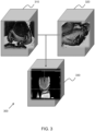
- Figure 3 shows a schematic representation 300 of 3D point cloud based volume stitching according to the method described above.
- Figure 3 shows a first 3D ultrasound image 310 and an additional 3D ultrasound image 320 to be used to generate the composite 3D ultrasound image 330.
- the first 3D ultrasound image and the additional 3D ultrasound images show two perspectives of an anatomical object with an overlapping portion comprising a common anatomical feature.
- Two modules are applied to the first 3D ultrasound image and the second 3D ultrasound image, namely, a classification module and a segmentation module.
- the classification module identifies the presence of relevant objects in each 2D slice of a 3D volume and the segmentation module localizes an object in the 2D slices selected by the classification module in the form of a point cloud.
- the classification module acts to restrict the segmentation module to run within the vicinity of the object of interest, or anatomical feature. In turn this will isolate the object whose surface plot is represented by the point cloud.
- a 3D point cloud is generated in each of the 3D ultrasound images before they are blended to form the composite 3D ultrasound image, a 2D slice 330 of which is shown in Figure 3 .
- Figure 4 shows a comparison between a composite image generated using a rigid stitching method 400 and a composite image generated using a non-rigid stitching method 410.
- the use of rigid registration while performing volume stitching may cause shadow artifacts on moving anatomical structures within the images, such as a fetus (for example a hand or a leg) or a heart valve, due to their natural movements.
- An example of a shadow artifact 415 is shown in image 400.
- Image 410 shows a composite image of the same anatomical feature as image 400; however, as image 410 is generated using a non-rigid stitching method, the presence of shadow artifacts in the final image is significantly reduced.
- shadow artifacts may arise in the composite 3D ultrasound image due to movement of the anatomical feature. These shadow artifacts may be captured through applying non-rigid transformation matrices to the composite 3D ultrasound image in order to do a movement count. In other words, this apparent registration anomaly/error may be used to track anatomical movements in 3D.
- the non-rigid transformation matrix may provide probabilistic loci of the movement of the anatomical feature, which may be used for quantifying/tracking the anatomical movement.
- a computer program may be stored/distributed on a suitable medium, such as an optical storage medium or a solid-state medium supplied together with or as part of other hardware, but may also be distributed in other forms, such as via the Internet or other wired or wireless telecommunication systems.
- a suitable medium such as an optical storage medium or a solid-state medium supplied together with or as part of other hardware, but may also be distributed in other forms, such as via the Internet or other wired or wireless telecommunication systems.
Claims (13)
- Computerimplementiertes Verfahren zum Erlangen eines zusammengesetzten 3D-Ultraschallbilds eines Bereichs von Interesse, das Verfahren umfassend: (110) Erlangen vorläufiger Ultraschalldaten von einem Bereich von Interesse eines Subjekts; (120) Identifizieren eines anatomischen Merkmals innerhalb des Bereichs von Interesse basierend auf den vorläufigen Ultraschalldaten; (130) Bestimmen einer ersten Bildgebungsposition und einer oder mehrerer zusätzlicher Bildgebungspositionen basierend auf dem anatomischen Merkmal; (140) Erlangen eines ersten 3D-Ultraschallbilds von der ersten Bildgebungsposition und eines oder mehrerer zusätzlicher 3D-Ultraschallbilder von der einen oder den mehreren zusätzlichen Bildgebungspositionen, wobei ein Abschnitt des ersten 3D-Ultraschallbilds einen Abschnitt des einen oder der mehreren zusätzlichen 3D-Ultraschallbilder überlappt, wodurch ein überlappender Abschnitt gebildet wird und wobei der überlappende Abschnitt das anatomische Merkmal umfasst; (150) Ausführen von räumlicher Registrierung zwischen dem ersten 3D-Ultraschallbild und dem einen oder den mehreren zusätzlichen 3D-Ultraschallbildern basierend auf dem anatomischen Merkmal, wobei ein Ausführen von räumlicher Registrierung Folgendes umfasst: erzeugen einer 3D-Punktwolke innerhalb des ersten 3D-Ultraschallbilds und des einen oder der mehreren zusätzlichen 3D-Ultraschallbilder, wobei die 3D-Punktwolke eine Oberfläche innerhalb des ersten 3D-Ultraschallbilds und eine Oberfläche innerhalb des einen oder der mehreren zusätzlichen 3D-Ultraschallbilder darstellt; und erzeugen einer Wahrscheinlichkeitskarte basierend auf der 3D-Punktwolke, wobei die Wahrscheinlichkeitskarte einen Konfidenzwert des anatomischen Merkmals darstellt, das einen gegebenen Punkt innerhalb des ersten 3D-Ultraschallbilds und des einen oder der mehreren zusätzlichen 3D-Ultraschallbilder belegt; und (160) Mischen des ersten 3D-Ultraschallbilds und des einen oder der mehreren zusätzlichen 3D-Ultraschallbilder basierend auf der räumlichen Registrierung, wodurch ein zusammengesetztes 3D-Ultraschallbild erzeugt wird, wobei ein Mischen des ersten 3D-Ultraschallbilds und des einen oder der mehreren zusätzlichen 3D-Ultraschallbilder auf der Wahrscheinlichkeitskarte basiert.
- Verfahren nach Anspruch 1, wobei das Verfahren ferner ein Bestimmen einer Bewegung des anatomischen Merkmals basierend auf dem zusammengesetzten 3D-Ultraschallbild umfasst.
- Verfahren nach Anspruch 2, wobei ein Bestimmen der Bewegung des anatomischen Merkmals Folgendes umfasst: anwenden einer nicht starren Transformationsmatrix auf das zusammengesetzte 3D-Ultraschallbild; und identifizieren eines Artefakts basierend auf dem transformierten zusammengesetzten 3D-Ultraschallbild.
- Verfahren nach Anspruch 3, wobei ein Bestimmen der Bewegung des anatomischen Merkmals ein Verfolgen des Artefakts umfasst.
- Verfahren nach einem der Ansprüche 1 bis 4, wobei ein Ausführen von räumlicher Registrierung ein Verwenden eines maschinellen Lernalgorithmus umfasst.
- Verfahren nach Anspruch 5, wobei der Algorithmus für maschinelles Lernen angepasst ist, um basierend auf der 3D-Punktwolke ein Stitching auf zwei Ebenen auszuführen.
- Verfahren nach einem der Ansprüche 1 bis 6, wobei ein Ausführen von räumlicher Registrierung ein Identifizieren einer Position des anatomischen Merkmals innerhalb des ersten 3D-Ultraschallbilds und des einen oder der mehreren zusätzlichen 3D-Ultraschallbilder umfasst, wenn der Konfidenzwert größer ist als ein vorbestimmter Wert.
- Verfahren nach einem der Ansprüche 1 bis 7, wobei dein Mischen des ersten 3D-Ultraschallbilds und des einen oder der mehreren zusätzlichen 3D-Ultraschallbilder ein Erzeugen einer 3D-Konfidenzkarte des überlappenden Abschnitts basierend auf der Wahrscheinlichkeitskarte umfasst.
- Verfahren nach einem der Ansprüche 1 bis 8, wobei ein Mischen des ersten 3D-Ultraschallbilds und des einen oder der mehreren zusätzlichen 3D-Ultraschallbilder ein Anwenden von Poisson-Mischung auf das erste 3D-Ultraschallbild und das eine oder die mehreren zusätzlichen 3D-Ultraschallbilder umfasst.
- Computerprogramm, umfassend Computerprogrammcode-Einrichtungen, die angepasst sind, um, wenn das Computerprogramm auf einem Computer läuft, das Verfahren nach einem der Ansprüche 1 bis 9 zu implementieren.
- Verarbeitungseinheit (30), wobei die Verarbeitungseinheit zu Folgendem angepasst ist: erlangen vorläufiger Ultraschalldaten von einem Bereich von Interesse eines Subjekts; identifizieren eines anatomischen Merkmals innerhalb des Bereichs von Interesse basierend auf den vorläufigen Ultraschalldaten; bestimmen einer ersten Bildgebungsposition und einer oder mehrerer zusätzlicher Bildgebungspositionen basierend auf dem anatomischen Merkmal; erlangen eines ersten 3D-Ultraschallbilds von der ersten Bildgebungsposition und eines oder mehrerer zusätzlicher 3D-Ultraschallbilder von der einen oder den mehreren zusätzlichen Bildgebungspositionen, wobei ein Abschnitt des ersten 3D-Ultraschallbilds einen Abschnitt des einen oder der mehreren zusätzlichen 3D-Ultraschallbilder überlappt, wodurch ein überlappender Abschnitt gebildet wird und wobei der überlappende Abschnitt das anatomische Merkmal umfasst; ausführen von räumlicher Registrierung zwischen dem ersten 3D-Ultraschallbild und dem einen oder den mehreren zusätzlichen 3D-Ultraschallbildern basierend auf dem anatomischen Merkmal, wobei ein Ausführen von räumlicher Registrierung Folgendes umfasst: erzeugen einer 3D-Punktwolke innerhalb des ersten 3D-Ultraschallbilds und des einen oder der mehreren zusätzlichen 3D-Ultraschallbilder, wobei die 3D-Punktwolke eine Oberfläche innerhalb des ersten 3D-Ultraschallbilds und eine Oberfläche innerhalb des einen oder der mehreren zusätzlichen 3D-Ultraschallbilder darstellt; und erzeugen einer Wahrscheinlichkeitskarte basierend auf der 3D-Punktwolke, wobei die Wahrscheinlichkeitskarte einen Konfidenzwert des anatomischen Merkmals darstellt, das einen gegebenen Punkt innerhalb des ersten 3D-Ultraschallbilds und des einen oder der mehreren zusätzlichen 3D-Ultraschallbilder belegt; und mischen des ersten 3D-Ultraschallbilds und des einen oder der mehreren zusätzlichen 3D-Ultraschallbilder basierend auf der räumlichen Registrierung, wodurch ein zusammengesetztes 3D-Ultraschallbild erzeugt wird, wobei ein Mischen des ersten 3D-Ultraschallbilds und des einen oder der mehreren zusätzlichen 3D-Ultraschallbilder auf der Wahrscheinlichkeitskarte basiert.
- Ultraschallsystem (2), das System umfassend: eine Verarbeitungseinheit (30) nach Anspruch 11; und eine Ultraschallsonde (4), die angepasst ist, um 4D-Ultraschalldaten zu erfassen.
- System nach Anspruch 12, wobei die Ultraschallsonde eines oder mehrere von Folgenden umfasst: einen Bewegungssensor; einen elektromagnetischen Tracker; und einen Sprung-Tracker.
Applications Claiming Priority (3)
| Application Number | Priority Date | Filing Date | Title |
|---|---|---|---|
| US201962815484P | 2019-03-08 | 2019-03-08 | |
| EP19163454.2A EP3711677A1 (de) | 2019-03-18 | 2019-03-18 | Verfahren und systeme zur erfassung von 3d-ultraschallbildern |
| PCT/EP2020/056051 WO2020182670A1 (en) | 2019-03-08 | 2020-03-06 | Methods and systems for acquiring composite 3d ultrasound images |
Publications (2)
| Publication Number | Publication Date |
|---|---|
| EP3934539A1 EP3934539A1 (de) | 2022-01-12 |
| EP3934539B1 true EP3934539B1 (de) | 2023-11-29 |
Family
ID=65818336
Family Applications (2)
| Application Number | Title | Priority Date | Filing Date |
|---|---|---|---|
| EP19163454.2A Withdrawn EP3711677A1 (de) | 2019-03-08 | 2019-03-18 | Verfahren und systeme zur erfassung von 3d-ultraschallbildern |
| EP20707470.9A Active EP3934539B1 (de) | 2019-03-08 | 2020-03-06 | Verfahren und systeme zur erfassung von 3d-ultraschallbildern |
Family Applications Before (1)
| Application Number | Title | Priority Date | Filing Date |
|---|---|---|---|
| EP19163454.2A Withdrawn EP3711677A1 (de) | 2019-03-08 | 2019-03-18 | Verfahren und systeme zur erfassung von 3d-ultraschallbildern |
Country Status (5)
| Country | Link |
|---|---|
| US (1) | US20220167947A1 (de) |
| EP (2) | EP3711677A1 (de) |
| JP (1) | JP7346586B2 (de) |
| CN (1) | CN113543721A (de) |
| WO (1) | WO2020182670A1 (de) |
Families Citing this family (3)
| Publication number | Priority date | Publication date | Assignee | Title |
|---|---|---|---|---|
| CN113744280A (zh) * | 2021-07-20 | 2021-12-03 | 北京旷视科技有限公司 | 图像处理方法、装置、设备及介质 |
| CN114287963A (zh) * | 2021-12-30 | 2022-04-08 | 重庆海扶医疗科技股份有限公司 | 图像处理方法、装置、电子设备及计算机可读介质 |
| CN115861563B (zh) * | 2022-12-28 | 2023-10-03 | 无锡东如科技有限公司 | 一种图拓扑刚性点云配准的三维重建方法 |
Family Cites Families (23)
| Publication number | Priority date | Publication date | Assignee | Title |
|---|---|---|---|---|
| US6283919B1 (en) | 1996-11-26 | 2001-09-04 | Atl Ultrasound | Ultrasonic diagnostic imaging with blended tissue harmonic signals |
| US6458083B1 (en) | 1996-11-26 | 2002-10-01 | Koninklijke Philips Electronics N.V. | Ultrasonic harmonic imaging with adaptive image formation |
| US6013032A (en) | 1998-03-13 | 2000-01-11 | Hewlett-Packard Company | Beamforming methods and apparatus for three-dimensional ultrasound imaging using two-dimensional transducer array |
| US5997479A (en) | 1998-05-28 | 1999-12-07 | Hewlett-Packard Company | Phased array acoustic systems with intra-group processors |
| US6530885B1 (en) | 2000-03-17 | 2003-03-11 | Atl Ultrasound, Inc. | Spatially compounded three dimensional ultrasonic images |
| US6443896B1 (en) | 2000-08-17 | 2002-09-03 | Koninklijke Philips Electronics N.V. | Method for creating multiplanar ultrasonic images of a three dimensional object |
| US6468216B1 (en) | 2000-08-24 | 2002-10-22 | Kininklijke Philips Electronics N.V. | Ultrasonic diagnostic imaging of the coronary arteries |
| US20070255137A1 (en) * | 2006-05-01 | 2007-11-01 | Siemens Medical Solutions Usa, Inc. | Extended volume ultrasound data display and measurement |
| EP2225724A1 (de) * | 2007-12-18 | 2010-09-08 | Koninklijke Philips Electronics N.V. | System zur multimodalen fusion von abbildungsdaten auf basis statistischer anatomie-modelle |
| JP5269427B2 (ja) | 2008-01-31 | 2013-08-21 | 株式会社東芝 | 超音波診断装置、画像診断装置、及びプログラム |
| US20130289407A1 (en) * | 2010-09-14 | 2013-10-31 | Samsung Medison Co., Ltd. | 3d ultrasound system for extending view of image and method for operating the 3d ultrasound system |
| EP2680778B1 (de) * | 2011-03-03 | 2019-07-31 | Koninklijke Philips N.V. | System und verfahren zur automatisierten initialisierung und registrierung eines navigationssystems |
| US9179890B2 (en) * | 2011-07-14 | 2015-11-10 | Siemens Aktiengesellschaft | Model-based positioning for intracardiac echocardiography volume stitching |
| EP2807978A1 (de) * | 2013-05-28 | 2014-12-03 | Universität Bern | Verfahren und System zur 3D-Erfassung von Ultraschallbildern |
| US9700284B2 (en) * | 2013-11-13 | 2017-07-11 | Siemens Medical Solutions Usa, Inc. | Three-dimensional ultrasound reconstruction with confidence information |
| US10743844B2 (en) * | 2014-07-29 | 2020-08-18 | Koninklijke Philips N.V. | Ultrasound imaging apparatus |
| US10398412B2 (en) * | 2015-03-31 | 2019-09-03 | Aaron Fenster | 3D ultrasound image stitching |
| JP6574532B2 (ja) | 2016-04-26 | 2019-09-11 | コーニンクレッカ フィリップス エヌ ヴェKoninklijke Philips N.V. | 超音波胎児撮像に対する3d画像合成 |
| JP6868646B2 (ja) * | 2016-05-12 | 2021-05-12 | フジフィルム ソノサイト インコーポレイテッド | 医療画像における構造物寸法を決定するシステム及び方法 |
| JP6629492B2 (ja) * | 2016-11-29 | 2020-01-15 | コーニンクレッカ フィリップス エヌ ヴェKoninklijke Philips N.V. | 超音波イメージングシステム及び方法 |
| AU2018316801B2 (en) * | 2017-08-16 | 2023-12-21 | Mako Surgical Corp. | Ultrasound bone registration with learning-based segmentation and sound speed calibration |
| US10248981B1 (en) * | 2018-04-10 | 2019-04-02 | Prisma Systems Corporation | Platform and acquisition system for generating and maintaining digital product visuals |
| BR112020023312A2 (pt) * | 2018-06-19 | 2021-02-02 | The Board Of Trustees Of The Leland Stanford Junior University | composição e registro de imagem não rígido para redução de pontos de ultrassom |
-
2019
- 2019-03-18 EP EP19163454.2A patent/EP3711677A1/de not_active Withdrawn
-
2020
- 2020-03-06 US US17/436,713 patent/US20220167947A1/en active Pending
- 2020-03-06 CN CN202080019585.5A patent/CN113543721A/zh active Pending
- 2020-03-06 EP EP20707470.9A patent/EP3934539B1/de active Active
- 2020-03-06 JP JP2021552995A patent/JP7346586B2/ja active Active
- 2020-03-06 WO PCT/EP2020/056051 patent/WO2020182670A1/en active Application Filing
Also Published As
| Publication number | Publication date |
|---|---|
| CN113543721A (zh) | 2021-10-22 |
| EP3934539A1 (de) | 2022-01-12 |
| US20220167947A1 (en) | 2022-06-02 |
| EP3711677A1 (de) | 2020-09-23 |
| JP2022524360A (ja) | 2022-05-02 |
| JP7346586B2 (ja) | 2023-09-19 |
| WO2020182670A1 (en) | 2020-09-17 |
Similar Documents
| Publication | Publication Date | Title |
|---|---|---|
| EP3934539B1 (de) | Verfahren und systeme zur erfassung von 3d-ultraschallbildern | |
| EP3923817B1 (de) | Verfahren und systeme zur herzklappenregurgitationsberechnungswertes | |
| EP3866698B1 (de) | Systeme und verfahren zur führung der erfassung eines ultraschallbildes | |
| EP3787517B1 (de) | Systeme und verfahren für ultraschallabtastung | |
| EP3813672A1 (de) | Verfahren und systeme zur durchführung von farb-doppler-ultraschallbildgebung | |
| EP4076208B1 (de) | Systeme und verfahren zur beurteilung einer plazenta | |
| EP4000531A1 (de) | Verfahren und systeme zur verfolgung einer bewegung einer sonde in einem ultraschallsystem | |
| EP3849424B1 (de) | Verfolgen eines werkzeugs in einem ultraschallbild | |
| US20220039773A1 (en) | Systems and methods for tracking a tool in an ultrasound image | |
| EP4132364B1 (de) | Verfahren und systeme zur herstellung eines 3d-vektor-strömungsfeldes | |
| EP4223227A1 (de) | Verfahren und systeme zur durchführung fötaler gewichtsschätzungen | |
| EP4159139A1 (de) | System und verfahren zur segmentierung einer anatomischen struktur | |
| WO2023052178A1 (en) | System and method for segmenting an anatomical structure |
Legal Events
| Date | Code | Title | Description |
|---|---|---|---|
| STAA | Information on the status of an ep patent application or granted ep patent |
Free format text: STATUS: UNKNOWN |
|
| STAA | Information on the status of an ep patent application or granted ep patent |
Free format text: STATUS: THE INTERNATIONAL PUBLICATION HAS BEEN MADE |
|
| PUAI | Public reference made under article 153(3) epc to a published international application that has entered the european phase |
Free format text: ORIGINAL CODE: 0009012 |
|
| STAA | Information on the status of an ep patent application or granted ep patent |
Free format text: STATUS: REQUEST FOR EXAMINATION WAS MADE |
|
| 17P | Request for examination filed |
Effective date: 20211008 |
|
| AK | Designated contracting states |
Kind code of ref document: A1 Designated state(s): AL AT BE BG CH CY CZ DE DK EE ES FI FR GB GR HR HU IE IS IT LI LT LU LV MC MK MT NL NO PL PT RO RS SE SI SK SM TR |
|
| DAV | Request for validation of the european patent (deleted) | ||
| DAX | Request for extension of the european patent (deleted) | ||
| GRAP | Despatch of communication of intention to grant a patent |
Free format text: ORIGINAL CODE: EPIDOSNIGR1 |
|
| STAA | Information on the status of an ep patent application or granted ep patent |
Free format text: STATUS: GRANT OF PATENT IS INTENDED |
|
| INTG | Intention to grant announced |
Effective date: 20230707 |
|
| GRAS | Grant fee paid |
Free format text: ORIGINAL CODE: EPIDOSNIGR3 |
|
| GRAA | (expected) grant |
Free format text: ORIGINAL CODE: 0009210 |
|
| STAA | Information on the status of an ep patent application or granted ep patent |
Free format text: STATUS: THE PATENT HAS BEEN GRANTED |
|
| AK | Designated contracting states |
Kind code of ref document: B1 Designated state(s): AL AT BE BG CH CY CZ DE DK EE ES FI FR GB GR HR HU IE IS IT LI LT LU LV MC MK MT NL NO PL PT RO RS SE SI SK SM TR |
|
| REG | Reference to a national code |
Ref country code: GB Ref legal event code: FG4D |
|
| REG | Reference to a national code |
Ref country code: CH Ref legal event code: EP |
|
| REG | Reference to a national code |
Ref country code: DE Ref legal event code: R096 Ref document number: 602020021857 Country of ref document: DE |
|
| REG | Reference to a national code |
Ref country code: IE Ref legal event code: FG4D |
|
| REG | Reference to a national code |
Ref country code: DE Ref legal event code: R084 Ref document number: 602020021857 Country of ref document: DE |
|
| REG | Reference to a national code |
Ref country code: GB Ref legal event code: 746 Effective date: 20240117 |
|
| REG | Reference to a national code |
Ref country code: LT Ref legal event code: MG9D |
|
| REG | Reference to a national code |
Ref country code: NL Ref legal event code: MP Effective date: 20231129 |
|
| PG25 | Lapsed in a contracting state [announced via postgrant information from national office to epo] |
Ref country code: GR Free format text: LAPSE BECAUSE OF FAILURE TO SUBMIT A TRANSLATION OF THE DESCRIPTION OR TO PAY THE FEE WITHIN THE PRESCRIBED TIME-LIMIT Effective date: 20240301 |
|
| PG25 | Lapsed in a contracting state [announced via postgrant information from national office to epo] |
Ref country code: IS Free format text: LAPSE BECAUSE OF FAILURE TO SUBMIT A TRANSLATION OF THE DESCRIPTION OR TO PAY THE FEE WITHIN THE PRESCRIBED TIME-LIMIT Effective date: 20240329 |
|
| PG25 | Lapsed in a contracting state [announced via postgrant information from national office to epo] |
Ref country code: LT Free format text: LAPSE BECAUSE OF FAILURE TO SUBMIT A TRANSLATION OF THE DESCRIPTION OR TO PAY THE FEE WITHIN THE PRESCRIBED TIME-LIMIT Effective date: 20231129 |
|
| PG25 | Lapsed in a contracting state [announced via postgrant information from national office to epo] |
Ref country code: ES Free format text: LAPSE BECAUSE OF FAILURE TO SUBMIT A TRANSLATION OF THE DESCRIPTION OR TO PAY THE FEE WITHIN THE PRESCRIBED TIME-LIMIT Effective date: 20231129 |
|
| PG25 | Lapsed in a contracting state [announced via postgrant information from national office to epo] |
Ref country code: LT Free format text: LAPSE BECAUSE OF FAILURE TO SUBMIT A TRANSLATION OF THE DESCRIPTION OR TO PAY THE FEE WITHIN THE PRESCRIBED TIME-LIMIT Effective date: 20231129 Ref country code: IS Free format text: LAPSE BECAUSE OF FAILURE TO SUBMIT A TRANSLATION OF THE DESCRIPTION OR TO PAY THE FEE WITHIN THE PRESCRIBED TIME-LIMIT Effective date: 20240329 Ref country code: GR Free format text: LAPSE BECAUSE OF FAILURE TO SUBMIT A TRANSLATION OF THE DESCRIPTION OR TO PAY THE FEE WITHIN THE PRESCRIBED TIME-LIMIT Effective date: 20240301 Ref country code: ES Free format text: LAPSE BECAUSE OF FAILURE TO SUBMIT A TRANSLATION OF THE DESCRIPTION OR TO PAY THE FEE WITHIN THE PRESCRIBED TIME-LIMIT Effective date: 20231129 Ref country code: BG Free format text: LAPSE BECAUSE OF FAILURE TO SUBMIT A TRANSLATION OF THE DESCRIPTION OR TO PAY THE FEE WITHIN THE PRESCRIBED TIME-LIMIT Effective date: 20240229 |
|
| PGFP | Annual fee paid to national office [announced via postgrant information from national office to epo] |
Ref country code: DE Payment date: 20240328 Year of fee payment: 5 Ref country code: GB Payment date: 20240319 Year of fee payment: 5 |