EP3933536A1 - Traveling vehicle and traveling vehicle system - Google Patents
Traveling vehicle and traveling vehicle system Download PDFInfo
- Publication number
- EP3933536A1 EP3933536A1 EP19917218.0A EP19917218A EP3933536A1 EP 3933536 A1 EP3933536 A1 EP 3933536A1 EP 19917218 A EP19917218 A EP 19917218A EP 3933536 A1 EP3933536 A1 EP 3933536A1
- Authority
- EP
- European Patent Office
- Prior art keywords
- traveling vehicle
- traveling
- state
- ahead
- led array
- Prior art date
- Legal status (The legal status is an assumption and is not a legal conclusion. Google has not performed a legal analysis and makes no representation as to the accuracy of the status listed.)
- Pending
Links
Images


Classifications
-
- B—PERFORMING OPERATIONS; TRANSPORTING
- B60—VEHICLES IN GENERAL
- B60W—CONJOINT CONTROL OF VEHICLE SUB-UNITS OF DIFFERENT TYPE OR DIFFERENT FUNCTION; CONTROL SYSTEMS SPECIALLY ADAPTED FOR HYBRID VEHICLES; ROAD VEHICLE DRIVE CONTROL SYSTEMS FOR PURPOSES NOT RELATED TO THE CONTROL OF A PARTICULAR SUB-UNIT
- B60W60/00—Drive control systems specially adapted for autonomous road vehicles
- B60W60/001—Planning or execution of driving tasks
-
- H—ELECTRICITY
- H10—SEMICONDUCTOR DEVICES; ELECTRIC SOLID-STATE DEVICES NOT OTHERWISE PROVIDED FOR
- H10P—GENERIC PROCESSES OR APPARATUS FOR THE MANUFACTURE OR TREATMENT OF DEVICES COVERED BY CLASS H10
- H10P72/00—Handling or holding of wafers, substrates or devices during manufacture or treatment thereof
- H10P72/06—Apparatus for monitoring, sorting, marking, testing or measuring
- H10P72/0606—Position monitoring, e.g. misposition detection or presence detection
-
- B—PERFORMING OPERATIONS; TRANSPORTING
- B60—VEHICLES IN GENERAL
- B60W—CONJOINT CONTROL OF VEHICLE SUB-UNITS OF DIFFERENT TYPE OR DIFFERENT FUNCTION; CONTROL SYSTEMS SPECIALLY ADAPTED FOR HYBRID VEHICLES; ROAD VEHICLE DRIVE CONTROL SYSTEMS FOR PURPOSES NOT RELATED TO THE CONTROL OF A PARTICULAR SUB-UNIT
- B60W30/00—Purposes of road vehicle drive control systems not related to the control of a particular sub-unit, e.g. of systems using conjoint control of vehicle sub-units
- B60W30/10—Path keeping
-
- B—PERFORMING OPERATIONS; TRANSPORTING
- B60—VEHICLES IN GENERAL
- B60W—CONJOINT CONTROL OF VEHICLE SUB-UNITS OF DIFFERENT TYPE OR DIFFERENT FUNCTION; CONTROL SYSTEMS SPECIALLY ADAPTED FOR HYBRID VEHICLES; ROAD VEHICLE DRIVE CONTROL SYSTEMS FOR PURPOSES NOT RELATED TO THE CONTROL OF A PARTICULAR SUB-UNIT
- B60W30/00—Purposes of road vehicle drive control systems not related to the control of a particular sub-unit, e.g. of systems using conjoint control of vehicle sub-units
- B60W30/14—Adaptive cruise control
- B60W30/16—Control of distance between vehicles, e.g. keeping a distance to preceding vehicle
- B60W30/165—Automatically following the path of a preceding lead vehicle, e.g. "electronic tow-bar"
-
- B—PERFORMING OPERATIONS; TRANSPORTING
- B60—VEHICLES IN GENERAL
- B60W—CONJOINT CONTROL OF VEHICLE SUB-UNITS OF DIFFERENT TYPE OR DIFFERENT FUNCTION; CONTROL SYSTEMS SPECIALLY ADAPTED FOR HYBRID VEHICLES; ROAD VEHICLE DRIVE CONTROL SYSTEMS FOR PURPOSES NOT RELATED TO THE CONTROL OF A PARTICULAR SUB-UNIT
- B60W60/00—Drive control systems specially adapted for autonomous road vehicles
- B60W60/001—Planning or execution of driving tasks
- B60W60/0015—Planning or execution of driving tasks specially adapted for safety
-
- B—PERFORMING OPERATIONS; TRANSPORTING
- B60—VEHICLES IN GENERAL
- B60W—CONJOINT CONTROL OF VEHICLE SUB-UNITS OF DIFFERENT TYPE OR DIFFERENT FUNCTION; CONTROL SYSTEMS SPECIALLY ADAPTED FOR HYBRID VEHICLES; ROAD VEHICLE DRIVE CONTROL SYSTEMS FOR PURPOSES NOT RELATED TO THE CONTROL OF A PARTICULAR SUB-UNIT
- B60W60/00—Drive control systems specially adapted for autonomous road vehicles
- B60W60/001—Planning or execution of driving tasks
- B60W60/0027—Planning or execution of driving tasks using trajectory prediction for other traffic participants
-
- G—PHYSICS
- G06—COMPUTING OR CALCULATING; COUNTING
- G06V—IMAGE OR VIDEO RECOGNITION OR UNDERSTANDING
- G06V20/00—Scenes; Scene-specific elements
- G06V20/50—Context or environment of the image
- G06V20/56—Context or environment of the image exterior to a vehicle by using sensors mounted on the vehicle
- G06V20/58—Recognition of moving objects or obstacles, e.g. vehicles or pedestrians; Recognition of traffic objects, e.g. traffic signs, traffic lights or roads
-
- H—ELECTRICITY
- H10—SEMICONDUCTOR DEVICES; ELECTRIC SOLID-STATE DEVICES NOT OTHERWISE PROVIDED FOR
- H10P—GENERIC PROCESSES OR APPARATUS FOR THE MANUFACTURE OR TREATMENT OF DEVICES COVERED BY CLASS H10
- H10P72/00—Handling or holding of wafers, substrates or devices during manufacture or treatment thereof
- H10P72/06—Apparatus for monitoring, sorting, marking, testing or measuring
- H10P72/0612—Production flow monitoring, e.g. for increasing throughput
-
- H—ELECTRICITY
- H10—SEMICONDUCTOR DEVICES; ELECTRIC SOLID-STATE DEVICES NOT OTHERWISE PROVIDED FOR
- H10P—GENERIC PROCESSES OR APPARATUS FOR THE MANUFACTURE OR TREATMENT OF DEVICES COVERED BY CLASS H10
- H10P72/00—Handling or holding of wafers, substrates or devices during manufacture or treatment thereof
- H10P72/06—Apparatus for monitoring, sorting, marking, testing or measuring
- H10P72/0618—Apparatus for monitoring, sorting, marking, testing or measuring using identification means, e.g. labels on substrates or labels on containers
-
- H—ELECTRICITY
- H10—SEMICONDUCTOR DEVICES; ELECTRIC SOLID-STATE DEVICES NOT OTHERWISE PROVIDED FOR
- H10P—GENERIC PROCESSES OR APPARATUS FOR THE MANUFACTURE OR TREATMENT OF DEVICES COVERED BY CLASS H10
- H10P72/00—Handling or holding of wafers, substrates or devices during manufacture or treatment thereof
- H10P72/30—Handling or holding of wafers, substrates or devices during manufacture or treatment thereof for conveying, e.g. between different workstations
- H10P72/32—Handling or holding of wafers, substrates or devices during manufacture or treatment thereof for conveying, e.g. between different workstations between different workstations
- H10P72/3208—Changing the direction of the conveying path
-
- H—ELECTRICITY
- H10—SEMICONDUCTOR DEVICES; ELECTRIC SOLID-STATE DEVICES NOT OTHERWISE PROVIDED FOR
- H10P—GENERIC PROCESSES OR APPARATUS FOR THE MANUFACTURE OR TREATMENT OF DEVICES COVERED BY CLASS H10
- H10P72/00—Handling or holding of wafers, substrates or devices during manufacture or treatment thereof
- H10P72/30—Handling or holding of wafers, substrates or devices during manufacture or treatment thereof for conveying, e.g. between different workstations
- H10P72/32—Handling or holding of wafers, substrates or devices during manufacture or treatment thereof for conveying, e.g. between different workstations between different workstations
- H10P72/3216—Handling or holding of wafers, substrates or devices during manufacture or treatment thereof for conveying, e.g. between different workstations between different workstations using a general scheme of a conveying path within a factory
-
- H—ELECTRICITY
- H10—SEMICONDUCTOR DEVICES; ELECTRIC SOLID-STATE DEVICES NOT OTHERWISE PROVIDED FOR
- H10P—GENERIC PROCESSES OR APPARATUS FOR THE MANUFACTURE OR TREATMENT OF DEVICES COVERED BY CLASS H10
- H10P72/00—Handling or holding of wafers, substrates or devices during manufacture or treatment thereof
- H10P72/30—Handling or holding of wafers, substrates or devices during manufacture or treatment thereof for conveying, e.g. between different workstations
- H10P72/32—Handling or holding of wafers, substrates or devices during manufacture or treatment thereof for conveying, e.g. between different workstations between different workstations
- H10P72/3221—Overhead conveying
-
- B—PERFORMING OPERATIONS; TRANSPORTING
- B60—VEHICLES IN GENERAL
- B60W—CONJOINT CONTROL OF VEHICLE SUB-UNITS OF DIFFERENT TYPE OR DIFFERENT FUNCTION; CONTROL SYSTEMS SPECIALLY ADAPTED FOR HYBRID VEHICLES; ROAD VEHICLE DRIVE CONTROL SYSTEMS FOR PURPOSES NOT RELATED TO THE CONTROL OF A PARTICULAR SUB-UNIT
- B60W2420/00—Indexing codes relating to the type of sensors based on the principle of their operation
- B60W2420/40—Photo, light or radio wave sensitive means, e.g. infrared sensors
- B60W2420/403—Image sensing, e.g. optical camera
Definitions
- An aspect of the present invention relates to a traveling vehicle and a traveling vehicle system.
- a transportation vehicle system (traveling vehicle system) is known in which a plurality of transportation vehicles (traveling vehicles) equipped with forward-looking sensors travel on a predetermined path.
- Patent Document 1 discloses a transportation vehicle system that measures the inter-vehicle distance to a preceding transportation vehicle for each transportation vehicle, determines a speed relative to the preceding transportation vehicle based on a change per time of the measured inter-vehicle distance, and controls the speed of the transportation vehicle itself based on the measured inter-vehicle distance.
- Patent Document 1 Japanese Unexamined Patent Publication No. 2007-25745
- the transportation capability is requested to be increased by traveling with a minimum distance between traveling vehicles (with a shorter inter-vehicle distance).
- the traveling vehicle behind does not start stopping operation until the inter-vehicle distance becomes equal to or smaller than a predetermined value, and, therefore, the traveling vehicle behind is unable to stop to follow the stop of the traveling vehicle ahead instantaneously.
- An object of an aspect of the present invention is to provide a traveling vehicle and a traveling vehicle system capable of promptly performing operation appropriate for the state of the traveling vehicle ahead.
- a traveling vehicle travels along a predetermined traveling path.
- the traveling vehicle includes a main body, a traveling unit configured to allow the main body to travel along the traveling path, a display unit disposed at the main body and configured to switch a display manner according to a state of the traveling vehicle itself, an imager configured to capture an image of the display unit provided at a front traveling vehicle located ahead of the traveling vehicle itself, and a control unit configured to acquire a state of the front traveling vehicle based on the display manner captured by the imager, and to control the traveling unit of the traveling vehicle itself based on the acquired state.
- the traveling vehicle behind since a display manner that varies according to a state of the traveling vehicle is indicated on the display unit, the traveling vehicle behind that acquires the display manner of the display unit with the imager can determine a state of the traveling vehicle ahead instantaneously. With this configuration, the traveling vehicle behind can promptly perform operation appropriate for the state of the traveling vehicle ahead.
- the display unit may switch the display manner according to a traveling state of the traveling vehicle itself, and the traveling state may include an accelerated state and a decelerated state.
- the traveling state may include an accelerated state and a decelerated state.
- the display unit may switch the display manner according to a present location of the traveling vehicle itself.
- This configuration enables a traveling vehicle behind to grasp at least the present location of the traveling vehicle itself. With this configuration, the traveling vehicle behind can accurately grasp the positional relation to the traveling vehicle ahead.
- the traveling vehicle may further include an identifier disposed near the display unit.
- the control unit may acquire a state of the front traveling vehicle based on the display manner captured by the imager and a positional relation between the display unit and the identifier, and may control the traveling unit of the traveling vehicle itself based on the acquired state.
- an unintended display unit for example, a display unit that is not provided on the traveling vehicle
- a state of the traveling vehicle ahead can be acquired accurately based on the display unit captured through a mirror.
- a traveling vehicle system may include a plurality of the traveling vehicles.
- the traveling vehicle system with this configuration since each individual traveling vehicle can promptly perform operation appropriate for the state of the traveling vehicle ahead, the transportation performance of the traveling vehicle system as a whole can be increased.
- the traveling vehicle system may further include a mirror disposed along the traveling path and configured to reflect the display unit disposed at the front traveling vehicle.
- the control unit may acquire a state of the front traveling vehicle based on the display manner captured by the imager through the mirror.
- the range of visibility can be widened because of the mirror interposed, for example, when the traveling vehicle ahead is located beyond a curve section as viewed from the traveling vehicle behind, and the range in which the traveling vehicle ahead is visible is narrow.
- operation appropriate for the state of the traveling vehicle ahead can be promptly performed.
- a traveling vehicle system 1 is, for example, a system for transporting an article 10 (see FIG. 2 ) between placement sections 9 and 9 using an overhead traveling vehicle 6 movable along a track (a predetermined traveling path) 4.
- the article 10 include containers such as a front opening unified pod (FOUP) storing a plurality of semiconductor wafers and a reticle pod storing a glass substrate, and common parts.
- FOUP front opening unified pod
- the traveling vehicle system 1 in a factory is taken as an example, in which the overhead traveling vehicle 6 (hereinafter simply referred to as "traveling vehicle 6") travels along the one-way track 4 laid on the ceiling in the factory.
- the traveling vehicle system 1 includes the track 4, mirrors 45A and 45B, a plurality of traveling vehicles 6, and a plurality of placement sections 9.
- the track 4 is laid, for example, in the vicinity of the ceiling that is a space above the worker's head.
- the track 4 is, for example, suspended from the ceiling.
- the track 4 is a predetermined traveling path for the traveling vehicles 6 to travel.
- the track 4 is supported by struts 40 and 40.
- the mirrors 45A and 45B are provided along the track 4 and reflect a light emitting diode (LED) array (display unit) 55 (see FIG. 3 ) provided on the traveling vehicle 6.
- the track 4 includes a branching section 41 including an incomingpath 41Athat comes into a predetermined location along one direction, a first outgoing path 41B that goes out from the predetermined location along the one direction, and a second outgoing path 41C that goes out from the predetermined location in a direction different from the one direction.
- the mirror 45A is arranged near (to the side of) the branching section 41.
- the mirror 45A reflects the LED array 55 provided at a drop-preventing cover 33a of a traveling vehicle 6 ahead (front traveling vehicle) as viewed from one traveling vehicle 6.
- the track 4 also includes a merging section 43 including a first incoming path 43A that comes into a predetermined location along one direction, a second incoming path 43B that comes into the predetermined location from a direction different from the one direction, and an outgoing path 43C that goes out from the predetermined location in a direction different from the one direction.
- the mirror 45B is arranged near the merging section 43.
- the mirror 45B reflects the LED array 55 provided at a drop-preventing cover 33b of a traveling vehicle 6 ahead (front traveling vehicle) as viewed from one traveling vehicle 6.
- the traveling vehicle 6 travels along the track 4 and transports the article 10.
- the traveling vehicle 6 is configured to transfer the article 10.
- the traveling vehicle 6 is an automated overhead transportation vehicle.
- the number of traveling vehicles 6 included in the traveling vehicle system 1 is not limited and is more than one.
- the traveling vehicle 6 includes a main body 7, a traveling unit 18, an LED array 55, an identifier (first identifier and second identifier) 57, an imager 8, and a control unit 50.
- the main body 7 includes a main body frame 22, a traverse unit 24, a ⁇ drive 26, an elevation driver 28, an elevation stage 30, and a drop-preventing cover 33.
- the traveling unit 18 includes a motor and allows the traveling vehicle 6 to travel along the track 4.
- the traveling unit 18 includes, for example, a power-receiving communication unit 20 that receives power from the track 4 via wireless charging.
- the traverse unit 24 allows the ⁇ drive 26, the elevation driver 28, and the elevation stage 30 to collectively traverse in a direction normal to the traveling direction of the track 4.
- the ⁇ drive 26 turns at least one of the elevation driver 28 and the elevation stage 30 within a predetermined angle range in a horizontal plane.
- the elevation driver 28 lifts and lowers the elevation stage 30 by reeling or unreeling a hanging member such as wire, rope, and belt.
- the elevation stage 30 has a chuck and can grip or release the article 10.
- a pair of drop-preventing covers 33 are provided, for example, at the front and the rear in the traveling direction of the traveling vehicle 6.
- the drop-preventing covers 33 produce a not-illustrated pawl below the article 10 to be transported and prevent the article 10 from dropping during transportation.
- the placement sections 9 are arranged along the track 4 and provided at locations where the article 10 can be delivered to/from the traveling vehicle 6.
- the placement sections 9 include a buffer and a delivery port.
- the buffer is a placement section on which the article 10 is temporarily placed.
- the buffer is a placement section on which the article 10 is temporarily placed when the article 10 transported by the traveling vehicle 6 is unable to be transferred to a target delivery port, for example, for the reason that another article 10 has been placed on the target delivery port.
- the delivery port is, for example, a placement section for delivering the article 10 to/from a semiconductor processing device (not illustrated) such as a cleaning device, a deposition device, a lithography device, an etching device, a thermal treatment device, and a planarization device.
- a semiconductor processing device such as a cleaning device, a deposition device, a lithography device, an etching device, a thermal treatment device, and a planarization device.
- the processing device is not limited to a specific device and may be a variety of devices.
- the placement sections 9 are arranged to the side of the track 4.
- the traveling vehicle 6 allows the traverse unit 24 to traverse the elevation driver 28 and the like and slightly lifts and lowers the elevation stage 30 to deliver the article 10 to/from the placement section 9.
- the placement sections 9 may be arranged immediately below the track 4. In this case, the traveling vehicle 6 lifts and lowers the elevation stage 30 to deliver the article 10 to/from the placement section 9.
- the LED array 55 is arranged at the drop-preventing cover 33a (33) provided on the rear side of the traveling vehicle 6.
- the LED array 55 may be additionally arranged on the drop-preventing cover 33b (33) provided on the front side of the traveling vehicle 6.
- the LED array 55 is an LED unit having an array of a plurality of (five) LEDs 55A and 55B.
- the LED array 55 switches a display manner according to a state of the traveling vehicle 6 itself (the traveling vehicle 6 having the LED array 55).
- the LED array 55 changes a display manner with a combination of an illuminated LED 55A and a not-illuminated LED 55A among four LEDs 55A (hereinafter simply referred to as "combination of illumination").
- the remaining one LED 55B is used as a parity. That is, it is used to determine whether a combination of illumination of four LEDs 55A is the display manner intended by the control unit 50.
- the switching of display manners in the LED array 55 is performed by the control unit 50.
- the identifier 57 is arranged near (adjacent to) the LED array 55.
- the identifier 57 is a predetermined symbol (mark) .
- the identifier 57 may be, for example, a two-dimensional barcode or may include information such as an identification number for identifying each of a plurality of traveling vehicles 6.
- the imager 8 captures an image of the LED array 55 provided on a traveling vehicle 6 located ahead of the traveling vehicle 6 itself.
- the imager 8 is arranged on the drop-preventing cover 33b (33) provided on the front side of the traveling vehicle 6.
- the imager 8 transmits a captured image obtained by capturing a display manner of the LED array 55 to the control unit 50. As described later, the imager 8 not only captures an image of the LED array 55 provided on a traveling vehicle 6 located ahead of the traveling vehicle 6 itself but also captures an image of the LED array 55 reflected on the mirrors 45A and 45B arranged along the track 4.
- the control unit 50 is an electronic control unit including a central processing unit (CPU) , a read only memory (ROM) , and a random access memory (RAM) .
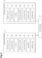
- the control unit 50 controls various operations in the traveling vehicle 6. Specifically, as illustrated in FIG. 4 , the control unit 50 controls the traveling unit 18, the traverse unit 24, the ⁇ drive 26, the elevation driver 28, the elevation stage 30, and the LED array 55.
- the control unit 50 can be configured, for example, as software that is a program stored in the ROM, loaded into the RAM, and executed by the CPU.
- the control unit 50 may be configured as hardware with electronic circuitry, for example.
- the control unit 50 communicates with a controller 60 using a communication line (feeder line) of the track 4.
- the control unit 50 switches a display manner of the LED array 55 according to a traveling state of the traveling vehicle 6 itself. Specifically, for example, when receiving a command from the controller 60 and acquiring that the traveling state of the traveling vehicle 6 itself becomes an acceleration state or a deceleration state, the control unit 50 controls illumination of the LEDs 55A in the LED array 55 to attain a display manner corresponding to the acquired traveling state. In other words, the control unit 50 transmits the traveling state of the traveling vehicle 6 itself to a traveling vehicle 6 behind by switching a display manner of the LED array 55 provided on the traveling vehicle 6. The control unit 50 also switches a display manner of the LED array 55 according to the present location of the traveling vehicle 6 itself.
- control unit 50 acquires the traveling location of the traveling vehicle 6 itself by reading information such as a barcode attached to the track 4 and then controls illumination of the LEDs 55A in the LED array 55 to attain a display manner corresponding to the acquired traveling location.
- control unit 50 transmits the traveling location of the traveling vehicle 6 itself to a traveling vehicle 6 behind by switching a display manner of the LED array 55 provided on the traveling vehicle 6.
- the control unit 50 acquires a state of a traveling vehicle 6 ahead based on the display manner captured by the imager 8 or the display manner captured by the imager 8 through the mirrors 45A and 45B and controls the traveling unit 18 of the traveling vehicle 6 itself based on the acquired state. Specifically, the control unit 50 acquires a state of a traveling vehicle 6 located ahead, based on the manner of the LED array 55 of the traveling vehicle 6 located ahead that is captured by the imager 8. The control unit 50, for example, extracts a combination of illumination of the LED array 55 from the acquired captured image and refers to combination information in which the states of the traveling vehicle 6 and the combinations of illumination are mapped and stored. The control unit 50 thus acquires the state of the traveling vehicle 6 ahead.
- the control unit 50 controls the traveling unit 18 in accordance with the acquired state of the traveling vehicle 6 ahead. Specifically, the control unit 50 decelerates the traveling unit 18 of the traveling vehicle 6 itself when acquiring that the traveling state of the traveling vehicle 6 ahead is the decelerated state. Furthermore, the control unit 50 accelerates the traveling unit 18 of the traveling vehicle 6 itself when acquiring that the traveling state of the traveling vehicle 6 ahead is the accelerated state.
- the control unit 50 determines whether to control the traveling unit 18, based on the positional relation between the LED array 55 and the identifier 57 in the captured image acquired by the imager 8. For example, when the identifier 57 is recognized at a predetermined position relative to the LED array 55 (for example, the lower left to the LED array 55) in the captured image, the control unit 50 acquires a state of the traveling vehicle 6 ahead from the acquired captured image and controls the traveling unit 18 in accordance with the acquired state. On the other hand, when the identifier 57 is not recognized at a predetermined position relative to the LED array 55 in the captured image, the control unit 50 does not control the traveling unit 18 based on the acquired captured image. In other words, the control unit 50 determines that the acquired display manner is not the one acquired from the LED array 55 provided on the traveling vehicle 6 ahead, and does not control the traveling unit 18.
- the control unit 50 also determines whether the display manner is a mirror image reflected on the mirrors 45A and 45B, based on the positional relation between the LED array 55 and the identifier 57 in the captured image acquired by the imager 8. For example, when the identifier 57 is recognized at a predetermined position relative to the LED array 55 (for example, the lower right to the LED array 55) in the captured image, the control unit 50 determines that it is the captured image (direct image) in which the LED array 55 of the traveling vehicle 6 ahead is directly captured, not through the mirrors 45A and 45B.
- the control unit 50 determines that it is the captured image (mirror image) acquired through the mirrors 45A and 45B.
- the control unit 50 thus can determine whether the acquired combination of illumination of the LED array 55 is the one reflected on the mirrors 45A and 45B.
- the controller 60 is an electronic control unit including a central processing unit (CPU) , a read only memory (ROM) , and a random access memory (RAM) .
- the controller 60 can be configured, for example, as software that is a program stored in the ROM, loaded into the RAM, and executed by the CPU.
- the controller 60 maybe configured as hardware with electronic circuitry, for example.
- the controller 60 transmits a transportation command to the traveling vehicle 6 to transport the article 10.
- the traveling vehicle 6 is monitoring the distance to an obstacle (including a traveling vehicle) ahead, for example, with an obstacle sensor for monitoring a view ahead.
- a traveling vehicle ahead decelerates when the distance to an obstacle ahead is a predetermined distance and stops when the distance to the obstacle ahead is a second predetermined distance shorter than the previous predetermined distance.
- a traveling vehicle behind decelerates when the distance to the traveling vehicle ahead is a predetermined distance and stops when the distance to the traveling vehicle ahead is a second predetermined distance shorter than the predetermined distance.
- the traveling vehicle behind is unable to decelerate until the traveling vehicle behind approaches a predetermined distance.
- the traveling vehicle behind therefore is unable to start deceleration immediately at the timing when the traveling vehicle ahead starts deceleration.
- the traveling vehicle behind therefore need to travel with the inter-vehicle distance kept relatively longer in order to avoid collision with the traveling vehicle ahead, leading to reduction in transportation capability.
- the traveling vehicle 6 ahead decelerates when the distance to the traveling vehicle 6 ahead is a predetermined distance and simultaneously indicates that the state of the traveling vehicle 6 itself is the decelerated state on the LED array 55.
- the traveling vehicle 6 behind determines a state of the traveling vehicle 6 a head based on the combination of illumination of the LED array 55 that is captured by the imager 8.
- the traveling vehicle 6 behind then starts deceleration immediately when it is determined that the traveling vehicle 6 ahead becomes the decelerated state.
- the traveling vehicle 6 behind can start deceleration immediately at the timing when the traveling vehicle 6 ahead starts deceleration.
- the traveling vehicle 6 behind therefore only need to keep the minimum inter-vehicle distance for avoiding collision with the traveling vehicle 6 ahead, leading to improvement in transportation capability.
- a case where a start command is transmitted from the controller 60 simultaneously to the traveling vehicle 6 ahead and the traveling vehicle 6 behind will be described as an example.
- the traveling vehicle 6 is monitoring the distance to an obstacle ahead, for example, with an obstacle sensor for monitoring a view ahead.
- the traveling vehicle ahead confirms that there is no obstacle using an obstacle sensor or the like and thereafter accelerates (starts) .
- the traveling vehicle behind accelerates when the distance to the traveling vehicle ahead is equal to or longer than a predetermined distance.
- the traveling vehicle behind is unable to start acceleration immediately at the timing when the traveling vehicle ahead starts acceleration, for example, because although the traveling vehicle 6 ahead accelerates, there is a waiting time until the traveling vehicle 6 ahead moves away to a predetermined distance from the traveling vehicle behind.
- the operating rate of the traveling vehicle behind therefore decreases by the waiting time, leading to reduction in transportation capability.
- the traveling vehicle 6 ahead indicates that the state of the traveling vehicle 6 itself is the accelerated state on the LED array 55, simultaneously when starting acceleration.
- the traveling vehicle 6 behind determines a state of the traveling vehicle 6 ahead based on the combination of illumination of LED array 55 that is captured by the imager 8.
- the traveling vehicle 6 behind then starts acceleration immediately when it is determined that the traveling vehicle 6 ahead becomes the accelerated state.
- the traveling vehicle 6 behind can start acceleration immediately at the timing when the traveling vehicle 6 ahead starts acceleration.
- the operating rate of the traveling vehicle behind therefore can be increased, leading to improvement in transportation capability.
- the traveling vehicle 6 ahead takes the second outgoing path 41C and the traveling vehicle 6 behind is due to take the first outgoing path 41B at the branching section 41 will be described as an example.
- the traveling vehicle 6 is monitoring the distance to an obstacle ahead, for example, with an obstacle sensor for monitoring a view ahead.
- an obstacle sensor often detects the traveling vehicle 6 ahead even when the traveling vehicle entering the second outgoing path 41C is located at a place where it does not collide with the traveling vehicle 6 behind entering the first out going path 41B.
- entry of the traveling vehicle 6 behind into the branching section 41 is restricted as a consequence, leading to reduction in transportation capability.
- the traveling vehicle 6 ahead acquires the location in the track 4 from a barcode (barcode indicates the location) affixed along the track 4 and indicates the acquired barcode information on the LED array 55.
- the traveling vehicle 6 behind acquires the location of the traveling vehicle 6 ahead based on the combination of illumination of the LED array 55 that is captured by the imager 8.
- the imager 8 of the traveling vehicle 6 behind captures an image of the LED array 55 of the traveling vehicle 6 ahead that is reflected on the mirror 45A provided at the branching section 41.
- the traveling vehicle 6 behind acquires the location of the traveling vehicle 6 ahead based on the combination of illumination of the LED array 55 that is captured by the imager 8.
- the traveling vehicle 6 behind can enter the branching section 41 at the point of time when it is determined that the traveling vehicle 6 ahead has moved to a location where it does not collide with the traveling vehicle 6 behind.
- the unnecessary waiting time otherwise caused at the branching section 41 therefore can be eliminated, thereby increasing the operating rate and leading to improvement in transportation capability.
- the traveling vehicle 6 ahead takes the first incoming path 43A and the traveling vehicle 6 behind takes the second incoming path 43B at the merging section 43 will be described as an example.
- the traveling vehicle 6 is monitoring the distance to an obstacle ahead, for example, with an obstacle sensor for monitoring a view ahead.
- the traveling vehicle 6 in the first incoming path 43A stops at a location where it does not collide with the traveling vehicle 6 entering from the second incoming path 43B the obstacle sensor provided on the traveling vehicle 6 entering from the second incoming path 43B often detects the traveling vehicle stopping at the first incoming path 43A as the traveling vehicle 6 ahead.
- entry of the traveling vehicle 6 behind into the merging section 43 is restricted as a consequence, leading to reduction in transportation capability.
- the traveling vehicle 6 ahead acquires the location in the track 4 from a barcode affixed along the track 4 and indicates the acquiredbarcode information on the LED array 55.
- the traveling vehicle 6 behind acquires the location of the traveling vehicle 6 ahead based on the combination of illumination of the LED array 55 that is captured by the imager 8.
- the imager 8 of the traveling vehicle 6 behind captures an image of the LED array 55 provided at the drop-preventing cover 33a on the front side of the traveling vehicle 6 ahead that is reflected on the mirror 45B provided at the merging section 43.
- the traveling vehicle 6 behind acquires the location of the traveling vehicle 6 ahead based on the combination of illumination of the LED array 55 that is captured by the imager 8.
- the traveling vehicle 6 behind can enter the merging section 43 when it is determined that the traveling vehicle 6 ahead is stopping at a location where it does not collide with the traveling vehicle 6 behind.
- the unnecessary waiting time otherwise caused at the merging section 43 can be eliminated, thereby increasing the operating rate and leading to improvement in transportation capability.
- a state of the traveling vehicle 6 ahead may be acquired through the LED array 55 by a method using wireless radio waves, a method using infrared communication, and a method using wireless feeder.
- the method in the present embodiment is advantageous over the method using wireless radio waves in that communication failure is less likely to occur and communication failure due to change in communication environment over time is less likely to occur.
- the method in the present embodiment is also advantageous over the method using infrared communication in that it is immune to deviation of the optical axis.
- the method in the present embodiment is also advantageous over the method using wireless feeder in that a signal transmission response is fast (latency is short).
- a 3D sensor may be arranged instead of the method of acquiring the location of the traveling vehicle 6 by acquiring the display manner of the LED array 55 provided on the traveling vehicle 6 ahead through the mirrors 45A and 45B with the imager 8.
- the method in the present embodiment can reduce the possibility that the traveling vehicle 6 ahead is hidden behind a structure (rack, post, etc.) and becomes out of sight.
- the traveling vehicle 6 and the traveling vehicle system 1 in the foregoing embodiment since a display manner that varies according to a state of the traveling vehicle 6 (a display manner according to a state of the traveling vehicle 6) is indicated on the LED array 55, the traveling vehicle 6 behind that acquires the display manner of the LED array 55 with the imager 8 can determine a state of the traveling vehicle 6 ahead instantaneously. With this configuration, the traveling vehicle 6 behind can promptly perform operation appropriate for the state of the traveling vehicle 6 ahead.
- the traveling vehicle 6 and the traveling vehicle system 1 in the foregoing embodiment enables the traveling vehicle 6 behind to grasp whether the traveling vehicle 6 itself is in the accelerated state or the decelerated state.
- the traveling vehicle 6 ahead accelerates, the traveling vehicle 6 behind can promptly follow the acceleration, and when the traveling vehicle 6 ahead decelerates, the traveling vehicle 6 behind can promptly follow the deceleration.
- the traveling vehicle 6 and the traveling vehicle system 1 in the foregoing embodiment enables the traveling vehicle 6 behind to grasp the traveling location of the traveling vehicle 6 itself.
- the traveling vehicle 6 behind can accurately grasp the positional relation to the traveling vehicle 6 ahead.
- the distance to the traveling vehicle 6 ahead can be acquired with high precision, or when the traveling vehicle 6 behindmoves, the traveling vehicle 6 can determine with high precision that it will not collide with the traveling vehicle 6 ahead.
- the control unit 50 acquires a state of the traveling vehicle 6 ahead, based on the display manner captured by the imager 8 and the positional relation between the LED array 55 and the identifier 57.
- the possibility that an unintended LED array (not provided on the traveling vehicle 6) is recognized by error can be reduced.
- the identifier 57 is arranged at a position shifted from the center in the array direction of the LEDs 55A in the LED array 55, it can be determined whether the captured image captured by the imager 8 is a mirror image.
- the number of display manners can be increased with a simple configuration.
- the range of visibility can be increased through the mirrors 45A and 45B, for example, when the traveling vehicle 6 ahead is located beyond a curve section as viewed from the traveling vehicle 6 behind, and the range of visibility of the traveling vehicle 6 ahead is narrow.
- the LED array 55 is employed as the display unit that switches a display manner according to the state of the traveling vehicle itself.
- the present invention is not limited thereto.
- a liquid crystal display screen may be employed, and display contents (color, pattern, symbol, character, etc.) may be changed according to the state of the traveling vehicle itself.
- an illumination device that simply switches colors to be displayed (emitted) may be employed.
- a display manner corresponding to the location of the traveling vehicle 6 is reflected on the mirrors 54A and 54B
- a display manner corresponding to the traveling state (the accelerated state and the decelerated state) of the traveling vehicle 6 may be reflected through communication means.
- the mirrors 54A and 54B are installed at the branching section 41 and the merging section 43 has been described. However, they may be installed, for example, at a curve section. Also in this case, the range in which the traveling vehicle 6 ahead is visible can be widened.
- control unit 50 controlling the traveling vehicle 6 is provided in the main body 7 of each individual traveling vehicle 6
- the control unit 50 may be separate from the main body 7 and arranged at a location where it can communicate by wire or by radio .
- the control unit 50 may be provided as a control unit that collectively controls a plurality of traveling vehicles 6, rather than being provided corresponding to each of a plurality of traveling vehicles 6.
- the control unit 50 then may control the display unit (for example, the LED array 55) provided for each individual traveling vehicle 6 so as to switch a display manner of each display unit according to the state (for example, traveling state) of the corresponding traveling vehicle 6.
- traveling vehicles have been described as an example of the traveling vehicles.
- other examples of the traveling vehicles include unmanned traveling vehicles and stacker cranes traveling on a track installed on the ground or a rack.
- traveling vehicle system 4 ... track, 6 ... overhead traveling vehicle (traveling vehicle), 7 ... main body, 8 ... imager, 9 ... placement section, 18 ... travelingunit, 41 ... branching section, 43 ... merging section, 45A, 45B ... mirror, 50 ... control unit, 55 ... LED array, 57 ... identifier, 60 ... controller.
Landscapes
- Engineering & Computer Science (AREA)
- Automation & Control Theory (AREA)
- Transportation (AREA)
- Mechanical Engineering (AREA)
- Human Computer Interaction (AREA)
- Physics & Mathematics (AREA)
- General Physics & Mathematics (AREA)
- Multimedia (AREA)
- Theoretical Computer Science (AREA)
- Traffic Control Systems (AREA)
- Control Of Position, Course, Altitude, Or Attitude Of Moving Bodies (AREA)
Abstract
Description
- An aspect of the present invention relates to a traveling vehicle and a traveling vehicle system.
- A transportation vehicle system (traveling vehicle system) is known in which a plurality of transportation vehicles (traveling vehicles) equipped with forward-looking sensors travel on a predetermined path. For example,
Patent Document 1 discloses a transportation vehicle system that measures the inter-vehicle distance to a preceding transportation vehicle for each transportation vehicle, determines a speed relative to the preceding transportation vehicle based on a change per time of the measured inter-vehicle distance, and controls the speed of the transportation vehicle itself based on the measured inter-vehicle distance. - Patent Document 1:
Japanese Unexamined Patent Publication No. 2007-25745 - In the conventional traveling vehicle system described above, the transportation capability is requested to be increased by traveling with a minimum distance between traveling vehicles (with a shorter inter-vehicle distance). Unfortunately, in the conventional traveling vehicle system, even when the traveling vehicle ahead stops, the traveling vehicle behind does not start stopping operation until the inter-vehicle distance becomes equal to or smaller than a predetermined value, and, therefore, the traveling vehicle behind is unable to stop to follow the stop of the traveling vehicle ahead instantaneously. In the conventional traveling vehicle system, therefore, it is necessary to provide a margin on the inter-vehicle distance (increase the inter-vehicle distance), and there is a room for improvement for increasing the transportation capability. More specifically, the traveling vehicle behind is requested to promptly perform operation appropriate for the state of the traveling vehicle ahead.
- An object of an aspect of the present invention is to provide a traveling vehicle and a traveling vehicle system capable of promptly performing operation appropriate for the state of the traveling vehicle ahead.
- A traveling vehicle according to an aspect of the present invention travels along a predetermined traveling path. The traveling vehicle includes a main body, a traveling unit configured to allow the main body to travel along the traveling path, a display unit disposed at the main body and configured to switch a display manner according to a state of the traveling vehicle itself, an imager configured to capture an image of the display unit provided at a front traveling vehicle located ahead of the traveling vehicle itself, and a control unit configured to acquire a state of the front traveling vehicle based on the display manner captured by the imager, and to control the traveling unit of the traveling vehicle itself based on the acquired state.
- In the traveling vehicle with this configuration, since a display manner that varies according to a state of the traveling vehicle is indicated on the display unit, the traveling vehicle behind that acquires the display manner of the display unit with the imager can determine a state of the traveling vehicle ahead instantaneously. With this configuration, the traveling vehicle behind can promptly perform operation appropriate for the state of the traveling vehicle ahead.
- In the traveling vehicle according to an aspect of the present invention, the display unit may switch the display manner according to a traveling state of the traveling vehicle itself, and the traveling state may include an accelerated state and a decelerated state. This configuration enables a traveling vehicle behind to grasp at least whether the traveling vehicle itself is in the accelerated state or the decelerated state. With this configuration, when the traveling vehicle ahead accelerates, the traveling vehicle behind can promptly follow the acceleration, and when the traveling vehicle ahead decelerates, the traveling vehicle behind can promptly follow the deceleration.
- In the traveling vehicle according to an aspect of the present invention, the display unit may switch the display manner according to a present location of the traveling vehicle itself. This configuration enables a traveling vehicle behind to grasp at least the present location of the traveling vehicle itself. With this configuration, the traveling vehicle behind can accurately grasp the positional relation to the traveling vehicle ahead.
- In the traveling vehicle according to an aspect of the present invention, the traveling vehicle may further include an identifier disposed near the display unit. The control unit may acquire a state of the front traveling vehicle based on the display manner captured by the imager and a positional relation between the display unit and the identifier, and may control the traveling unit of the traveling vehicle itself based on the acquired state. With this configuration, for example, the possibility that an unintended display unit (for example, a display unit that is not provided on the traveling vehicle) is recognized by error can be reduced or, for example, a state of the traveling vehicle ahead can be acquired accurately based on the display unit captured through a mirror.
- A traveling vehicle system according to an aspect of the present invention may include a plurality of the traveling vehicles. In the traveling vehicle system with this configuration, since each individual traveling vehicle can promptly perform operation appropriate for the state of the traveling vehicle ahead, the transportation performance of the traveling vehicle system as a whole can be increased.
- The traveling vehicle system according to an aspect of the present invention may further include a mirror disposed along the traveling path and configured to reflect the display unit disposed at the front traveling vehicle. The control unit may acquire a state of the front traveling vehicle based on the display manner captured by the imager through the mirror. In this configuration, the range of visibility can be widened because of the mirror interposed, for example, when the traveling vehicle ahead is located beyond a curve section as viewed from the traveling vehicle behind, and the range in which the traveling vehicle ahead is visible is narrow.
- According to an aspect of the present invention, operation appropriate for the state of the traveling vehicle ahead can be promptly performed.
-
-
FIG. 1 is a schematic plan view illustrating a traveling vehicle system according to an embodiment. -
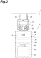
FIG. 2 is a front diagram of an overhead traveling vehicle inFIG. 1 . -
FIG. 3 is a rear view of a main body of the overhead traveling vehicle inFIG. 1 . -
FIG. 4 is a block diagram illustrating a functional configuration of the traveling vehicle system inFIG. 1 . -
FIG. 5 is an illustration for explaining operation of the traveling vehicle system at a branching section. -
FIG. 6 is an illustration for explaining operation of the traveling vehicle system at a merging section. - A preferred embodiment according to an aspect of the present invention will be described in detail below with reference to the drawings . In the description of the drawings, the same elements are denoted by the same reference signs and an overlapping description is omitted.
- A
traveling vehicle system 1 is, for example, a system for transporting an article 10 (seeFIG. 2 ) betweenplacement sections overhead traveling vehicle 6 movable along a track (a predetermined traveling path) 4. Examples of thearticle 10 include containers such as a front opening unified pod (FOUP) storing a plurality of semiconductor wafers and a reticle pod storing a glass substrate, and common parts. Here, for example, thetraveling vehicle system 1 in a factory is taken as an example, in which the overhead traveling vehicle 6 (hereinafter simply referred to as "travelingvehicle 6") travels along the one-way track 4 laid on the ceiling in the factory. As illustrated inFIG. 1 , thetraveling vehicle system 1 includes thetrack 4,mirrors traveling vehicles 6, and a plurality ofplacement sections 9. - As illustrated in
FIG. 2 , thetrack 4 is laid, for example, in the vicinity of the ceiling that is a space above the worker's head. Thetrack 4 is, for example, suspended from the ceiling. Thetrack 4 is a predetermined traveling path for thetraveling vehicles 6 to travel. Thetrack 4 is supported bystruts - As illustrated in
FIG. 1 , themirrors track 4 and reflect a light emitting diode (LED) array (display unit) 55 (seeFIG. 3 ) provided on thetraveling vehicle 6. Thetrack 4 includes abranching section 41 including an incomingpath 41Athat comes into a predetermined location along one direction, a firstoutgoing path 41B that goes out from the predetermined location along the one direction, and a secondoutgoing path 41C that goes out from the predetermined location in a direction different from the one direction. Themirror 45A is arranged near (to the side of) thebranching section 41. Themirror 45A reflects theLED array 55 provided at a drop-preventingcover 33a of a travelingvehicle 6 ahead (front traveling vehicle) as viewed from onetraveling vehicle 6. Thetrack 4 also includes a mergingsection 43 including a firstincoming path 43A that comes into a predetermined location along one direction, a secondincoming path 43B that comes into the predetermined location from a direction different from the one direction, and anoutgoing path 43C that goes out from the predetermined location in a direction different from the one direction. Themirror 45B is arranged near themerging section 43. Themirror 45B reflects theLED array 55 provided at a drop-preventingcover 33b of a travelingvehicle 6 ahead (front traveling vehicle) as viewed from onetraveling vehicle 6. - The
traveling vehicle 6 travels along thetrack 4 and transports thearticle 10. Thetraveling vehicle 6 is configured to transfer thearticle 10. Thetraveling vehicle 6 is an automated overhead transportation vehicle. The number oftraveling vehicles 6 included in thetraveling vehicle system 1 is not limited and is more than one. As illustrated inFIG. 2 andFIG. 3 , thetraveling vehicle 6 includes amain body 7, atraveling unit 18, anLED array 55, an identifier (first identifier and second identifier) 57, animager 8, and acontrol unit 50. - The
main body 7 includes amain body frame 22, atraverse unit 24, aθ drive 26, anelevation driver 28, anelevation stage 30, and a drop-preventingcover 33. The travelingunit 18 includes a motor and allows the travelingvehicle 6 to travel along thetrack 4. The travelingunit 18 includes, for example, a power-receivingcommunication unit 20 that receives power from thetrack 4 via wireless charging. - The
traverse unit 24 allows theθ drive 26, theelevation driver 28, and theelevation stage 30 to collectively traverse in a direction normal to the traveling direction of thetrack 4. The θ drive 26 turns at least one of theelevation driver 28 and theelevation stage 30 within a predetermined angle range in a horizontal plane. Theelevation driver 28 lifts and lowers theelevation stage 30 by reeling or unreeling a hanging member such as wire, rope, and belt. Theelevation stage 30 has a chuck and can grip or release thearticle 10. A pair of drop-preventingcovers 33 are provided, for example, at the front and the rear in the traveling direction of the travelingvehicle 6. The drop-preventingcovers 33 produce a not-illustrated pawl below thearticle 10 to be transported and prevent thearticle 10 from dropping during transportation. - As illustrated in
FIG. 1 andFIG. 2 , theplacement sections 9 are arranged along thetrack 4 and provided at locations where thearticle 10 can be delivered to/from the travelingvehicle 6. Theplacement sections 9 include a buffer and a delivery port. The buffer is a placement section on which thearticle 10 is temporarily placed. The buffer is a placement section on which thearticle 10 is temporarily placed when thearticle 10 transported by the travelingvehicle 6 is unable to be transferred to a target delivery port, for example, for the reason that anotherarticle 10 has been placed on the target delivery port. The delivery port is, for example, a placement section for delivering thearticle 10 to/from a semiconductor processing device (not illustrated) such as a cleaning device, a deposition device, a lithography device, an etching device, a thermal treatment device, and a planarization device. The processing device is not limited to a specific device and may be a variety of devices. - For example, the
placement sections 9 are arranged to the side of thetrack 4. In this case, the travelingvehicle 6 allows thetraverse unit 24 to traverse theelevation driver 28 and the like and slightly lifts and lowers theelevation stage 30 to deliver thearticle 10 to/from theplacement section 9. Although not illustrated, theplacement sections 9 may be arranged immediately below thetrack 4. In this case, the travelingvehicle 6 lifts and lowers theelevation stage 30 to deliver thearticle 10 to/from theplacement section 9. - As illustrated in
FIG. 3 , theLED array 55 is arranged at the drop-preventingcover 33a (33) provided on the rear side of the travelingvehicle 6. TheLED array 55 may be additionally arranged on the drop-preventingcover 33b (33) provided on the front side of the travelingvehicle 6. TheLED array 55 is an LED unit having an array of a plurality of (five)LEDs LED array 55 switches a display manner according to a state of the travelingvehicle 6 itself (the travelingvehicle 6 having the LED array 55). - Specifically, the
LED array 55 changes a display manner with a combination of anilluminated LED 55A and a not-illuminatedLED 55A among fourLEDs 55A (hereinafter simply referred to as "combination of illumination"). The remaining oneLED 55B is used as a parity. That is, it is used to determine whether a combination of illumination of fourLEDs 55A is the display manner intended by thecontrol unit 50. The switching of display manners in theLED array 55 is performed by thecontrol unit 50. - The
identifier 57 is arranged near (adjacent to) theLED array 55. Theidentifier 57 is a predetermined symbol (mark) . Theidentifier 57 may be, for example, a two-dimensional barcode or may include information such as an identification number for identifying each of a plurality of travelingvehicles 6. - The
imager 8 captures an image of theLED array 55 provided on a travelingvehicle 6 located ahead of the travelingvehicle 6 itself. Theimager 8 is arranged on the drop-preventingcover 33b (33) provided on the front side of the travelingvehicle 6. Theimager 8 transmits a captured image obtained by capturing a display manner of theLED array 55 to thecontrol unit 50. As described later, theimager 8 not only captures an image of theLED array 55 provided on a travelingvehicle 6 located ahead of the travelingvehicle 6 itself but also captures an image of theLED array 55 reflected on themirrors track 4. - The
control unit 50 is an electronic control unit including a central processing unit (CPU) , a read only memory (ROM) , and a random access memory (RAM) . Thecontrol unit 50 controls various operations in the travelingvehicle 6. Specifically, as illustrated inFIG. 4 , thecontrol unit 50 controls the travelingunit 18, thetraverse unit 24, theθ drive 26, theelevation driver 28, theelevation stage 30, and theLED array 55. Thecontrol unit 50 can be configured, for example, as software that is a program stored in the ROM, loaded into the RAM, and executed by the CPU. Thecontrol unit 50 may be configured as hardware with electronic circuitry, for example. Thecontrol unit 50 communicates with acontroller 60 using a communication line (feeder line) of thetrack 4. - The
control unit 50 switches a display manner of theLED array 55 according to a traveling state of the travelingvehicle 6 itself. Specifically, for example, when receiving a command from thecontroller 60 and acquiring that the traveling state of the travelingvehicle 6 itself becomes an acceleration state or a deceleration state, thecontrol unit 50 controls illumination of theLEDs 55A in theLED array 55 to attain a display manner corresponding to the acquired traveling state. In other words, thecontrol unit 50 transmits the traveling state of the travelingvehicle 6 itself to a travelingvehicle 6 behind by switching a display manner of theLED array 55 provided on the travelingvehicle 6. Thecontrol unit 50 also switches a display manner of theLED array 55 according to the present location of the travelingvehicle 6 itself. Specifically, thecontrol unit 50, for example, acquires the traveling location of the travelingvehicle 6 itself by reading information such as a barcode attached to thetrack 4 and then controls illumination of theLEDs 55A in theLED array 55 to attain a display manner corresponding to the acquired traveling location. In other words, thecontrol unit 50 transmits the traveling location of the travelingvehicle 6 itself to a travelingvehicle 6 behind by switching a display manner of theLED array 55 provided on the travelingvehicle 6. - The
control unit 50 acquires a state of a travelingvehicle 6 ahead based on the display manner captured by theimager 8 or the display manner captured by theimager 8 through themirrors unit 18 of the travelingvehicle 6 itself based on the acquired state. Specifically, thecontrol unit 50 acquires a state of a travelingvehicle 6 located ahead, based on the manner of theLED array 55 of the travelingvehicle 6 located ahead that is captured by theimager 8. Thecontrol unit 50, for example, extracts a combination of illumination of theLED array 55 from the acquired captured image and refers to combination information in which the states of the travelingvehicle 6 and the combinations of illumination are mapped and stored. Thecontrol unit 50 thus acquires the state of the travelingvehicle 6 ahead. - The
control unit 50 controls the travelingunit 18 in accordance with the acquired state of the travelingvehicle 6 ahead. Specifically, thecontrol unit 50 decelerates the travelingunit 18 of the travelingvehicle 6 itself when acquiring that the traveling state of the travelingvehicle 6 ahead is the decelerated state. Furthermore, thecontrol unit 50 accelerates the travelingunit 18 of the travelingvehicle 6 itself when acquiring that the traveling state of the travelingvehicle 6 ahead is the accelerated state. - The
control unit 50 determines whether to control the travelingunit 18, based on the positional relation between theLED array 55 and theidentifier 57 in the captured image acquired by theimager 8. For example, when theidentifier 57 is recognized at a predetermined position relative to the LED array 55 (for example, the lower left to the LED array 55) in the captured image, thecontrol unit 50 acquires a state of the travelingvehicle 6 ahead from the acquired captured image and controls the travelingunit 18 in accordance with the acquired state. On the other hand, when theidentifier 57 is not recognized at a predetermined position relative to theLED array 55 in the captured image, thecontrol unit 50 does not control the travelingunit 18 based on the acquired captured image. In other words, thecontrol unit 50 determines that the acquired display manner is not the one acquired from theLED array 55 provided on the travelingvehicle 6 ahead, and does not control the travelingunit 18. - The
control unit 50 also determines whether the display manner is a mirror image reflected on themirrors LED array 55 and theidentifier 57 in the captured image acquired by theimager 8. For example, when theidentifier 57 is recognized at a predetermined position relative to the LED array 55 (for example, the lower right to the LED array 55) in the captured image, thecontrol unit 50 determines that it is the captured image (direct image) in which theLED array 55 of the travelingvehicle 6 ahead is directly captured, not through themirrors identifier 57 is not recognized at a predetermined position relative to theLED array 55 in the captured image, thecontrol unit 50 determines that it is the captured image (mirror image) acquired through themirrors control unit 50 thus can determine whether the acquired combination of illumination of theLED array 55 is the one reflected on themirrors - The
controller 60 is an electronic control unit including a central processing unit (CPU) , a read only memory (ROM) , and a random access memory (RAM) . Thecontroller 60 can be configured, for example, as software that is a program stored in the ROM, loaded into the RAM, and executed by the CPU. Thecontroller 60 maybe configured as hardware with electronic circuitry, for example. Thecontroller 60 transmits a transportation command to the travelingvehicle 6 to transport thearticle 10. - The operation of the traveling
vehicle system 1 in the present embodiment will now be described with the following cases as examples: - (1) when the traveling
vehicle 6 ahead decelerates, - (2) when the traveling
vehicle 6 ahead accelerates, - (3) when the traveling
vehicle 6 ahead branches from a branching section, and - (4) when the traveling
vehicle 6 ahead merges into a merging section. - For example, a case where the traveling
vehicle 6 ahead suddenly stops for some reason will be described as an example. The travelingvehicle 6 is monitoring the distance to an obstacle (including a traveling vehicle) ahead, for example, with an obstacle sensor for monitoring a view ahead. In a conventional traveling vehicle system, a traveling vehicle ahead decelerates when the distance to an obstacle ahead is a predetermined distance and stops when the distance to the obstacle ahead is a second predetermined distance shorter than the previous predetermined distance. Similarly, a traveling vehicle behind decelerates when the distance to the traveling vehicle ahead is a predetermined distance and stops when the distance to the traveling vehicle ahead is a second predetermined distance shorter than the predetermined distance. In such a conventional traveling vehicle system, for example, even when the traveling vehicle ahead starts deceleration, the traveling vehicle behind is unable to decelerate until the traveling vehicle behind approaches a predetermined distance. The traveling vehicle behind therefore is unable to start deceleration immediately at the timing when the traveling vehicle ahead starts deceleration. The traveling vehicle behind therefore need to travel with the inter-vehicle distance kept relatively longer in order to avoid collision with the traveling vehicle ahead, leading to reduction in transportation capability. - Compared with such a conventional traveling vehicle system, in the traveling
vehicle system 1 described above, the travelingvehicle 6 ahead decelerates when the distance to the travelingvehicle 6 ahead is a predetermined distance and simultaneously indicates that the state of the travelingvehicle 6 itself is the decelerated state on theLED array 55. The travelingvehicle 6 behind determines a state of the traveling vehicle 6 a head based on the combination of illumination of theLED array 55 that is captured by theimager 8. The travelingvehicle 6 behind then starts deceleration immediately when it is determined that the travelingvehicle 6 ahead becomes the decelerated state. In other words, the travelingvehicle 6 behind can start deceleration immediately at the timing when the travelingvehicle 6 ahead starts deceleration. The travelingvehicle 6 behind therefore only need to keep the minimum inter-vehicle distance for avoiding collision with the travelingvehicle 6 ahead, leading to improvement in transportation capability. - For example, a case where a start command is transmitted from the
controller 60 simultaneously to the travelingvehicle 6 ahead and the travelingvehicle 6 behind will be described as an example. The travelingvehicle 6 is monitoring the distance to an obstacle ahead, for example, with an obstacle sensor for monitoring a view ahead. In such a case, in the conventional traveling vehicle system, first, the traveling vehicle ahead confirms that there is no obstacle using an obstacle sensor or the like and thereafter accelerates (starts) . The traveling vehicle behind accelerates when the distance to the traveling vehicle ahead is equal to or longer than a predetermined distance. In such a conventional traveling vehicle system, the traveling vehicle behind is unable to start acceleration immediately at the timing when the traveling vehicle ahead starts acceleration, for example, because although the travelingvehicle 6 ahead accelerates, there is a waiting time until the travelingvehicle 6 ahead moves away to a predetermined distance from the traveling vehicle behind. The operating rate of the traveling vehicle behind therefore decreases by the waiting time, leading to reduction in transportation capability. - Compared with such a conventional traveling vehicle system, in the traveling vehicle system described above, the traveling
vehicle 6 ahead indicates that the state of the travelingvehicle 6 itself is the accelerated state on theLED array 55, simultaneously when starting acceleration. The travelingvehicle 6 behind determines a state of the travelingvehicle 6 ahead based on the combination of illumination ofLED array 55 that is captured by theimager 8. The travelingvehicle 6 behind then starts acceleration immediately when it is determined that the travelingvehicle 6 ahead becomes the accelerated state. In other words, the travelingvehicle 6 behind can start acceleration immediately at the timing when the travelingvehicle 6 ahead starts acceleration. The operating rate of the traveling vehicle behind therefore can be increased, leading to improvement in transportation capability. - For example, as illustrated in
FIG. 5 , a case where the travelingvehicle 6 ahead takes the secondoutgoing path 41C and the travelingvehicle 6 behind is due to take the firstoutgoing path 41B at the branchingsection 41 will be described as an example. The travelingvehicle 6 is monitoring the distance to an obstacle ahead, for example, with an obstacle sensor for monitoring a view ahead. Such an obstacle sensor often detects the travelingvehicle 6 ahead even when the traveling vehicle entering the secondoutgoing path 41C is located at a place where it does not collide with the travelingvehicle 6 behind entering the first out goingpath 41B. In the conventional method that controls whether to permit entry at the branchingsection 41 based on the presence or absence of detection by the obstacle sensor, entry of the travelingvehicle 6 behind into the branchingsection 41 is restricted as a consequence, leading to reduction in transportation capability. - Compared with such a conventional traveling vehicle system, in the traveling
vehicle system 1 described above, the travelingvehicle 6 ahead acquires the location in thetrack 4 from a barcode (barcode indicates the location) affixed along thetrack 4 and indicates the acquired barcode information on theLED array 55. The travelingvehicle 6 behind acquires the location of the travelingvehicle 6 ahead based on the combination of illumination of theLED array 55 that is captured by theimager 8. However, it is difficult for theimager 8 provided at the drop-preventingcover 33a on the front side of the travelingvehicle 6 behind to capture an image of theLED array 55 of the travelingvehicle 6 ahead that deviates to the side. - Then, in the traveling
vehicle system 1 described above, theimager 8 of the travelingvehicle 6 behind captures an image of theLED array 55 of the travelingvehicle 6 ahead that is reflected on themirror 45A provided at the branchingsection 41. The travelingvehicle 6 behind acquires the location of the travelingvehicle 6 ahead based on the combination of illumination of theLED array 55 that is captured by theimager 8. The travelingvehicle 6 behind can enter the branchingsection 41 at the point of time when it is determined that the travelingvehicle 6 ahead has moved to a location where it does not collide with the travelingvehicle 6 behind. The unnecessary waiting time otherwise caused at the branchingsection 41 therefore can be eliminated, thereby increasing the operating rate and leading to improvement in transportation capability. - For example, as illustrated in
FIG. 6 , a case where the travelingvehicle 6 ahead takes the firstincoming path 43A and the travelingvehicle 6 behind takes the secondincoming path 43B at the mergingsection 43 will be described as an example. The travelingvehicle 6 is monitoring the distance to an obstacle ahead, for example, with an obstacle sensor for monitoring a view ahead. Even when the travelingvehicle 6 in the firstincoming path 43A stops at a location where it does not collide with the travelingvehicle 6 entering from the secondincoming path 43B, the obstacle sensor provided on the travelingvehicle 6 entering from the secondincoming path 43B often detects the traveling vehicle stopping at the firstincoming path 43A as the travelingvehicle 6 ahead. In the conventional method that controls whether to permit entry at the mergingsection 43 based on the presence or absence of detection by the obstacle sensor, entry of the travelingvehicle 6 behind into the mergingsection 43 is restricted as a consequence, leading to reduction in transportation capability. - Compared with such a conventional traveling vehicle system, in the traveling
vehicle system 1 described above, the travelingvehicle 6 ahead acquires the location in thetrack 4 from a barcode affixed along thetrack 4 and indicates the acquiredbarcode information on theLED array 55. The travelingvehicle 6 behind acquires the location of the travelingvehicle 6 ahead based on the combination of illumination of theLED array 55 that is captured by theimager 8. However, it is difficult for theimager 8 provided at the drop-preventingcover 33a on the front side of the travelingvehicle 6 behind to capture an image of theLED array 55 of the travelingvehicle 6 ahead of the travelingvehicle 6 behind entering from the side. - Then, in the traveling
vehicle system 1 described above, theimager 8 of the travelingvehicle 6 behind captures an image of theLED array 55 provided at the drop-preventingcover 33a on the front side of the travelingvehicle 6 ahead that is reflected on themirror 45B provided at the mergingsection 43. The travelingvehicle 6 behind acquires the location of the travelingvehicle 6 ahead based on the combination of illumination of theLED array 55 that is captured by theimager 8. The travelingvehicle 6 behind can enter the mergingsection 43 when it is determined that the travelingvehicle 6 ahead is stopping at a location where it does not collide with the travelingvehicle 6 behind. The unnecessary waiting time otherwise caused at the mergingsection 43 can be eliminated, thereby increasing the operating rate and leading to improvement in transportation capability. - A state of the traveling
vehicle 6 ahead may be acquired through theLED array 55 by a method using wireless radio waves, a method using infrared communication, and a method using wireless feeder. However, the method in the present embodiment is advantageous over the method using wireless radio waves in that communication failure is less likely to occur and communication failure due to change in communication environment over time is less likely to occur. The method in the present embodiment is also advantageous over the method using infrared communication in that it is immune to deviation of the optical axis. The method in the present embodiment is also advantageous over the method using wireless feeder in that a signal transmission response is fast (latency is short). - A 3D sensor may be arranged instead of the method of acquiring the location of the traveling
vehicle 6 by acquiring the display manner of theLED array 55 provided on the travelingvehicle 6 ahead through themirrors imager 8. However, compared with the method using a 3D sensor, the method in the present embodiment can reduce the possibility that the travelingvehicle 6 ahead is hidden behind a structure (rack, post, etc.) and becomes out of sight. - The operation effect of the traveling
vehicle system 1 in the foregoing embodiment will now be described. In the travelingvehicle 6 and the travelingvehicle system 1 in the foregoing embodiment, since a display manner that varies according to a state of the traveling vehicle 6 (a display manner according to a state of the traveling vehicle 6) is indicated on theLED array 55, the travelingvehicle 6 behind that acquires the display manner of theLED array 55 with theimager 8 can determine a state of the travelingvehicle 6 ahead instantaneously. With this configuration, the travelingvehicle 6 behind can promptly perform operation appropriate for the state of the travelingvehicle 6 ahead. - The traveling
vehicle 6 and the travelingvehicle system 1 in the foregoing embodiment enables the travelingvehicle 6 behind to grasp whether the travelingvehicle 6 itself is in the accelerated state or the decelerated state. With this configuration, when the travelingvehicle 6 ahead accelerates, the travelingvehicle 6 behind can promptly follow the acceleration, and when the travelingvehicle 6 ahead decelerates, the travelingvehicle 6 behind can promptly follow the deceleration. - The traveling
vehicle 6 and the travelingvehicle system 1 in the foregoing embodiment enables the travelingvehicle 6 behind to grasp the traveling location of the travelingvehicle 6 itself. With this configuration, the travelingvehicle 6 behind can accurately grasp the positional relation to the travelingvehicle 6 ahead. As a result, for example, the distance to the travelingvehicle 6 ahead can be acquired with high precision, or when the travelingvehicle 6 behindmoves, the travelingvehicle 6 can determine with high precision that it will not collide with the travelingvehicle 6 ahead. - In the traveling
vehicle 6 and the travelingvehicle system 1 in the foregoing embodiment, thecontrol unit 50 acquires a state of the travelingvehicle 6 ahead, based on the display manner captured by theimager 8 and the positional relation between theLED array 55 and theidentifier 57. With this configuration, for example, the possibility that an unintended LED array (not provided on the traveling vehicle 6) is recognized by error can be reduced. When theidentifier 57 is arranged at a position shifted from the center in the array direction of theLEDs 55A in theLED array 55, it can be determined whether the captured image captured by theimager 8 is a mirror image. Thus, the number of display manners can be increased with a simple configuration. - In the traveling
vehicle system 1 in the foregoing embodiment, since each individual travelingvehicle 6 can promptly perform operation appropriate for the state of the travelingvehicle 6 ahead, the transportation performance of the travelingvehicle system 1 as a whole can be increased. - In the traveling
vehicle system 1 in the foregoing embodiment, since themirrors mirrors vehicle 6 ahead is located beyond a curve section as viewed from the travelingvehicle 6 behind, and the range of visibility of the travelingvehicle 6 ahead is narrow. - Although an embodiment of an aspect of the present invention has been described above, an aspect of the present invention is not limited to the foregoing embodiment and susceptible to various modifications without departing from the scope of the claims.
- In the foregoing embodiment, an example in which the
LED array 55 is employed as the display unit that switches a display manner according to the state of the traveling vehicle itself has been described. However, the present invention is not limited thereto. For example, a liquid crystal display screen may be employed, and display contents (color, pattern, symbol, character, etc.) may be changed according to the state of the traveling vehicle itself. Alternatively, an illumination device that simply switches colors to be displayed (emitted) may be employed. - In the foregoing embodiment and modifications, an example in which a display manner corresponding to the location of the traveling
vehicle 6 is reflected on the mirrors 54A and 54B has been described. However, for example, a display manner corresponding to the traveling state (the accelerated state and the decelerated state) of the travelingvehicle 6 may be reflected through communication means. An example in which the mirrors 54A and 54B are installed at the branchingsection 41 and the mergingsection 43 has been described. However, they may be installed, for example, at a curve section. Also in this case, the range in which the travelingvehicle 6 ahead is visible can be widened. - In the foregoing embodiment and modifications, an example in which the
control unit 50 controlling the travelingvehicle 6 is provided in themain body 7 of each individual travelingvehicle 6 has been described. However, thecontrol unit 50 may be separate from themain body 7 and arranged at a location where it can communicate by wire or by radio . In such a case, thecontrol unit 50 may be provided as a control unit that collectively controls a plurality of travelingvehicles 6, rather than being provided corresponding to each of a plurality of travelingvehicles 6. Thecontrol unit 50 then may control the display unit (for example, the LED array 55) provided for each individual travelingvehicle 6 so as to switch a display manner of each display unit according to the state (for example, traveling state) of the corresponding travelingvehicle 6. - In the traveling
vehicle system 1 in the foregoing embodiment and modifications, overhead traveling vehicles have been described as an example of the traveling vehicles. However, other examples of the traveling vehicles include unmanned traveling vehicles and stacker cranes traveling on a track installed on the ground or a rack. - 1 ... traveling vehicle system, 4 ... track, 6 ... overhead traveling vehicle (traveling vehicle), 7 ... main body, 8 ... imager, 9 ... placement section, 18 ... travelingunit, 41 ... branching section, 43 ... merging section, 45A, 45B ... mirror, 50 ... control unit, 55 ... LED array, 57 ... identifier, 60 ... controller.
Claims (6)
- A traveling vehicle that travels along a predetermined traveling path, comprising:a main body;a traveling unit configured to allow the main body to travel along the traveling path;a display unit disposed at the main body and configured to switch a display manner according to a state of the traveling vehicle itself;an imager configured to capture an image of the display unit provided at a front traveling vehicle located ahead of the traveling vehicle itself; anda control unit configured to acquire a state of the front traveling vehicle based on the display manner captured by the imager, and to control the traveling unit of the traveling vehicle itself based on the acquired state.
- The traveling vehicle according to claim 1, whereinthe display unit switches the display manner according to a traveling state of the traveling vehicle itself, andthe traveling state includes an accelerated state and a decelerated state.
- The traveling vehicle according to claim 1 or 2, wherein the display switches the display manner according to a present location of the traveling vehicle itself.
- The traveling vehicle according to any one of claims 1 to 3, whereinthe traveling vehicle further includes an identifier disposed near the display unit, andthe control unit acquires a state of the front traveling vehicle based on the display manner captured by the imager and a positional relation between the display unit and the identifier, and controls the traveling unit of the traveling vehicle itself based on the acquired state.
- A traveling vehicle system comprising a plurality of the traveling vehicles according to any one of claims 1 to 4.
- The traveling vehicle system according to claim 5, further comprising a mirror disposed along the traveling path and configured to reflect the display unit disposed at the front traveling vehicle, wherein
the control unit acquires a state of the front traveling vehicle based on the display manner captured by the imager through the mirror.
Applications Claiming Priority (2)
| Application Number | Priority Date | Filing Date | Title |
|---|---|---|---|
| JP2019031996 | 2019-02-25 | ||
| PCT/JP2019/048812 WO2020174812A1 (en) | 2019-02-25 | 2019-12-12 | Traveling vehicle and traveling vehicle system |
Publications (2)
| Publication Number | Publication Date |
|---|---|
| EP3933536A1 true EP3933536A1 (en) | 2022-01-05 |
| EP3933536A4 EP3933536A4 (en) | 2022-11-02 |
Family
ID=72238302
Family Applications (1)
| Application Number | Title | Priority Date | Filing Date |
|---|---|---|---|
| EP19917218.0A Pending EP3933536A4 (en) | 2019-02-25 | 2019-12-12 | MOVING VEHICLE AND MOVING VEHICLE SYSTEM |
Country Status (7)
| Country | Link |
|---|---|
| US (1) | US11904887B2 (en) |
| EP (1) | EP3933536A4 (en) |
| JP (1) | JP7151863B2 (en) |
| CN (1) | CN113439248B (en) |
| SG (1) | SG11202108889VA (en) |
| TW (1) | TWI834818B (en) |
| WO (1) | WO2020174812A1 (en) |
Families Citing this family (4)
| Publication number | Priority date | Publication date | Assignee | Title |
|---|---|---|---|---|
| JP7568079B2 (en) * | 2021-05-07 | 2024-10-16 | 村田機械株式会社 | Vehicle and vehicle system |
| US20230214551A1 (en) * | 2021-12-30 | 2023-07-06 | Semes Co., Ltd. | Virtual driving system and its control method |
| WO2024202679A1 (en) * | 2023-03-28 | 2024-10-03 | 村田機械株式会社 | Traveling vehicle and traveling vehicle system |
| JP2025116601A (en) * | 2024-01-29 | 2025-08-08 | 株式会社ダイフク | Conveying Equipment |
Family Cites Families (18)
| Publication number | Priority date | Publication date | Assignee | Title |
|---|---|---|---|---|
| JPH0685135B2 (en) * | 1987-04-16 | 1994-10-26 | 株式会社ダイフク | Driving control method for preventing rear-end collision of self-propelled vehicle |
| JPH03131911A (en) * | 1989-10-18 | 1991-06-05 | Murata Mach Ltd | Method for preventing generation of collision on curve of unmanned carrier system |
| JPH05173629A (en) * | 1991-12-25 | 1993-07-13 | Ishikawajima Shibaura Mach Co Ltd | Unmanned vehicle visual device |
| JP2001202497A (en) * | 2000-01-18 | 2001-07-27 | Toyota Motor Corp | Vehicle detection system and method |
| JP2001249718A (en) | 2000-03-03 | 2001-09-14 | Shinko Electric Co Ltd | Collision prevention device for transport vehicles in rail transport devices |
| JP4399739B2 (en) | 2005-07-12 | 2010-01-20 | 村田機械株式会社 | Conveyor cart system |
| WO2009142051A1 (en) * | 2008-05-22 | 2009-11-26 | 村田機械株式会社 | Traveling vehicle system and method for controlling traveling by traveling vehicle system |
| JP2012256235A (en) | 2011-06-09 | 2012-12-27 | Mitsubishi Electric Corp | Information providing device for driving support, on-vehicle driving support device and driving support system |
| CA2923683C (en) * | 2013-12-12 | 2018-03-13 | Hitachi Construction Machinery Co., Ltd. | Vehicle travel system and vehicle travel control method |
| JP2016218736A (en) * | 2015-05-20 | 2016-12-22 | 株式会社豊田自動織機 | Unmanned conveyance system |
| EP3385675A4 (en) * | 2016-03-28 | 2018-12-19 | Aisin Aw Co., Ltd. | Communication terminal, server device, movement guidance system, and computer program |
| KR101866728B1 (en) * | 2016-04-25 | 2018-06-15 | 현대자동차주식회사 | Navigation apparatus, vehicle and method for controlling vehicle |
| JP6390035B2 (en) * | 2016-05-23 | 2018-09-19 | 本田技研工業株式会社 | Vehicle control system, vehicle control method, and vehicle control program |
| US10331142B2 (en) * | 2016-09-18 | 2019-06-25 | Eyedog Israel Ltd. | Monitoring of vehicle passing maneuver |
| JP6880784B2 (en) * | 2017-01-30 | 2021-06-02 | 村田機械株式会社 | Bogie system |
| JP2018136844A (en) * | 2017-02-23 | 2018-08-30 | 株式会社ダイフク | Article conveyance vehicle |
| JP2018163415A (en) * | 2017-03-24 | 2018-10-18 | 株式会社日立製作所 | Transport system, transport method, and automatic transport vehicle |
| US20210016793A1 (en) * | 2018-03-28 | 2021-01-21 | Hiroshi Yamaguchi | Control apparatus, display apparatus, movable body, and image display method |
-
2019
- 2019-12-12 US US17/431,445 patent/US11904887B2/en active Active
- 2019-12-12 WO PCT/JP2019/048812 patent/WO2020174812A1/en not_active Ceased
- 2019-12-12 CN CN201980092195.8A patent/CN113439248B/en active Active
- 2019-12-12 JP JP2021501606A patent/JP7151863B2/en active Active
- 2019-12-12 SG SG11202108889VA patent/SG11202108889VA/en unknown
- 2019-12-12 EP EP19917218.0A patent/EP3933536A4/en active Pending
-
2020
- 2020-02-21 TW TW109105681A patent/TWI834818B/en active
Also Published As
| Publication number | Publication date |
|---|---|
| CN113439248B (en) | 2024-04-19 |
| JP7151863B2 (en) | 2022-10-12 |
| CN113439248A (en) | 2021-09-24 |
| WO2020174812A1 (en) | 2020-09-03 |
| JPWO2020174812A1 (en) | 2021-12-23 |
| EP3933536A4 (en) | 2022-11-02 |
| TW202036193A (en) | 2020-10-01 |
| US11904887B2 (en) | 2024-02-20 |
| TWI834818B (en) | 2024-03-11 |
| SG11202108889VA (en) | 2021-09-29 |
| US20220135066A1 (en) | 2022-05-05 |
Similar Documents
| Publication | Publication Date | Title |
|---|---|---|
| US11904887B2 (en) | Traveling vehicle and traveling vehicle system | |
| US9758308B1 (en) | Article transport facility | |
| US9932175B2 (en) | Article transport facility | |
| US9658239B2 (en) | Laboratory product transport element and path arrangement | |
| US11001259B2 (en) | Transport system | |
| US12588468B2 (en) | Overhead transport vehicle | |
| US12534296B2 (en) | Traveling vehicle system and traveling vehicle control method | |
| CN114072319B (en) | Traveling vehicle, traveling vehicle system | |
| US12286144B2 (en) | Travelling vehicle and travelling vehicle system | |
| US12518626B2 (en) | Traveling vehicle system | |
| EP4336299B1 (en) | Traveling vehicle and traveling vehicle system | |
| US12528645B2 (en) | Traveling vehicle system and traveling vehicle | |
| JP2018097406A (en) | Traveling vehicle system and traveling vehicle | |
| WO2024150503A1 (en) | Traveling vehicle and traveling vehicle system | |
| WO2024202679A1 (en) | Traveling vehicle and traveling vehicle system |
Legal Events
| Date | Code | Title | Description |
|---|---|---|---|
| STAA | Information on the status of an ep patent application or granted ep patent |
Free format text: STATUS: THE INTERNATIONAL PUBLICATION HAS BEEN MADE |
|
| PUAI | Public reference made under article 153(3) epc to a published international application that has entered the european phase |
Free format text: ORIGINAL CODE: 0009012 |
|
| STAA | Information on the status of an ep patent application or granted ep patent |
Free format text: STATUS: REQUEST FOR EXAMINATION WAS MADE |
|
| 17P | Request for examination filed |
Effective date: 20210825 |
|
| AK | Designated contracting states |
Kind code of ref document: A1 Designated state(s): AL AT BE BG CH CY CZ DE DK EE ES FI FR GB GR HR HU IE IS IT LI LT LU LV MC MK MT NL NO PL PT RO RS SE SI SK SM TR |
|
| DAV | Request for validation of the european patent (deleted) | ||
| DAX | Request for extension of the european patent (deleted) | ||
| A4 | Supplementary search report drawn up and despatched |
Effective date: 20221006 |
|
| RIC1 | Information provided on ipc code assigned before grant |
Ipc: H01L 21/677 20060101ALI20220929BHEP Ipc: H01L 21/67 20060101ALI20220929BHEP Ipc: G05D 1/02 20200101AFI20220929BHEP |
|
| STAA | Information on the status of an ep patent application or granted ep patent |
Free format text: STATUS: EXAMINATION IS IN PROGRESS |
|
| 17Q | First examination report despatched |
Effective date: 20260202 |