EP3933518A1 - A communication system and method for industrial automation - Google Patents
A communication system and method for industrial automation Download PDFInfo
- Publication number
- EP3933518A1 EP3933518A1 EP20183107.0A EP20183107A EP3933518A1 EP 3933518 A1 EP3933518 A1 EP 3933518A1 EP 20183107 A EP20183107 A EP 20183107A EP 3933518 A1 EP3933518 A1 EP 3933518A1
- Authority
- EP
- European Patent Office
- Prior art keywords
- operational information
- gateway device
- industrial automation
- industrial
- automation device
- Prior art date
- Legal status (The legal status is an assumption and is not a legal conclusion. Google has not performed a legal analysis and makes no representation as to the accuracy of the status listed.)
- Withdrawn
Links
- 238000000034 method Methods 0.000 title claims abstract description 24
- 238000004891 communication Methods 0.000 title description 14
- 238000004590 computer program Methods 0.000 claims description 6
- 238000005070 sampling Methods 0.000 claims description 6
- 238000005259 measurement Methods 0.000 abstract description 6
- 230000015654 memory Effects 0.000 description 32
- 241000196324 Embryophyta Species 0.000 description 6
- 230000006870 function Effects 0.000 description 6
- 238000005516 engineering process Methods 0.000 description 5
- 238000004519 manufacturing process Methods 0.000 description 4
- 238000012545 processing Methods 0.000 description 4
- 230000001413 cellular effect Effects 0.000 description 3
- 238000010586 diagram Methods 0.000 description 2
- 230000014509 gene expression Effects 0.000 description 2
- 230000006698 induction Effects 0.000 description 2
- 239000004973 liquid crystal related substance Substances 0.000 description 2
- 230000003287 optical effect Effects 0.000 description 2
- 238000013021 overheating Methods 0.000 description 2
- 230000011664 signaling Effects 0.000 description 2
- 238000012546 transfer Methods 0.000 description 2
- 241000202567 Fatsia japonica Species 0.000 description 1
- 238000003491 array Methods 0.000 description 1
- 230000005540 biological transmission Effects 0.000 description 1
- 230000010267 cellular communication Effects 0.000 description 1
- 238000012993 chemical processing Methods 0.000 description 1
- 238000013500 data storage Methods 0.000 description 1
- 230000003247 decreasing effect Effects 0.000 description 1
- 238000001514 detection method Methods 0.000 description 1
- 238000001914 filtration Methods 0.000 description 1
- 229910052500 inorganic mineral Inorganic materials 0.000 description 1
- 230000005415 magnetization Effects 0.000 description 1
- 239000011707 mineral Substances 0.000 description 1
- 238000005065 mining Methods 0.000 description 1
- 238000012544 monitoring process Methods 0.000 description 1
- 230000006855 networking Effects 0.000 description 1
- 239000003921 oil Substances 0.000 description 1
- 238000009877 rendering Methods 0.000 description 1
- 239000004065 semiconductor Substances 0.000 description 1
- 229910052710 silicon Inorganic materials 0.000 description 1
- 239000010703 silicon Substances 0.000 description 1
- 239000007858 starting material Substances 0.000 description 1
- 230000000007 visual effect Effects 0.000 description 1
Images


Classifications
-
- G—PHYSICS
- G05—CONTROLLING; REGULATING
- G05B—CONTROL OR REGULATING SYSTEMS IN GENERAL; FUNCTIONAL ELEMENTS OF SUCH SYSTEMS; MONITORING OR TESTING ARRANGEMENTS FOR SUCH SYSTEMS OR ELEMENTS
- G05B19/00—Programme-control systems
- G05B19/02—Programme-control systems electric
- G05B19/04—Programme control other than numerical control, i.e. in sequence controllers or logic controllers
- G05B19/042—Programme control other than numerical control, i.e. in sequence controllers or logic controllers using digital processors
- G05B19/0428—Safety, monitoring
-
- G—PHYSICS
- G05—CONTROLLING; REGULATING
- G05B—CONTROL OR REGULATING SYSTEMS IN GENERAL; FUNCTIONAL ELEMENTS OF SUCH SYSTEMS; MONITORING OR TESTING ARRANGEMENTS FOR SUCH SYSTEMS OR ELEMENTS
- G05B19/00—Programme-control systems
- G05B19/02—Programme-control systems electric
- G05B19/18—Numerical control [NC], i.e. automatically operating machines, in particular machine tools, e.g. in a manufacturing environment, so as to execute positioning, movement or co-ordinated operations by means of programme data in numerical form
- G05B19/4155—Numerical control [NC], i.e. automatically operating machines, in particular machine tools, e.g. in a manufacturing environment, so as to execute positioning, movement or co-ordinated operations by means of programme data in numerical form characterised by programme execution, i.e. part programme or machine function execution, e.g. selection of a programme
-
- G—PHYSICS
- G05—CONTROLLING; REGULATING
- G05B—CONTROL OR REGULATING SYSTEMS IN GENERAL; FUNCTIONAL ELEMENTS OF SUCH SYSTEMS; MONITORING OR TESTING ARRANGEMENTS FOR SUCH SYSTEMS OR ELEMENTS
- G05B23/00—Testing or monitoring of control systems or parts thereof
- G05B23/02—Electric testing or monitoring
- G05B23/0205—Electric testing or monitoring by means of a monitoring system capable of detecting and responding to faults
- G05B23/0208—Electric testing or monitoring by means of a monitoring system capable of detecting and responding to faults characterized by the configuration of the monitoring system
-
- H—ELECTRICITY
- H04—ELECTRIC COMMUNICATION TECHNIQUE
- H04L—TRANSMISSION OF DIGITAL INFORMATION, e.g. TELEGRAPHIC COMMUNICATION
- H04L12/00—Data switching networks
- H04L12/66—Arrangements for connecting between networks having differing types of switching systems, e.g. gateways
-
- H—ELECTRICITY
- H04—ELECTRIC COMMUNICATION TECHNIQUE
- H04L—TRANSMISSION OF DIGITAL INFORMATION, e.g. TELEGRAPHIC COMMUNICATION
- H04L67/00—Network arrangements or protocols for supporting network services or applications
- H04L67/01—Protocols
- H04L67/12—Protocols specially adapted for proprietary or special-purpose networking environments, e.g. medical networks, sensor networks, networks in vehicles or remote metering networks
-
- G—PHYSICS
- G05—CONTROLLING; REGULATING
- G05B—CONTROL OR REGULATING SYSTEMS IN GENERAL; FUNCTIONAL ELEMENTS OF SUCH SYSTEMS; MONITORING OR TESTING ARRANGEMENTS FOR SUCH SYSTEMS OR ELEMENTS
- G05B2219/00—Program-control systems
- G05B2219/20—Pc systems
- G05B2219/25—Pc structure of the system
- G05B2219/25132—Superposition data signals on power lines for actuators
-
- G—PHYSICS
- G05—CONTROLLING; REGULATING
- G05B—CONTROL OR REGULATING SYSTEMS IN GENERAL; FUNCTIONAL ELEMENTS OF SUCH SYSTEMS; MONITORING OR TESTING ARRANGEMENTS FOR SUCH SYSTEMS OR ELEMENTS
- G05B2219/00—Program-control systems
- G05B2219/20—Pc systems
- G05B2219/25—Pc structure of the system
- G05B2219/25188—Superposition high frequency data signal on power lines, current carrier
-
- G—PHYSICS
- G05—CONTROLLING; REGULATING
- G05B—CONTROL OR REGULATING SYSTEMS IN GENERAL; FUNCTIONAL ELEMENTS OF SUCH SYSTEMS; MONITORING OR TESTING ARRANGEMENTS FOR SUCH SYSTEMS OR ELEMENTS
- G05B2219/00—Program-control systems
- G05B2219/20—Pc systems
- G05B2219/25—Pc structure of the system
- G05B2219/25198—Brouter: transfers data from wireless to wired networks, router: wired to wired
-
- G—PHYSICS
- G05—CONTROLLING; REGULATING
- G05B—CONTROL OR REGULATING SYSTEMS IN GENERAL; FUNCTIONAL ELEMENTS OF SUCH SYSTEMS; MONITORING OR TESTING ARRANGEMENTS FOR SUCH SYSTEMS OR ELEMENTS
- G05B2219/00—Program-control systems
- G05B2219/30—Nc systems
- G05B2219/31—From computer integrated manufacturing till monitoring
- G05B2219/31368—MAP manufacturing automation protocol
-
- H—ELECTRICITY
- H04—ELECTRIC COMMUNICATION TECHNIQUE
- H04W—WIRELESS COMMUNICATION NETWORKS
- H04W88/00—Devices specially adapted for wireless communication networks, e.g. terminals, base stations or access point devices
- H04W88/16—Gateway arrangements
-
- Y—GENERAL TAGGING OF NEW TECHNOLOGICAL DEVELOPMENTS; GENERAL TAGGING OF CROSS-SECTIONAL TECHNOLOGIES SPANNING OVER SEVERAL SECTIONS OF THE IPC; TECHNICAL SUBJECTS COVERED BY FORMER USPC CROSS-REFERENCE ART COLLECTIONS [XRACs] AND DIGESTS
- Y04—INFORMATION OR COMMUNICATION TECHNOLOGIES HAVING AN IMPACT ON OTHER TECHNOLOGY AREAS
- Y04S—SYSTEMS INTEGRATING TECHNOLOGIES RELATED TO POWER NETWORK OPERATION, COMMUNICATION OR INFORMATION TECHNOLOGIES FOR IMPROVING THE ELECTRICAL POWER GENERATION, TRANSMISSION, DISTRIBUTION, MANAGEMENT OR USAGE, i.e. SMART GRIDS
- Y04S40/00—Systems for electrical power generation, transmission, distribution or end-user application management characterised by the use of communication or information technologies, or communication or information technology specific aspects supporting them
- Y04S40/12—Systems for electrical power generation, transmission, distribution or end-user application management characterised by the use of communication or information technologies, or communication or information technology specific aspects supporting them characterised by data transport means between the monitoring, controlling or managing units and monitored, controlled or operated electrical equipment
Definitions
- Various exemplary embodiments relate to a communication system, and particularly to a communication system for industrial automation.
- an industrial automation device for example a variable speed drive
- an industrial asset for example a motor that the industrial automation device is controlling.
- a data connection between the industrial automation device and the industrial asset may be required in order to transmit sensor measurements from the industrial asset to the industrial automation device. It is desirable to improve the reliability of data connectivity between an industrial automation device and an industrial asset that are located far away from each other in an industrial plant.
- a method comprising measuring, by a sensor device, operational information associated with an industrial asset; transmitting, by the sensor device, the operational information to a first gateway device via a first wireless connection; receiving, by the first gateway device, the operational information via the first wireless connection; transmitting, by the first gateway device, the operational information to a second gateway device via a wired connection; receiving, by the second gateway device, the operational information via the wired connection; transmitting, by the second gateway device, the operational information to an industrial automation device via a second wireless connection; and receiving, by the industrial automation device, the operational information via the second wireless connection.
- equipment comprising means for implementing the aforementioned method.
- a computer program comprising instructions for causing an apparatus to carry out the aforementioned method.
- a computer readable medium comprising program instructions for causing an apparatus to carry out the aforementioned method.
- a non-transitory computer readable medium comprising program instructions for causing an apparatus to carry out the aforementioned method.
- Various exemplary embodiments may be applicable to any process in an industrial plant, including a processing system and/or an industrial manufacturing related process and/or a system for a technical process, which is at least partly automated, providing different measured/sensored values for a plurality of variables on one or more devices (equipment) and/or on one or more processes.
- a non-limiting list of examples includes power plants, pulp and paper plants, manufacturing plants, chemical processing plants, power transmission systems, mining and mineral processing plants, oil and gas systems, data centers, ships, and transportation fleet systems.
- Virtualization may allow a single physical computing device to host one or more instances of virtual machines that appear and operate as independent computing devices, so that a single physical computing device can create, maintain, delete, or otherwise manage virtual machines in a dynamic manner. It is also possible that device operations will be distributed among a plurality of servers, nodes, devices or hosts. In cloud computing network devices, computing devices and/or storage devices provide shared resources. Some other technology advancements, such as Software-Defined Networking (SDN) may cause one or more of the functionalities described below to be migrated to any corresponding abstraction or apparatus or device. Therefore, all words and expressions should be interpreted broadly, and they are intended to illustrate, not to restrict, the exemplary embodiments.
- SDN Software-Defined Networking
- an industrial automation device for example a variable speed drive
- an industrial asset for example a motor that the industrial automation device is controlling.
- the industrial automation device and the industrial asset may be located over 100 meters or even over 500 meters away from each other.
- a data connection between the industrial automation device and the industrial asset may be required in order to transmit sensor measurements from the industrial asset to the industrial automation device.
- wireless communications such as Bluetooth or Wi-Fi
- a wireless data connection between the industrial automation device and the industrial asset may not be reliable.
- a wireless signal may experience attenuation caused by, for example, concrete and/or other structural elements between the industrial automation device and the industrial asset.
- some exemplary embodiments provide a data connection between an industrial automation device and a sensor device by using both wireless connectivity and an existing cable, for example a power cable or a PtlOO cable, between the industrial automation device and the industrial asset.
- FIG. 1 illustrates a system according to an exemplary embodiment. It should be noted that FIG. 1 illustrates a simplified system architecture only showing some elements and functional entities, all being logical units whose implementation may differ from what is shown. The connections shown in FIG. 1 are logical connections; the actual physical connections may be different. It is apparent to a person skilled in the art that the systems also comprise other functions and structures. It should be appreciated that the functions, structures, elements, and protocols used in or for communication are irrelevant to the exemplary embodiments. Therefore, they need not be discussed in more detail here.
- the system comprises one or more sensor devices 101.
- the sensor device 101 for example a smart sensor or an intelligent sensor, may be a condition monitoring sensor that may be attached to, or comprised in, an industrial asset, i.e. machinery.
- the industrial asset may comprise for example a motor, such as an induction motor, a pump, such as an electric pump, a fan, a compressor, an extruder, and/or a mounted bearing.
- the sensor device 101 may be configured to measure operational information, for example observed technical performance information such as measured values for temperature and/or vibration associated with the industrial asset.
- the sensor device 101 may measure, for example, operational information associated with the motor, fan, compressor, extruder, or mounted bearing comprised in the industrial asset.
- the sensor device 101 may be configured to store the measured operational information for example in an internal memory of the sensor device 101.
- the sensor device 101 may be able to connect to the internet for example via a cellular or wireless link, and the sensor device may be further configured to store the operational information for example to a cloud server.
- the sensor device 101 may be equipped with a short-range radio interface, for example Bluetooth, Wi-Fi, or a wireless mesh protocol.
- the sensor device 101 may be further configured to exchange information, i.e. to transmit and/or receive data, with a first gateway device 102 via a first wireless connection 110, for example a Bluetooth or Wi-Fi connection.
- the sensor device 101 may be configured transmit the measured operational information to the first gateway device 102 via the first wireless connection 110.
- the sensor device 101 may be further configured to analyze the operational information, for example to detect and/or predict a fault associated with the industrial asset, and to transmit a warning if a fault is detected or predicted. For example, a fault may be detected if a measured value, such as temperature, associated with the industrial asset exceeds a predetermined threshold value.
- the first gateway device 102 may comprise for example a Bluetooth gateway, an access point, a server computer or a terminal device, such as a smartphone, a desktop computer, a laptop computer or a tablet computer.
- the first gateway device 102 may be attached to the industrial asset, or located at a close proximity to the sensor device 101, for example less than 10 meters away from the sensor device 101, depending on the range of the wireless technology used by the gateway.
- the first gateway device 102 may be comprised in a junction box or a terminal box of the industrial asset comprising cabling connections for the industrial asset.
- the first gateway device 102 may be configured to exchange information, i.e. to transmit and/or receive data, with the sensor device 101 via the first wireless connection 110.
- the first gateway device 102 may be configured to receive the operational information and/or warning(s) from the sensor device 101 via the first wireless connection 110.
- the first gateway device 102 may be further configured to store the operational information received from the sensor device 101 for example in an internal memory of the first gateway device 102.
- the first gateway device 102 may be able to connect to the internet for example via a cellular, wireless or wired link, and the first gateway device 102 may be further configured to store the operational information for example to a cloud server.
- the first gateway device 102 may be connected to a second gateway device 103 via a wired connection 111.
- the wired connection 111 may comprise for example a power cable or a PtlOO cable.
- a PtlOO cable is a type of sensor cable that may exist between the industrial automation device and the industrial asset.
- the sensor device 101 may not comprise means for connecting directly to the PtlOO cable or to the power cable.
- the power cable for example a three-phase symmetric power cable, may be used to provide power from an industrial automation device 104 to the industrial asset.
- Power line communication may be used to transfer information via the power cable.
- the power cable may also be used to provide power to the first gateway device 102 and the second gateway device 103.
- the first gateway device 102 may be configured to exchange information, i.e. to transmit and/or receive data, with the second gateway device 103 via the wired connection 111.
- the first gateway device 102 may be configured to transmit the operational information and/or warning(s) to the second gateway device 103 via the wired connection 111.
- the second gateway device 103 may be configured to exchange information, i.e. to transmit and/or receive data, with the first gateway device 102 via the wired connection 111.
- the second gateway device 103 may be configured to receive the operational information and/or warning(s) from the first gateway device 102.
- the second gateway device 103 may be attached to, or comprised in, the industrial automation device 104, or located at a close proximity to the industrial automation device 104, for example less than 10 meters away from the industrial automation device 104, depending on the range of the wireless technology used by the gateway.
- the second gateway device 103 may be configured to exchange information, i.e.
- the second gateway device 103 may be configured to transmit the operational information and/or warning(s) to the industrial automation device 104 via the second wireless connection 112.
- the second gateway device 103 may comprise for example a Bluetooth gateway, an access point, a server computer or a terminal device, such as a smartphone, a desktop computer, a laptop computer or a tablet computer.
- the industrial automation device 104 may comprise a frequency converter, variable frequency drive, variable speed drive, motion drive, motion controller, motor, servomotor, AC/DC module, DC/AC module, DC/DC module, programmable logic controller (PLC), switch, soft starter, robot, or any other device used for industrial automation.
- the industrial automation device 104 for example a variable speed drive, may be used to run machinery, which may also be referred to as an industrial asset, such as a motor, a pump, a fan or a compressor, at different speeds.
- the industrial automation device 104 may be located for example over 100 meters away from the industrial asset and from the sensor device 101.
- the industrial automation device 104 may comprise or be connected to a controller, for example a proportional-integral-derivative, PID, controller.
- the controller may be configured to send control signals to the industrial automation device 104.
- the industrial automation device 104 may control highly dynamic industrial processes, in which for example the speed or the torque applied to a motor has to be varied according to the needs of the
- the industrial automation device 104 may store, for example in an internal memory of the industrial automation device, information on control parameter settings, for example present values of parameters such as controller gains, ramp times, motor data, limits, magnetization settings, signal filtering settings, and/or motor control settings.
- the industrial automation device 104 may also store internal technical information recorded during the operation of the industrial automation device, for example information on key performance indicators, such as load current histogram, torque ripple, torque vs. speed curves, and/or power vs. speed curves, temperature, voltage, current, and/or other information such as resonance frequencies and/or load inertias.
- the industrial automation device 104 may be equipped with a short-range radio interface, for example Bluetooth, Wi-Fi or a wireless mesh protocol.
- the industrial automation device 104 may be configured to exchange information, i.e. to transmit and/or receive data, with the second gateway device 103 via the second wireless connection 112.
- the industrial automation device 104 may be configured to receive the operational information and/or warning(s) from the second gateway device 103 via the second wireless connection 112.
- the industrial automation device 104 may be further configured to adjust or optimize one or more of the control parameter settings of the industrial automation device 104 based on the received operational information associated with the industrial asset in order to improve the efficiency and/or reliability of the industrial automation device and/or the industrial asset.
- the industrial automation device 104 may be further configured to stop the industrial asset, for example to cut power to the industrial asset, if a warning is received or if the received operational information indicates overheating by the measured temperature value exceeding a pre-defined threshold value, as an example.
- the industrial automation device 104 may use model predictive control or a PID controller to adjust the one or more control parameter settings.
- the industrial automation device 104 may further be configured to transmit one or more commands to the sensor device 101 via the second gateway device 103 and the first gateway device 102.
- FIG. 2 is a signalling diagram illustrating information exchange according to an exemplary embodiment.
- a sensor device measures 201 operational information associated with an industrial asset.
- the industrial asset may comprise for example a motor, such as an induction motor, a pump, such as an electric pump, a fan, a compressor, an extruder, and/or a mounted bearing.
- the operational information may comprise for example observed technical performance information such as one or more measured values for temperature and/or vibration associated with the industrial asset.
- the sensor device then transmits 202 the measured operational information to a first gateway device via a first wireless connection.
- the first gateway device transmits 203, or forwards, the measured operational information to a second gateway device via a wired connection.
- the second gateway device then transmits 204, or forwards, the measured operational information to an industrial automation device via a second wireless connection.
- the industrial automation device may then adjust 205, or optimize, one or more control parameter settings of the industrial automation device based on the received operational information associated with the industrial asset in order to improve the efficiency and/or reliability of the industrial automation device and/or the industrial asset.
- the industrial automation device may, for example, cut power to the industrial asset, if the received operational information indicates overheating by the measured temperature value exceeding a pre-defined threshold value, as an example.
- the industrial automation device may transmit 206 one or more commands, or configuration parameter settings, to the sensor device via the second gateway and the first gateway.
- the industrial automation device may instruct the sensor device to adjust a sampling rate, or time scale, for the measurements performed by the sensor device.
- the sensor device may then adjust 207 the sampling rate of the measurements based on the one or more commands received from the industrial automation device.
- the sampling rate may be increased in order to increase the resolution of the measurements, or the sampling rate may be decreased in order to reduce power consumption and thus increase the battery life of the sensor device (if the sensor device comprises a battery).
- FIG. 3 illustrates a flow chart according to an exemplary embodiment.
- a sensor device for example a smart sensor, measures 301 operational information associated with an industrial asset, for example a motor, a pump, a mounted bearing, a fan or a compressor.
- the operational information may comprise for example observed technical performance information such as measured values for temperature and/or vibration associated with the industrial asset.
- the sensor device then transmits 302 the measured operational information to a first gateway device via a first wireless connection, for example a Bluetooth or Wi-Fi connection.
- a first wireless connection for example a Bluetooth or Wi-Fi connection.
- FIG. 4 illustrates a flow chart according to an exemplary embodiment.
- the first gateway device receives 401 the operational information transmitted by the sensor device via the first wireless connection.
- the first gateway device then transmits 402 the operational information to a second gateway device via a wired connection, for example a power cable or a PtlOO cable.
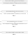
- FIG. 5 illustrates a flow chart according to an exemplary embodiment.
- the second gateway device receives 501 the operational information transmitted by the first gateway device via the wired connection.
- the second gateway device then transmits 502 the operational information to an industrial automation device, for example a variable speed drive, via a second wireless connection, for example a Bluetooth or Wi-Fi connection.
- an industrial automation device for example a variable speed drive
- a second wireless connection for example a Bluetooth or Wi-Fi connection.
- FIG. 6 illustrates a flow chart according to an exemplary embodiment.
- the industrial automation device receives 601 the operational information transmitted by the second gateway device via the second wireless connection.
- a technical advantage provided by some exemplary embodiments may be that using a combination of two wireless connections together with a wired connection may improve the range, data transfer rate, and/or reliability of connectivity between devices that are located far away from each other, for example in comparison to using only one Bluetooth or Wi-Fi connection between the devices, which may not have other means of connectivity with each other.
- the amount of physical cabling needed between the devices may be reduced for example in comparison to using a separate data cable, such as an ethernet cable, between the devices.
- FIG. 7 illustrates an apparatus 700, which may be an apparatus such as, or comprised in, a sensor device according to an exemplary embodiment.
- the apparatus 700 comprises a processor 710.
- the processor 710 interprets computer program instructions and processes data.
- the processor 710 may comprise one or more programmable processors.
- the processor 710 may comprise programmable hardware with embedded firmware and may, alternatively or additionally, comprise one or more application specific integrated circuits, ASICs.
- the processor 710 is coupled to a memory 720.
- the processor is configured to read and write data to and from the memory 720.
- the memory 720 may comprise one or more memory units.
- the memory units may be volatile or non-volatile. It is to be noted that in some exemplary embodiments there may be one or more units of non-volatile memory and one or more units of volatile memory or, alternatively, one or more units of non-volatile memory, or, alternatively, one or more units of volatile memory.
- Volatile memory may be for example RAM, DRAM or SDRAM.
- Non-volatile memory may be for example ROM, PROM, EEPROM, flash memory, optical storage or magnetic storage. In general, memories may be referred to as non-transitory computer readable media.
- the memory 720 stores computer readable instructions that are executed by the processor 710. For example, non-volatile memory stores the computer readable instructions and the processor 710 executes the instructions using volatile memory for temporary storage of data and/or instructions.
- the computer readable instructions may have been pre-stored to the memory 720 or, alternatively or additionally, they may be received, by the apparatus, via electromagnetic carrier signal and/or may be copied from a physical entity such as computer program product. Execution of the computer readable instructions causes the apparatus 700 to perform functionality described above.
- a "memory” or “computer-readable media” may be any non-transitory media or means that can contain, store, communicate, propagate or transport the instructions for use by or in connection with an instruction execution system, apparatus, or device, such as a computer.
- the apparatus 700 further comprises, or is connected to, an input unit 730.
- the input unit 730 comprises one or more interfaces for receiving input.
- the one or more interfaces may comprise for example one or more motion and/or orientation sensors, one or more vibration sensors, one or more temperature sensors, one or more cameras, one or more accelerometers, one or more microphones, one or more buttons and one or more touch detection units.
- the input unit 730 may comprise an interface to which external devices may connect to.
- the apparatus 700 may also comprise an output unit 740.
- the output unit may comprise or be connected to one or more displays capable of rendering visual content such as a light emitting diode, LED, display, a liquid crystal display, LCD or a liquid crystal on silicon, LCoS, display.
- the output unit 740 may further comprise one or more audio outputs.
- the one or more audio outputs may be for example loudspeakers.
- the apparatus 700 may further comprise a connectivity unit 750.
- the connectivity unit 750 enables wireless connectivity to external networks and/or devices.
- the connectivity unit 750 may comprise one or more antennas and one or more receivers that may be integrated to the apparatus 700 or the apparatus 700 may be connected to.
- the connectivity unit 750 may comprise an integrated circuit or a set of integrated circuits that provide the wireless communication capability for the apparatus 700.
- the wireless connectivity may be a hardwired application specific integrated circuit, ASIC.
- the apparatus 700 may further comprise various components not illustrated in FIG. 7 .
- the various components may be hardware components and/or software components.
- the apparatus 800 of FIG. 8 illustrates an exemplary embodiment of an apparatus that may comprise, or be comprised in, a gateway device or an industrial automation device.
- the apparatus may be, for example, a circuitry or a chipset applicable for realizing the described exemplary embodiments.
- the apparatus 800 may be an electronic device comprising one or more electronic circuitries.
- the apparatus 800 may comprise a communication control circuitry 810 such as at least one processor, and at least one memory 820 including a computer program code (software) 822 wherein the at least one memory and the computer program code (software) 822 are configured, with the at least one processor, to cause the apparatus 800 to carry out any one of the exemplary embodiments of the base station described above.
- the memory 820 may be implemented using any suitable data storage technology, such as semiconductor-based memory devices, flash memory, magnetic memory devices and systems, optical memory devices and systems, fixed memory and removable memory.
- the memory may comprise a configuration database for storing configuration data.
- the apparatus 800 may further comprise a communication interface 830 comprising hardware and/or software for realizing communication connectivity according to one or more wired and/or wireless communication protocols.
- the communication interface 830 may provide the apparatus with radio communication capabilities.
- the communication interface may, for example, provide a radio interface to one or more other devices.
- the apparatus 800 may further comprise another interface towards a core network such as a network coordinator apparatus and/or to the access nodes of a cellular communication system.
- the apparatus 800 may further comprise a scheduler 840 that is configured to allocate resources.
- circuitry may refer to one or more or all of the following:
- circuitry also covers an implementation of merely a hardware circuit or processor (or multiple processors) or portion of a hardware circuit or processor and its (or their) accompanying software and/or firmware.
- circuitry also covers, for example and if applicable to the particular claim element, a baseband integrated circuit or processor integrated circuit for a mobile device, a cellular network device, or other computing or network device.
- the techniques and methods described herein may be implemented by various means. For example, these techniques may be implemented in hardware (one or more devices), firmware (one or more devices), software (one or more modules), or combinations thereof.
- the apparatus(es) of exemplary embodiments may be implemented within one or more application-specific integrated circuits (ASICs), digital signal processors (DSPs), digital signal processing devices (DSPDs), programmable logic devices (PLDs), field programmable gate arrays (FPGAs), graphics processing units (GPUs), processors, controllers, micro-controllers, microprocessors, other electronic units designed to perform the functions described herein, or a combination thereof.
- ASICs application-specific integrated circuits
- DSPs digital signal processors
- DSPDs digital signal processing devices
- PLDs programmable logic devices
- FPGAs field programmable gate arrays
- GPUs graphics processing units
- processors controllers, micro-controllers, microprocessors, other electronic units designed to perform the functions described herein, or a
- the implementation can be carried out through modules of at least one chipset (for example procedures, functions, and so on) that perform the functions described herein.
- the software codes may be stored in a memory unit and executed by processors.
- the memory unit may be implemented within the processor or externally to the processor. In the latter case, it can be communicatively coupled to the processor via various means, as is known in the art.
- the components of the systems described herein may be rearranged and/or complemented by additional components in order to facilitate the achievements of the various aspects, etc., described with regard thereto, and they are not limited to the precise configurations set forth in the given drawings, as will be appreciated by one skilled in the art.
Landscapes
- Engineering & Computer Science (AREA)
- Physics & Mathematics (AREA)
- General Physics & Mathematics (AREA)
- Automation & Control Theory (AREA)
- Signal Processing (AREA)
- Computer Networks & Wireless Communication (AREA)
- Human Computer Interaction (AREA)
- Manufacturing & Machinery (AREA)
- Computing Systems (AREA)
- General Health & Medical Sciences (AREA)
- Medical Informatics (AREA)
- Health & Medical Sciences (AREA)
- Arrangements For Transmission Of Measured Signals (AREA)
Abstract
Description
- Various exemplary embodiments relate to a communication system, and particularly to a communication system for industrial automation.
- In an industrial plant, an industrial automation device, for example a variable speed drive, may be located far away from an industrial asset, for example a motor that the industrial automation device is controlling. A data connection between the industrial automation device and the industrial asset may be required in order to transmit sensor measurements from the industrial asset to the industrial automation device. It is desirable to improve the reliability of data connectivity between an industrial automation device and an industrial asset that are located far away from each other in an industrial plant.
- The scope of protection sought for various exemplary embodiments is set out by the independent claims. The exemplary embodiments and features, if any, described in this specification that do not fall under the scope of the independent claims are to be interpreted as examples useful for understanding various exemplary embodiments.
- According to an aspect, there is provided a method comprising measuring, by a sensor device, operational information associated with an industrial asset; transmitting, by the sensor device, the operational information to a first gateway device via a first wireless connection; receiving, by the first gateway device, the operational information via the first wireless connection; transmitting, by the first gateway device, the operational information to a second gateway device via a wired connection; receiving, by the second gateway device, the operational information via the wired connection; transmitting, by the second gateway device, the operational information to an industrial automation device via a second wireless connection; and receiving, by the industrial automation device, the operational information via the second wireless connection.
- According to another aspect, there is provided equipment comprising means for implementing the aforementioned method.
- According to another aspect, there is provided a computer program comprising instructions for causing an apparatus to carry out the aforementioned method.
- According to another aspect, there is provided a computer readable medium comprising program instructions for causing an apparatus to carry out the aforementioned method.
- According to another aspect, there is provided a non-transitory computer readable medium comprising program instructions for causing an apparatus to carry out the aforementioned method.
- According to another aspect, there is provided a system configured to perform the aforementioned method.
- In the following, various exemplary embodiments will be described in greater detail with reference to the accompanying drawings, in which:
-
FIG. 1 illustrates a simplified architecture of a system; -
FIG. 2 illustrates a signalling diagram according to an exemplary embodiment; -
FIGS. 3 to 6 illustrate flow charts according to exemplary embodiments; -
FIGS. 7 and8 illustrate apparatuses according to exemplary embodiments. - The following embodiments are exemplary. Although the specification may refer to "an", "one", or "some" embodiment(s) in several locations of the text, this does not necessarily mean that each such reference is made to the same embodiment(s), or that a particular feature only applies to a single embodiment. Single features of different embodiments may also be combined to provide other embodiments.
- Various exemplary embodiments may be applicable to any process in an industrial plant, including a processing system and/or an industrial manufacturing related process and/or a system for a technical process, which is at least partly automated, providing different measured/sensored values for a plurality of variables on one or more devices (equipment) and/or on one or more processes. A non-limiting list of examples includes power plants, pulp and paper plants, manufacturing plants, chemical processing plants, power transmission systems, mining and mineral processing plants, oil and gas systems, data centers, ships, and transportation fleet systems.
- Different embodiments and examples are described below using single units, models, equipment and memory, without restricting the embodiments/examples to such a solution. Concepts called cloud computing and/or virtualization may be used. Virtualization may allow a single physical computing device to host one or more instances of virtual machines that appear and operate as independent computing devices, so that a single physical computing device can create, maintain, delete, or otherwise manage virtual machines in a dynamic manner. It is also possible that device operations will be distributed among a plurality of servers, nodes, devices or hosts. In cloud computing network devices, computing devices and/or storage devices provide shared resources. Some other technology advancements, such as Software-Defined Networking (SDN) may cause one or more of the functionalities described below to be migrated to any corresponding abstraction or apparatus or device. Therefore, all words and expressions should be interpreted broadly, and they are intended to illustrate, not to restrict, the exemplary embodiments.
- In an industrial plant, an industrial automation device, for example a variable speed drive, may be located far away from an industrial asset, for example a motor that the industrial automation device is controlling. For example, the industrial automation device and the industrial asset may be located over 100 meters or even over 500 meters away from each other. A data connection between the industrial automation device and the industrial asset may be required in order to transmit sensor measurements from the industrial asset to the industrial automation device. However, due to the limited range of wireless communications such as Bluetooth or Wi-Fi, a wireless data connection between the industrial automation device and the industrial asset may not be reliable. Furthermore, a wireless signal may experience attenuation caused by, for example, concrete and/or other structural elements between the industrial automation device and the industrial asset. On the other hand, a separate wired data connection between the industrial automation device and the industrial asset may be impractical, as it may require hundreds of meters or more of additional cabling. In order to address this challenge, some exemplary embodiments provide a data connection between an industrial automation device and a sensor device by using both wireless connectivity and an existing cable, for example a power cable or a PtlOO cable, between the industrial automation device and the industrial asset.
-
FIG. 1 illustrates a system according to an exemplary embodiment. It should be noted thatFIG. 1 illustrates a simplified system architecture only showing some elements and functional entities, all being logical units whose implementation may differ from what is shown. The connections shown inFIG. 1 are logical connections; the actual physical connections may be different. It is apparent to a person skilled in the art that the systems also comprise other functions and structures. It should be appreciated that the functions, structures, elements, and protocols used in or for communication are irrelevant to the exemplary embodiments. Therefore, they need not be discussed in more detail here. - The system comprises one or
more sensor devices 101. Thesensor device 101, for example a smart sensor or an intelligent sensor, may be a condition monitoring sensor that may be attached to, or comprised in, an industrial asset, i.e. machinery. The industrial asset may comprise for example a motor, such as an induction motor, a pump, such as an electric pump, a fan, a compressor, an extruder, and/or a mounted bearing. Thesensor device 101 may be configured to measure operational information, for example observed technical performance information such as measured values for temperature and/or vibration associated with the industrial asset. Thesensor device 101 may measure, for example, operational information associated with the motor, fan, compressor, extruder, or mounted bearing comprised in the industrial asset. Thesensor device 101 may be configured to store the measured operational information for example in an internal memory of thesensor device 101. Thesensor device 101 may be able to connect to the internet for example via a cellular or wireless link, and the sensor device may be further configured to store the operational information for example to a cloud server. Thesensor device 101 may be equipped with a short-range radio interface, for example Bluetooth, Wi-Fi, or a wireless mesh protocol. Thesensor device 101 may be further configured to exchange information, i.e. to transmit and/or receive data, with afirst gateway device 102 via a firstwireless connection 110, for example a Bluetooth or Wi-Fi connection. For example, thesensor device 101 may be configured transmit the measured operational information to thefirst gateway device 102 via the firstwireless connection 110. Thesensor device 101 may be further configured to analyze the operational information, for example to detect and/or predict a fault associated with the industrial asset, and to transmit a warning if a fault is detected or predicted. For example, a fault may be detected if a measured value, such as temperature, associated with the industrial asset exceeds a predetermined threshold value. - The
first gateway device 102 may comprise for example a Bluetooth gateway, an access point, a server computer or a terminal device, such as a smartphone, a desktop computer, a laptop computer or a tablet computer. Thefirst gateway device 102 may be attached to the industrial asset, or located at a close proximity to thesensor device 101, for example less than 10 meters away from thesensor device 101, depending on the range of the wireless technology used by the gateway. For example, thefirst gateway device 102 may be comprised in a junction box or a terminal box of the industrial asset comprising cabling connections for the industrial asset. Thefirst gateway device 102 may be configured to exchange information, i.e. to transmit and/or receive data, with thesensor device 101 via the firstwireless connection 110. For example, thefirst gateway device 102 may be configured to receive the operational information and/or warning(s) from thesensor device 101 via the firstwireless connection 110. Thefirst gateway device 102 may be further configured to store the operational information received from thesensor device 101 for example in an internal memory of thefirst gateway device 102. Thefirst gateway device 102 may be able to connect to the internet for example via a cellular, wireless or wired link, and thefirst gateway device 102 may be further configured to store the operational information for example to a cloud server. Thefirst gateway device 102 may be connected to asecond gateway device 103 via awired connection 111. Thewired connection 111 may comprise for example a power cable or a PtlOO cable. A PtlOO cable is a type of sensor cable that may exist between the industrial automation device and the industrial asset. However, thesensor device 101 may not comprise means for connecting directly to the PtlOO cable or to the power cable. The power cable, for example a three-phase symmetric power cable, may be used to provide power from anindustrial automation device 104 to the industrial asset. Power line communication may be used to transfer information via the power cable. The power cable may also be used to provide power to thefirst gateway device 102 and thesecond gateway device 103. Thefirst gateway device 102 may be configured to exchange information, i.e. to transmit and/or receive data, with thesecond gateway device 103 via thewired connection 111. For example, thefirst gateway device 102 may be configured to transmit the operational information and/or warning(s) to thesecond gateway device 103 via thewired connection 111. - The
second gateway device 103 may be configured to exchange information, i.e. to transmit and/or receive data, with thefirst gateway device 102 via thewired connection 111. For example, thesecond gateway device 103 may be configured to receive the operational information and/or warning(s) from thefirst gateway device 102. Thesecond gateway device 103 may be attached to, or comprised in, theindustrial automation device 104, or located at a close proximity to theindustrial automation device 104, for example less than 10 meters away from theindustrial automation device 104, depending on the range of the wireless technology used by the gateway. Thesecond gateway device 103 may be configured to exchange information, i.e. to transmit and/or receive data, with theindustrial automation device 104, for example a control panel of theindustrial automation device 104, via asecond wireless connection 112, for example a Bluetooth or Wi-Fi connection. For example, thesecond gateway device 103 may be configured to transmit the operational information and/or warning(s) to theindustrial automation device 104 via thesecond wireless connection 112. Thesecond gateway device 103 may comprise for example a Bluetooth gateway, an access point, a server computer or a terminal device, such as a smartphone, a desktop computer, a laptop computer or a tablet computer. - The
industrial automation device 104 may comprise a frequency converter, variable frequency drive, variable speed drive, motion drive, motion controller, motor, servomotor, AC/DC module, DC/AC module, DC/DC module, programmable logic controller (PLC), switch, soft starter, robot, or any other device used for industrial automation. Theindustrial automation device 104, for example a variable speed drive, may be used to run machinery, which may also be referred to as an industrial asset, such as a motor, a pump, a fan or a compressor, at different speeds. Theindustrial automation device 104 may be located for example over 100 meters away from the industrial asset and from thesensor device 101. Theindustrial automation device 104 may comprise or be connected to a controller, for example a proportional-integral-derivative, PID, controller. The controller may be configured to send control signals to theindustrial automation device 104. Theindustrial automation device 104 may control highly dynamic industrial processes, in which for example the speed or the torque applied to a motor has to be varied according to the needs of the industrial process. - The
industrial automation device 104 may store, for example in an internal memory of the industrial automation device, information on control parameter settings, for example present values of parameters such as controller gains, ramp times, motor data, limits, magnetization settings, signal filtering settings, and/or motor control settings. Theindustrial automation device 104 may also store internal technical information recorded during the operation of the industrial automation device, for example information on key performance indicators, such as load current histogram, torque ripple, torque vs. speed curves, and/or power vs. speed curves, temperature, voltage, current, and/or other information such as resonance frequencies and/or load inertias. Theindustrial automation device 104 may be equipped with a short-range radio interface, for example Bluetooth, Wi-Fi or a wireless mesh protocol. Theindustrial automation device 104 may be configured to exchange information, i.e. to transmit and/or receive data, with thesecond gateway device 103 via thesecond wireless connection 112. For example, theindustrial automation device 104 may be configured to receive the operational information and/or warning(s) from thesecond gateway device 103 via thesecond wireless connection 112. Theindustrial automation device 104 may be further configured to adjust or optimize one or more of the control parameter settings of theindustrial automation device 104 based on the received operational information associated with the industrial asset in order to improve the efficiency and/or reliability of the industrial automation device and/or the industrial asset. Theindustrial automation device 104 may be further configured to stop the industrial asset, for example to cut power to the industrial asset, if a warning is received or if the received operational information indicates overheating by the measured temperature value exceeding a pre-defined threshold value, as an example. For example, theindustrial automation device 104 may use model predictive control or a PID controller to adjust the one or more control parameter settings. Theindustrial automation device 104 may further be configured to transmit one or more commands to thesensor device 101 via thesecond gateway device 103 and thefirst gateway device 102. -
FIG. 2 is a signalling diagram illustrating information exchange according to an exemplary embodiment. Referring toFIG. 2 , a sensor device, for example a smart sensor,measures 201 operational information associated with an industrial asset. The industrial asset may comprise for example a motor, such as an induction motor, a pump, such as an electric pump, a fan, a compressor, an extruder, and/or a mounted bearing. The operational information may comprise for example observed technical performance information such as one or more measured values for temperature and/or vibration associated with the industrial asset. The sensor device then transmits 202 the measured operational information to a first gateway device via a first wireless connection. The first gateway device then transmits 203, or forwards, the measured operational information to a second gateway device via a wired connection. The second gateway device then transmits 204, or forwards, the measured operational information to an industrial automation device via a second wireless connection. The industrial automation device may then adjust 205, or optimize, one or more control parameter settings of the industrial automation device based on the received operational information associated with the industrial asset in order to improve the efficiency and/or reliability of the industrial automation device and/or the industrial asset. The industrial automation device may, for example, cut power to the industrial asset, if the received operational information indicates overheating by the measured temperature value exceeding a pre-defined threshold value, as an example. Furthermore, the industrial automation device may transmit 206 one or more commands, or configuration parameter settings, to the sensor device via the second gateway and the first gateway. For example, the industrial automation device may instruct the sensor device to adjust a sampling rate, or time scale, for the measurements performed by the sensor device. The sensor device may then adjust 207 the sampling rate of the measurements based on the one or more commands received from the industrial automation device. For example, the sampling rate may be increased in order to increase the resolution of the measurements, or the sampling rate may be decreased in order to reduce power consumption and thus increase the battery life of the sensor device (if the sensor device comprises a battery). -
FIG. 3 illustrates a flow chart according to an exemplary embodiment. Referring toFIG. 3 , a sensor device, for example a smart sensor,measures 301 operational information associated with an industrial asset, for example a motor, a pump, a mounted bearing, a fan or a compressor. The operational information may comprise for example observed technical performance information such as measured values for temperature and/or vibration associated with the industrial asset. The sensor device then transmits 302 the measured operational information to a first gateway device via a first wireless connection, for example a Bluetooth or Wi-Fi connection. -
FIG. 4 illustrates a flow chart according to an exemplary embodiment. Referring toFIG. 4 , the first gateway device receives 401 the operational information transmitted by the sensor device via the first wireless connection. The first gateway device then transmits 402 the operational information to a second gateway device via a wired connection, for example a power cable or a PtlOO cable. -
FIG. 5 illustrates a flow chart according to an exemplary embodiment. Referring toFIG. 5 , the second gateway device receives 501 the operational information transmitted by the first gateway device via the wired connection. The second gateway device then transmits 502 the operational information to an industrial automation device, for example a variable speed drive, via a second wireless connection, for example a Bluetooth or Wi-Fi connection. -
FIG. 6 illustrates a flow chart according to an exemplary embodiment. Referring toFIG. 6 , the industrial automation device receives 601 the operational information transmitted by the second gateway device via the second wireless connection. - A technical advantage provided by some exemplary embodiments may be that using a combination of two wireless connections together with a wired connection may improve the range, data transfer rate, and/or reliability of connectivity between devices that are located far away from each other, for example in comparison to using only one Bluetooth or Wi-Fi connection between the devices, which may not have other means of connectivity with each other. In addition, the amount of physical cabling needed between the devices may be reduced for example in comparison to using a separate data cable, such as an ethernet cable, between the devices.
-
FIG. 7 illustrates anapparatus 700, which may be an apparatus such as, or comprised in, a sensor device according to an exemplary embodiment. Theapparatus 700 comprises aprocessor 710. Theprocessor 710 interprets computer program instructions and processes data. Theprocessor 710 may comprise one or more programmable processors. Theprocessor 710 may comprise programmable hardware with embedded firmware and may, alternatively or additionally, comprise one or more application specific integrated circuits, ASICs. - The
processor 710 is coupled to amemory 720. The processor is configured to read and write data to and from thememory 720. Thememory 720 may comprise one or more memory units. The memory units may be volatile or non-volatile. It is to be noted that in some exemplary embodiments there may be one or more units of non-volatile memory and one or more units of volatile memory or, alternatively, one or more units of non-volatile memory, or, alternatively, one or more units of volatile memory. Volatile memory may be for example RAM, DRAM or SDRAM. Non-volatile memory may be for example ROM, PROM, EEPROM, flash memory, optical storage or magnetic storage. In general, memories may be referred to as non-transitory computer readable media. Thememory 720 stores computer readable instructions that are executed by theprocessor 710. For example, non-volatile memory stores the computer readable instructions and theprocessor 710 executes the instructions using volatile memory for temporary storage of data and/or instructions. - The computer readable instructions may have been pre-stored to the
memory 720 or, alternatively or additionally, they may be received, by the apparatus, via electromagnetic carrier signal and/or may be copied from a physical entity such as computer program product. Execution of the computer readable instructions causes theapparatus 700 to perform functionality described above. - In the context of this document, a "memory" or "computer-readable media" may be any non-transitory media or means that can contain, store, communicate, propagate or transport the instructions for use by or in connection with an instruction execution system, apparatus, or device, such as a computer.
- The
apparatus 700 further comprises, or is connected to, aninput unit 730. Theinput unit 730 comprises one or more interfaces for receiving input. The one or more interfaces may comprise for example one or more motion and/or orientation sensors, one or more vibration sensors, one or more temperature sensors, one or more cameras, one or more accelerometers, one or more microphones, one or more buttons and one or more touch detection units. Further, theinput unit 730 may comprise an interface to which external devices may connect to. - The
apparatus 700 may also comprise anoutput unit 740. The output unit may comprise or be connected to one or more displays capable of rendering visual content such as a light emitting diode, LED, display, a liquid crystal display, LCD or a liquid crystal on silicon, LCoS, display. Theoutput unit 740 may further comprise one or more audio outputs. The one or more audio outputs may be for example loudspeakers. - The
apparatus 700 may further comprise aconnectivity unit 750. Theconnectivity unit 750 enables wireless connectivity to external networks and/or devices. Theconnectivity unit 750 may comprise one or more antennas and one or more receivers that may be integrated to theapparatus 700 or theapparatus 700 may be connected to. Theconnectivity unit 750 may comprise an integrated circuit or a set of integrated circuits that provide the wireless communication capability for theapparatus 700. Alternatively, the wireless connectivity may be a hardwired application specific integrated circuit, ASIC. - It is to be noted that the
apparatus 700 may further comprise various components not illustrated inFIG. 7 . The various components may be hardware components and/or software components. - The
apparatus 800 ofFIG. 8 illustrates an exemplary embodiment of an apparatus that may comprise, or be comprised in, a gateway device or an industrial automation device. The apparatus may be, for example, a circuitry or a chipset applicable for realizing the described exemplary embodiments. Theapparatus 800 may be an electronic device comprising one or more electronic circuitries. Theapparatus 800 may comprise acommunication control circuitry 810 such as at least one processor, and at least onememory 820 including a computer program code (software) 822 wherein the at least one memory and the computer program code (software) 822 are configured, with the at least one processor, to cause theapparatus 800 to carry out any one of the exemplary embodiments of the base station described above. - The
memory 820 may be implemented using any suitable data storage technology, such as semiconductor-based memory devices, flash memory, magnetic memory devices and systems, optical memory devices and systems, fixed memory and removable memory. The memory may comprise a configuration database for storing configuration data. - The
apparatus 800 may further comprise acommunication interface 830 comprising hardware and/or software for realizing communication connectivity according to one or more wired and/or wireless communication protocols. Thecommunication interface 830 may provide the apparatus with radio communication capabilities. The communication interface may, for example, provide a radio interface to one or more other devices. Theapparatus 800 may further comprise another interface towards a core network such as a network coordinator apparatus and/or to the access nodes of a cellular communication system. Theapparatus 800 may further comprise ascheduler 840 that is configured to allocate resources. - As used in this application, the term "circuitry" may refer to one or more or all of the following:
- a. hardware-only circuit implementations (such as implementations in only analog and/or digital circuitry) and
- b. combinations of hardware circuits and software, such as (as applicable):
- i. a combination of analog and/or digital hardware circuit(s) with software/firmware and
- ii. any portions of hardware processor(s) with software (including digital signal processor(s)), software, and memory(ies) that work together to cause an apparatus, such as a mobile phone, to perform various functions) and
- c. hardware circuit(s) and or processor(s), such as a microprocessor(s) or a portion of a microprocessor(s), that requires software (for example firmware) for operation, but the software may not be present when it is not needed for operation.
- This definition of circuitry applies to all uses of this term in this application, including in any claims. As a further example, as used in this application, the term circuitry also covers an implementation of merely a hardware circuit or processor (or multiple processors) or portion of a hardware circuit or processor and its (or their) accompanying software and/or firmware. The term circuitry also covers, for example and if applicable to the particular claim element, a baseband integrated circuit or processor integrated circuit for a mobile device, a cellular network device, or other computing or network device.
- The techniques and methods described herein may be implemented by various means. For example, these techniques may be implemented in hardware (one or more devices), firmware (one or more devices), software (one or more modules), or combinations thereof. For a hardware implementation, the apparatus(es) of exemplary embodiments may be implemented within one or more application-specific integrated circuits (ASICs), digital signal processors (DSPs), digital signal processing devices (DSPDs), programmable logic devices (PLDs), field programmable gate arrays (FPGAs), graphics processing units (GPUs), processors, controllers, micro-controllers, microprocessors, other electronic units designed to perform the functions described herein, or a combination thereof. For firmware or software, the implementation can be carried out through modules of at least one chipset (for example procedures, functions, and so on) that perform the functions described herein. The software codes may be stored in a memory unit and executed by processors. The memory unit may be implemented within the processor or externally to the processor. In the latter case, it can be communicatively coupled to the processor via various means, as is known in the art. Additionally, the components of the systems described herein may be rearranged and/or complemented by additional components in order to facilitate the achievements of the various aspects, etc., described with regard thereto, and they are not limited to the precise configurations set forth in the given drawings, as will be appreciated by one skilled in the art.
- It will be obvious to a person skilled in the art that, as technology advances, the inventive concept may be implemented in various ways. The embodiments are not limited to the exemplary embodiments described above, but may vary within the scope of the claims. Therefore, all words and expressions should be interpreted broadly, and they are intended to illustrate, not to restrict, the exemplary embodiments.
Claims (15)
- A method comprising:measuring, by a sensor device, operational information associated with an industrial asset;transmitting, by the sensor device, the operational information to a first gateway device via a first wireless connection;receiving, by the first gateway device, the operational information via the first wireless connection;transmitting, by the first gateway device, the operational information to a second gateway device via a wired connection;receiving, by the second gateway device, the operational information via the wired connection;transmitting, by the second gateway device, the operational information to an industrial automation device via a second wireless connection;receiving, by the industrial automation device, the operational information via the second wireless connection.
- A method according to claim 1, further comprising:
adjusting, by the industrial automation device, one or more control parameter settings based on the received operational information. - A method according to any preceding claim, further comprising transmitting, by the industrial automation device, one or more commands to the sensor device via the first gateway device and the second gateway device;
wherein the one or more commands are used to adjust a sampling rate for measuring the operational information associated with the industrial asset by the sensor device. - A method according to any preceding claim, wherein the wired connection comprises a power cable or a PtlOO cable, wherein the power cable is used to provide power from the industrial automation device to the industrial asset.
- A method according to claim 4, wherein the power cable is further used to provide power from the industrial automation device to the first gateway device and to the second gateway device.
- Equipment comprising means for implementing a method as claimed in any preceding claim.
- A computer program comprising instructions for causing an apparatus to carry out a method as claimed in any of claims 1-5.
- A system comprising:at least one sensor device (101), a first gateway device (102), a second gateway device (103), and an industrial automation device (104);wherein the sensor device (101) is configured to:measure operational information associated with an industrial asset;transmit the operational information to the first gateway device (102) via a first wireless connection (110);wherein the first gateway device (102) is configured to:receive the operational information from the sensor device (101) via the first wireless connection (110);transmit the operational information to the second gateway device (103) via a wired connection (111);wherein the second gateway device (103) is configured to:receive the operational information from the first gateway device (102) via the wired connection (111);transmit the operational information to the industrial automation device (104) via a second wireless connection (112);wherein the industrial automation device (104) is configured to:receive the operational information from the second gateway device (103) via the second wireless connection (112).
- A system according to claim 8, wherein the industrial automation device (104) is further configured to adjust one or more control parameter settings based on the received operational information.
- A system according to any of claims 8-9, wherein the industrial automation device (104) is further configured to transmit one or more commands to the sensor device (101) via the first gateway device (102) and the second gateway device (103); and
wherein the sensor device (101) is further configured to receive the one or more commands and adjust, based on the received one or more commands, a sampling rate for measuring the operational information associated with the industrial asset. - A system according to any of claims 8-10, wherein the wired connection (111) comprises a power cable or a PtlOO cable, wherein the power cable is used to provide power from the industrial automation device (104) to the industrial asset.
- A system according to claim 11, wherein the power cable is further used to provide power from the industrial automation device (104) to the first gateway device (102) and to the second gateway device (103).
- A system according to any of claims 8-12, wherein the operational information comprises measured values at least for temperature and/or vibration associated with the industrial asset.
- A system according to any of claims 8-13, wherein the industrial asset comprises a motor, a pump, a compressor, a fan, an extruder, and/or a mounted bearing.
- A system according to any of claims 8-14, wherein the industrial automation device (104) comprises a variable speed drive.
Priority Applications (2)
| Application Number | Priority Date | Filing Date | Title |
|---|---|---|---|
| EP20183107.0A EP3933518A1 (en) | 2020-06-30 | 2020-06-30 | A communication system and method for industrial automation |
| US17/356,645 US20210405618A1 (en) | 2020-06-30 | 2021-06-24 | Communication System And Method For Industrial Automation |
Applications Claiming Priority (1)
| Application Number | Priority Date | Filing Date | Title |
|---|---|---|---|
| EP20183107.0A EP3933518A1 (en) | 2020-06-30 | 2020-06-30 | A communication system and method for industrial automation |
Publications (1)
| Publication Number | Publication Date |
|---|---|
| EP3933518A1 true EP3933518A1 (en) | 2022-01-05 |
Family
ID=71409156
Family Applications (1)
| Application Number | Title | Priority Date | Filing Date |
|---|---|---|---|
| EP20183107.0A Withdrawn EP3933518A1 (en) | 2020-06-30 | 2020-06-30 | A communication system and method for industrial automation |
Country Status (2)
| Country | Link |
|---|---|
| US (1) | US20210405618A1 (en) |
| EP (1) | EP3933518A1 (en) |
Families Citing this family (1)
| Publication number | Priority date | Publication date | Assignee | Title |
|---|---|---|---|---|
| US12047196B2 (en) * | 2021-12-08 | 2024-07-23 | Hamilton Sundstrand Corporation | Control system architecture for atmospheric suit |
Citations (3)
| Publication number | Priority date | Publication date | Assignee | Title |
|---|---|---|---|---|
| CN102014524A (en) * | 2010-11-24 | 2011-04-13 | 北京福星晓程电子科技股份有限公司 | Wireless sensor network and power line communication-based chip and monitoring system |
| US20180216990A1 (en) * | 2017-01-31 | 2018-08-02 | ProAxion, Inc. | Devices, methods and computer program products providing multi-axis vibrational measurement with predictive analysis |
| US20180343147A1 (en) * | 2017-05-24 | 2018-11-29 | Yokogawa Electric Corporation | Wireless gateway system and communication method thereof |
Family Cites Families (10)
| Publication number | Priority date | Publication date | Assignee | Title |
|---|---|---|---|---|
| US7889747B2 (en) * | 2006-05-31 | 2011-02-15 | Honeywell International Inc. | Apparatus, system, and method for integrating a wireless network with wired field devices in a process control system |
| JP5500185B2 (en) * | 2012-01-24 | 2014-05-21 | 横河電機株式会社 | Wireless gateway device |
| JP5598505B2 (en) * | 2012-07-23 | 2014-10-01 | 横河電機株式会社 | Gateway device, communication system, and communication method |
| US9191843B2 (en) * | 2013-06-12 | 2015-11-17 | Honeywell International Inc. | Apparatus and method for measuring and reporting redundant wireless connectivity over time |
| US20170108854A1 (en) * | 2015-10-19 | 2017-04-20 | Honeywell International Inc. | Scanner with overrun alert for process control |
| US10165531B1 (en) * | 2015-12-17 | 2018-12-25 | Spearlx Technologies, Inc. | Transmission and reception of signals in a time synchronized wireless sensor actuator network |
| US10503668B2 (en) * | 2016-10-18 | 2019-12-10 | Honeywell International Inc. | Intelligent field input/output (I/O) terminal for industrial control and related system and method |
| EP3615652A4 (en) * | 2017-04-28 | 2021-03-03 | Limestone Coast Brewing Company Pty Ltd | Brewing arrangement and method |
| US11086298B2 (en) * | 2019-04-15 | 2021-08-10 | Rockwell Automation Technologies, Inc. | Smart gateway platform for industrial internet of things |
| CN209692794U (en) * | 2019-05-10 | 2019-11-26 | 深圳市讯鹏科技有限公司 | A kind of industrial intelligent gateway of internet of things |
-
2020
- 2020-06-30 EP EP20183107.0A patent/EP3933518A1/en not_active Withdrawn
-
2021
- 2021-06-24 US US17/356,645 patent/US20210405618A1/en not_active Abandoned
Patent Citations (3)
| Publication number | Priority date | Publication date | Assignee | Title |
|---|---|---|---|---|
| CN102014524A (en) * | 2010-11-24 | 2011-04-13 | 北京福星晓程电子科技股份有限公司 | Wireless sensor network and power line communication-based chip and monitoring system |
| US20180216990A1 (en) * | 2017-01-31 | 2018-08-02 | ProAxion, Inc. | Devices, methods and computer program products providing multi-axis vibrational measurement with predictive analysis |
| US20180343147A1 (en) * | 2017-05-24 | 2018-11-29 | Yokogawa Electric Corporation | Wireless gateway system and communication method thereof |
Also Published As
| Publication number | Publication date |
|---|---|
| US20210405618A1 (en) | 2021-12-30 |
Similar Documents
| Publication | Publication Date | Title |
|---|---|---|
| AU2021293027B2 (en) | Edge controller for a facility | |
| US10375208B2 (en) | Optimisation of industrial device parameters in a communications system | |
| US20150372865A1 (en) | System and method for autonomous dynamic provisioning | |
| EP4095627A1 (en) | Evaluating alternative control parameters based on a digital twin | |
| US20210405618A1 (en) | Communication System And Method For Industrial Automation | |
| US20170168473A1 (en) | Signalling of specification information on an industrial device | |
| US12045041B2 (en) | Wireless communication for industrial automation | |
| US20230152768A1 (en) | Extrapolating motor energy consumption based on digital twin | |
| US11520316B2 (en) | Determining control parameters for an industrial automation device | |
| CN112995957B (en) | Control method and device of Internet of things terminal, internet of things terminal and system | |
| US20240103499A1 (en) | Method for controlling and/or operating an automation component | |
| KR101265535B1 (en) | Monitoring apparatus and method thereof | |
| Vinay | Monitoring and controlling of smart equipments in manufacturing industry using IoT applications | |
| EP3346384B1 (en) | Industrial device fault management in a communications system | |
| EP3220608B1 (en) | Retrieval of industrial device data in a communications system | |
| CN204287900U (en) | A kind of tyre building machine long distance control system | |
| CN113098979B (en) | Ranging monitoring system and method | |
| EP4047881A1 (en) | Determining diagnostics information based on non-real-time data | |
| US20220204315A1 (en) | System and method for addressing elevator drive faults | |
| CN110324398B (en) | Method for remotely supporting an electric drive device | |
| CN104570843B (en) | A kind of modular i/O axle controls control method, system and burning IC equipment | |
| CN118655853A (en) | Device control method, apparatus, device, storage medium, and program product | |
| KR20220076233A (en) | CONNECTIVITY MANAGEMENT APPARATUS AND METHOD FOR INTERFERENCE RELAXATION BETWEEN HETEROGENEOUS WIRELESS DEVICES OF EDGE GATEWAY UNDER IoT SENSOR ENVIRONMENT | |
| KR20220076234A (en) | SMART FACTORY MANAGEMET SYSTEM USING IoT GATEWAY BASED ON EDGE COMPUTING | |
| CN116257025A (en) | Industrial data acquisition system and method |
Legal Events
| Date | Code | Title | Description |
|---|---|---|---|
| PUAI | Public reference made under article 153(3) epc to a published international application that has entered the european phase |
Free format text: ORIGINAL CODE: 0009012 |
|
| STAA | Information on the status of an ep patent application or granted ep patent |
Free format text: STATUS: THE APPLICATION HAS BEEN PUBLISHED |
|
| AK | Designated contracting states |
Kind code of ref document: A1 Designated state(s): AL AT BE BG CH CY CZ DE DK EE ES FI FR GB GR HR HU IE IS IT LI LT LU LV MC MK MT NL NO PL PT RO RS SE SI SK SM TR |
|
| B565 | Issuance of search results under rule 164(2) epc |
Effective date: 20201201 |
|
| STAA | Information on the status of an ep patent application or granted ep patent |
Free format text: STATUS: REQUEST FOR EXAMINATION WAS MADE |
|
| 17P | Request for examination filed |
Effective date: 20220630 |
|
| RBV | Designated contracting states (corrected) |
Designated state(s): AL AT BE BG CH CY CZ DE DK EE ES FI FR GB GR HR HU IE IS IT LI LT LU LV MC MK MT NL NO PL PT RO RS SE SI SK SM TR |
|
| STAA | Information on the status of an ep patent application or granted ep patent |
Free format text: STATUS: EXAMINATION IS IN PROGRESS |
|
| 17Q | First examination report despatched |
Effective date: 20231002 |
|
| STAA | Information on the status of an ep patent application or granted ep patent |
Free format text: STATUS: THE APPLICATION IS DEEMED TO BE WITHDRAWN |
|
| 18D | Application deemed to be withdrawn |
Effective date: 20240213 |