EP3346384B1 - Industrial device fault management in a communications system - Google Patents
Industrial device fault management in a communications system Download PDFInfo
- Publication number
- EP3346384B1 EP3346384B1 EP17150819.5A EP17150819A EP3346384B1 EP 3346384 B1 EP3346384 B1 EP 3346384B1 EP 17150819 A EP17150819 A EP 17150819A EP 3346384 B1 EP3346384 B1 EP 3346384B1
- Authority
- EP
- European Patent Office
- Prior art keywords
- fault
- user
- drive
- information
- computing apparatus
- Prior art date
- Legal status (The legal status is an assumption and is not a legal conclusion. Google has not performed a legal analysis and makes no representation as to the accuracy of the status listed.)
- Active
Links
Images


Classifications
-
- G—PHYSICS
- G06—COMPUTING; CALCULATING OR COUNTING
- G06F—ELECTRIC DIGITAL DATA PROCESSING
- G06F11/00—Error detection; Error correction; Monitoring
- G06F11/07—Responding to the occurrence of a fault, e.g. fault tolerance
- G06F11/0703—Error or fault processing not based on redundancy, i.e. by taking additional measures to deal with the error or fault not making use of redundancy in operation, in hardware, or in data representation
- G06F11/0793—Remedial or corrective actions
-
- G—PHYSICS
- G06—COMPUTING; CALCULATING OR COUNTING
- G06F—ELECTRIC DIGITAL DATA PROCESSING
- G06F11/00—Error detection; Error correction; Monitoring
- G06F11/07—Responding to the occurrence of a fault, e.g. fault tolerance
- G06F11/0703—Error or fault processing not based on redundancy, i.e. by taking additional measures to deal with the error or fault not making use of redundancy in operation, in hardware, or in data representation
- G06F11/0706—Error or fault processing not based on redundancy, i.e. by taking additional measures to deal with the error or fault not making use of redundancy in operation, in hardware, or in data representation the processing taking place on a specific hardware platform or in a specific software environment
- G06F11/0748—Error or fault processing not based on redundancy, i.e. by taking additional measures to deal with the error or fault not making use of redundancy in operation, in hardware, or in data representation the processing taking place on a specific hardware platform or in a specific software environment in a remote unit communicating with a single-box computer node experiencing an error/fault
-
- G—PHYSICS
- G06—COMPUTING; CALCULATING OR COUNTING
- G06F—ELECTRIC DIGITAL DATA PROCESSING
- G06F11/00—Error detection; Error correction; Monitoring
- G06F11/22—Detection or location of defective computer hardware by testing during standby operation or during idle time, e.g. start-up testing
- G06F11/2294—Detection or location of defective computer hardware by testing during standby operation or during idle time, e.g. start-up testing by remote test
-
- G—PHYSICS
- G06—COMPUTING; CALCULATING OR COUNTING
- G06F—ELECTRIC DIGITAL DATA PROCESSING
- G06F11/00—Error detection; Error correction; Monitoring
- G06F11/30—Monitoring
- G06F11/3058—Monitoring arrangements for monitoring environmental properties or parameters of the computing system or of the computing system component, e.g. monitoring of power, currents, temperature, humidity, position, vibrations
Definitions
- the invention relates to a communications system, and particularly to performing fault management regarding an industrial automation device.
- Frequency converters are used to change frequency and magnitude of electricity supplied to a load. Frequency converters are being used, for example, in alternating current (AC) motor drives.
- a frequency converter receives AC current from an electrical power supply and converts the frequency of the received AC current to another frequency after which the AC current is supplied to an AC electric motor. Also further parameters, for example, a voltage level of the received AC current may be changed.
- the AC motors are used in various applications including, for example, fans and pumps. In many applications the use of frequency converters may provide significant energy savings compared to supplying electrical power having a constant frequency.
- Document US-A1-2016/0077910 discloses a system and a method for providing software supportability involve a server receiving a first electronic record from a client application on a mobile computing device.
- the first electronic record describes activity that occurred at the mobile computing device during a request sent from the client application to the server.
- the server creates a second electronic record that describes activity that occurred at the server while processing the request.
- the first electronic record and the second electronic record are stored in association with each other and can be analysed to determine issues with performance or security.
- a diagnostic application based on the stored first electronic record and the second electronic record, identifies at least one faulty component at the server or the mobile computing device to correct the identified at least one faulty component.
- Document EP-A1-3 101 777 discloses a method which comprises receiving, in a local terminal device of a communication system, a set of instructions related to a frequency converter, the set of instructions having been transmitted from a remote terminal device via at least one network node.
- the local terminal device displays information on the received set of instructions.
- the local terminal device may detect a predetermined user input, and in response to the detecting, the local terminal device causes transmission of control data to the frequency converter via a communications link established between the local terminal device and the frequency converter, if the user input indicates that the user of the local terminal device approves the execution of the set of instructions in the frequency converter, the control data commanding the frequency converter to execute the set of instructions in the frequency converter.
- Some embodiments provide a method, system, apparatus and a computer program product for fault management of an automated power conversion device.
- Figure 1 illustrates a wireless communication scenario to which embodiments of the invention may be applied.
- an example of a radio system to which embodiments of the invention may be applied is based on LTE network elements.
- an embodiment is not limited to the LTE radio communications systems but may also be implemented in other radio communications systems, such as 3G, 4G, 5G, LTE-A, UMTS (universal mobile telecommunications system), EDGE, WCDMA, Bluetooth network, WLAN or any other mobile or wireless network.
- the presented solution may be applied between user equipment belonging to different but compatible systems such as LTE and UMTS.
- Figure 1 illustrates a simplified system architecture only showing some elements and functional entities, all being logical units whose implementation may differ from what is shown.
- the connections shown in Figure 1 are logical connections; the actual physical connections may be different. It is apparent to a person skilled in the art that the systems also comprise other functions and structures. It should be appreciated that the functions, structures, elements, and protocols used in or for wireless communication are irrelevant to the actual invention. Therefore, they need not be discussed in more detail here.
- Figure 1 illustrates a communication system according to an embodiment.
- Figure 1 illustrates an exemplary communications system in which a computing apparatus such as a user terminal 105 is able to connect to a network node (network element NE) such as a cloud server 109 and to an automated power conversion device such as a drive 101.
- the user terminal 105 may be a local terminal device (local device) UE1 located on-site at a close proximity of the drive 101.
- the local terminal device 105 may comprise a user equipment UE1 such as a smartphone, mobile phone, tablet computer or laptop computer.
- a connection 106 of the local terminal device 105 to the network node 109 may be provided by a cellular, wireless or wired link.
- a connection 104 of the local terminal device 105 to the drive 101 may be provided e.g. by a Bluetooth, WLAN, NFC (near field communication), or inductive connection (such as an inductive connection according to an inductive power standard (Qi) by the Wireless Power Consortium). It is also possible that the connection 104 of the local terminal device 105 to the drive 101 is a wired connection implemented e.g. by means of a universal serial bus (USB).
- USB universal serial bus
- the network node 109 may be a remote computing apparatus comprising or being connected to a remote terminal device UE2 112, server NE 109 or database DB 111 located at a service center, for facilitating service and maintenance of the drive 101.
- the remote apparatus(es) may facilitate different ways of how to communicate with the drive 101 via the local terminal device 105.
- the remote device 109, 111, 112 may comprise e.g. a server, database, desktop computer, laptop computer, tablet computer, smartphone, mobile phone, etc. Any suitable technology that makes it possible to store drive data, drive fault data and drive fault debugging data into a service center database 111 may be utilized.
- a cloud service may be used via the internet to store drive data, fault data and drive fault debugging data into the service center database 111.
- the local and remote apparatuses may be capable of communicating with each other via the connection 106, 110, 113, 114 by utilizing the cloud service e.g. via the internet.
- the remote terminal device UE2 112, server NE 109 and/or database DB 111 are located on-site near the device 101.
- the actual physical location of the cloud service/cloud server is not relevant to the embodiment, but instead the remote terminal device UE2 112, server NE 109 and/or database DB 111 may be located in any convenient location.
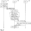
- FIG. 2 is a signalling diagram illustrating a computerized method for drive fault management in network node a communications system.
- the network node 105, 109, 111, 112 may be a terminal device, user equipment, host computer, server computer, base station, access node or any other network element.
- the server computer or the host computer may generate a virtual network through which the host computer communicates with the terminal device.
- the drive 101 is configured to store (block 201) data related to various internal variables and key performance indicators (KPI) about the condition/status of the frequency converter or the drive system (e.g. power-on time, motor running hours, fan running hours, estimation of the DC (direct current) link capacitor lifetime, load current histogram, temperature (ambient temperature, insulated gate bipolar transistor (IGBT) temperature, control board temperature, etc.), frequency, DC link voltage, current(s), status words, internal control references, etc.).
- KPI key performance indicators
- This data in combination with drive identification data may be referred to as drive status data (which may be stored e.g. in an internal memory of the drive).
- the drive may detect (block 202) an operational fault in the drive and/or in the device (such as a fan, pump) the drive is controlling.
- the fault or error may also occur in (and/or be detected by) a drive option module such as a fieldbus adapter.
- the adapter may include its own fault logging system from which the fault data may be transferred to the drive and added to data blocks.
- the fault data may also originate from a control system such as PLC, and/or the fault data may be collected by the control system.
- the drive is configured to record information on the fault (also referred to as fault log data herein) such as a fault code and possibly other device-recordable data.
- the drive status data and the fault log data are transmitted (block 203) to the user apparatus 105 via a local communications connection 104 (such as Bluetooth, mobile, wireless, wired, NFC, inductive connection).
- the drive status data and/or fault log data may be transmitted 203 to the user apparatus 105 automatically when the fault is detected in the drive 101.
- the fault log data and/or the drive status data may be transmitted 203 from the drive 101 to the user apparatus 105 in response to the user apparatus 105 requesting it.
- the drive status data and the fault log data are received in the user apparatus 105. Based on at least the received fault log data and device status data, the user apparatus 105 is configured to execute (block 205) one or more fault tracing steps related to the drive 101, in order to try to solve the fault situation.
- the executing 205 of at least one of the fault tracing steps may comprise, for example, outputting a drive related inquiry to a user and receiving a user response to the drive related inquiry, causing the running of one or more operational tests on the drive 101, requesting and receiving further drive related information from the drive 101 via the local connection network 104, requesting and receiving further drive related information from the remote apparatus 109 via the communications network 106, generating and outputting a drive related checklist to the user in respect of the fault, generating and outputting a drive related question to the user in respect of the fault, and/or generating and outputting a suggestion for a corrective action to the user in respect of the fault (instead of or in addition to the drive, these steps may relate to the device the drive is controlling).
- the user apparatus 105 may output (block 206) a request (via an appropriate user interface in the user apparatus) to the user, requesting the user to indicate to the user apparatus 105 whether or not the fault was corrected. If the user indicates (block 206, via an appropriate user interface (e.g. keyboard, touch display, microphone) in the user apparatus 105) to the user apparatus 105 that the drive fault was not corrected, the user apparatus 105 may execute 205 at least one other or updated fault tracing steps related to the drive to try to solve the fault situation.
- an appropriate user interface e.g. keyboard, touch display, microphone
- the user apparatus 105 may cause (block 207) transmission of the fault log data, the device status data, information on the executed fault tracing step(s), and other debugging data (such as user-entered debugging data) related to the drive to a remote apparatus 109 (such as a cloud server), for further analysis of the fault.
- a remote apparatus 109 such as a cloud server
- the user apparatus may cause (block 207) transmission of the fault log data, the device status data, the information on the executed fault tracing step(s), and the other debugging data to the remote apparatus 109 to be stored 208 in a memory/database 111. At least part of that information may also be stored 206 in an internal memory/database of the user apparatus.
- the computing apparatus 105 may interact with at least one of the user, the drive 101 and the remote apparatus 109, 111 to obtain more information on at least the fault and/or the drive 101, and utilize the obtained information when generating/selecting/executing the fault tracing steps.
- the fault tracing step executed in the computing apparatus 105 may be selected based on information obtained from one or more earlier device fault tracing steps. This enables providing a self-learning system where the fault tracing steps may be dynamically customized for the drive 101 and the operational fault of the drive 101. This enables performing efficient drive self-diagnosis and drive self-diagnosis information sharing in the communications system.
- the method may comprise causing storing, in a memory (e.g. database 111), associated information on one or more of the suggestion for the corrective action, whether or not the fault was corrected, the fault tracing step, the fault log data, the device status data, the further device related information, the device related inquiry and the user response, the operational test, a result of the operational test, the device related checklist, the device related question, user-entered information, other debugging data; the further fault analysis, and a result of the further fault analysis.
- the computing apparatus 105 may utilize the stored information later as source information when generating and executing a subsequent fault tracing step related to the same or different drive 101 (and possibly same fault or same type of fault).
- the computing apparatus 105 may also output a request to the user, and may detect a user input indicating whether or not the updated fault tracing step enables the drive fault to be corrected.
- the computing apparatus 105 causes 207 transmission of the drive data, fault data, and information on the executed fault tracing step(s) and other debugging data to the remote apparatus 109. These may then be stored 208 in the remote apparatus 109 and/or database 111.
- a further drive fault analysis may be performed in the remote apparatus 109 based on information received from the user apparatus 105 and based on earlier fault, drive, fault tracing and/or debugging related information stored in the remote apparatus 109 and/or database 111.
- the remote apparatus 109 may cause transmission of information on the result of the further fault analysis to the user apparatus 105.
- the user apparatus 105 may receive the information on the result of the further fault analysis, and output said information to the user. This output information may further help the user to try to solve the issue with the drive 101.
- one or more further fault tracing steps 205 may also be performed in the user apparatus 105 if needed/desired.
- the message 207 may comprise a request for performing a further fault analysis. If needed, the further fault analysis may also be conducted by the user of the remote user apparatus 112, based on information received 208 from the user apparatus 105 and based on earlier fault, drive, fault tracing and/or debugging related information stored in the remote apparatus 109 and/or database 111. In that case the remote user apparatus 112 may cause transmission of information on the result of the further fault analysis directly to the local user apparatus 105 via the connection 114 or otherwise.
- the drive 101 is configured to record selected key parameters and status information, e.g. hours operated and temperature cycles, related to the drive 101. If needed (e.g. a fault appeared in the drive 101), it is possible to establish a communications connection 104 between the drive 101 and a local computing apparatus 105.
- the local computing apparatus 105 may be a user terminal 105, such as a mobile phone 105, smart phone 105, laptop computer 105, or tablet 105.
- the data that is stored in the drive 101 may be downloaded/transmitted from the drive 101 to the computing apparatus 105.
- the computing apparatus 105 By analysing the downloaded data in the computing apparatus 105, the computing apparatus 105 is able to automatically generate a series of debugging/troubleshooting procedures (also referred to as a fault tracing steps) based on the current condition of the drive 101.
- the generated fault tracing steps enable the computing apparatus 105 to interact with the user, the drive 101, a cloud computing apparatus 109 and/or a database 111, to check, test and/or adjust various issues in relation to the drive 101.
- These steps may include the computing apparatus 105 outputting a series of questions and receiving a user response to them (e.g.
- the computing apparatus 105 outputting simple recommendations on tests to be initialized by the user (such as recommendations on changing parameters), and trials to find out if the recommendations work.
- Relevant data drive parameters, performance, user responses to the questions, environment variables, e.g. location and weather
- the data above may be transmitted from the computing apparatus 105 to the (possibly remotely located) cloud computing apparatus 109 (such as a database server, service server or cloud server 109) which a drive support team has access to, for further analysis.
- the data from the drive 101 and the recorded self-debugging data may be made accessible to the drive support team via the cloud server 109.
- a support engineer remote or on-site
- the cloud server 109 thereby a support engineer (remote or on-site) is able to understand the condition of the drive 101 immediately by connecting (by means of UE2 112) to the cloud server 109, and the user does not need to repeat the situation.
- the whole service process may be made much more effective both for the local user and the drive support team.
- the computing apparatus 105 may try to solve an issue that the user is having with the drive 101, by utilizing a drive-specific and fault-specific debugging wizard script comprising one or more fault tracing steps.
- the computing apparatus 105 requests data from the drive 101 and from the database 111 (e.g. a diagnosis database).
- the data received in the computing apparatus 105 from the drive 101 comprises e.g. key parameter values and fault logger data which are requested or automatically transmitted from the drive 101 to the computing apparatus 105 using a wireless connection 104 between the drive 101 and the computing apparatus 105.
- the diagnosis database may be a sub-set of a comprehensive database 111 located in or connected to the cloud server 109.
- installation information on the drive 101 may be requested from the database 111 (e.g.
- the computing apparatus 105 tries to solve the issue by outputting queries to the user, by performing tests, and/or by outputting solution proposals. This series of steps is intelligently selected in the computing apparatus 105 based on information obtained from previous steps. Between the steps, the computing apparatus 105 may request more data from the cloud server 109 or from the drive 101, if needed. Moreover, the computing apparatus 105 may be configured to cause the drive 101 to perform the tests. The computing apparatus 105 records the steps and the data obtained when performing the steps, and transmits the recorded data to the database 111. The data obtained/transmitted may be later used for solving a subsequent issue with a drive.
- the process starts in the same way as described above. However, after a few steps the user and/or the computing apparatus 105 may conclude 205 that the issue with the drive 101 is not solvable by means of the debugging wizard script. At that point, the computing device may output 206 (e.g. on a display) information indicating to the user, for example, that assistance from a support engineer is required (e.g. when the algorithm is not (anymore) confident about the possible cause of the situation or when it knows that this situation requires help from a support line), and/or the user may decide that the problem was not fixed.
- assistance from a support engineer e.g. when the algorithm is not (anymore) confident about the possible cause of the situation or when it knows that this situation requires help from a support line
- the computing apparatus 105 may comprise a user interface by means of which the user may insert 206 additional information on the drive fault in a form of text, pictures and/or videos to further elaborate the issue.
- the computing apparatus 105 is configured to cause transmission 207 of the user-inserted information, the drive data, the additional information, and/or information on the recorded solving procedure to the cloud server 109.
- the support engineer may then try to solve the drive fault issue based on the information received 208 in the cloud server 109 and/or contact the user of UE1 (the support engineer may be the user of the remote computing apparatus UE2 112).
- a user receives 204 an overcurrent fault notification (including a specific fault code) in his computing apparatus 105 from a drive 101 used control a conveyor belt.
- the user uses the computing apparatus 105 to connect to the drive 101.
- the computing apparatus 105 uploads/downloads 204 automatically pieces of data, such as 1) used reference speed, motor current, etc. from the drive 105, based on a fault code, 2) relevant information (location, owner) of the particular drive 105 from the drive install database 111, and/or 3) from the diagnosis database 111 information on possible similar issues in similar conditions.
- the computing apparatus 105 Based on the acquired data the computing apparatus 105 creates 205 a stepwise troubleshooting (debugging) wizard script for solving the fault and outputs 205 the script to the user (Mr Li).
- the user controls the stepwise troubleshooting wizard script to be run in the computing apparatus 105. That may include, for example, the computing apparatus 105 outputting 205 interactive instructions such as instructions to first visually check the cables and connectors. If they are ok, Mr Li indicates to the computing apparatus 105 that the cables and connectors are ok, and the computing apparatus 105 registers this. The second step may be to go through motor parameters. If they are ok, Mr Li indicates this to the computing device 105, and the computing apparatus 105 registers this.
- the next step may be the computing apparatus 105 outputting interactive instructions to check the drive fans. Mr Li may notice that one of the fans is not rotating, and indicate the observation to the computing apparatus 105, and the computing apparatus 105 registers this.
- the computing apparatus 105 may output 205 a solution proposal to replace the fan. If the fan replacement enables to fix the fault, Mr Li may confirm 206 the fixing to the computing apparatus 105 via the user interface.
- the computing device 105 detects 206 Mr Li's confirmation, and automatically uploads and transmits (block 207) the details about this fault tracing case from the computing apparatus 105 to the database 111 to be used as possible seed data for a drive fault diagnosis in the future.
- Mr Li may command the computing apparatus 105 to generate and run 205 the troubleshooting wizard (as described above). If no solution is found (i.e. the drive fault does not get fixed), he confirms 206 to the computing apparatus 105 by means of the user interface that no solution was found. In response to detecting 206 the confirmation, the computing apparatus 105 gathers together the recorded information to form a support package, including source data as well as the details and results of each troubleshooting wizard step, and transmits 207 the data to the database 111. The computing apparatus 105 may also request 206 Mr Li to take photo of the drive 101 with the computing device 105, wherein the computing apparatus 105 may attach 207 the photo to the support package to be transmitted to the database 111.
- the computing apparatus 105 outputs 206 an inquiry requesting Mr Li to indicate whether he wants to create a support case.
- the computing apparatus 105 creates the support case, and transmits 207 a support request to the cloud server 109.
- a remote user e.g. Mr Nieminen in the drive support team in Helsinki
- the support package is forwarded to the remote computing apparatus 112, including the information gathered during the earlier process.
- Mr Nieminen may contact Mr Li and they are able to co-operate (e.g.
- Mr Li and/or the user apparatus 105 complement the support package data with additional information accumulated when the issue was solved with Mr Li. This data is then transmitted to and stored to the database 111.
- An embodiment also discloses a communications system for performing said method.
- Figure 3 illustrates an exemplary process for drive fault management between a computing device 105 and network element of a cellular communication system, e.g. a network element 109.
- the computing device such as user apparatus 105, receives (block 301) the drive status data and the fault log data. Based on at least the received fault log data and device status data, the user apparatus 105 is configured to execute (block 302) one or more fault tracing steps related to the drive 101, in order to try to solve the fault situation.
- the executing 302 of at least one of the fault tracing steps may comprise, for example, outputting a drive related inquiry to a user and receiving a user response to the drive related inquiry, causing the running of one or more operational tests on the drive 101, requesting and receiving further drive related information from the drive 101 via the local connection network 104, requesting and receiving further drive related information from the remote apparatus 109 via the communications network 106, generating and outputting a drive related checklist to the user in respect of the fault, generating and outputting a drive related question to the user in respect of the fault, and/or generating and outputting a suggestion for a corrective action to the user in respect of the fault (instead of or in addition to the drive, these steps may relate to the device the drive is controlling).
- the user apparatus 105 may output (block 303) a request (via an appropriate user interface in the user apparatus) to the user, requesting the user to indicate to the user apparatus 105 whether or not the fault was corrected. If a user indication (block 303, via an appropriate user interface (e.g. keyboard, touch display, microphone)) is detected (block 304) in the user apparatus 105 that the drive fault was not corrected, the user apparatus 105 may execute 302 at least one other or updated fault tracing steps related to the drive to try to solve the fault situation.
- an appropriate user interface e.g. keyboard, touch display, microphone
- the user apparatus 105 may cause (block 306) transmission of the fault log data, the device status data, information on the executed fault tracing step(s), and other debugging data (such as user-entered debugging data) related to the drive to a remote apparatus 109 (such as a cloud server), for further analysis of the fault.
- a remote apparatus 109 such as a cloud server
- the user apparatus may cause (block 305) transmission of the fault log data, the device status data, the information on the executed fault tracing step(s), and the other debugging data to the remote apparatus 109 to be stored in a memory/database 111. At least part of that information may also be stored in an internal memory/database of the user apparatus 105.
- the computing apparatus 105 may interact 302 with at least one of the user, the drive 101 and the remote apparatus 109, 111 to obtain more information on at least the fault and/or the drive 101, and utilize the obtained information when generating/selecting/executing 302 the fault tracing steps.
- the fault tracing step executed in the computing apparatus 105 may be selected based on information obtained from one or more earlier device fault tracing steps. This enables providing a self-learning system where the fault tracing steps may be dynamically customized for the drive 101 and the operational fault of the drive 101. This enables performing efficient drive self-diagnosis and drive self-diagnosis information sharing in the communications system.
- the computing apparatus 105 causes 305 transmission of the drive data, fault data, and information on the executed fault tracing step(s) and other debugging data to the remote apparatus 109.
- the user apparatus 105 may receive the information on the result of the further fault analysis performed in the remote apparatus 109, and output said information to the user.
- This output information may further help the user to try to solve the issue with the drive 101.
- one or more further fault tracing steps 302 may also be performed in the user apparatus 105 if needed/desired.
- the message 306 may comprise a request for performing a further fault analysis.
- An embodiment provides an apparatus comprising at least one processor and at least one memory including a computer program code, wherein the at least one memory and the computer program code are configured, with the at least one processor, to cause the apparatus to carry out the procedures of the above-described user terminal or network node (user apparatus 105).
- the at least one processor, the at least one memory, and the computer program code may thus be considered as an embodiment of means for executing the above-described procedures of the user terminal or network node.
- Figure 4 illustrates a block diagram of a structure of such an apparatus.
- the apparatus may be comprised in the user terminal or in the network node, e.g. the apparatus may form a chipset or a circuitry in the user terminal or network node.
- the apparatus is the user terminal or the network node.
- the apparatus comprises a processing circuitry 10 comprising the at least one processor.
- the processing circuitry 10 may comprise a communication controller 16 configured to receive the drive status data and the fault log data.
- the communication controller 16 may further be configured to, based on at least the received fault log data and device status data, to execute one or more fault tracing steps related to the drive, in order to try to solve the fault situation.
- the executing of at least one of the fault tracing steps may comprise, for example, outputting a drive related inquiry to a user and receiving a user response to the drive related inquiry, causing the running of one or more operational tests on the drive, requesting and receiving further drive related information from the drive via the local connection network 104, requesting and receiving further drive related information from the remote apparatus 109 via the communications network 106, generating and outputting a drive related checklist to the user in respect of the fault, generating and outputting a drive related question to the user in respect of the fault, and/or generating and outputting a suggestion for a corrective action to the user in respect of the fault (instead of or in addition to the drive, these steps may relate to the device the drive is controlling).
- the processing circuitry 10 may further comprise an output generator 18 configured to output a request (via an appropriate user interface, not shown in Fig. 4 ) to the user, requesting the user to indicate whether or not the fault was corrected.
- the communication controller 16 is configured to detect a user indication (via an appropriate user interface (e.g. keyboard, touch display, microphone), not shown in Fig. 4 ) whether or not the drive fault was corrected.
- the communication controller 16 is configured to execute at least one other or updated fault tracing steps related to the drive to try to solve the fault situation, if required.
- a control message generator 14 may be configured to cause transmission of the fault log data, the device status data, information on the executed fault tracing step(s), and other debugging data (such as user-entered debugging data) related to the drive to a remote apparatus (such as a cloud server), for further analysis of the fault.
- the control message generator 14 may be configured to cause transmission of the fault log data, the device status data, the information on the executed fault tracing step(s), and the other debugging data to the remote apparatus 109 to be stored in a memory/database. At least part of that information may also be stored in an internal memory/database 26 of the apparatus 105.
- the processing circuitry 10 may comprise the circuitries 14, 16, 18 as sub-circuitries, or they may be considered as computer program modules executed by the same physical processing circuitry.
- the memory 20 may store one or more computer program products 24 comprising program instructions that specify the operation of the circuitries 14, 16, 18.
- the memory 20 may further store a database 26 comprising definitions for downlink control channel signalling, for example.
- the apparatus may further comprise a radio interface 22 providing the apparatus with radio communication capability with the network elements.
- the radio interface may comprise a radio communication circuitry enabling wireless communications and comprise a radio frequency signal processing circuitry and a baseband signal processing circuitry.
- the baseband signal processing circuitry may be configured to carry out the functions of a transmitter and/or a receiver.
- the radio interface may be connected to a remote radio head comprising at least an antenna and, in some embodiments, radio frequency signal processing in a remote location with respect to the base station. In such embodiments, the radio interface may carry out only some of radio frequency signal processing or no radio frequency signal processing at all.
- the connection between the radio interface and the remote radio head may be an analogue connection or a digital connection.
- the radio interface may comprise a fixed communication circuitry enabling wired communications.
- circuitry refers to all of the following: (a) hardware-only circuit implementations such as implementations in only analog and/or digital circuitry; (b) combinations of circuits and software and/or firmware, such as (as applicable): (i) a combination of processor(s) or processor cores; or (ii) portions of processor(s)/software including digital signal processor(s), software, and at least one memory that work together to cause an apparatus to perform specific functions; and (c) circuits, such as a microprocessor(s) or a portion of a microprocessor(s), that require software or firmware for operation, even if the software or firmware is not physically present.
- circuitry would also cover an implementation of merely a processor (or multiple processors) or portion of a processor, e.g. one core of a multi-core processor, and its (or their) accompanying software and/or firmware.
- circuitry would also cover, for example and if applicable to the particular element, a baseband integrated circuit, an application-specific integrated circuit (ASIC), and/or a field-programmable grid array (FPGA) circuit for the apparatus according to an embodiment of the invention.
- ASIC application-specific integrated circuit
- FPGA field-programmable grid array
- the processes or methods described above in connection with Figures 1 to 4 may also be carried out in the form of one or more computer process defined by one or more computer programs.
- the computer program shall be considered to encompass also a module of a computer programs, e.g. the above-described processes may be carried out as a program module of a larger algorithm or a computer process.
- the computer program(s) may be in source code form, object code form, or in some intermediate form, and it may be stored in a carrier, which may be any entity or device capable of carrying the program.
- Such carriers include transitory and/or non-transitory computer media, e.g. a record medium, computer memory, read-only memory, electrical carrier signal, telecommunications signal, and software distribution package.
- the computer program may be executed in a single electronic digital processing unit or it may be distributed amongst a number of processing units.
- the present invention is applicable to cellular or mobile communication systems defined above but also to other suitable communication systems.
- the protocols used, the specifications of cellular communication systems, their network elements, and terminal devices develop rapidly. Such development may require extra changes to the described embodiments. Therefore, all words and expressions should be interpreted broadly and they are intended to illustrate, not to restrict, the embodiment.
- an embodiment may also be applicable to other automated power conversion devices such as AC/DC modules, DC/AC modules, DC/DC modules, programmable logic controllers (PLC), switches, motion controllers, motion drives, servo motors, soft starters, robotics, cars, heavy equipment, and/or any other devices used for industrial automation.
- AC/DC modules DC/AC modules
- DC/DC modules DC/DC modules
- PLC programmable logic controllers
- switches motion controllers
- motion drives servo motors
- soft starters robotics, cars, heavy equipment, and/or any other devices used for industrial automation.
Description
- The invention relates to a communications system, and particularly to performing fault management regarding an industrial automation device.
- The following background description art may include insights, discoveries, understandings or disclosures, or associations together with disclosures not known to the relevant art prior to the present invention but provided by the present disclosure. Some such contributions disclosed herein may be specifically pointed out below, whereas other such contributions encompassed by the present disclosure the invention will be apparent from their context.
- Frequency converters are used to change frequency and magnitude of electricity supplied to a load. Frequency converters are being used, for example, in alternating current (AC) motor drives. In exemplary operation, a frequency converter receives AC current from an electrical power supply and converts the frequency of the received AC current to another frequency after which the AC current is supplied to an AC electric motor. Also further parameters, for example, a voltage level of the received AC current may be changed. The AC motors are used in various applications including, for example, fans and pumps. In many applications the use of frequency converters may provide significant energy savings compared to supplying electrical power having a constant frequency. Document
US-A1-2016/0077910 discloses a system and a method for providing software supportability involve a server receiving a first electronic record from a client application on a mobile computing device. The first electronic record describes activity that occurred at the mobile computing device during a request sent from the client application to the server. The server creates a second electronic record that describes activity that occurred at the server while processing the request. The first electronic record and the second electronic record are stored in association with each other and can be analysed to determine issues with performance or security. A diagnostic application, based on the stored first electronic record and the second electronic record, identifies at least one faulty component at the server or the mobile computing device to correct the identified at least one faulty component. - Document
EP-A1-3 101 777 discloses a method which comprises receiving, in a local terminal device of a communication system, a set of instructions related to a frequency converter, the set of instructions having been transmitted from a remote terminal device via at least one network node. The local terminal device displays information on the received set of instructions. The local terminal device may detect a predetermined user input, and in response to the detecting, the local terminal device causes transmission of control data to the frequency converter via a communications link established between the local terminal device and the frequency converter, if the user input indicates that the user of the local terminal device approves the execution of the set of instructions in the frequency converter, the control data commanding the frequency converter to execute the set of instructions in the frequency converter. - The following presents a simplified summary of features disclosed herein to provide a basic understanding of some exemplary aspects of the invention. This summary is not an extensive overview of the invention. It is not intended to identify key/critical elements of the invention or to delineate the scope of the invention. Its sole purpose is to present some concepts disclosed herein in a simplified form as a prelude to a more detailed description.
- According to an aspect, there is provided the subject matter of the
independent claims - Embodiments are defined in the dependent claims.
- One or more examples of implementations are set forth in more detail in the accompanying drawings and the description below. Other features will be apparent from the description and drawings, and from the claims.
- Some embodiments provide a method, system, apparatus and a computer program product for fault management of an automated power conversion device.
- In the following the invention will be described in greater detail by means of preferred embodiments with reference to the attached drawings, in which
-
Figure 1 illustrates a wireless communication system to which embodiments of the invention may be applied; -
Figure 2 is a signalling diagram of a procedure for device fault management according to an embodiment of the invention; -
Figure 3 illustrates a process for device fault management according to an embodiment of the invention; -
Figure 4 is a block diagram illustrating an exemplary apparatus. - The following embodiments are exemplary. Although the specification may refer to "an", "one", or "some" embodiment(s) in several locations, this does not necessarily mean that each such reference is to the same embodiment(s), or that the feature only applies to a single embodiment. Single features of different embodiments may also be combined to provide other embodiments. Furthermore, words "comprising" and "including" should be understood as not limiting the described embodiments to consist of only those features that have been mentioned and such embodiments may contain also features/structures that have not been specifically mentioned.
-
Figure 1 illustrates a wireless communication scenario to which embodiments of the invention may be applied. Referring toFigure 1 , an example of a radio system to which embodiments of the invention may be applied, is based on LTE network elements. However, an embodiment is not limited to the LTE radio communications systems but may also be implemented in other radio communications systems, such as 3G, 4G, 5G, LTE-A, UMTS (universal mobile telecommunications system), EDGE, WCDMA, Bluetooth network, WLAN or any other mobile or wireless network. In an embodiment, the presented solution may be applied between user equipment belonging to different but compatible systems such as LTE and UMTS. - A general architecture of a communication system is illustrated in
Figure 1. Figure 1 illustrates a simplified system architecture only showing some elements and functional entities, all being logical units whose implementation may differ from what is shown. The connections shown inFigure 1 are logical connections; the actual physical connections may be different. It is apparent to a person skilled in the art that the systems also comprise other functions and structures. It should be appreciated that the functions, structures, elements, and protocols used in or for wireless communication are irrelevant to the actual invention. Therefore, they need not be discussed in more detail here. -
Figure 1 illustrates a communication system according to an embodiment.Figure 1 illustrates an exemplary communications system in which a computing apparatus such as auser terminal 105 is able to connect to a network node (network element NE) such as acloud server 109 and to an automated power conversion device such as adrive 101. Theuser terminal 105 may be a local terminal device (local device) UE1 located on-site at a close proximity of thedrive 101. Thelocal terminal device 105 may comprise a user equipment UE1 such as a smartphone, mobile phone, tablet computer or laptop computer. Aconnection 106 of thelocal terminal device 105 to thenetwork node 109 may be provided by a cellular, wireless or wired link. Aconnection 104 of thelocal terminal device 105 to thedrive 101 may be provided e.g. by a Bluetooth, WLAN, NFC (near field communication), or inductive connection (such as an inductive connection according to an inductive power standard (Qi) by the Wireless Power Consortium). It is also possible that theconnection 104 of thelocal terminal device 105 to thedrive 101 is a wired connection implemented e.g. by means of a universal serial bus (USB). - The
network node 109 may be a remote computing apparatus comprising or being connected to a remote terminal device UE2 112, server NE 109 or database DB 111 located at a service center, for facilitating service and maintenance of thedrive 101. The remote apparatus(es) may facilitate different ways of how to communicate with thedrive 101 via thelocal terminal device 105. Theremote device service center database 111 may be utilized. For example, a cloud service (cloud computing) may be used via the internet to store drive data, fault data and drive fault debugging data into theservice center database 111. The local and remote apparatuses may be capable of communicating with each other via theconnection device 101. The actual physical location of the cloud service/cloud server is not relevant to the embodiment, but instead the remote terminal device UE2 112, server NE 109 and/or database DB 111 may be located in any convenient location. - Let us now describe embodiments of the invention with reference to
Figure 2. Figure 2 is a signalling diagram illustrating a computerized method for drive fault management in network node a communications system. Thenetwork node - Referring to
Figure 2 , thedrive 101 is configured to store (block 201) data related to various internal variables and key performance indicators (KPI) about the condition/status of the frequency converter or the drive system (e.g. power-on time, motor running hours, fan running hours, estimation of the DC (direct current) link capacitor lifetime, load current histogram, temperature (ambient temperature, insulated gate bipolar transistor (IGBT) temperature, control board temperature, etc.), frequency, DC link voltage, current(s), status words, internal control references, etc.). This data in combination with drive identification data may be referred to as drive status data (which may be stored e.g. in an internal memory of the drive). The drive may detect (block 202) an operational fault in the drive and/or in the device (such as a fan, pump) the drive is controlling. The fault or error may also occur in (and/or be detected by) a drive option module such as a fieldbus adapter. The adapter may include its own fault logging system from which the fault data may be transferred to the drive and added to data blocks. The fault data may also originate from a control system such as PLC, and/or the fault data may be collected by the control system. When the fault is detected, the drive is configured to record information on the fault (also referred to as fault log data herein) such as a fault code and possibly other device-recordable data. The drive status data and the fault log data are transmitted (block 203) to theuser apparatus 105 via a local communications connection 104 (such as Bluetooth, mobile, wireless, wired, NFC, inductive connection). The drive status data and/or fault log data may be transmitted 203 to theuser apparatus 105 automatically when the fault is detected in thedrive 101. Alternatively the fault log data and/or the drive status data may be transmitted 203 from thedrive 101 to theuser apparatus 105 in response to theuser apparatus 105 requesting it. - In
block 204, the drive status data and the fault log data are received in theuser apparatus 105. Based on at least the received fault log data and device status data, theuser apparatus 105 is configured to execute (block 205) one or more fault tracing steps related to thedrive 101, in order to try to solve the fault situation. The executing 205 of at least one of the fault tracing steps may comprise, for example, outputting a drive related inquiry to a user and receiving a user response to the drive related inquiry, causing the running of one or more operational tests on thedrive 101, requesting and receiving further drive related information from thedrive 101 via thelocal connection network 104, requesting and receiving further drive related information from theremote apparatus 109 via thecommunications network 106, generating and outputting a drive related checklist to the user in respect of the fault, generating and outputting a drive related question to the user in respect of the fault, and/or generating and outputting a suggestion for a corrective action to the user in respect of the fault (instead of or in addition to the drive, these steps may relate to the device the drive is controlling).. - The
user apparatus 105 may output (block 206) a request (via an appropriate user interface in the user apparatus) to the user, requesting the user to indicate to theuser apparatus 105 whether or not the fault was corrected. If the user indicates (block 206, via an appropriate user interface (e.g. keyboard, touch display, microphone) in the user apparatus 105) to theuser apparatus 105 that the drive fault was not corrected, theuser apparatus 105 may execute 205 at least one other or updated fault tracing steps related to the drive to try to solve the fault situation. Alternatively/in addition, theuser apparatus 105 may cause (block 207) transmission of the fault log data, the device status data, information on the executed fault tracing step(s), and other debugging data (such as user-entered debugging data) related to the drive to a remote apparatus 109 (such as a cloud server), for further analysis of the fault. Despite of whether or not the fault was corrected, the user apparatus may cause (block 207) transmission of the fault log data, the device status data, the information on the executed fault tracing step(s), and the other debugging data to theremote apparatus 109 to be stored 208 in a memory/database 111. At least part of that information may also be stored 206 in an internal memory/database of the user apparatus. - Thus the
computing apparatus 105 may interact with at least one of the user, thedrive 101 and theremote apparatus drive 101, and utilize the obtained information when generating/selecting/executing the fault tracing steps. - The fault tracing step executed in the
computing apparatus 105 may be selected based on information obtained from one or more earlier device fault tracing steps. This enables providing a self-learning system where the fault tracing steps may be dynamically customized for thedrive 101 and the operational fault of thedrive 101. This enables performing efficient drive self-diagnosis and drive self-diagnosis information sharing in the communications system. - The method may comprise causing storing, in a memory (e.g. database 111), associated information on one or more of the suggestion for the corrective action, whether or not the fault was corrected, the fault tracing step, the fault log data, the device status data, the further device related information, the device related inquiry and the user response, the operational test, a result of the operational test, the device related checklist, the device related question, user-entered information, other debugging data; the further fault analysis, and a result of the further fault analysis.. The
computing apparatus 105 may utilize the stored information later as source information when generating and executing a subsequent fault tracing step related to the same or different drive 101 (and possibly same fault or same type of fault). - The
computing apparatus 105 may also output a request to the user, and may detect a user input indicating whether or not the updated fault tracing step enables the drive fault to be corrected. - Despite of whether or not the drive fault was corrected, the
computing apparatus 105 causes 207 transmission of the drive data, fault data, and information on the executed fault tracing step(s) and other debugging data to theremote apparatus 109. These may then be stored 208 in theremote apparatus 109 and/ordatabase 111. - In
block 208, a further drive fault analysis may be performed in theremote apparatus 109 based on information received from theuser apparatus 105 and based on earlier fault, drive, fault tracing and/or debugging related information stored in theremote apparatus 109 and/ordatabase 111. Initem 209, theremote apparatus 109 may cause transmission of information on the result of the further fault analysis to theuser apparatus 105. Initem 210, theuser apparatus 105 may receive the information on the result of the further fault analysis, and output said information to the user. This output information may further help the user to try to solve the issue with thedrive 101. Based on the information received instep 210, one or more further fault tracing steps 205 may also be performed in theuser apparatus 105 if needed/desired. - The
message 207 may comprise a request for performing a further fault analysis. If needed, the further fault analysis may also be conducted by the user of theremote user apparatus 112, based on information received 208 from theuser apparatus 105 and based on earlier fault, drive, fault tracing and/or debugging related information stored in theremote apparatus 109 and/ordatabase 111. In that case theremote user apparatus 112 may cause transmission of information on the result of the further fault analysis directly to thelocal user apparatus 105 via theconnection 114 or otherwise. - Thus, it is possible to store data in a
drive 101. Thedrive 101 is configured to record selected key parameters and status information, e.g. hours operated and temperature cycles, related to thedrive 101. If needed (e.g. a fault appeared in the drive 101), it is possible to establish acommunications connection 104 between thedrive 101 and alocal computing apparatus 105. Thelocal computing apparatus 105 may be auser terminal 105, such as amobile phone 105,smart phone 105,laptop computer 105, ortablet 105. The data that is stored in thedrive 101 may be downloaded/transmitted from thedrive 101 to thecomputing apparatus 105. By analysing the downloaded data in thecomputing apparatus 105, thecomputing apparatus 105 is able to automatically generate a series of debugging/troubleshooting procedures (also referred to as a fault tracing steps) based on the current condition of thedrive 101. The generated fault tracing steps enable thecomputing apparatus 105 to interact with the user, thedrive 101, acloud computing apparatus 109 and/or adatabase 111, to check, test and/or adjust various issues in relation to thedrive 101. These steps may include thecomputing apparatus 105 outputting a series of questions and receiving a user response to them (e.g. questions about drive applications such as a crane application, working environments, connected other systems such as PLC, observations of previous amoralities), thecomputing apparatus 105 outputting simple recommendations on tests to be initialized by the user (such as recommendations on changing parameters), and trials to find out if the recommendations work. Relevant data (drive parameters, performance, user responses to the questions, environment variables, e.g. location and weather) gathered during this procedure is recorded in thecomputing apparatus 105. This may already solve the situation with thedrive 101. However, if it does not solve the situation with thedrive 105, the data above may be transmitted from thecomputing apparatus 105 to the (possibly remotely located) cloud computing apparatus 109 (such as a database server, service server or cloud server 109) which a drive support team has access to, for further analysis. Thus the data from thedrive 101 and the recorded self-debugging data may be made accessible to the drive support team via thecloud server 109. Thereby a support engineer (remote or on-site) is able to understand the condition of thedrive 101 immediately by connecting (by means of UE2 112) to thecloud server 109, and the user does not need to repeat the situation. Thus the whole service process may be made much more effective both for the local user and the drive support team. - In an example, the
computing apparatus 105 may try to solve an issue that the user is having with thedrive 101, by utilizing a drive-specific and fault-specific debugging wizard script comprising one or more fault tracing steps. Thecomputing apparatus 105 requests data from thedrive 101 and from the database 111 (e.g. a diagnosis database). The data received in thecomputing apparatus 105 from thedrive 101 comprises e.g. key parameter values and fault logger data which are requested or automatically transmitted from thedrive 101 to thecomputing apparatus 105 using awireless connection 104 between thedrive 101 and thecomputing apparatus 105. The diagnosis database may be a sub-set of acomprehensive database 111 located in or connected to thecloud server 109. In addition, installation information on thedrive 101 may be requested from the database 111 (e.g. from a drive installation database which may be a sub-set of the comprehensive database 111), or, alternatively, it may be queried from the user by thecomputing apparatus 101. Based on this information, thecomputing apparatus 105 tries to solve the issue by outputting queries to the user, by performing tests, and/or by outputting solution proposals. This series of steps is intelligently selected in thecomputing apparatus 105 based on information obtained from previous steps. Between the steps, thecomputing apparatus 105 may request more data from thecloud server 109 or from thedrive 101, if needed. Moreover, thecomputing apparatus 105 may be configured to cause thedrive 101 to perform the tests. Thecomputing apparatus 105 records the steps and the data obtained when performing the steps, and transmits the recorded data to thedatabase 111. The data obtained/transmitted may be later used for solving a subsequent issue with a drive. - In another example, the process starts in the same way as described above. However, after a few steps the user and/or the
computing apparatus 105 may conclude 205 that the issue with thedrive 101 is not solvable by means of the debugging wizard script. At that point, the computing device may output 206 (e.g. on a display) information indicating to the user, for example, that assistance from a support engineer is required (e.g. when the algorithm is not (anymore) confident about the possible cause of the situation or when it knows that this situation requires help from a support line), and/or the user may decide that the problem was not fixed. Therefore thecomputing apparatus 105 may comprise a user interface by means of which the user may insert 206 additional information on the drive fault in a form of text, pictures and/or videos to further elaborate the issue. Thecomputing apparatus 105 is configured to causetransmission 207 of the user-inserted information, the drive data, the additional information, and/or information on the recorded solving procedure to thecloud server 109. The support engineer may then try to solve the drive fault issue based on the information received 208 in thecloud server 109 and/or contact the user of UE1 (the support engineer may be the user of the remote computing apparatus UE2 112). - In yet another example, a user (e.g. electrician Mr Li in Shanghai) receives 204 an overcurrent fault notification (including a specific fault code) in his
computing apparatus 105 from adrive 101 used control a conveyor belt. The user uses thecomputing apparatus 105 to connect to thedrive 101. In response to the connecting, thecomputing apparatus 105 uploads/downloads 204 automatically pieces of data, such as 1) used reference speed, motor current, etc. from thedrive 105, based on a fault code, 2) relevant information (location, owner) of theparticular drive 105 from the drive installdatabase 111, and/or 3) from thediagnosis database 111 information on possible similar issues in similar conditions. Based on the acquired data thecomputing apparatus 105 creates 205 a stepwise troubleshooting (debugging) wizard script for solving the fault and outputs 205 the script to the user (Mr Li). The user controls the stepwise troubleshooting wizard script to be run in thecomputing apparatus 105. That may include, for example, thecomputing apparatus 105 outputting 205 interactive instructions such as instructions to first visually check the cables and connectors. If they are ok, Mr Li indicates to thecomputing apparatus 105 that the cables and connectors are ok, and thecomputing apparatus 105 registers this. The second step may be to go through motor parameters. If they are ok, Mr Li indicates this to thecomputing device 105, and thecomputing apparatus 105 registers this. The next step may be thecomputing apparatus 105 outputting interactive instructions to check the drive fans. Mr Li may notice that one of the fans is not rotating, and indicate the observation to thecomputing apparatus 105, and thecomputing apparatus 105 registers this. Thecomputing apparatus 105 may output 205 a solution proposal to replace the fan. If the fan replacement enables to fix the fault, Mr Li may confirm 206 the fixing to thecomputing apparatus 105 via the user interface. Thecomputing device 105 detects 206 Mr Li's confirmation, and automatically uploads and transmits (block 207) the details about this fault tracing case from thecomputing apparatus 105 to thedatabase 111 to be used as possible seed data for a drive fault diagnosis in the future. - In yet another example, Mr Li may command the
computing apparatus 105 to generate and run 205 the troubleshooting wizard (as described above). If no solution is found (i.e. the drive fault does not get fixed), he confirms 206 to thecomputing apparatus 105 by means of the user interface that no solution was found. In response to detecting 206 the confirmation, thecomputing apparatus 105 gathers together the recorded information to form a support package, including source data as well as the details and results of each troubleshooting wizard step, and transmits 207 the data to thedatabase 111. Thecomputing apparatus 105 may also request 206 Mr Li to take photo of thedrive 101 with thecomputing device 105, wherein thecomputing apparatus 105 may attach 207 the photo to the support package to be transmitted to thedatabase 111. Thecomputing apparatus 105 outputs 206 an inquiry requesting Mr Li to indicate whether he wants to create a support case. In response to recognizing a positive indication from Mr Li, thecomputing apparatus 105 creates the support case, and transmits 207 a support request to thecloud server 109. A remote user (e.g. Mr Nieminen in the drive support team in Helsinki) receives an indication on the support request in Mr Nieminen's terminal apparatus (remote computing apparatus) 112. Upon accepting the case, the support package is forwarded to theremote computing apparatus 112, including the information gathered during the earlier process. Mr Nieminen may contact Mr Li and they are able to co-operate (e.g. via anetwork connection 114 between Mr Li'suser apparatus 105 and Mr Nieminen'sterminal apparatus 112, or otherwise) to solve the issue with thedrive 101. When the issue is solved, Mr Li and/or theuser apparatus 105 complement the support package data with additional information accumulated when the issue was solved with Mr Li. This data is then transmitted to and stored to thedatabase 111. - An embodiment also discloses a communications system for performing said method.
-
Figure 3 illustrates an exemplary process for drive fault management between acomputing device 105 and network element of a cellular communication system, e.g. anetwork element 109. - Referring to
Figure 3 , the computing device, such asuser apparatus 105, receives (block 301) the drive status data and the fault log data. Based on at least the received fault log data and device status data, theuser apparatus 105 is configured to execute (block 302) one or more fault tracing steps related to thedrive 101, in order to try to solve the fault situation. The executing 302 of at least one of the fault tracing steps may comprise, for example, outputting a drive related inquiry to a user and receiving a user response to the drive related inquiry, causing the running of one or more operational tests on thedrive 101, requesting and receiving further drive related information from thedrive 101 via thelocal connection network 104, requesting and receiving further drive related information from theremote apparatus 109 via thecommunications network 106, generating and outputting a drive related checklist to the user in respect of the fault, generating and outputting a drive related question to the user in respect of the fault, and/or generating and outputting a suggestion for a corrective action to the user in respect of the fault (instead of or in addition to the drive, these steps may relate to the device the drive is controlling). - The
user apparatus 105 may output (block 303) a request (via an appropriate user interface in the user apparatus) to the user, requesting the user to indicate to theuser apparatus 105 whether or not the fault was corrected. If a user indication (block 303, via an appropriate user interface (e.g. keyboard, touch display, microphone)) is detected (block 304) in theuser apparatus 105 that the drive fault was not corrected, theuser apparatus 105 may execute 302 at least one other or updated fault tracing steps related to the drive to try to solve the fault situation. Alternatively/in addition, theuser apparatus 105 may cause (block 306) transmission of the fault log data, the device status data, information on the executed fault tracing step(s), and other debugging data (such as user-entered debugging data) related to the drive to a remote apparatus 109 (such as a cloud server), for further analysis of the fault. Despite of whether or not the fault was corrected 304, the user apparatus may cause (block 305) transmission of the fault log data, the device status data, the information on the executed fault tracing step(s), and the other debugging data to theremote apparatus 109 to be stored in a memory/database 111. At least part of that information may also be stored in an internal memory/database of theuser apparatus 105. - Thus the
computing apparatus 105 may interact 302 with at least one of the user, thedrive 101 and theremote apparatus drive 101, and utilize the obtained information when generating/selecting/executing 302 the fault tracing steps. - The fault tracing step executed in the
computing apparatus 105 may be selected based on information obtained from one or more earlier device fault tracing steps. This enables providing a self-learning system where the fault tracing steps may be dynamically customized for thedrive 101 and the operational fault of thedrive 101. This enables performing efficient drive self-diagnosis and drive self-diagnosis information sharing in the communications system. Despite of whether or not the drive fault was corrected, thecomputing apparatus 105 causes 305 transmission of the drive data, fault data, and information on the executed fault tracing step(s) and other debugging data to theremote apparatus 109. Initem 307, theuser apparatus 105 may receive the information on the result of the further fault analysis performed in theremote apparatus 109, and output said information to the user. This output information may further help the user to try to solve the issue with thedrive 101. Based on the information received instep 307, one or more further fault tracing steps 302 may also be performed in theuser apparatus 105 if needed/desired. Themessage 306 may comprise a request for performing a further fault analysis. - An embodiment provides an apparatus comprising at least one processor and at least one memory including a computer program code, wherein the at least one memory and the computer program code are configured, with the at least one processor, to cause the apparatus to carry out the procedures of the above-described user terminal or network node (user apparatus 105). The at least one processor, the at least one memory, and the computer program code may thus be considered as an embodiment of means for executing the above-described procedures of the user terminal or network node.
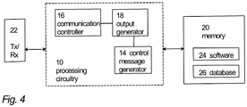
Figure 4 illustrates a block diagram of a structure of such an apparatus. The apparatus may be comprised in the user terminal or in the network node, e.g. the apparatus may form a chipset or a circuitry in the user terminal or network node. In some embodiments, the apparatus is the user terminal or the network node. The apparatus comprises aprocessing circuitry 10 comprising the at least one processor. Theprocessing circuitry 10 may comprise acommunication controller 16 configured to receive the drive status data and the fault log data. Thecommunication controller 16 may further be configured to, based on at least the received fault log data and device status data, to execute one or more fault tracing steps related to the drive, in order to try to solve the fault situation. The executing of at least one of the fault tracing steps may comprise, for example, outputting a drive related inquiry to a user and receiving a user response to the drive related inquiry, causing the running of one or more operational tests on the drive, requesting and receiving further drive related information from the drive via thelocal connection network 104, requesting and receiving further drive related information from theremote apparatus 109 via thecommunications network 106, generating and outputting a drive related checklist to the user in respect of the fault, generating and outputting a drive related question to the user in respect of the fault, and/or generating and outputting a suggestion for a corrective action to the user in respect of the fault (instead of or in addition to the drive, these steps may relate to the device the drive is controlling). - The
processing circuitry 10 may further comprise anoutput generator 18 configured to output a request (via an appropriate user interface, not shown inFig. 4 ) to the user, requesting the user to indicate whether or not the fault was corrected. Thecommunication controller 16 is configured to detect a user indication (via an appropriate user interface (e.g. keyboard, touch display, microphone), not shown inFig. 4 ) whether or not the drive fault was corrected. Thecommunication controller 16 is configured to execute at least one other or updated fault tracing steps related to the drive to try to solve the fault situation, if required. Alternatively/in addition, acontrol message generator 14 may be configured to cause transmission of the fault log data, the device status data, information on the executed fault tracing step(s), and other debugging data (such as user-entered debugging data) related to the drive to a remote apparatus (such as a cloud server), for further analysis of the fault. Despite of whether or not the fault was corrected, thecontrol message generator 14 may be configured to cause transmission of the fault log data, the device status data, the information on the executed fault tracing step(s), and the other debugging data to theremote apparatus 109 to be stored in a memory/database. At least part of that information may also be stored in an internal memory/database 26 of theapparatus 105. - The
processing circuitry 10 may comprise thecircuitries memory 20 may store one or morecomputer program products 24 comprising program instructions that specify the operation of thecircuitries memory 20 may further store adatabase 26 comprising definitions for downlink control channel signalling, for example. The apparatus may further comprise aradio interface 22 providing the apparatus with radio communication capability with the network elements. The radio interface may comprise a radio communication circuitry enabling wireless communications and comprise a radio frequency signal processing circuitry and a baseband signal processing circuitry. The baseband signal processing circuitry may be configured to carry out the functions of a transmitter and/or a receiver. In some embodiments, the radio interface may be connected to a remote radio head comprising at least an antenna and, in some embodiments, radio frequency signal processing in a remote location with respect to the base station. In such embodiments, the radio interface may carry out only some of radio frequency signal processing or no radio frequency signal processing at all. The connection between the radio interface and the remote radio head may be an analogue connection or a digital connection. In some embodiments, the radio interface may comprise a fixed communication circuitry enabling wired communications. - As used in this application, the term 'circuitry' refers to all of the following: (a) hardware-only circuit implementations such as implementations in only analog and/or digital circuitry; (b) combinations of circuits and software and/or firmware, such as (as applicable): (i) a combination of processor(s) or processor cores; or (ii) portions of processor(s)/software including digital signal processor(s), software, and at least one memory that work together to cause an apparatus to perform specific functions; and (c) circuits, such as a microprocessor(s) or a portion of a microprocessor(s), that require software or firmware for operation, even if the software or firmware is not physically present.
- This definition of 'circuitry' applies to all uses of this term in this application. As a further example, as used in this application, the term "circuitry" would also cover an implementation of merely a processor (or multiple processors) or portion of a processor, e.g. one core of a multi-core processor, and its (or their) accompanying software and/or firmware. The term "circuitry" would also cover, for example and if applicable to the particular element, a baseband integrated circuit, an application-specific integrated circuit (ASIC), and/or a field-programmable grid array (FPGA) circuit for the apparatus according to an embodiment of the invention.
- The processes or methods described above in connection with
Figures 1 to 4 may also be carried out in the form of one or more computer process defined by one or more computer programs. The computer program shall be considered to encompass also a module of a computer programs, e.g. the above-described processes may be carried out as a program module of a larger algorithm or a computer process. The computer program(s) may be in source code form, object code form, or in some intermediate form, and it may be stored in a carrier, which may be any entity or device capable of carrying the program. Such carriers include transitory and/or non-transitory computer media, e.g. a record medium, computer memory, read-only memory, electrical carrier signal, telecommunications signal, and software distribution package. Depending on the processing power needed, the computer program may be executed in a single electronic digital processing unit or it may be distributed amongst a number of processing units. - The present invention is applicable to cellular or mobile communication systems defined above but also to other suitable communication systems. The protocols used, the specifications of cellular communication systems, their network elements, and terminal devices develop rapidly. Such development may require extra changes to the described embodiments. Therefore, all words and expressions should be interpreted broadly and they are intended to illustrate, not to restrict, the embodiment.
- In addition to a drive/frequency converter, an embodiment may also be applicable to other automated power conversion devices such as AC/DC modules, DC/AC modules, DC/DC modules, programmable logic controllers (PLC), switches, motion controllers, motion drives, servo motors, soft starters, robotics, cars, heavy equipment, and/or any other devices used for industrial automation.
- It will be obvious to a person skilled in the art that, as the technology advances, the inventive concept can be implemented in various ways. The invention and its embodiments are not limited to the examples described above but may vary within the scope of the claims.
Claims (15)
- A computerized method for fault management of an automated power conversion device, the method comprising
receiving, in a computing apparatus, at least device fault log data and device status data from the automated power conversion device via a local connection network;
based on at least the received data, executing, in the computing apparatus, one or more fault tracing steps related to the device,
wherein a fault tracing step comprises- outputting a device related inquiry to a user and receiving a user response to the device related inquiry,- causing the running of one or more operational tests on the device,- requesting and receiving further device related information from the device via the local connection network,- requesting and receiving further device related information from a remote apparatus via a communications network,- generating and outputting a device related checklist to the user in respect of the fault,- generating and outputting a device related question to the user in respect of the fault, and- generating and outputting a suggestion for a corrective action to the user in respect of the fault;wherein the device status data comprises device identification data and device related information on one or more of power-on time, motor running hours, fan running hours, estimation of direct current link capacitor lifetime, load current histogram, ambient temperature, insulated gate bipolar transistor temperature, control board temperature, frequency, direct current link voltage and motor current. - A method according to claim 1, wherein the method comprises
detecting, in the computing apparatus, a user input indicating that the fault was not corrected, wherein the method further comprises
causing, in the computing apparatus, transmission of the fault log data, the device status data, information on an executed fault tracing step, and optionally other debugging data regarding the device, to the remote apparatus, for further analysis of the fault. - A method according to claim 1 or 2, wherein the method comprises requesting, in the computing apparatus, the user to indicate to the computing apparatus if the fault was corrected.
- A method according to any one of the preceding claims, wherein a fault tracing step to be executed is selected in the computing apparatus based on information obtained from one or more previously executed fault tracing steps.
- A method according to any one of the preceding claims, wherein a fault tracing step to be executed is selected in the computing apparatus based on information stored in at least one of the computing apparatus, the remote apparatus, and the device.
- A method according to any one of the preceding claims, wherein a fault tracing step to be executed is selected in the computing apparatus based on user-entered information.
- A method according to any of the preceding claims, wherein the fault tracing step to be executed is dynamically customized for at least one of
the device, and
the operational fault of the device. - A method according to any of the preceding claims, wherein the method comprises causing storing, in a memory, associated information on one or more of
the suggestion for the corrective action;
whether or not the fault was corrected;
the fault tracing step,
the fault log data,
the device status data,
the further device related information,
the device related inquiry and the user response,
the operational test,
a result of the operational test,
the device related checklist,
the device related question,
user-entered information,
other debugging data;
a further fault analysis, and
a result of the further fault analysis. - A method according to claim 8, wherein the method comprises in the computing apparatus
retrieving the stored associated information from the memory; and
utilizing the retrieved information as source information when executing a subsequent fault tracing step related to the same or different device. - A method according to claim 2 or 8, wherein the other debugging data comprises user-entered debugging data.
- A method according to any of the preceding claims, wherein
the fault log data comprises a fault code recorded in the device when the fault occurred; and
the device status data comprises device identification information, and internal variables and key performance indicators on the condition of the device. - A method according to any of the preceding claims, wherein the computing apparatus comprises a mobile device and the automated power conversion device comprises a drive.
- An apparatus comprising
at least one processor; and
at least one memory including a computer program code, wherein the at least one memory and the computer program code are configured, with the at least one processor, to cause the apparatus to perform any of the method steps of claims 1 to 12. - A computer program product embodied on a distribution medium readable by a computer and comprising program instructions which, when loaded into an apparatus, execute the method according to any preceding claim 1 to 12.
- A system comprising a drive and a local connection network, wherein the system further comprises the apparatus of claim 13.
Priority Applications (1)
| Application Number | Priority Date | Filing Date | Title |
|---|---|---|---|
| EP17150819.5A EP3346384B1 (en) | 2017-01-10 | 2017-01-10 | Industrial device fault management in a communications system |
Applications Claiming Priority (1)
| Application Number | Priority Date | Filing Date | Title |
|---|---|---|---|
| EP17150819.5A EP3346384B1 (en) | 2017-01-10 | 2017-01-10 | Industrial device fault management in a communications system |
Publications (2)
| Publication Number | Publication Date |
|---|---|
| EP3346384A1 EP3346384A1 (en) | 2018-07-11 |
| EP3346384B1 true EP3346384B1 (en) | 2020-03-04 |
Family
ID=57796169
Family Applications (1)
| Application Number | Title | Priority Date | Filing Date |
|---|---|---|---|
| EP17150819.5A Active EP3346384B1 (en) | 2017-01-10 | 2017-01-10 | Industrial device fault management in a communications system |
Country Status (1)
| Country | Link |
|---|---|
| EP (1) | EP3346384B1 (en) |
Families Citing this family (1)
| Publication number | Priority date | Publication date | Assignee | Title |
|---|---|---|---|---|
| CN114339843B (en) * | 2020-09-27 | 2023-08-15 | 中国移动通信集团浙江有限公司 | Anchor point problem identification method and device based on network coverage |
Family Cites Families (4)
| Publication number | Priority date | Publication date | Assignee | Title |
|---|---|---|---|---|
| KR20120099951A (en) * | 2011-03-02 | 2012-09-12 | 삼성전자주식회사 | Method and system for providing after service of electronic device using mobile terminal |
| WO2015171581A1 (en) * | 2014-05-07 | 2015-11-12 | Siemens Healthcare Diagnostics Inc. | Intelligent service assistant - instrument side software client |
| US9645880B2 (en) * | 2014-09-11 | 2017-05-09 | Sap Se | Supportability framework for mobile software applications |
| EP3101777B8 (en) * | 2015-06-04 | 2018-11-14 | ABB Schweiz AG | Communicating of frequency converter parameters |
-
2017
- 2017-01-10 EP EP17150819.5A patent/EP3346384B1/en active Active
Non-Patent Citations (1)
| Title |
|---|
| None * |
Also Published As
| Publication number | Publication date |
|---|---|
| EP3346384A1 (en) | 2018-07-11 |
Similar Documents
| Publication | Publication Date | Title |
|---|---|---|
| US10895871B2 (en) | Method and system for automatically generating interactive wiring diagram in an industrial automation environment | |
| US20100256794A1 (en) | Cloud computing for a manufacturing execution system | |
| US10002008B2 (en) | Manual, a method, apparatus and a computer program product for configuring a frequency converter | |
| US10375208B2 (en) | Optimisation of industrial device parameters in a communications system | |
| WO2010120442A2 (en) | Cloud computing as a basis for equipment health monitoring service | |
| US20160360394A1 (en) | Communicating of frequency converter parameters | |
| US20170168473A1 (en) | Signalling of specification information on an industrial device | |
| US10572162B2 (en) | Storing application information on an automation device | |
| CN101867956A (en) | Monitoring method, device and system of base station and corollary equipment thereof | |
| EP3346384B1 (en) | Industrial device fault management in a communications system | |
| US9787947B2 (en) | Surveillance system with intelligently interchangeable cameras | |
| CN111885892B (en) | Heat dissipation control method, system and equipment of power adapter and readable storage medium | |
| EP3220608B1 (en) | Retrieval of industrial device data in a communications system | |
| EP3920545B1 (en) | Wireless communication for industrial automation | |
| EP3480670B1 (en) | Method for remote support of electric drive apparatus | |
| US10554332B2 (en) | Communicating industrial device data in a communications system | |
| JP2018007503A (en) | Server device, driving device, terminal equipment, program, and method | |
| CN110324398B (en) | Method for remotely supporting an electric drive device | |
| EP2745547B1 (en) | App driven base station man-machine interface | |
| EP3101815B1 (en) | Signalling between a frequency converter and a terminal device | |
| CN107925700A (en) | Change the data set in shared communication environment | |
| KR20140041976A (en) | Method of monitoring power device | |
| CN116915840A (en) | Communication method, terminal device, server, communication system and electronic device | |
| AU2010236934B2 (en) | Cloud computing as a basis for equipment health monitoring service | |
| CN112333089A (en) | Intelligent gateway and method for industrial preventive maintenance |
Legal Events
| Date | Code | Title | Description |
|---|---|---|---|
| PUAI | Public reference made under article 153(3) epc to a published international application that has entered the european phase |
Free format text: ORIGINAL CODE: 0009012 |
|
| STAA | Information on the status of an ep patent application or granted ep patent |
Free format text: STATUS: THE APPLICATION HAS BEEN PUBLISHED |
|
| AK | Designated contracting states |
Kind code of ref document: A1 Designated state(s): AL AT BE BG CH CY CZ DE DK EE ES FI FR GB GR HR HU IE IS IT LI LT LU LV MC MK MT NL NO PL PT RO RS SE SI SK SM TR |
|
| AX | Request for extension of the european patent |
Extension state: BA ME |
|
| STAA | Information on the status of an ep patent application or granted ep patent |
Free format text: STATUS: REQUEST FOR EXAMINATION WAS MADE |
|
| RAP1 | Party data changed (applicant data changed or rights of an application transferred) |
Owner name: ABB SCHWEIZ AG |
|
| 17P | Request for examination filed |
Effective date: 20180928 |
|
| RBV | Designated contracting states (corrected) |
Designated state(s): AL AT BE BG CH CY CZ DE DK EE ES FI FR GB GR HR HU IE IS IT LI LT LU LV MC MK MT NL NO PL PT RO RS SE SI SK SM TR |
|
| STAA | Information on the status of an ep patent application or granted ep patent |
Free format text: STATUS: EXAMINATION IS IN PROGRESS |
|
| 17Q | First examination report despatched |
Effective date: 20181129 |
|
| GRAP | Despatch of communication of intention to grant a patent |
Free format text: ORIGINAL CODE: EPIDOSNIGR1 |
|
| STAA | Information on the status of an ep patent application or granted ep patent |
Free format text: STATUS: GRANT OF PATENT IS INTENDED |
|
| INTG | Intention to grant announced |
Effective date: 20190711 |
|
| GRAS | Grant fee paid |
Free format text: ORIGINAL CODE: EPIDOSNIGR3 |
|
| GRAA | (expected) grant |
Free format text: ORIGINAL CODE: 0009210 |
|
| STAA | Information on the status of an ep patent application or granted ep patent |
Free format text: STATUS: THE PATENT HAS BEEN GRANTED |
|
| AK | Designated contracting states |
Kind code of ref document: B1 Designated state(s): AL AT BE BG CH CY CZ DE DK EE ES FI FR GB GR HR HU IE IS IT LI LT LU LV MC MK MT NL NO PL PT RO RS SE SI SK SM TR |
|
| REG | Reference to a national code |
Ref country code: GB Ref legal event code: FG4D |
|
| REG | Reference to a national code |
Ref country code: CH Ref legal event code: EP |
|
| REG | Reference to a national code |
Ref country code: AT Ref legal event code: REF Ref document number: 1241185 Country of ref document: AT Kind code of ref document: T Effective date: 20200315 |
|
| REG | Reference to a national code |
Ref country code: DE Ref legal event code: R096 Ref document number: 602017012422 Country of ref document: DE |
|
| REG | Reference to a national code |
Ref country code: IE Ref legal event code: FG4D |
|
| PG25 | Lapsed in a contracting state [announced via postgrant information from national office to epo] |
Ref country code: RS Free format text: LAPSE BECAUSE OF FAILURE TO SUBMIT A TRANSLATION OF THE DESCRIPTION OR TO PAY THE FEE WITHIN THE PRESCRIBED TIME-LIMIT Effective date: 20200304 Ref country code: FI Free format text: LAPSE BECAUSE OF FAILURE TO SUBMIT A TRANSLATION OF THE DESCRIPTION OR TO PAY THE FEE WITHIN THE PRESCRIBED TIME-LIMIT Effective date: 20200304 Ref country code: NO Free format text: LAPSE BECAUSE OF FAILURE TO SUBMIT A TRANSLATION OF THE DESCRIPTION OR TO PAY THE FEE WITHIN THE PRESCRIBED TIME-LIMIT Effective date: 20200604 |
|
| REG | Reference to a national code |
Ref country code: NL Ref legal event code: MP Effective date: 20200304 |
|
| PG25 | Lapsed in a contracting state [announced via postgrant information from national office to epo] |
Ref country code: GR Free format text: LAPSE BECAUSE OF FAILURE TO SUBMIT A TRANSLATION OF THE DESCRIPTION OR TO PAY THE FEE WITHIN THE PRESCRIBED TIME-LIMIT Effective date: 20200605 Ref country code: BG Free format text: LAPSE BECAUSE OF FAILURE TO SUBMIT A TRANSLATION OF THE DESCRIPTION OR TO PAY THE FEE WITHIN THE PRESCRIBED TIME-LIMIT Effective date: 20200604 Ref country code: LV Free format text: LAPSE BECAUSE OF FAILURE TO SUBMIT A TRANSLATION OF THE DESCRIPTION OR TO PAY THE FEE WITHIN THE PRESCRIBED TIME-LIMIT Effective date: 20200304 Ref country code: SE Free format text: LAPSE BECAUSE OF FAILURE TO SUBMIT A TRANSLATION OF THE DESCRIPTION OR TO PAY THE FEE WITHIN THE PRESCRIBED TIME-LIMIT Effective date: 20200304 Ref country code: HR Free format text: LAPSE BECAUSE OF FAILURE TO SUBMIT A TRANSLATION OF THE DESCRIPTION OR TO PAY THE FEE WITHIN THE PRESCRIBED TIME-LIMIT Effective date: 20200304 |
|
| REG | Reference to a national code |
Ref country code: LT Ref legal event code: MG4D |
|
| PG25 | Lapsed in a contracting state [announced via postgrant information from national office to epo] |
Ref country code: NL Free format text: LAPSE BECAUSE OF FAILURE TO SUBMIT A TRANSLATION OF THE DESCRIPTION OR TO PAY THE FEE WITHIN THE PRESCRIBED TIME-LIMIT Effective date: 20200304 |
|
| PG25 | Lapsed in a contracting state [announced via postgrant information from national office to epo] |
Ref country code: RO Free format text: LAPSE BECAUSE OF FAILURE TO SUBMIT A TRANSLATION OF THE DESCRIPTION OR TO PAY THE FEE WITHIN THE PRESCRIBED TIME-LIMIT Effective date: 20200304 Ref country code: LT Free format text: LAPSE BECAUSE OF FAILURE TO SUBMIT A TRANSLATION OF THE DESCRIPTION OR TO PAY THE FEE WITHIN THE PRESCRIBED TIME-LIMIT Effective date: 20200304 Ref country code: ES Free format text: LAPSE BECAUSE OF FAILURE TO SUBMIT A TRANSLATION OF THE DESCRIPTION OR TO PAY THE FEE WITHIN THE PRESCRIBED TIME-LIMIT Effective date: 20200304 Ref country code: SM Free format text: LAPSE BECAUSE OF FAILURE TO SUBMIT A TRANSLATION OF THE DESCRIPTION OR TO PAY THE FEE WITHIN THE PRESCRIBED TIME-LIMIT Effective date: 20200304 Ref country code: PT Free format text: LAPSE BECAUSE OF FAILURE TO SUBMIT A TRANSLATION OF THE DESCRIPTION OR TO PAY THE FEE WITHIN THE PRESCRIBED TIME-LIMIT Effective date: 20200729 Ref country code: EE Free format text: LAPSE BECAUSE OF FAILURE TO SUBMIT A TRANSLATION OF THE DESCRIPTION OR TO PAY THE FEE WITHIN THE PRESCRIBED TIME-LIMIT Effective date: 20200304 Ref country code: SK Free format text: LAPSE BECAUSE OF FAILURE TO SUBMIT A TRANSLATION OF THE DESCRIPTION OR TO PAY THE FEE WITHIN THE PRESCRIBED TIME-LIMIT Effective date: 20200304 Ref country code: CZ Free format text: LAPSE BECAUSE OF FAILURE TO SUBMIT A TRANSLATION OF THE DESCRIPTION OR TO PAY THE FEE WITHIN THE PRESCRIBED TIME-LIMIT Effective date: 20200304 Ref country code: IS Free format text: LAPSE BECAUSE OF FAILURE TO SUBMIT A TRANSLATION OF THE DESCRIPTION OR TO PAY THE FEE WITHIN THE PRESCRIBED TIME-LIMIT Effective date: 20200704 |
|
| REG | Reference to a national code |
Ref country code: AT Ref legal event code: MK05 Ref document number: 1241185 Country of ref document: AT Kind code of ref document: T Effective date: 20200304 |
|
| REG | Reference to a national code |
Ref country code: DE Ref legal event code: R097 Ref document number: 602017012422 Country of ref document: DE |
|
| PLBE | No opposition filed within time limit |
Free format text: ORIGINAL CODE: 0009261 |
|
| STAA | Information on the status of an ep patent application or granted ep patent |
Free format text: STATUS: NO OPPOSITION FILED WITHIN TIME LIMIT |
|
| PG25 | Lapsed in a contracting state [announced via postgrant information from national office to epo] |
Ref country code: IT Free format text: LAPSE BECAUSE OF FAILURE TO SUBMIT A TRANSLATION OF THE DESCRIPTION OR TO PAY THE FEE WITHIN THE PRESCRIBED TIME-LIMIT Effective date: 20200304 Ref country code: DK Free format text: LAPSE BECAUSE OF FAILURE TO SUBMIT A TRANSLATION OF THE DESCRIPTION OR TO PAY THE FEE WITHIN THE PRESCRIBED TIME-LIMIT Effective date: 20200304 Ref country code: AT Free format text: LAPSE BECAUSE OF FAILURE TO SUBMIT A TRANSLATION OF THE DESCRIPTION OR TO PAY THE FEE WITHIN THE PRESCRIBED TIME-LIMIT Effective date: 20200304 |
|
| 26N | No opposition filed |
Effective date: 20201207 |
|
| PG25 | Lapsed in a contracting state [announced via postgrant information from national office to epo] |
Ref country code: SI Free format text: LAPSE BECAUSE OF FAILURE TO SUBMIT A TRANSLATION OF THE DESCRIPTION OR TO PAY THE FEE WITHIN THE PRESCRIBED TIME-LIMIT Effective date: 20200304 Ref country code: PL Free format text: LAPSE BECAUSE OF FAILURE TO SUBMIT A TRANSLATION OF THE DESCRIPTION OR TO PAY THE FEE WITHIN THE PRESCRIBED TIME-LIMIT Effective date: 20200304 |
|
| PG25 | Lapsed in a contracting state [announced via postgrant information from national office to epo] |
Ref country code: MC Free format text: LAPSE BECAUSE OF FAILURE TO SUBMIT A TRANSLATION OF THE DESCRIPTION OR TO PAY THE FEE WITHIN THE PRESCRIBED TIME-LIMIT Effective date: 20200304 |
|
| REG | Reference to a national code |
Ref country code: CH Ref legal event code: PL |
|
| PG25 | Lapsed in a contracting state [announced via postgrant information from national office to epo] |
Ref country code: LU Free format text: LAPSE BECAUSE OF NON-PAYMENT OF DUE FEES Effective date: 20210110 |
|
| REG | Reference to a national code |
Ref country code: BE Ref legal event code: MM Effective date: 20210131 |
|
| PG25 | Lapsed in a contracting state [announced via postgrant information from national office to epo] |
Ref country code: CH Free format text: LAPSE BECAUSE OF NON-PAYMENT OF DUE FEES Effective date: 20210131 Ref country code: LI Free format text: LAPSE BECAUSE OF NON-PAYMENT OF DUE FEES Effective date: 20210131 |
|
| PG25 | Lapsed in a contracting state [announced via postgrant information from national office to epo] |
Ref country code: IE Free format text: LAPSE BECAUSE OF NON-PAYMENT OF DUE FEES Effective date: 20210110 |
|
| PG25 | Lapsed in a contracting state [announced via postgrant information from national office to epo] |
Ref country code: BE Free format text: LAPSE BECAUSE OF NON-PAYMENT OF DUE FEES Effective date: 20210131 |
|
| PGFP | Annual fee paid to national office [announced via postgrant information from national office to epo] |
Ref country code: FR Payment date: 20230124 Year of fee payment: 7 |
|
| PGFP | Annual fee paid to national office [announced via postgrant information from national office to epo] |
Ref country code: GB Payment date: 20230119 Year of fee payment: 7 Ref country code: DE Payment date: 20230123 Year of fee payment: 7 |
|
| PG25 | Lapsed in a contracting state [announced via postgrant information from national office to epo] |
Ref country code: CY Free format text: LAPSE BECAUSE OF FAILURE TO SUBMIT A TRANSLATION OF THE DESCRIPTION OR TO PAY THE FEE WITHIN THE PRESCRIBED TIME-LIMIT Effective date: 20200304 |
|
| PG25 | Lapsed in a contracting state [announced via postgrant information from national office to epo] |
Ref country code: HU Free format text: LAPSE BECAUSE OF FAILURE TO SUBMIT A TRANSLATION OF THE DESCRIPTION OR TO PAY THE FEE WITHIN THE PRESCRIBED TIME-LIMIT; INVALID AB INITIO Effective date: 20170110 |