EP3933316A1 - A cooling appliance having an improved handle mechanism - Google Patents
A cooling appliance having an improved handle mechanism Download PDFInfo
- Publication number
- EP3933316A1 EP3933316A1 EP21176404.8A EP21176404A EP3933316A1 EP 3933316 A1 EP3933316 A1 EP 3933316A1 EP 21176404 A EP21176404 A EP 21176404A EP 3933316 A1 EP3933316 A1 EP 3933316A1
- Authority
- EP
- European Patent Office
- Prior art keywords
- door
- handle
- cooling appliance
- connecting tab
- locking mechanism
- Prior art date
- Legal status (The legal status is an assumption and is not a legal conclusion. Google has not performed a legal analysis and makes no representation as to the accuracy of the status listed.)
- Withdrawn
Links
- 238000001816 cooling Methods 0.000 title claims abstract description 33
- 230000000694 effects Effects 0.000 claims description 11
- 230000000063 preceeding effect Effects 0.000 claims 4
- 239000011111 cardboard Substances 0.000 description 2
- 238000012423 maintenance Methods 0.000 description 2
- 238000000034 method Methods 0.000 description 2
- 230000003247 decreasing effect Effects 0.000 description 1
- 230000001419 dependent effect Effects 0.000 description 1
- 230000008447 perception Effects 0.000 description 1
Images


Classifications
-
- E—FIXED CONSTRUCTIONS
- E05—LOCKS; KEYS; WINDOW OR DOOR FITTINGS; SAFES
- E05B—LOCKS; ACCESSORIES THEREFOR; HANDCUFFS
- E05B3/00—Fastening knobs or handles to lock or latch parts
-
- E—FIXED CONSTRUCTIONS
- E05—LOCKS; KEYS; WINDOW OR DOOR FITTINGS; SAFES
- E05B—LOCKS; ACCESSORIES THEREFOR; HANDCUFFS
- E05B1/00—Knobs or handles for wings; Knobs, handles, or press buttons for locks or latches on wings
- E05B1/0015—Knobs or handles which do not operate the bolt or lock, e.g. non-movable; Mounting thereof
-
- F—MECHANICAL ENGINEERING; LIGHTING; HEATING; WEAPONS; BLASTING
- F25—REFRIGERATION OR COOLING; COMBINED HEATING AND REFRIGERATION SYSTEMS; HEAT PUMP SYSTEMS; MANUFACTURE OR STORAGE OF ICE; LIQUEFACTION SOLIDIFICATION OF GASES
- F25D—REFRIGERATORS; COLD ROOMS; ICE-BOXES; COOLING OR FREEZING APPARATUS NOT OTHERWISE PROVIDED FOR
- F25D23/00—General constructional features
- F25D23/02—Doors; Covers
- F25D23/028—Details
Definitions
- the present invention relates to a cooling appliance, in particular to a cooling appliance having an improved handle mechanism.
- the cooling devices are provided with a wide variety of door handles.
- the handles contain many features so as to meet the demand of the customers. In the event of changing the location of the cooling appliance inside the kitchen or moving to a new house, the necessity of changing the swing direction of the door may arise. In such cases, the handle must be switched to the opposing side of the door. Such a procedure requires the attendance of a skilled worker which is unwanted as it causes additional costs.
- Another problem caused by the handles during transportation is that the handle generally protrudes outwards from the door therefore increasing the projectional area and therefore the volume of the cooling appliance. This additional increase in the volume increases the volume of the cooling appliance during transportation.
- KR20070065743A A prior art publication in the technical field of the present invention may be referred to as KR20070065743A among others, the document disclosing a cooling appliance having an handle having simplified assembly and structure.
- WO2015144247A1 A prior art publication in the technical field of the present invention may be referred to as WO2015144247A1 among others, the document disclosing a cooling appliance having a handle wherein the handle has a simplified assembly and structure.
- WO2016177428A1 A prior art publication in the technical field of the present invention may be referred to as WO2016177428A1 among others, the document relating to a handle assembly for use in a household assembly, in particular a cooling appliance.
- An objective of the present invention is to provide a handle having simplified assembly.
- Another objective of the present invention is to provide a handle helping reduce the volume of the card board boxes during the transport.
- Another objective of the present invention is to provide a handle wherein the handle is easy to assemble and disassemble but is impossible to remove from the door by accident.
- the method realized to achieve the aim of the present invention and disclosed in the first claim and the dependent claims comprises a cooling appliance.
- the cooling appliance comprises a body and a door pivotably attached onto the body between a closed and an open position.
- the handle is attached onto the door by a pair of supports wherein the supports are provided at the ends of the handle, distanced apart by a predetermined length. The length depends on the length of the handle.
- Each of the supports comprise at least a connecting tab.
- the support located above the other one comprises the first connecting tab.
- the other support comprises the second connecting tab.
- the connecting tabs extend away from the supports and are seated inside the seating members provided on the door.
- One of the supports in a preferred embodiment is located above with respect to the other one and comprises a locking mechanism.
- the locking mechanism can be switched to a locked position and an open position.
- the locking mechanism ensures that the handle, supports and the connecting tabs remain on the door.
- the open position the user may simply hold and pull the handle, releasing the handle from the door.
- the handle is attached to the door in a convenient manner which eliminates the need to call for a maintenance personal if the user needs to replace the handle to the opposing edge of the door.
- the locking mechanism comprises a first biasing means and a second biasing means wherein the first biasing means biases the first connecting tab towards the locked position.
- the second biasing means biases the second connecting tab towards the open position.
- the first connecting tab remains in balance between the said biasing means.
- the biasing means act on an end of the first connecting tab.
- the locking means comprises an element, which upon being activated by the user, effects on the biasing means and forces the locking mechanism towards the open position. Therefore, the handle can be removed from the door. By means of the element, the handle can be assembled and disassembled to and from the door conveniently.
- the locking mechanism comprises a link.
- the link passes through the first connecting tab and acts as a pivot or rotation point for the first connecting tab.
- the biasing means act on the first connecting tab and thanks to the link, the first connecting tab moves easily, changing the position of the locking mechanism towards the open position.
- the first connecting tab comprises a first lug configured to be seated inside a recess provided on the seating member.
- the first lug seats inside the recess during the locked position of the locking mechanism.
- the recess and the first lug provide a rigid structure.
- the second connecting tab comprises a second lug configured to be seated inside a recess provided on the seating member.
- the second lug seats inside the recess during the locked position of the locking mechanism.
- the recess and the second lug provide a rigid structure.
- the first lug and the second lug point away from each other with an angle almost equal to 180 degrees. Therefore, during the locked position, the first lug points upwards whereas the second lug points downwards while seated inside their respective recesses. This helps create a rigid handle and door assembly.
- the seating members are embedded inside the door.
- the handle can be attached onto the door in a convenient manner reducing maintenance related costs.
- Another advantageous effect provided by means of this invention is that the structure of the handle and the locking mechanism is simplified reducing the overall costs of the cooling appliance.
- the present invention relates to a cooling appliance comprising; a body and a door (1) attached to the body between a closed position and an open position; a handle (2) attached onto an edge of the door (1) having a pair of supports (3) distanced apart from one another on the handle (2);
- first connecting tab (4) and a second connecting tab (5) extending away from each of the supports (3); a pair of seating members (6) provided on the door (1) into which the connecting tabs (4,5) are placed.
- the present invention relates to a cooling appliance wherein one of the supports (3) comprises a locking mechanism (7) that is configured to releasable attach the handle onto the door (1) between a locked and an open position.
- the handle (2) is attached to an edge of the door (1) be means of the pair supports (3) provided on the handle (2).
- the supports (3) are at the ends of the handle (2) wherein the handle (2) is in the shape of a bar.
- the connecting tabs (4,5) are provided on the supports (3) and extend away from the supports (3) towards the seating members (6).
- the handle (2) is attached to the door (1) by seating the connecting tabs (4,5) inside the seating members (6).
- One of the supports (3) comprises the locking mechanism (7).
- the locking mechanism (7) is configured to be activate the connecting tabs (4,5) which upon being activated releases the connecting tabs (4,5) from the seating members (6).
- the handle (2) can be attached onto the door (1) in a convenient manner.
- Another advantageous effect provided by means of the locking mechanism (7) is that the handle (2) can be disassembled during transportation, decreasing the volume of the box and therefore transportation related costs.
- the present invention relates to a cooling appliance wherein the locking mechanism (7) comprises a first biasing means (8) and a second biasing means (9), biasing the first connecting tab (4) to the locked position and the open position respectively and an element (10) which upon pressed or pushed is configured to effect on the biasing means (8,9) so as to force the locking mechanism (7) towards the open position.
- the first connecting tab (4) is biased by means of the first biasing means (8) and the second biasing means (9) and is in balance.
- the first biasing means (8) biases the first connecting tab (4) to the locked position and the second biasing means (9) biases the first connecting tab (4) to the open position.
- the element (10) is provided on the support (3) and effects the biasing means (8,9) upon being pressed or pushed.
- the biasing means (8,9) are preferably helical springs. Upon being pressed or pushed, the element (10) compresses the first biasing means (8) more than it does compress the second biasing means (9), releasing the first connecting tab (4) from the seating member (6). By means of the element (10), the users can easily remove the handle (2) from the door (1).
- the present invention relates to a cooling appliance wherein the locking mechanism (7) comprises a link (11) allowing the first connecting tab (4) to pivot or rotate.
- the link (11) is used as a pivot or a rotation point for the first connecting tab (4) which in turn facilitates the release of the handle (2) from the seating members (6).
- the present invention relates to a cooling appliance wherein the first connecting tab (4) comprises a first lug (12) configured to be seated into a recess provided on the seating member (6).
- the seating member (6) is provided with the recess wherein the first connecting tab (4) is seated by means of the first lug (12).
- the first lug (12) eliminates the possibility of accidental removal of the first connecting tab (4) from the recess and therefore form the seating member (6).
- the present invention relates to a cooling appliance wherein the second connecting tab (5) comprises a second lug (13) configured to be seated into a recess provided on the seating member (6).
- the seating member (6) is provided with the recess wherein the second connecting tab (5) is seated by means of the second lug (13).
- the second lug (13) eliminates the possibility of accidental removal of the second connecting tab (5) from the recess and therefore form the seating member (6).
- the present invention relates to a cooling appliance wherein the first lug (12) and the second lug (13) points away from each other.
- the lugs (12,13) point away from each other upon being seated inside the recesses provided on seating members (6).
- the lugs (12,13) point away from each other by 180 degrees.
- the present invention relates to a cooling appliance wherein the seating members (6) are embedded inside the door (1).
- the seating members (6) form a flush surface with the front panel of the door (1) which helps increase quality perception of the product.
- Another advantageous effect provided by means of the locking means (7) is that the handle (2) can be easily removed from the door (1).
- Another advantageous effect provided by means of the locking means (7) is that the use of small details that are prone to wear out or even break in time such as clips, teeth or tabs are not used.
- handle (2) being easily disassembled from the door (1) provides the handle (2) to be stored inside the cooling appliance during transport, which in turn greatly reduces the dimensions of the card board box containing the cooling appliance and therefore the transportation related costs.
Landscapes
- Engineering & Computer Science (AREA)
- Mechanical Engineering (AREA)
- Chemical & Material Sciences (AREA)
- Combustion & Propulsion (AREA)
- Physics & Mathematics (AREA)
- Thermal Sciences (AREA)
- General Engineering & Computer Science (AREA)
- Refrigerator Housings (AREA)
- Lock And Its Accessories (AREA)
Abstract
The present invention relates to a cooling appliance comprising; a body and a door (1) attached to the body between a closed position and an open position; a handle (2) attached onto an edge of the door (1) having a pair of supports (3) distanced apart from one another on the handle (2);a first connecting tab (4) and a second connecting tab (5) extending away from each of the supports (3); a pair of seating members (6) provided on the door (1) into which the connecting tabs (4,5) are placed, wherein one of the supports (3) comprises a locking mechanism (7) configured to releasable attach the handle onto the door (1) between a locked and an open position.
Description
- The present invention relates to a cooling appliance, in particular to a cooling appliance having an improved handle mechanism.
- The cooling devices are provided with a wide variety of door handles. The handles contain many features so as to meet the demand of the customers. In the event of changing the location of the cooling appliance inside the kitchen or moving to a new house, the necessity of changing the swing direction of the door may arise. In such cases, the handle must be switched to the opposing side of the door. Such a procedure requires the attendance of a skilled worker which is unwanted as it causes additional costs. Another problem caused by the handles during transportation is that the handle generally protrudes outwards from the door therefore increasing the projectional area and therefore the volume of the cooling appliance. This additional increase in the volume increases the volume of the cooling appliance during transportation.
- A prior art publication in the technical field of the present invention may be referred to as
KR20070065743A - A prior art publication in the technical field of the present invention may be referred to as
US2010005631A1 among others, the document disclosing a cooling appliance having a handle wherein the handle is mounted to a front face of the door through interengagement of fasteners with clips - A prior art publication in the technical field of the present invention may be referred to as
WO2015144247A1 among others, the document disclosing a cooling appliance having a handle wherein the handle has a simplified assembly and structure. - A prior art publication in the technical field of the present invention may be referred to as
WO2016177428A1 among others, the document relating to a handle assembly for use in a household assembly, in particular a cooling appliance. - An objective of the present invention is to provide a handle having simplified assembly.
- Another objective of the present invention is to provide a handle helping reduce the volume of the card board boxes during the transport.
- Another objective of the present invention is to provide a handle wherein the handle is easy to assemble and disassemble but is impossible to remove from the door by accident.
- The method realized to achieve the aim of the present invention and disclosed in the first claim and the dependent claims comprises a cooling appliance. The cooling appliance comprises a body and a door pivotably attached onto the body between a closed and an open position. The handle is attached onto the door by a pair of supports wherein the supports are provided at the ends of the handle, distanced apart by a predetermined length. The length depends on the length of the handle. Each of the supports, comprise at least a connecting tab. The support located above the other one comprises the first connecting tab. The other support comprises the second connecting tab. The connecting tabs extend away from the supports and are seated inside the seating members provided on the door. One of the supports, in a preferred embodiment is located above with respect to the other one and comprises a locking mechanism. The locking mechanism can be switched to a locked position and an open position. During locked position, the locking mechanism ensures that the handle, supports and the connecting tabs remain on the door. During the open position, the user may simply hold and pull the handle, releasing the handle from the door. By means of the locking means, the handle is attached to the door in a convenient manner which eliminates the need to call for a maintenance personal if the user needs to replace the handle to the opposing edge of the door.
- In an embodiment of the invention, the locking mechanism comprises a first biasing means and a second biasing means wherein the first biasing means biases the first connecting tab towards the locked position. On the other hand, the second biasing means biases the second connecting tab towards the open position. The first connecting tab remains in balance between the said biasing means. The biasing means act on an end of the first connecting tab. The locking means comprises an element, which upon being activated by the user, effects on the biasing means and forces the locking mechanism towards the open position. Therefore, the handle can be removed from the door. By means of the element, the handle can be assembled and disassembled to and from the door conveniently.
- In an embodiment of the invention, the locking mechanism comprises a link. The link passes through the first connecting tab and acts as a pivot or rotation point for the first connecting tab. The biasing means act on the first connecting tab and thanks to the link, the first connecting tab moves easily, changing the position of the locking mechanism towards the open position.
- In an embodiment of the invention, the first connecting tab comprises a first lug configured to be seated inside a recess provided on the seating member. The first lug seats inside the recess during the locked position of the locking mechanism. The recess and the first lug provide a rigid structure.
- In an embodiment of the invention, the second connecting tab comprises a second lug configured to be seated inside a recess provided on the seating member. The second lug seats inside the recess during the locked position of the locking mechanism. The recess and the second lug provide a rigid structure.
- In an embodiment of the invention, the first lug and the second lug point away from each other with an angle almost equal to 180 degrees. Therefore, during the locked position, the first lug points upwards whereas the second lug points downwards while seated inside their respective recesses. This helps create a rigid handle and door assembly.
- In an embodiment of the invention, the seating members are embedded inside the door.
- By means of the present invention, the handle can be attached onto the door in a convenient manner reducing maintenance related costs.
- Another advantageous effect provided by means of this invention is that the structure of the handle and the locking mechanism is simplified reducing the overall costs of the cooling appliance.
- The drawings are not meant to delimit the scope of protection as identified in the claims nor should they be referred to alone in an effort to interpret the scope identified in the claims without recourse to the technical disclosure in the description of the present invention.
-
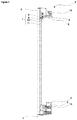
Figure 1 - is a perspective view of the cooling appliance -
Figure 2 - is an isolated view of the handle along dashed A-A lines inFigure 1 wherein the locking mechanism is in locked position -
Figure 3 - is an isolated view of the handle along dashed A-A lines inFigure 1 wherein the locking mechanism is in open position - The following numerals are assigned to different parts demonstrated in the drawings and referred to in the present detailed description of the invention:
- 1. Door
- 2. Handle
- 3. Support
- 4. First connecting tab
- 5. Second connecting tab
- 6. Seating member
- 7. Locking mechanism
- 8. First biasing means
- 9. Second biasing means
- 10. Element
- 11. Link
- 12. First lug
- 13. Second lug
- The present invention relates to a cooling appliance comprising; a body and a door (1) attached to the body between a closed position and an open position; a handle (2) attached onto an edge of the door (1) having a pair of supports (3) distanced apart from one another on the handle (2);
- a first connecting tab (4) and a second connecting tab (5) extending away from each of the supports (3); a pair of seating members (6) provided on the door (1) into which the connecting tabs (4,5) are placed.
- The present invention relates to a cooling appliance wherein one of the supports (3) comprises a locking mechanism (7) that is configured to releasable attach the handle onto the door (1) between a locked and an open position. The handle (2) is attached to an edge of the door (1) be means of the pair supports (3) provided on the handle (2). The supports (3) are at the ends of the handle (2) wherein the handle (2) is in the shape of a bar. The connecting tabs (4,5) are provided on the supports (3) and extend away from the supports (3) towards the seating members (6). The handle (2) is attached to the door (1) by seating the connecting tabs (4,5) inside the seating members (6). One of the supports (3) comprises the locking mechanism (7). The locking mechanism (7) is configured to be activate the connecting tabs (4,5) which upon being activated releases the connecting tabs (4,5) from the seating members (6). By means of the locking means (7), the handle (2) can be attached onto the door (1) in a convenient manner. Another advantageous effect provided by means of the locking mechanism (7) is that the handle (2) can be disassembled during transportation, decreasing the volume of the box and therefore transportation related costs.
- The present invention relates to a cooling appliance wherein the locking mechanism (7) comprises a first biasing means (8) and a second biasing means (9), biasing the first connecting tab (4) to the locked position and the open position respectively and an element (10) which upon pressed or pushed is configured to effect on the biasing means (8,9) so as to force the locking mechanism (7) towards the open position. The first connecting tab (4) is biased by means of the first biasing means (8) and the second biasing means (9) and is in balance. The first biasing means (8) biases the first connecting tab (4) to the locked position and the second biasing means (9) biases the first connecting tab (4) to the open position. The element (10) is provided on the support (3) and effects the biasing means (8,9) upon being pressed or pushed. The biasing means (8,9) are preferably helical springs. Upon being pressed or pushed, the element (10) compresses the first biasing means (8) more than it does compress the second biasing means (9), releasing the first connecting tab (4) from the seating member (6). By means of the element (10), the users can easily remove the handle (2) from the door (1).
- The present invention relates to a cooling appliance wherein the locking mechanism (7) comprises a link (11) allowing the first connecting tab (4) to pivot or rotate. The link (11) is used as a pivot or a rotation point for the first connecting tab (4) which in turn facilitates the release of the handle (2) from the seating members (6).
- The present invention relates to a cooling appliance wherein the first connecting tab (4) comprises a first lug (12) configured to be seated into a recess provided on the seating member (6). The seating member (6) is provided with the recess wherein the first connecting tab (4) is seated by means of the first lug (12). The first lug (12) eliminates the possibility of accidental removal of the first connecting tab (4) from the recess and therefore form the seating member (6).
- The present invention relates to a cooling appliance wherein the second connecting tab (5) comprises a second lug (13) configured to be seated into a recess provided on the seating member (6). The seating member (6) is provided with the recess wherein the second connecting tab (5) is seated by means of the second lug (13). The second lug (13) eliminates the possibility of accidental removal of the second connecting tab (5) from the recess and therefore form the seating member (6).
- The present invention relates to a cooling appliance wherein the first lug (12) and the second lug (13) points away from each other. The lugs (12,13) point away from each other upon being seated inside the recesses provided on seating members (6). In a preferred embodiment, the lugs (12,13) point away from each other by 180 degrees. By means of the lugs (12,13) pointing away from each, the handle (2) can be attached onto the door (1) in a robust manner.
- The present invention relates to a cooling appliance wherein the seating members (6) are embedded inside the door (1). The seating members (6) form a flush surface with the front panel of the door (1) which helps increase quality perception of the product.
- An advantageous effect provided by means of the locking means (7) is that the handle (2) can be assembled onto the door (1) in a convenient manner.
- Another advantageous effect provided by means of the locking means (7) is that the handle (2) can be easily removed from the door (1).
- Another advantageous effect provided by means of the locking means (7) is that the handle (2) is rigidly attached onto the door (1), eliminating the possibility of accidental disconnecting of the handle (2) from the door (1), providing safety for the children.
- Another advantageous effect provided by means of the locking means (7) is that the use of small details that are prone to wear out or even break in time such as clips, teeth or tabs are not used.
- Another advantageous effect provided by means of handle (2) being easily disassembled from the door (1) provides the handle (2) to be stored inside the cooling appliance during transport, which in turn greatly reduces the dimensions of the card board box containing the cooling appliance and therefore the transportation related costs.
Claims (7)
- A cooling appliance comprising;
a body and a door (1) attached to the body between a closed position and an open position;
a handle (2) attached onto an edge of the door (1) having a pair of supports (3) distanced apart from one another on the handle (2);
a first connecting tab (4) and a second connecting tab (5) extending away from each of the supports (3);
a pair of seating members (6) provided on the door (1) into which the connecting tabs (4,5) are placed;
characterized in that
one of the supports (3) comprises a locking mechanism (7) configured to releasable attach the handle onto the door (1) between a locked and an open position. - A cooling appliance according to claim 1, characterized in that the locking mechanism (7) comprises a first biasing means (8) and a second biasing means (9), biasing the first connecting tab (4) to the locked position and the open position respectively and an element (10) which upon pressed or pushed is configured to effect on biasing means (8,9) so as to force the locking mechanism (7) towards the open position.
- A cooling appliance according to any preceeding claim, characterized in that the locking mechanism (7) comprises a link (11) allowing the first connecting tab (4) to pivot or rotate.
- A cooling appliance according to any preceeding claim, characterized in that the first connecting tab (4) comprises a first lug (12) configured to be seated into a recess provided on the seating member (6).
- A cooling appliance according to any preceeding claim, characterized in that the second connecting tab (5) comprises a second lug (13) configured to be seated into a recess provided on the seating member (6).
- A cooling appliance according to claim 5, characterized in that the first lug (12) and the second lug (13) points away from each other.
- A cooling appliance according to any preceeding claim, characterized in that the seating members (6) are embedded inside the door (1).
Applications Claiming Priority (1)
| Application Number | Priority Date | Filing Date | Title |
|---|---|---|---|
| TR2020/10204A TR202010204A2 (en) | 2020-06-29 | 2020-06-29 | COOLING DEVICE WITH IMPROVED HANDLE MECHANISM |
Publications (1)
| Publication Number | Publication Date |
|---|---|
| EP3933316A1 true EP3933316A1 (en) | 2022-01-05 |
Family
ID=76180876
Family Applications (1)
| Application Number | Title | Priority Date | Filing Date |
|---|---|---|---|
| EP21176404.8A Withdrawn EP3933316A1 (en) | 2020-06-29 | 2021-05-28 | A cooling appliance having an improved handle mechanism |
Country Status (2)
| Country | Link |
|---|---|
| EP (1) | EP3933316A1 (en) |
| TR (1) | TR202010204A2 (en) |
Cited By (1)
| Publication number | Priority date | Publication date | Assignee | Title |
|---|---|---|---|---|
| US20240310054A1 (en) * | 2023-03-17 | 2024-09-19 | Whirlpool Corporation | Selectively detachable handle assemblies for a door of an oven |
Citations (7)
| Publication number | Priority date | Publication date | Assignee | Title |
|---|---|---|---|---|
| KR19990055586A (en) * | 1997-12-27 | 1999-07-15 | 윤종용 | Refrigerator |
| KR20070065743A (en) | 2005-12-20 | 2007-06-25 | 주식회사 대우일렉트로닉스 | Refrigerator door handle fixing structure |
| US20100005631A1 (en) | 2008-07-09 | 2010-01-14 | Whirlpool Corporation | Handle assembly for a domestic appliance |
| WO2015144247A1 (en) | 2014-03-28 | 2015-10-01 | Arcelik Anonim Sirketi | Improved handle assembly for refrigeration appliance door |
| WO2016177428A1 (en) | 2015-05-06 | 2016-11-10 | Arcelik Anonim Sirketi | Door handle-assembly for use in a refrigerator |
| CN109881974A (en) * | 2019-03-29 | 2019-06-14 | 合肥华凌股份有限公司 | Handle assembly and household electrical appliance with it |
| WO2019114192A1 (en) * | 2017-12-14 | 2019-06-20 | 青岛海尔特种电冰柜有限公司 | Refrigeration device |
-
2020
- 2020-06-29 TR TR2020/10204A patent/TR202010204A2/en unknown
-
2021
- 2021-05-28 EP EP21176404.8A patent/EP3933316A1/en not_active Withdrawn
Patent Citations (7)
| Publication number | Priority date | Publication date | Assignee | Title |
|---|---|---|---|---|
| KR19990055586A (en) * | 1997-12-27 | 1999-07-15 | 윤종용 | Refrigerator |
| KR20070065743A (en) | 2005-12-20 | 2007-06-25 | 주식회사 대우일렉트로닉스 | Refrigerator door handle fixing structure |
| US20100005631A1 (en) | 2008-07-09 | 2010-01-14 | Whirlpool Corporation | Handle assembly for a domestic appliance |
| WO2015144247A1 (en) | 2014-03-28 | 2015-10-01 | Arcelik Anonim Sirketi | Improved handle assembly for refrigeration appliance door |
| WO2016177428A1 (en) | 2015-05-06 | 2016-11-10 | Arcelik Anonim Sirketi | Door handle-assembly for use in a refrigerator |
| WO2019114192A1 (en) * | 2017-12-14 | 2019-06-20 | 青岛海尔特种电冰柜有限公司 | Refrigeration device |
| CN109881974A (en) * | 2019-03-29 | 2019-06-14 | 合肥华凌股份有限公司 | Handle assembly and household electrical appliance with it |
Cited By (2)
| Publication number | Priority date | Publication date | Assignee | Title |
|---|---|---|---|---|
| US20240310054A1 (en) * | 2023-03-17 | 2024-09-19 | Whirlpool Corporation | Selectively detachable handle assemblies for a door of an oven |
| US12529478B2 (en) * | 2023-03-17 | 2026-01-20 | Whirlpool Corporation | Selectively detachable handle assemblies for a door of an oven |
Also Published As
| Publication number | Publication date |
|---|---|
| TR202010204A2 (en) | 2022-01-21 |
Similar Documents
| Publication | Publication Date | Title |
|---|---|---|
| US20030136008A1 (en) | Cutting stroke-adjustable pruning shears | |
| AU2013206563B2 (en) | Shock absorbing caster assembly | |
| CN105792561A (en) | Fixing mechanism with quick release function and electronic device with quick release function | |
| US10035252B2 (en) | Lockback tool with replaceable workpiece | |
| US1150073A (en) | Binding-clip. | |
| US20160325445A1 (en) | Device for supporting razor blades | |
| US958481A (en) | Door or window guard. | |
| US9186810B1 (en) | Bracket assembly and retaining device for collapsible stand | |
| US664181A (en) | Drawer-pull. | |
| US836189A (en) | Knife-polishing device. | |
| EP3933317A1 (en) | A cooling appliance having an improved handle mechanism | |
| US821328A (en) | Hand-operated tool. | |
| TR202010204A2 (en) | COOLING DEVICE WITH IMPROVED HANDLE MECHANISM | |
| US782654A (en) | Nail-clipper. | |
| US908941A (en) | Hinge. | |
| CN205638002U (en) | Dismantled and assembled adjustment mechanism of furniture hinge | |
| DE502006001008C5 (en) | Runner for a anchor device | |
| US890471A (en) | Detachable screen-door hinge. | |
| US632305A (en) | Pliers. | |
| CN214796576U (en) | Sound feedback mechanism and display screen frame | |
| US60905A (en) | George kay and joseph kay | |
| US310877A (en) | David n | |
| US852741A (en) | Handle. | |
| JPH067724B2 (en) | Wiring duct hanger | |
| US1005273A (en) | Safety-razor. |
Legal Events
| Date | Code | Title | Description |
|---|---|---|---|
| PUAI | Public reference made under article 153(3) epc to a published international application that has entered the european phase |
Free format text: ORIGINAL CODE: 0009012 |
|
| STAA | Information on the status of an ep patent application or granted ep patent |
Free format text: STATUS: REQUEST FOR EXAMINATION WAS MADE |
|
| 17P | Request for examination filed |
Effective date: 20210528 |
|
| AK | Designated contracting states |
Kind code of ref document: A1 Designated state(s): AL AT BE BG CH CY CZ DE DK EE ES FI FR GB GR HR HU IE IS IT LI LT LU LV MC MK MT NL NO PL PT RO RS SE SI SK SM TR |
|
| B565 | Issuance of search results under rule 164(2) epc |
Effective date: 20211108 |
|
| STAA | Information on the status of an ep patent application or granted ep patent |
Free format text: STATUS: THE APPLICATION IS DEEMED TO BE WITHDRAWN |
|
| 18D | Application deemed to be withdrawn |
Effective date: 20220706 |