EP3933182B1 - System and method for filtering air with a self-cleaning filtering medium for an engine of an aircraft - Google Patents
System and method for filtering air with a self-cleaning filtering medium for an engine of an aircraft Download PDFInfo
- Publication number
- EP3933182B1 EP3933182B1 EP21170514.0A EP21170514A EP3933182B1 EP 3933182 B1 EP3933182 B1 EP 3933182B1 EP 21170514 A EP21170514 A EP 21170514A EP 3933182 B1 EP3933182 B1 EP 3933182B1
- Authority
- EP
- European Patent Office
- Prior art keywords
- air
- aircraft
- air supply
- supply system
- dynamic
- Prior art date
- Legal status (The legal status is an assumption and is not a legal conclusion. Google has not performed a legal analysis and makes no representation as to the accuracy of the status listed.)
- Active
Links
- 238000001914 filtration Methods 0.000 title claims description 46
- 238000000034 method Methods 0.000 title claims description 39
- 238000004140 cleaning Methods 0.000 title claims description 9
- 230000003068 static effect Effects 0.000 claims description 9
- 238000001514 detection method Methods 0.000 claims description 7
- 238000011144 upstream manufacturing Methods 0.000 claims description 7
- 238000003915 air pollution Methods 0.000 claims description 6
- 238000012546 transfer Methods 0.000 claims description 5
- FVJPPEWHZCSTAC-UHFFFAOYSA-N meta-O-Dealkylated flecainide Chemical compound OC1=CC=C(OCC(F)(F)F)C(C(=O)NCC2NCCCC2)=C1 FVJPPEWHZCSTAC-UHFFFAOYSA-N 0.000 claims description 4
- 230000002250 progressing effect Effects 0.000 claims 2
- 210000003462 vein Anatomy 0.000 description 26
- 239000002245 particle Substances 0.000 description 13
- 239000003344 environmental pollutant Substances 0.000 description 12
- 231100000719 pollutant Toxicity 0.000 description 12
- 230000006870 function Effects 0.000 description 9
- 230000004888 barrier function Effects 0.000 description 8
- 238000010586 diagram Methods 0.000 description 7
- 230000000694 effects Effects 0.000 description 7
- 230000008569 process Effects 0.000 description 6
- 230000009471 action Effects 0.000 description 4
- 230000004907 flux Effects 0.000 description 4
- 238000005259 measurement Methods 0.000 description 4
- 238000013519 translation Methods 0.000 description 4
- 238000004891 communication Methods 0.000 description 3
- 239000000428 dust Substances 0.000 description 3
- 235000021183 entrée Nutrition 0.000 description 3
- 239000012530 fluid Substances 0.000 description 3
- 230000037406 food intake Effects 0.000 description 3
- 238000012423 maintenance Methods 0.000 description 3
- 239000004576 sand Substances 0.000 description 3
- 238000004364 calculation method Methods 0.000 description 2
- 238000002485 combustion reaction Methods 0.000 description 2
- 230000000295 complement effect Effects 0.000 description 2
- 238000012545 processing Methods 0.000 description 2
- 229920000742 Cotton Polymers 0.000 description 1
- 239000000809 air pollutant Substances 0.000 description 1
- 231100001243 air pollutant Toxicity 0.000 description 1
- 238000010276 construction Methods 0.000 description 1
- 230000001186 cumulative effect Effects 0.000 description 1
- 230000007613 environmental effect Effects 0.000 description 1
- 230000003628 erosive effect Effects 0.000 description 1
- 238000011156 evaluation Methods 0.000 description 1
- 239000004744 fabric Substances 0.000 description 1
- 239000000835 fiber Substances 0.000 description 1
- 239000006260 foam Substances 0.000 description 1
- 238000011044 inertial separation Methods 0.000 description 1
- 238000009434 installation Methods 0.000 description 1
- 210000000056 organ Anatomy 0.000 description 1
- 239000007800 oxidant agent Substances 0.000 description 1
- 230000001681 protective effect Effects 0.000 description 1
- 239000000523 sample Substances 0.000 description 1
- 238000004088 simulation Methods 0.000 description 1
- 239000012209 synthetic fiber Substances 0.000 description 1
- 229920002994 synthetic fiber Polymers 0.000 description 1
- 238000012360 testing method Methods 0.000 description 1
- 230000000007 visual effect Effects 0.000 description 1
- XLYOFNOQVPJJNP-UHFFFAOYSA-N water Substances O XLYOFNOQVPJJNP-UHFFFAOYSA-N 0.000 description 1
Images


Classifications
-
- F—MECHANICAL ENGINEERING; LIGHTING; HEATING; WEAPONS; BLASTING
- F02—COMBUSTION ENGINES; HOT-GAS OR COMBUSTION-PRODUCT ENGINE PLANTS
- F02D—CONTROLLING COMBUSTION ENGINES
- F02D41/00—Electrical control of supply of combustible mixture or its constituents
- F02D41/0002—Controlling intake air
-
- B—PERFORMING OPERATIONS; TRANSPORTING
- B64—AIRCRAFT; AVIATION; COSMONAUTICS
- B64D—EQUIPMENT FOR FITTING IN OR TO AIRCRAFT; FLIGHT SUITS; PARACHUTES; ARRANGEMENTS OR MOUNTING OF POWER PLANTS OR PROPULSION TRANSMISSIONS IN AIRCRAFT
- B64D33/00—Arrangements in aircraft of power plant parts or auxiliaries not otherwise provided for
- B64D33/02—Arrangements in aircraft of power plant parts or auxiliaries not otherwise provided for of combustion air intakes
-
- F—MECHANICAL ENGINEERING; LIGHTING; HEATING; WEAPONS; BLASTING
- F02—COMBUSTION ENGINES; HOT-GAS OR COMBUSTION-PRODUCT ENGINE PLANTS
- F02C—GAS-TURBINE PLANTS; AIR INTAKES FOR JET-PROPULSION PLANTS; CONTROLLING FUEL SUPPLY IN AIR-BREATHING JET-PROPULSION PLANTS
- F02C7/00—Features, components parts, details or accessories, not provided for in, or of interest apart form groups F02C1/00 - F02C6/00; Air intakes for jet-propulsion plants
- F02C7/04—Air intakes for gas-turbine plants or jet-propulsion plants
- F02C7/05—Air intakes for gas-turbine plants or jet-propulsion plants having provisions for obviating the penetration of damaging objects or particles
- F02C7/055—Air intakes for gas-turbine plants or jet-propulsion plants having provisions for obviating the penetration of damaging objects or particles with intake grids, screens or guards
-
- F—MECHANICAL ENGINEERING; LIGHTING; HEATING; WEAPONS; BLASTING
- F02—COMBUSTION ENGINES; HOT-GAS OR COMBUSTION-PRODUCT ENGINE PLANTS
- F02C—GAS-TURBINE PLANTS; AIR INTAKES FOR JET-PROPULSION PLANTS; CONTROLLING FUEL SUPPLY IN AIR-BREATHING JET-PROPULSION PLANTS
- F02C7/00—Features, components parts, details or accessories, not provided for in, or of interest apart form groups F02C1/00 - F02C6/00; Air intakes for jet-propulsion plants
- F02C7/04—Air intakes for gas-turbine plants or jet-propulsion plants
- F02C7/05—Air intakes for gas-turbine plants or jet-propulsion plants having provisions for obviating the penetration of damaging objects or particles
- F02C7/052—Air intakes for gas-turbine plants or jet-propulsion plants having provisions for obviating the penetration of damaging objects or particles with dust-separation devices
-
- F—MECHANICAL ENGINEERING; LIGHTING; HEATING; WEAPONS; BLASTING
- F02—COMBUSTION ENGINES; HOT-GAS OR COMBUSTION-PRODUCT ENGINE PLANTS
- F02C—GAS-TURBINE PLANTS; AIR INTAKES FOR JET-PROPULSION PLANTS; CONTROLLING FUEL SUPPLY IN AIR-BREATHING JET-PROPULSION PLANTS
- F02C7/00—Features, components parts, details or accessories, not provided for in, or of interest apart form groups F02C1/00 - F02C6/00; Air intakes for jet-propulsion plants
- F02C7/04—Air intakes for gas-turbine plants or jet-propulsion plants
- F02C7/057—Control or regulation
-
- F—MECHANICAL ENGINEERING; LIGHTING; HEATING; WEAPONS; BLASTING
- F02—COMBUSTION ENGINES; HOT-GAS OR COMBUSTION-PRODUCT ENGINE PLANTS
- F02D—CONTROLLING COMBUSTION ENGINES
- F02D9/00—Controlling engines by throttling air or fuel-and-air induction conduits or exhaust conduits
- F02D9/08—Throttle valves specially adapted therefor; Arrangements of such valves in conduits
- F02D9/10—Throttle valves specially adapted therefor; Arrangements of such valves in conduits having pivotally-mounted flaps
- F02D9/1005—Details of the flap
- F02D9/1025—Details of the flap the rotation axis of the flap being off-set from the flap center axis
- F02D9/103—Details of the flap the rotation axis of the flap being off-set from the flap center axis the rotation axis being located at an edge
-
- F—MECHANICAL ENGINEERING; LIGHTING; HEATING; WEAPONS; BLASTING
- F02—COMBUSTION ENGINES; HOT-GAS OR COMBUSTION-PRODUCT ENGINE PLANTS
- F02D—CONTROLLING COMBUSTION ENGINES
- F02D9/00—Controlling engines by throttling air or fuel-and-air induction conduits or exhaust conduits
- F02D9/08—Throttle valves specially adapted therefor; Arrangements of such valves in conduits
- F02D9/12—Throttle valves specially adapted therefor; Arrangements of such valves in conduits having slidably-mounted valve members; having valve members movable longitudinally of conduit
-
- F—MECHANICAL ENGINEERING; LIGHTING; HEATING; WEAPONS; BLASTING
- F02—COMBUSTION ENGINES; HOT-GAS OR COMBUSTION-PRODUCT ENGINE PLANTS
- F02M—SUPPLYING COMBUSTION ENGINES IN GENERAL WITH COMBUSTIBLE MIXTURES OR CONSTITUENTS THEREOF
- F02M35/00—Combustion-air cleaners, air intakes, intake silencers, or induction systems specially adapted for, or arranged on, internal-combustion engines
- F02M35/02—Air cleaners
- F02M35/08—Air cleaners with means for removing dust, particles or liquids from cleaners; with means for indicating clogging; with by-pass means; Regeneration of cleaners
- F02M35/086—Dust removal by flushing, blasting, pulsating or aspirating flow, washing or the like; Mechanical dust removal, e.g. by using scrapers
-
- F—MECHANICAL ENGINEERING; LIGHTING; HEATING; WEAPONS; BLASTING
- F02—COMBUSTION ENGINES; HOT-GAS OR COMBUSTION-PRODUCT ENGINE PLANTS
- F02M—SUPPLYING COMBUSTION ENGINES IN GENERAL WITH COMBUSTIBLE MIXTURES OR CONSTITUENTS THEREOF
- F02M35/00—Combustion-air cleaners, air intakes, intake silencers, or induction systems specially adapted for, or arranged on, internal-combustion engines
- F02M35/02—Air cleaners
- F02M35/08—Air cleaners with means for removing dust, particles or liquids from cleaners; with means for indicating clogging; with by-pass means; Regeneration of cleaners
- F02M35/09—Clogging indicators ; Diagnosis or testing of air cleaners
-
- F—MECHANICAL ENGINEERING; LIGHTING; HEATING; WEAPONS; BLASTING
- F02—COMBUSTION ENGINES; HOT-GAS OR COMBUSTION-PRODUCT ENGINE PLANTS
- F02M—SUPPLYING COMBUSTION ENGINES IN GENERAL WITH COMBUSTIBLE MIXTURES OR CONSTITUENTS THEREOF
- F02M35/00—Combustion-air cleaners, air intakes, intake silencers, or induction systems specially adapted for, or arranged on, internal-combustion engines
- F02M35/10—Air intakes; Induction systems
- F02M35/10242—Devices or means connected to or integrated into air intakes; Air intakes combined with other engine or vehicle parts
- F02M35/10255—Arrangements of valves; Multi-way valves
-
- F—MECHANICAL ENGINEERING; LIGHTING; HEATING; WEAPONS; BLASTING
- F02—COMBUSTION ENGINES; HOT-GAS OR COMBUSTION-PRODUCT ENGINE PLANTS
- F02M—SUPPLYING COMBUSTION ENGINES IN GENERAL WITH COMBUSTIBLE MIXTURES OR CONSTITUENTS THEREOF
- F02M35/00—Combustion-air cleaners, air intakes, intake silencers, or induction systems specially adapted for, or arranged on, internal-combustion engines
- F02M35/16—Combustion-air cleaners, air intakes, intake silencers, or induction systems specially adapted for, or arranged on, internal-combustion engines characterised by use in vehicles
-
- B—PERFORMING OPERATIONS; TRANSPORTING
- B64—AIRCRAFT; AVIATION; COSMONAUTICS
- B64D—EQUIPMENT FOR FITTING IN OR TO AIRCRAFT; FLIGHT SUITS; PARACHUTES; ARRANGEMENTS OR MOUNTING OF POWER PLANTS OR PROPULSION TRANSMISSIONS IN AIRCRAFT
- B64D33/00—Arrangements in aircraft of power plant parts or auxiliaries not otherwise provided for
- B64D33/02—Arrangements in aircraft of power plant parts or auxiliaries not otherwise provided for of combustion air intakes
- B64D2033/0246—Arrangements in aircraft of power plant parts or auxiliaries not otherwise provided for of combustion air intakes comprising particle separators
-
- B—PERFORMING OPERATIONS; TRANSPORTING
- B64—AIRCRAFT; AVIATION; COSMONAUTICS
- B64D—EQUIPMENT FOR FITTING IN OR TO AIRCRAFT; FLIGHT SUITS; PARACHUTES; ARRANGEMENTS OR MOUNTING OF POWER PLANTS OR PROPULSION TRANSMISSIONS IN AIRCRAFT
- B64D33/00—Arrangements in aircraft of power plant parts or auxiliaries not otherwise provided for
- B64D33/02—Arrangements in aircraft of power plant parts or auxiliaries not otherwise provided for of combustion air intakes
- B64D2033/0253—Arrangements in aircraft of power plant parts or auxiliaries not otherwise provided for of combustion air intakes specially adapted for particular type of aircraft
-
- F—MECHANICAL ENGINEERING; LIGHTING; HEATING; WEAPONS; BLASTING
- F05—INDEXING SCHEMES RELATING TO ENGINES OR PUMPS IN VARIOUS SUBCLASSES OF CLASSES F01-F04
- F05D—INDEXING SCHEME FOR ASPECTS RELATING TO NON-POSITIVE-DISPLACEMENT MACHINES OR ENGINES, GAS-TURBINES OR JET-PROPULSION PLANTS
- F05D2220/00—Application
- F05D2220/30—Application in turbines
- F05D2220/32—Application in turbines in gas turbines
- F05D2220/323—Application in turbines in gas turbines for aircraft propulsion, e.g. jet engines
-
- F—MECHANICAL ENGINEERING; LIGHTING; HEATING; WEAPONS; BLASTING
- F05—INDEXING SCHEMES RELATING TO ENGINES OR PUMPS IN VARIOUS SUBCLASSES OF CLASSES F01-F04
- F05D—INDEXING SCHEME FOR ASPECTS RELATING TO NON-POSITIVE-DISPLACEMENT MACHINES OR ENGINES, GAS-TURBINES OR JET-PROPULSION PLANTS
- F05D2220/00—Application
- F05D2220/30—Application in turbines
- F05D2220/32—Application in turbines in gas turbines
- F05D2220/329—Application in turbines in gas turbines in helicopters
-
- F—MECHANICAL ENGINEERING; LIGHTING; HEATING; WEAPONS; BLASTING
- F05—INDEXING SCHEMES RELATING TO ENGINES OR PUMPS IN VARIOUS SUBCLASSES OF CLASSES F01-F04
- F05D—INDEXING SCHEME FOR ASPECTS RELATING TO NON-POSITIVE-DISPLACEMENT MACHINES OR ENGINES, GAS-TURBINES OR JET-PROPULSION PLANTS
- F05D2260/00—Function
- F05D2260/60—Fluid transfer
- F05D2260/607—Preventing clogging or obstruction of flow paths by dirt, dust, or foreign particles
-
- F—MECHANICAL ENGINEERING; LIGHTING; HEATING; WEAPONS; BLASTING
- F05—INDEXING SCHEMES RELATING TO ENGINES OR PUMPS IN VARIOUS SUBCLASSES OF CLASSES F01-F04
- F05D—INDEXING SCHEME FOR ASPECTS RELATING TO NON-POSITIVE-DISPLACEMENT MACHINES OR ENGINES, GAS-TURBINES OR JET-PROPULSION PLANTS
- F05D2270/00—Control
- F05D2270/01—Purpose of the control system
- F05D2270/11—Purpose of the control system to prolong engine life
- F05D2270/114—Purpose of the control system to prolong engine life by limiting mechanical stresses
Definitions
- the present invention relates to an air filtration system and method with self-cleaning filter media for filtering an oxidizer from an engine of an aircraft, and for example within a rotorcraft.
- an aircraft is usually equipped with a power plant comprising at least one combustion engine supplied with air via an air inlet.
- the aircraft may include an air supply system putting into fluid communication a medium external to the aircraft and the air inlet of the engine.
- a first type of air supply is called dynamic.
- a dynamic air supply system comprises an air vent directed according to the direction of travel of the aircraft to be supplied with external air under the effect of on the one hand the speed of travel of the aircraft and of the wind and, on the other hand, of the air suction produced by the engine in operation.
- a second type of air supply is called static.
- a static air supply system is only supplied with air under the effect of air suction produced by the operating engine.
- pollutants such as dust, sand, snow, frost are likely to enter an air supply system. These pollutants are likely to degrade engine performance through erosion or clogging.
- an air filtration device can equip an air supply system to at least limit the ingestion of pollutants.
- Two known types of filtration devices are effective for small pollutants, namely devices of the vortex particle filter type or even of the barrier filter type.
- a barrier filter type filtration device is also known by the English expression “Inlet barrier Filter”.
- a barrier filter type filtration device comprises a filter called “filter media”.
- Such a filter media includes a porous barrier. Small passages cross the porous barrier from side to side depending on its thickness. These passages prevent objects having dimensions greater than the dimensions of the passages from crossing the barrier.
- a filter media may comprise one or more layers of fibers, such as cotton fibers or synthetic fibers, each layer optionally being folded in an accordion to maximize its filtration surface area. The air then passes through the filter media, the pollutants which cannot pass through a passage remaining blocked against an exterior face of the filter media. Therefore, a filtration device with filter media is very effective. However, the filter media actually generates installation losses which depend on its clogging.
- the filter media When the filter media is clogged, maintenance action is taken to replace it.
- the clogging of the filter media actually varies depending on the environmental conditions encountered and the use of the aircraft.
- a filter media that filters the air upstream of a helicopter engine tends to become clogged more quickly when the helicopter flies at low speeds in sand-laden air. Therefore, the lifespan of a filter media varies depending on of its use and can be relatively short in extreme conditions.
- the invention aims to optimize this lifespan.
- This air supply system includes a dynamic air inlet opening opening onto a duct.
- the dynamic air inlet mouth is able to be closed by a closing means and is equipped with a grille.
- the air supply system includes a filter inlet provided with a plurality of vortex particle filters, the filter inlet opening onto the conduit.
- the document FR 2 906 569 describes an air supply system comprising at least one filtering radial air inlet having vortex particle filters and a non-filtering radial air inlet, said filtering and non-filtering radial air inlets being arranged around a turbine engine.
- a movable closing means is configured to close said filtering and non-filtering radial air inlets one after the other.
- the document FR 2 924 471 describes an air supply system having an air inlet section.
- a filtration device comprises a foldable filtering means arranged at the air inlet section and a control means which exerts a force on said filtering means so as to adjust the filtration power of the filtration system.
- the document FR 2 952 401 also describes an air supply system without a filter media.
- This air supply system includes a dynamic air inlet duct provided with a protective grille against the ingestion of external bodies. Grid is capable of carrying out a translation relative to the dynamic air inlet duct depending on its clogging.
- the air supply system comprises a side inlet and means for closing said side inlet controlled by said translation of the grid.
- the document EP 1 326 698 describes a pulsed jet cleaning system oriented to direct a pulse of air into a clean air chamber internal to a filter construction.
- the document FR 2 250 671 A1 describes an air supply system configured to supply air to an engine.
- This air supply system includes a mobile warhead and an inertial separation filtration device.
- the document US 2,407,194 A is also known.
- the document US 2018/208323 discloses an air inlet according to the prior art.
- the object of the present invention is therefore to propose a method and an air supply system with filter media, favorably relatively light, aimed at optimizing the lifespan of the filter media.
- the invention relates to a method for supplying air to an engine, in particular a combustion engine, of an aircraft according to an air supply flow rate via an air supply system of the aircraft, said air supply system air comprising a dynamic air inlet mouth which can be closed by a shutter, said shutter being movable between a closed position in which the shutter closes said dynamic air inlet mouth and an open position in which the shutter does not close said dynamic air inlet mouth, said air supply system comprising a static air inlet mouth provided with a filtration device, said shutter being in the closed position during a mode of filtered operation during which air from an external environment located outside the aircraft is filtered by the filtration device.
- dynamic admission of an air flow under the effect of said advancement of the aircraft through the dynamic air inlet port means that the air flow enters the air supply system through the ram air inlet mouth at least under the effect of the advancement of the aircraft, or even the suction of an engine.
- the expression "between a closed position in which the shutter blocks said dynamic air inlet mouth and an open position” means that the shutter can be moved from the open position to the closed position and from the closed position to the open position. Intermediate positions may possibly be reached, the shutter remaining arranged in such intermediate positions at least temporarily.
- the air supply system can be either in a filtered mode of operation during which the shutter is in the closed position, or in an unfiltered mode of operation during which the shutter is in the open position.
- the air located in the external environment passes through the filter media in a direction, called "filtration direction" for convenience, going from an external face of the filter media in contact with the external environment towards a face internal of the filter media. Any air pollutants are blocked by the filter media on its external face, obviously within the operating limits of this filter media.
- the air cleaned of possible pollutants is then channeled to the engine through the air supply system.
- the filter media fulfills its function by tending to avoid the ingestion of potentially annoying pollutants by the engine, such as for example dust, earth or sand.
- the method further comprises an unfiltered operating mode including an air supply and automatic cleaning phase of the filter media, the filter media being immobile, which is implemented during a so-called “flight phase”.
- aircraft advancement phase is, for example a phase of movement of the aircraft at least forwards in a direction going from the tail towards a nose of the aircraft.
- the shutter is placed in its open position. Due to the advancement of the aircraft, an air supply vein of the air supply system is filled with air through the ram air inlet port.
- the dynamic air inlet mouth is innovatively oversized to capture more air than necessary to achieve the engine's desired air supply flow rate.
- the dynamic air inlet port can be dimensioned in the usual manner, by calculations and/or simulations and/or tests, to allow a flow rate greater than a predetermined air supply flow rate specified for the engine to be obtained. . Due at least to the difference in flow rate between the actual air inlet flow rate and the minimum flow rate necessary to power the motor, a first part of the air flow is routed to the motor and sucked in by this motor while a second part of this air flow is pushed out of the air supply system by the only possible route. In particular, this second part of the admitted air flow passes through the filter media in a direction opposite to the direction of filtration previously described. Thus, any pollutants previously captured by the external face of the filter media are blown towards the outside environment. The level of clogging of the filter media then drops and moves away from a clogging threshold requiring maintenance action.
- the engine can suck in air via the filter media and/or the air inlet port. dynamic.
- this process makes it possible to clean the filter media in flight, without action on the filter media, namely above the ground using an inlet mouth of oversized dynamic air during the advancement of the aircraft.
- This process therefore makes it possible, on the one hand, to protect an engine from pollutants in flight phases requiring it, at least as long as the filter media is not completely clogged, and, on the other hand, to clean the filter media in flight. if necessary and/or if possible.
- the method can thus make it possible, depending on the use of the aircraft, to increase the lifespan of the filter media and to postpone maintenance action.
- the process may also include one or more of the following characteristics, taken alone or in combination.
- the filtered mode of operation can be implemented based on one or more of the following parameters.
- the method comprises a step of detecting air pollution in said external environment, the implementation of the unfiltered operating mode, and therefore of the filtered operating mode, being a function at least of said pollution of the air in said external environment.
- Air can be considered unpolluted when this air contains in a certain volume a number of particles below a particle threshold.
- the method can include a step of detecting a level of clogging of said filter media, the implementation of the unfiltered operating mode, and therefore of the filtered operating mode, being a function at least of said level of clogging.
- said method comprises a step of detecting that said aircraft is evolving according to said at least one advancement phase, the implementation of the unfiltered operating mode, and therefore of the filtered operating mode , being a function at least of said detection that said aircraft is evolving according to said at least one advancement phase.
- Said at least one advancement phase may include a phase of movement of said aircraft in a predetermined direction relative to a reference frame of said aircraft and at a speed greater than a speed threshold.
- a speed threshold is of the order of 100 knots or 185.2 kilometers per hour.
- said method may include a step of detecting a nature of a terrain flown over, the implementation of the unfiltered operating mode being a function of at least said nature.
- said nature must be chosen from a list including at least one of the following elements: a desert area, a populated area, a city, a forest, a body of water, etc.
- the nature of the terrain flown over can be evaluated by combining the current geographical position of the aircraft, for example its latitude and longitude, with a stored map containing said terrain and its nature.
- the method may include a step of generating a control signal with a command, activated by a driver, the implementation of the unfiltered operating mode being a function of at least said control signal.
- the air supply system may include one or more manual, voice or visual commands to control the shutter and therefore to directly or indirectly choose the mode of operation of the air supply system.
- a command may be used to control an actuator moving the shutter between its closed position and its open position.
- a command can allow a pilot to choose an operating mode from a list of modes of operation, each mode of operation controlling the shutter according to at least one of the preceding parameters.
- the various preceding conditions can be cumulative and possibly hierarchical.
- the conditions used and/or the hierarchy may vary depending on a chosen mode of operation.
- the filtered operating mode can be automatically implemented by placing the shutter in its closed position if pollution is detected, or even if the filter media has a level of clogging less than a clogging threshold.
- the choice of filtered or unfiltered operating mode can only be made by a pilot using a command provided for this purpose.
- the pilot can then choose the position of the shutter depending on the flight conditions and/or the mission to be carried out, and/or the environment and/or his choice of optimizing or not the lifespan of the media. filtering.
- the unfiltered operating mode is automatically implemented by positioning the shutter in its open position only if said aircraft is evolving according to said at least one advancement phase and/or if the level of clogging of the filter media is greater than or equal to a clogging threshold.
- the shutter is by default placed in its closed position and placed in its open position only as long as no pollution is detected and the forward speed is greater than the threshold of speed.
- the shutter is by default placed in its open position then placed in its closed position until the end of the flight if pollution is detected and if at the same time the terrain flown over is an area desert.
- the shutter is by default placed in its closed position then placed in its open position as long as no pollution is detected and the terrain flown over is a city.
- the unfiltered operating mode can be automatically implemented by positioning the shutter in its open position if the level of clogging of the filter media is greater than or equal to a clogging threshold.
- the invention relates to a system according to claim 7 capable of applying this method, or even configured to apply this method.
- This air supply system is configured to supply air to an engine of an aircraft according to an air supply flow rate, said air supply system comprising a dynamic air inlet port which is closable by a movable shutter, said shutter being movable between a closed position in which the shutter closes said dynamic air inlet mouth and an open position in which the shutter does not close said dynamic air inlet mouth, said air supply system comprising a static air inlet port provided with a filtration device.
- the filtration device comprises a filter media which opens into an air delivery vein of said system air supply.
- This air delivery vein opens directly or via one or more conduits onto the engine to be supplied with air.
- Said dynamic air inlet mouth is fluidly connected to the air delivery vein upstream of the filtering media in a direction going from the dynamic air inlet mouth towards the engine to be powered.
- Said dynamic air inlet mouth is oversized to dynamically ingest a flow of air during an advancement phase of said aircraft in an unfiltered operating mode, according to an air inlet flow rate greater than a minimum flow rate necessary. to obtain said air supply flow rate, so that a first part of said air flow is routed to said motor and a second part of said air flow leaves said air delivery vein by said media filter for cleaning purposes.
- the filter media and the dynamic air inlet mouth both end on the air delivery vein, this air delivery vein having an outlet configured to supply air to the engine.
- said dynamic air inlet mouth is fluidly connected to the air delivery vein upstream of the filtering media in a direction going from the dynamic air inlet mouth towards the engine to be supplied” means that the filter media ends in the air delivery vein between said outlet of the air delivery vein and the dynamic air inlet mouth.
- the filter media has an internal face which locally delimits the air delivery vein between said outlet of the air delivery vein and the dynamic air inlet mouth.
- the filter media is stationary in a reference frame of the air supply system, particularly in relation to the other organs of the system and for example to the air delivery vein, unlike a rotating device.
- the system may include one or more of the following features, taken alone or in combination.
- the air supply system may comprise an actuating device provided with an actuator cooperating with said shutter, said actuator being configured to move said shutter between the open position and the closed position.
- the actuation device may comprise a controller independent or not of the actuator, and dedicated or not to this application, to control the actuator by applying the method of the invention as a function of one or more received analog signals. or digital.
- the air supply system may include at least one control that can be activated by a pilot, said at least one control being connected by a wired or non-wired connection to the actuation device.
- the air supply system may include that the at least one pollution sensor is connected by a wired or non-wired connection to the actuation device, said pollution sensor being configured to emit a pollution signal carrying information indicating whether the air present in the external environment is polluted.
- such a pollution sensor can include a usual particle sensor, a frost sensor, etc.
- the particle sensor can be arranged outside the air delivery channel, close or not to the dynamic air inlet mouth or filter media.
- the air supply system may include a progress sensor configured to emit a progress signal transmitted by a wired or non-wired connection to the actuation device, the progress signal carrying information indicating that said aircraft is evolving according to said at least one advancement phase.
- Such a progress sensor may include a usual speed sensor, for example a sensor from a satellite positioning system, a Pitot tube probe, etc.
- the air supply system comprises a clogging sensor configured to emit a clogging signal transmitted by a wired or non-wired connection to the actuation device, the clogging signal carrying information indicating that said media filter has a level of clogging greater than or equal to a clogging threshold.
- Such a sensor may be of a known type.
- a sensor comprises a pressure sensor measuring a pressure upstream of the filter media and a pressure sensor measuring an air pressure downstream of the filter media, a sensor calculator or the controller compiling the measurements to determine the level of clogging of the filter media.
- said air supply system may comprise a positioning sensor configured to emit a positioning signal transmitted by a wired or non-wired connection to the actuation device, the positioning signal being a carrier of information indicating the geographical position of the aircraft.
- the invention also relates to an aircraft equipped with at least one engine, this aircraft comprising an air supply system according to the invention to convey air present in an external environment located outside of said aircraft to said engine.
- FIG. 1 presents a diagram illustrating an aircraft 1 according to the invention.
- This aircraft 1 comprises a power plant comprising at least one engine 2. Therefore, the aircraft 1 is provided with an air supply system 10 for conveying air present in an external environment EXT located outside the aircraft 1 towards at least one engine 2.
- the air supply system 10 is configured to supply an air inlet 3 of the engine 2 according to an air supply flow rate.
- an air inlet 3 can be an axial air inlet according to the example illustrated in the figure 1 but can alternatively take the form of a radial air inlet, as illustrated for example on the figure 2 .
- the air supply system 10 comprises, in an internal medium INT, an air delivery vein 30.
- the air delivery vein 30 has an outlet, namely an outlet section, which opens onto the air inlet 3 of the motor 2.
- the air delivery vein 30 is delimited by an external envelope, for example substantially airtight.
- This external envelope may include at least one wall, at least one cover, etc.
- the air supply system 10 includes an air inlet port static 25.
- This static air inlet mouth 25 comprises a passage formed in the external envelope and placing the external environment EXT in fluid communication with the air delivery vein 30.
- the inlet mouth static air 25 is provided with a filtration device 20.
- This filtration device 20 comprises a filter media 21, which covers for example the entirety of said passage.
- the filter media 21 opens onto the air delivery vein 30, upstream of the motor 2.
- a filter media 21 comprises a porous barrier, comprising for example one or more layers of fabric, foam, mat or others.
- the filter media 21 comprises an external face 22 facing the external medium EXT and an internal face 23 locally delimiting the air conveying vein 30, orifices putting the external face 22 and the internal face 23 into fluid communication.
- the air supply system 10 includes a dynamic air inlet mouth 15 which also opens onto the air delivery vein.
- This air inlet port is described as dynamic in that the air can be captured under the effect of the advancement of the aircraft 1.
- the dynamic air inlet port 15 may include a casing 16 of the external envelope delimiting a dynamic air inlet channel 17.
- the casing 16 has the shape of an annular divergent.
- the ram air inlet mouth 15 and in particular its ram air inlet channel 17 can be directed along a dynamic axis AX1 substantially parallel to an axis AX0 of the aircraft 1 going from its tail AR towards its nose AV.
- a grille can also protect the dynamic air inlet channel 17.
- the dynamic air inlet mouth 15 opens fluidly onto the air delivery vein 30, upstream of the filtering media 21 in a direction 85 going from the dynamic air inlet mouth 15 towards the motor 2.
- the air entering the dynamic air inlet mouth 15 passes through the dynamic air inlet channel 17 and joins the air delivery vein 30 to reach the motor 2 and the media filter 21.
- the dynamic air inlet mouth 15, and in particular its dynamic air inlet channel 17, can be closed by a movable shutter 45.
- This shutter 45 is movable, in translation and/or in rotation, between a closed position POSF illustrated with dotted lines on the figure 1 and an open position POSO illustrated with a solid line on the figure 1 .
- the shutter 45 closes the dynamic air inlet mouth 15, namely the shutter 45 prevents the circulation of air through the dynamic air inlet channel 17.
- the shutter 45 does not close said inlet mouth of dynamic air 15, namely the shutter 45 does not prevent the circulation of air through the dynamic air inlet channel 17.
- This shutter 45 comprises, according to the example of the figure 1 a mobile warhead in translation along the dynamic axis AX1.
- the figure 2 illustrates a rotating movable shutter.
- the air supply system 10 comprises an actuating device 40 for setting the shutter 45 in motion on request.
- the actuating device 40 is provided with an actuator 46 cooperating with the shutter 45 to move it between the open position POSO and the closed position POSF.
- an actuator 46 can take the form of an electric, pneumatic, hydraulic actuator, etc.
- the actuator 46 may comprise a worm 461 movable in rotation along its longitudinal axis of extension, the shutter 45 having a nut 451 cooperating in a helical type connection with the worm 461.
- the actuator 46 can be a rotary actuator comprising an output rod movable in rotation jointly with the shutter 45.
- the actuation device 40 may include a controller 47 connected by a wired or non-wired connection to the actuator 46 to order the movement of the shutter 45 as a function of one or more signals, analog or digital.
- the shutter 45 and possibly its actuator 46 can be arranged in the internal environment INT of the air supply system, according to the illustrations in solid lines.
- a actuator 46 carries the associated shutter 45. Fins or others attach this assembly to the outer casing.
- a controller 47 can be remote outside the internal environment INT.
- a controller 47 can comprise for example at least one processor and at least one memory, at least one integrated circuit, at least one programmable system, at least one logic circuit, these examples not limiting the scope given to the expression “controller”.
- the controller 47 can thus include one or more computers.
- the term “controller” designates a unit that can control each actuator 46 based on input data and internal logic.
- the term processor can designate a central processing unit known by the acronym CPU, a graphics processing unit GPU, a digital unit known by the acronym DSP, a microcontroller, etc.
- the air supply system 10 may include one or more of the following sensors.
- the term “sensor” is to be interpreted in the broad sense, a sensor being able to include at least one sensor emitting an analog or digital measurement signal or possibly a calculation unit able to in turn emit a signal depending on the measurement signal received and of an internal logic.
- the air supply system 10 can include at least one control 51 connected by a wired or non-wired connection to the actuation device 40.
- the control(s) can be activated by a pilot, manually or by a voice instruction or again by a movement, to transmit a signal of command 510 to controller 47.
- a command 51 can take the form of a switch with at least two positions, of a tactile face making it possible to choose one possibility from several possibilities and for example from several operating modes....
- the air supply system 10 may include at least one pollution sensor 52 connected by a wired or non-wired connection to the actuation device 40.
- the pollution sensor(s) 52 are configured to emit a pollution signal 520, transmitted to the controller 47, carrying information indicating whether the air present in the external environment EXT is polluted.
- a pollution sensor 52 may include a usual frost sensor and/or a pollution sensor 52 may capture sand or dust particles to evaluate the number of particles in the air, etc.
- the controller 47 may receive this number of particles and compare it to a particle threshold to determine that the air is not polluted when the measured number of particles is lower than the particle threshold.
- the pollution sensor 52 includes a unit carrying out this comparison and transmitting a pollution signal indicating whether the air is polluted or not.
- the air supply system 10 may include a progress sensor 53 configured to emit a digital or analog progress signal 530 transmitted by a wired or non-wired connection to the controller 47.
- the progress signal 530 being a carrier of information indicating that said aircraft 1 is evolving or not according to a flight phase called “an advancement phase”.
- a progress sensor 53 may include a speed sensor to evaluate the air speed of the aircraft or another type of speed.
- the controller 47 can receive this speed and compare it to a speed threshold to determine that the aircraft 1 performs a said advancement phase when the measured speed is greater than a speed threshold.
- the progress sensor 53 includes a unit carrying out this comparison and transmitting a progress signal 530 indicating whether the aircraft 1 is carrying out a said advancement phase or not.
- the air supply system 10 may include a clogging sensor 54 emitting a clogging signal 540, analog or digital, transmitted by a wired or non-wired connection to the controller 47, the clogging signal 540 carrying information indicating whether or not said filter media 21 has a level of clogging greater than or equal to a clogging threshold.
- a clogging sensor 54 may include one or more pressure sensors.
- the controller 47 can receive one or more measurement signals and can decode them to deduce a clogging level compared to a clogging threshold in order to determine if the filter media 21 must be cleaned.
- the clogging sensor 54 includes a unit carrying out this comparison and transmitting a clogging signal 540 indicating whether the filter media 21 must be cleaned.
- the air supply system 10 may include a positioning sensor 55 configured to emit a positioning signal 550 transmitted by a wired or non-wired connection to the actuation device 40, the positioning signal 550 carrying information indicating the geographical position of the aircraft 1.
- the controller 47 can process the positioning signal 550 to determine said geographical position or can receive this geographical position.
- the controller 47 or the positioning sensor 55 can apply instructions to deduce the nature of the terrain flown over using a modeling of this terrain.
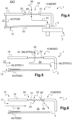
- said dynamic air inlet mouth 15 is oversized to be able to admit more air than necessary for the operation of the engine during an advancement phase of the aircraft 1 when the shutter 45 is in its open position POSO in order to apply the method illustrated on the Figure 3 .
- the actuation device 40 is configured to determine whether the shutter 45 must be placed in its closed position in order to set up a MODF filtered operating mode illustrated on the figure 4 or in its open position to apply a MODO unfiltered operating mode shown on the figures 5 and 6 .
- the various sensors listed above transmit the signals 510, 520, 530, 540, 550 to the controller 47.
- the controller 47 can transmit a control signal in flight to the actuator 46.
- the actuator 46 places the shutter in its closed position POSF during the filtered operating mode MODF.
- air then passes through the filter media 21 according to arrow 90 in a direction of filtration SF going from the external face 22 to the internal face 23. The pollutants are blocked against the external face 22.
- the filtered air flows in the air delivery vein 30 according to arrow 91 to reach the air inlet 3 of motor 2.
- the MODF filtered operating mode is applied as long as pollutants are detected during step STPA2 and possibly as long as the filter media 21 is considered to have a level of clogging lower than the clogging threshold following step STPA4, or even as long as the aircraft 1 flies over a desert area according to an evaluation carried out during the STPA5 step.
- the controller 47 can transmit a control signal to the actuator 46 so that, during a step STPD0, the actuator 46 places the shutter 45 in its open position POSO to reach the unfiltered operating mode MODO .
- the dynamic air inlet mouth 15 then implements a dynamic STPD11 admission step of an air flow 95 under the effect of the advancement of the aircraft 1.
- the inlet mouth d dynamic air 15 circulates this air flow 95 in the internal environment INT according to an air inlet flow rate greater than a minimum flow rate necessary to obtain said required air supply flow rate at the air inlet 3 of the engine 2.
- the air delivery vein 30 implements a STPD12 transfer step of a first part 96 of the air flow 95 towards said motor 2 by suction, the air being sucked in by the motor 2, and transfer of a second part 97 of said air flow 95 towards the filtering media 21. Consequently, this second part 97 of said air flow 95 passes through the filtering media 21 in a direction SN contrary to the usual direction of filtration to reach the external environment EXT.
- the second part 97 of the air flow 95 can tend to remove pollutants from the external face 22 of the filter media 21 and expel them towards the external environment EXT to clean this external face 22.
- the air can enter the air delivery vein 30 for example via the dynamic air inlet mouth 15 and the dynamic air inlet channel 17 according to arrow 99 and via the filter media 21 according to arrow 98.
- an air inlet from the engine of the figure 1 could be axial air inlet and motor air inlet of the figure 2 could conversely be an axial air inlet.
Description
La présente invention concerne un système et un procédé de filtration d'air à média filtrant autonettoyant pour filtrer un comburant d'un moteur d'un aéronef, et par exemple au sein d'un giravion.The present invention relates to an air filtration system and method with self-cleaning filter media for filtering an oxidizer from an engine of an aircraft, and for example within a rotorcraft.
En effet, un aéronef est usuellement muni d'une installation motrice comprenant au moins un moteur à combustion alimenté en air par une entrée d'air. Pour diriger de l'air dans cette entrée d'air, l'aéronef peut comporter un système d'alimentation en air mettant en communication fluidique un milieu extérieur à l'aéronef et l'entrée d'air du moteur.Indeed, an aircraft is usually equipped with a power plant comprising at least one combustion engine supplied with air via an air inlet. To direct air into this air inlet, the aircraft may include an air supply system putting into fluid communication a medium external to the aircraft and the air inlet of the engine.
Un premier type d'alimentation en air est qualifié de dynamique. Un système d'alimentation en air dynamique comporte une bouche d'air dirigée selon le sens d'avancement de l'aéronef pour être alimentée en air extérieur sous l'effet d'une part de la vitesse d'avancement de l'aéronef et du vent et, d'autre part, de l'aspiration d'air réalisée par le moteur en fonctionnement.A first type of air supply is called dynamic. A dynamic air supply system comprises an air vent directed according to the direction of travel of the aircraft to be supplied with external air under the effect of on the one hand the speed of travel of the aircraft and of the wind and, on the other hand, of the air suction produced by the engine in operation.
Un deuxième type d'alimentation en air est qualifié de statique. Un système d'alimentation en air statique est uniquement alimenté en air sous l'effet de l'aspiration d'air réalisée par le moteur en fonctionnement.A second type of air supply is called static. A static air supply system is only supplied with air under the effect of air suction produced by the operating engine.
Ces deux types d'alimentation en air peuvent être combinés au sein d'un même système d'alimentation en air.These two types of air supply can be combined within the same air supply system.
En outre, des « polluants » tels que la poussière, le sable, la neige, le givre sont susceptibles de pénétrer dans un système d'alimentation en air. Ces polluants sont susceptibles de dégrader les performances du moteur par érosion ou colmatage.In addition, "pollutants" such as dust, sand, snow, frost are likely to enter an air supply system. These pollutants are likely to degrade engine performance through erosion or clogging.
Dès lors, un dispositif de filtration d'air peut équiper un système d'alimentation en air pour au moins limiter l'ingestion de polluants.Therefore, an air filtration device can equip an air supply system to at least limit the ingestion of pollutants.
Deux types connus de dispositifs de filtration sont efficaces pour les polluants de petites dimensions, à savoir les dispositifs de type filtre à particules à vortex ou encore de type filtre à barrière.Two known types of filtration devices are effective for small pollutants, namely devices of the vortex particle filter type or even of the barrier filter type.
Un dispositif de filtration de type filtre à barrière est aussi connu sous l'expression anglaise « Inlet barrier Filter ». Un dispositif de filtration de type filtre à barrière comporte un filtre dénommé « média filtrant ». Un tel média filtrant comporte une barrière poreuse. Des passages de petites dimensions traversent la barrière poreuse de part en part selon son épaisseur. Ces passages empêchent des objets présentant des dimensions supérieures aux dimensions des passages de traverser la barrière. Par exemple, un média filtrant peut comprendre une ou plusieurs couches de fibres, telles que des fibres de coton ou des fibres synthétiques, chaque couche étant éventuellement pliée en accordéon pour maximiser sa surface de filtration. L'air passe alors au travers du média filtrant, les polluants qui ne peuvent pas traverser un passage restant bloqués contre une face extérieure du média filtrant. Dès lors, un dispositif de filtration à média filtrant est très efficace. Toutefois, le média filtrant génère de fait des pertes d'installation qui sont fonction de son colmatage.A barrier filter type filtration device is also known by the English expression “Inlet barrier Filter”. A barrier filter type filtration device comprises a filter called “filter media”. Such a filter media includes a porous barrier. Small passages cross the porous barrier from side to side depending on its thickness. These passages prevent objects having dimensions greater than the dimensions of the passages from crossing the barrier. For example, a filter media may comprise one or more layers of fibers, such as cotton fibers or synthetic fibers, each layer optionally being folded in an accordion to maximize its filtration surface area. The air then passes through the filter media, the pollutants which cannot pass through a passage remaining blocked against an exterior face of the filter media. Therefore, a filtration device with filter media is very effective. However, the filter media actually generates installation losses which depend on its clogging.
Diverses techniques permettent d'évaluer le colmatage d'un média filtrant. Par exemple, le document
Lorsque le média filtrant est colmaté, une action de maintenance est entreprise pour le remplacer. Au sein d'un aéronef, le colmatage du média filtrant varie de fait en fonction des conditions environnementales rencontrées et de l'utilisation de l'aéronef. Par exemple, un média filtrant qui filtre l'air en amont d'un moteur d'un hélicoptère tend à être plus rapidement colmaté lorsque l'hélicoptère vole à faibles vitesses dans de l'air chargé en sable. Dès lors, la durée de vie d'un média filtrant est variable en fonction de son utilisation et peut être relativement courte dans des conditions extrêmes.When the filter media is clogged, maintenance action is taken to replace it. Within an aircraft, the clogging of the filter media actually varies depending on the environmental conditions encountered and the use of the aircraft. For example, a filter media that filters the air upstream of a helicopter engine tends to become clogged more quickly when the helicopter flies at low speeds in sand-laden air. Therefore, the lifespan of a filter media varies depending on of its use and can be relatively short in extreme conditions.
L'invention vise à optimiser cette durée de vie.The invention aims to optimize this lifespan.
Le document
De même, le document
Le document
Le document
Le document
Le document
Le document
La présente invention a alors pour objet de proposer un procédé et un système d'alimentation en air à média filtrant, favorablement relativement léger, visant à optimiser la durée de vie du média filtrant.The object of the present invention is therefore to propose a method and an air supply system with filter media, favorably relatively light, aimed at optimizing the lifespan of the filter media.
Ainsi, l'invention vise un procédé pour alimenter en air un moteur, notamment à combustion, d'un aéronef selon un débit d'alimentation en air via un système d'alimentation en air de l'aéronef, ledit système d'alimentation en air comprenant une bouche d'entrée d'air dynamique qui est obturable par un obturateur, ledit obturateur étant mobile entre une position fermée dans laquelle l'obturateur obture ladite bouche d'entrée d'air dynamique et une position ouverte dans laquelle l'obturateur n'obture pas ladite bouche d'entrée d'air dynamique, ledit système d'alimentation en air comprenant une bouche d'entrée d'air statique munie d'un dispositif de filtration, ledit obturateur étant dans la position fermée durant un mode de fonctionnement filtré pendant lequel un air d'un milieu extérieur situé à l'extérieur de l'aéronef est filtré par le dispositif de filtration.Thus, the invention relates to a method for supplying air to an engine, in particular a combustion engine, of an aircraft according to an air supply flow rate via an air supply system of the aircraft, said air supply system air comprising a dynamic air inlet mouth which can be closed by a shutter, said shutter being movable between a closed position in which the shutter closes said dynamic air inlet mouth and an open position in which the shutter does not close said dynamic air inlet mouth, said air supply system comprising a static air inlet mouth provided with a filtration device, said shutter being in the closed position during a mode of filtered operation during which air from an external environment located outside the aircraft is filtered by the filtration device.
Le dispositif de filtration comportant un média filtrant, ce procédé comporte en vol un mode de fonctionnement non filtré qui comprend les étapes suivantes :
- positionnement dudit obturateur dans la position ouverte, pour ne plus obturer la bouche d'entrée d'air dynamique, et
- durant une phase d'avancement de l'aéronef, admission dynamique d'un flux d'air sous l'effet dudit avancement de l'aéronef par la bouche d'entrée d'air dynamique selon un débit d'entrée d'air supérieur à un débit minimum nécessaire pour obtenir ledit débit d'alimentation en air, puis
- transfert d'une première partie dudit flux d'air vers ledit moteur et transfert d'une deuxième partie dudit flux d'air vers le média filtrant, ladite deuxième partie dudit flux d'air traversant le média filtrant pour rejoindre le milieu extérieur à des fins de nettoyage du média filtrant.
- positioning said shutter in the open position, so as to no longer block the dynamic air inlet mouth, and
- during a phase of advancement of the aircraft, dynamic admission of an air flow under the effect of said advancement of the aircraft through the dynamic air inlet mouth according to a higher air inlet flow rate at a minimum flow rate necessary to obtain said air supply flow rate, then
- transfer of a first part of said air flow towards said motor and transfer of a second part of said air flow towards the filtering media, said second part of said air flow passing through the filtering media to reach the external environment at purposes of cleaning the filter media.
L'expression « admission dynamique d'un flux d'air sous l'effet dudit avancement de l'aéronef par la bouche d'entrée d'air dynamique » signifie que le flux d'air pénètre dans le système d'alimentation en air par la bouche d'entrée d'air dynamique au moins sous l'effet de l'avancement de l'aéronef, voire aussi de l'aspiration d'un moteur.The expression "dynamic admission of an air flow under the effect of said advancement of the aircraft through the dynamic air inlet port" means that the air flow enters the air supply system through the ram air inlet mouth at least under the effect of the advancement of the aircraft, or even the suction of an engine.
L'expression « entre une position fermée dans laquelle l'obturateur obture ladite bouche d'entrée d'air dynamique et une position ouverte » signifie que l'obturateur peut être déplacé de la position ouverte à la position fermée et de la position fermée à la position ouverte. Des positions intermédiaires peuvent éventuellement être atteintes, l'obturateur restant agencé dans de telles positions intermédiaires au moins temporairement.The expression "between a closed position in which the shutter blocks said dynamic air inlet mouth and an open position" means that the shutter can be moved from the open position to the closed position and from the closed position to the open position. Intermediate positions may possibly be reached, the shutter remaining arranged in such intermediate positions at least temporarily.
Dans ce contexte, le système d'alimentation en air peut être soit dans un mode de fonctionnement filtré durant lequel l'obturateur est dans la position fermée, soit dans un mode de fonctionnement non filtré durant lequel l'obturateur est dans la position ouverte.In this context, the air supply system can be either in a filtered mode of operation during which the shutter is in the closed position, or in an unfiltered mode of operation during which the shutter is in the open position.
Durant le mode de fonctionnement filtré, l'air situé dans le milieu extérieur traverse le média filtrant selon un sens, dit « sens de filtration » par commodité, allant d'une face externe du média filtrant en contact avec le milieu extérieur vers une face interne du média filtrant. Les polluants éventuels de l'air sont bloqués par le média filtrant au niveau de sa face externe, dans les limites de fonctionnement de ce média filtrant évidemment. L'air nettoyé de polluants éventuels est ensuite canalisé vers le moteur par le système d'alimentation en air. Le média filtrant remplit sa fonction en tendant à éviter l'ingestion de polluants potentiellement gênants par le moteur, tels que par exemple de la poussière, de la terre ou du sable.During the filtered operating mode, the air located in the external environment passes through the filter media in a direction, called "filtration direction" for convenience, going from an external face of the filter media in contact with the external environment towards a face internal of the filter media. Any air pollutants are blocked by the filter media on its external face, obviously within the operating limits of this filter media. The air cleaned of possible pollutants is then channeled to the engine through the air supply system. The filter media fulfills its function by tending to avoid the ingestion of potentially annoying pollutants by the engine, such as for example dust, earth or sand.
Selon l'invention, le procédé comporte de plus un mode de fonctionnement non filtré incluant une phase d'alimentation en air et de nettoyage automatique du média filtrant, le média filtrant étant immobile, qui est mise en oeuvre durant une phase de vol dite « phase d'avancement de l'aéronef ». Une telle phase d'avancement est, par exemple une phase de déplacement de l'aéronef au moins vers l'avant selon un sens allant de la queue vers un nez de l'aéronef. Lorsque cette phase d'alimentation en air et de nettoyage du média filtrant est mise en oeuvre, l'obturateur est placé dans sa position ouverte. En raison de l'avancement de l'aéronef, une veine d'acheminement d'air du système d'alimentation en air est gavée d'air par la bouche d'entrée d'air dynamique. En particulier, la bouche d'entrée d'air dynamique est de manière innovante surdimensionnée pour capter plus d'air que nécessaire pour obtenir le débit d'alimentation en air voulu par le moteur. La bouche d'entrée d'air dynamique peut être dimensionnée de manière usuelle, par calculs et/ou simulations et/ou tests, pour permettre l'obtention d'un débit supérieur à un débit d'alimentation en air prédéterminé spécifié pour le moteur. En raison au moins de la différence de débit entre le débit d'entrée d'air réel et le débit minimum nécessaire pour alimenter le moteur, une première partie du flux d'air est acheminée vers le moteur et aspirée par ce moteur alors qu'une deuxième partie de ce flux d'air est refoulée en dehors du système d'alimentation en air par le seul chemin possible. En particulier, cette deuxième partie du flux d'air admis traverse le média filtrant selon un sens contraire au sens de filtration précédemment décrit. Ainsi, les polluants éventuels captés préalablement par la face externe du média filtrant sont soufflés vers le milieu extérieur. Le niveau de colmatage du média filtrant baisse alors et s'éloigne d'un seuil de colmatage impliquant une action de maintenance.According to the invention, the method further comprises an unfiltered operating mode including an air supply and automatic cleaning phase of the filter media, the filter media being immobile, which is implemented during a so-called “flight phase”. aircraft advancement phase”. Such an advancement phase is, for example a phase of movement of the aircraft at least forwards in a direction going from the tail towards a nose of the aircraft. When this phase of supplying air and cleaning the filter media is implemented, the shutter is placed in its open position. Due to the advancement of the aircraft, an air supply vein of the air supply system is filled with air through the ram air inlet port. In particular, the dynamic air inlet mouth is innovatively oversized to capture more air than necessary to achieve the engine's desired air supply flow rate. The dynamic air inlet port can be dimensioned in the usual manner, by calculations and/or simulations and/or tests, to allow a flow rate greater than a predetermined air supply flow rate specified for the engine to be obtained. . Due at least to the difference in flow rate between the actual air inlet flow rate and the minimum flow rate necessary to power the motor, a first part of the air flow is routed to the motor and sucked in by this motor while a second part of this air flow is pushed out of the air supply system by the only possible route. In particular, this second part of the admitted air flow passes through the filter media in a direction opposite to the direction of filtration previously described. Thus, any pollutants previously captured by the external face of the filter media are blown towards the outside environment. The level of clogging of the filter media then drops and moves away from a clogging threshold requiring maintenance action.
Durant le mode de fonctionnement non filtré, si l'aéronef ne se trouve pas dans ladite phase d'avancement tel que précédemment définie, le moteur peut aspirer de l'air via le média filtrant et/ou la bouche d'entrée d'air dynamique.During the unfiltered operating mode, if the aircraft is not in said advancement phase as previously defined, the engine can suck in air via the filter media and/or the air inlet port. dynamic.
Dès lors, durant la phase d'alimentation en air et de nettoyage du média filtrant ce procédé permet de nettoyer en vol le média filtrant, sans action sur le média filtrant, à savoir au dessus du sol en utilisant une bouche d'entée d'air dynamique surdimensionnée durant l'avancement de l'aéronef.Therefore, during the air supply and cleaning phase of the filter media this process makes it possible to clean the filter media in flight, without action on the filter media, namely above the ground using an inlet mouth of oversized dynamic air during the advancement of the aircraft.
Ce procédé permet donc d'une part de protéger un moteur de polluants dans des phases de vol le nécessitant, du moins tant que le média filtrant n'est pas totalement colmaté, et, d'autre part, de nettoyer le média filtrant en vol si nécessaire et/ou si possible.This process therefore makes it possible, on the one hand, to protect an engine from pollutants in flight phases requiring it, at least as long as the filter media is not completely clogged, and, on the other hand, to clean the filter media in flight. if necessary and/or if possible.
Le procédé peut ainsi permettre, suivant l'utilisation de l'aéronef, d'augmenter la durée de vie du média filtrant et de repousser une action de maintenance.The method can thus make it possible, depending on the use of the aircraft, to increase the lifespan of the filter media and to postpone maintenance action.
Le procédé peut de plus comporter une ou plusieurs des caractéristiques qui suivent, prises seules ou en combinaison.The process may also include one or more of the following characteristics, taken alone or in combination.
Le mode de fonctionnement filtré peut être mis en oeuvre en fonction d'un ou de plusieurs des paramètres suivants.The filtered mode of operation can be implemented based on one or more of the following parameters.
Ainsi, le procédé comporte une étape de détection d'une pollution de l'air dans ledit milieu extérieur, la mise en oeuvre du mode de fonctionnement non filtré, et de fait du mode de fonctionnement filtré, étant fonction au moins de ladite pollution de l'air dans ledit milieu extérieur.Thus, the method comprises a step of detecting air pollution in said external environment, the implementation of the unfiltered operating mode, and therefore of the filtered operating mode, being a function at least of said pollution of the air in said external environment.
L'air peut être considéré non pollué lorsque cet air contient dans un certain volume un nombre de particules inférieur à un seuil de particules.Air can be considered unpolluted when this air contains in a certain volume a number of particles below a particle threshold.
De manière complémentaire ou alternative avec les précédentes possibilités, le procédé peut comporter une étape de détection d'un niveau de colmatage dudit média filtrant, la mise en oeuvre du mode de fonctionnement non filtré, et de fait du mode de fonctionnement filtré, étant fonction au moins dudit niveau de colmatage.Complementary or alternatively with the previous possibilities, the method can include a step of detecting a level of clogging of said filter media, the implementation of the unfiltered operating mode, and therefore of the filtered operating mode, being a function at least of said level of clogging.
De manière complémentaire ou alternative avec les précédentes possibilités, ledit procédé comporte une étape de détection que ledit aéronef évolue selon ladite au moins une phase d'avancement, la mise en oeuvre du mode de fonctionnement non filtré, et de fait du mode de fonctionnement filtré, étant fonction au moins de ladite détection que ledit aéronef évolue selon ladite au moins une phase d'avancement.Complementary or alternatively with the previous possibilities, said method comprises a step of detecting that said aircraft is evolving according to said at least one advancement phase, the implementation of the unfiltered operating mode, and therefore of the filtered operating mode , being a function at least of said detection that said aircraft is evolving according to said at least one advancement phase.
Ladite au moins une phase d'avancement peut comporter une phase de mouvement dudit aéronef selon un sens prédéterminé par rapport à un référentiel dudit aéronef et à une vitesse supérieure à un seuil de vitesse. Par exemple, un tel seuil de vitesse est de l'ordre 100 noeuds soit 185,2 kilomètres par heure.Said at least one advancement phase may include a phase of movement of said aircraft in a predetermined direction relative to a reference frame of said aircraft and at a speed greater than a speed threshold. For example, such a speed threshold is of the order of 100 knots or 185.2 kilometers per hour.
Selon un exemple compatible avec les précédents, ledit procédé peut comporter une étape de détection d'une nature d'un terrain survolé, la mise en oeuvre du mode de fonctionnement non filtré étant fonction au moins de ladite nature. Par exemple, ladite nature est à choisir dans une liste comprenant au moins un des éléments suivants : une zone désertique, une zone peuplée, une ville, une forêt, une étendu d'eau... La nature du terrain survolé peut être évaluée en combinant la position géographique courante de l'aéronef, par exemple sa latitude et sa longitude, à une carte mémorisée contenant ledit terrain et sa nature.According to an example compatible with the preceding ones, said method may include a step of detecting a nature of a terrain flown over, the implementation of the unfiltered operating mode being a function of at least said nature. For example, said nature must be chosen from a list including at least one of the following elements: a desert area, a populated area, a city, a forest, a body of water, etc. The nature of the terrain flown over can be evaluated by combining the current geographical position of the aircraft, for example its latitude and longitude, with a stored map containing said terrain and its nature.
De manière complémentaire ou alternative, le procédé peut comporter une étape de génération d'un signal de commande avec une commande, activée par un pilote, la mise en oeuvre du mode de fonctionnement non filtré étant fonction au moins dudit signal de commande.Complementarily or alternatively, the method may include a step of generating a control signal with a command, activated by a driver, the implementation of the unfiltered operating mode being a function of at least said control signal.
Le système d'alimentation en air peut comprendre une ou plusieurs commandes manuelles, vocales ou visuelles, pour commander l'obturateur et donc pour choisir directement ou indirectement le mode de fonctionnement du système d'alimentation en air.The air supply system may include one or more manual, voice or visual commands to control the shutter and therefore to directly or indirectly choose the mode of operation of the air supply system.
Par exemple, une commande peut être utilisée pour commander un actionneur déplaçant l'obturateur entre sa position fermée et sa position ouverte.For example, a command may be used to control an actuator moving the shutter between its closed position and its open position.
Selon un autre exemple, une commande peut permettre à un pilote de choisir un mode d'opération parmi une liste de modes d'opération, chaque mode d'opération pilotant l'obturateur en fonction d'au moins un des paramètres précédents.According to another example, a command can allow a pilot to choose an operating mode from a list of modes of operation, each mode of operation controlling the shutter according to at least one of the preceding parameters.
Les diverses conditions précédentes peuvent être cumulatives et éventuellement hiérarchisées. Les conditions utilisées et/ou la hiérarchie peuvent varier en fonction éventuellement d'un mode d'opération choisi.The various preceding conditions can be cumulative and possibly hierarchical. The conditions used and/or the hierarchy may vary depending on a chosen mode of operation.
Par exemple, le mode de fonctionnement filtré peut être automatiquement mis en oeuvre en plaçant l'obturateur dans sa position fermée si une pollution est détectée, voire aussi si le média filtrant présente un niveau de colmatage inférieur à un seuil de colmatage.For example, the filtered operating mode can be automatically implemented by placing the shutter in its closed position if pollution is detected, or even if the filter media has a level of clogging less than a clogging threshold.
Selon un exemple, le choix du mode de fonctionnement filtré ou non filtré peut uniquement être réalisé par un pilote à l'aide d'une commande prévue à cet effet. Le pilote peut alors choisir la position de l'obturateur en fonction des conditions de vol et/ou de la mission à réaliser, et/ou de l'environnement et/ou de son choix d'optimiser ou non la durée de vie du média filtrant.According to one example, the choice of filtered or unfiltered operating mode can only be made by a pilot using a command provided for this purpose. The pilot can then choose the position of the shutter depending on the flight conditions and/or the mission to be carried out, and/or the environment and/or his choice of optimizing or not the lifespan of the media. filtering.
Selon un exemple, le mode de fonctionnement non filtré est automatiquement mis en oeuvre en positionnant l'obturateur dans sa position ouverte seulement si ledit aéronef évolue selon ladite au moins une phase d'avancement et/ou si le niveau de colmatage du média filtrant est supérieur ou égal à un seuil de colmatage.According to one example, the unfiltered operating mode is automatically implemented by positioning the shutter in its open position only if said aircraft is evolving according to said at least one advancement phase and/or if the level of clogging of the filter media is greater than or equal to a clogging threshold.
Il est aussi possible de prévoir divers modes d'opération pouvant être choisis par un pilote avec une commande appropriée.It is also possible to provide various modes of operation that can be chosen by a pilot with appropriate control.
Par exemple, selon un mode d'opération économique, l'obturateur est par défaut placé dans sa position fermée et placé dans sa position ouverte seulement tant qu'aucune pollution n'est détectée et que la vitesse d'avancement est supérieure au seuil de vitesse.For example, according to an economical mode of operation, the shutter is by default placed in its closed position and placed in its open position only as long as no pollution is detected and the forward speed is greater than the threshold of speed.
Selon un mode d'opération de protection optimale, l'obturateur est par défaut placé dans sa position ouverte puis placé dans sa position fermée jusqu'à la fin du vol si une pollution est détectée et si en même temps le terrain survolé est une zone désertique.According to an optimal protection operating mode, the shutter is by default placed in its open position then placed in its closed position until the end of the flight if pollution is detected and if at the same time the terrain flown over is an area desert.
Selon un mode d'opération privilégiant la performance, l'obturateur est par défaut placé dans sa position fermée puis placé dans sa position ouverte tant qu'aucune pollution n'est détectée et que le terrain survolé est une ville.According to an operating mode favoring performance, the shutter is by default placed in its closed position then placed in its open position as long as no pollution is detected and the terrain flown over is a city.
Dans tous les cas, le mode de fonctionnement non filtré peut être automatiquement mis en oeuvre en positionnant l'obturateur dans sa position ouverte si le niveau de colmatage du média filtrant est supérieur ou égal à un seuil de colmatage.In all cases, the unfiltered operating mode can be automatically implemented by positioning the shutter in its open position if the level of clogging of the filter media is greater than or equal to a clogging threshold.
Ces divers modes d'opération sont donnés à titre d'exemples pour indiquer que les diverses variantes précitées sont compatibles entre elles.These various modes of operation are given as examples to indicate that the various aforementioned variants are compatible with each other.
Outre un procédé, l'invention vise un système selon la revendication 7 apte à appliquer ce procédé, voire configuré pour appliquer ce procédé.In addition to a method, the invention relates to a system according to claim 7 capable of applying this method, or even configured to apply this method.
Ce système d'alimentation en air est configuré pour alimenter en air un moteur d'un aéronef selon un débit d'alimentation en air, ledit système d'alimentation en air comprenant une bouche d'entrée d'air dynamique qui est obturable par un obturateur mobile, ledit obturateur étant mobile entre une position fermée dans laquelle l'obturateur obture ladite bouche d'entrée d'air dynamique et une position ouverte dans laquelle l'obturateur n'obture pas ladite bouche d'entrée d'air dynamique, ledit système d'alimentation en air comprenant une bouche d'entrée d'air statique munie d'un dispositif de filtration.This air supply system is configured to supply air to an engine of an aircraft according to an air supply flow rate, said air supply system comprising a dynamic air inlet port which is closable by a movable shutter, said shutter being movable between a closed position in which the shutter closes said dynamic air inlet mouth and an open position in which the shutter does not close said dynamic air inlet mouth, said air supply system comprising a static air inlet port provided with a filtration device.
De plus, le dispositif de filtration comporte un média filtrant qui débouche sur une veine d'acheminement d'air dudit système d'alimentation en air. Cette veine d'acheminement d'air débouche directement ou via un ou plusieurs conduits sur le moteur à alimenter en air. Ladite bouche d'entrée d'air dynamique est fluidiquement reliée à la veine d'acheminement d'air en amont du média filtrant selon un sens allant de la bouche d'entrée d'air dynamique vers le moteur à alimenter. Ladite bouche d'entrée d'air dynamique est surdimensionnée pour ingérer dynamiquement un flux d'air durant une phase d'avancement dudit aéronef dans un mode de fonctionnement non filtré, selon un débit d'entrée d'air supérieur à un débit minimum nécessaire pour obtenir ledit débit d'alimentation en air, pour qu'une première partie dudit flux d'air soit acheminé vers ledit moteur et qu'une deuxième partie dudit flux d'air sorte de ladite veine d'acheminement d'air par ledit média filtrant à des fins de nettoyage.In addition, the filtration device comprises a filter media which opens into an air delivery vein of said system air supply. This air delivery vein opens directly or via one or more conduits onto the engine to be supplied with air. Said dynamic air inlet mouth is fluidly connected to the air delivery vein upstream of the filtering media in a direction going from the dynamic air inlet mouth towards the engine to be powered. Said dynamic air inlet mouth is oversized to dynamically ingest a flow of air during an advancement phase of said aircraft in an unfiltered operating mode, according to an air inlet flow rate greater than a minimum flow rate necessary. to obtain said air supply flow rate, so that a first part of said air flow is routed to said motor and a second part of said air flow leaves said air delivery vein by said media filter for cleaning purposes.
Par suite, le média filtrant et la bouche d'entrée d'air dynamique aboutissent tous deux sur la veine d'acheminement d'air, cette veine d'acheminement d'air ayant une sortie configurée pour alimenter en air le moteur.Subsequently, the filter media and the dynamic air inlet mouth both end on the air delivery vein, this air delivery vein having an outlet configured to supply air to the engine.
L'expression « Ladite bouche d'entrée d'air dynamique est fluidiquement reliée à la veine d'acheminement d'air en amont du média filtrant selon un sens allant de la bouche d'entrée d'air dynamique vers le moteur à alimenter » signifie que le média filtrant abouti dans la veine d'acheminement d'air entre ladite sortie de la veine d'acheminement d'air et la bouche d'entrée d'air dynamique. Par exemple, le média filtrant comporte une face interne qui délimite localement la veine d'acheminement d'air entre ladite sortie de la veine d'acheminement d'air et la bouche d'entrée d'air dynamique.The expression “Said dynamic air inlet mouth is fluidly connected to the air delivery vein upstream of the filtering media in a direction going from the dynamic air inlet mouth towards the engine to be supplied” means that the filter media ends in the air delivery vein between said outlet of the air delivery vein and the dynamic air inlet mouth. For example, the filter media has an internal face which locally delimits the air delivery vein between said outlet of the air delivery vein and the dynamic air inlet mouth.
Par exemple, le média filtrant est immobile dans un référentiel du système d'alimentation en air, notamment par rapport aux autres organes du système et par exemple à la veine d'acheminement d'air, contrairement à un dispositif rotatif.For example, the filter media is stationary in a reference frame of the air supply system, particularly in relation to the other organs of the system and for example to the air delivery vein, unlike a rotating device.
Le système peut comprendre une ou plusieurs des caractéristiques qui suivent, prises seules ou en combinaison.The system may include one or more of the following features, taken alone or in combination.
Ainsi, le système d'alimentation en air peut comporter un dispositif d'actionnement muni d'un actionneur coopérant avec ledit obturateur, ledit actionneur étant configuré pour déplacer ledit obturateur entre la position ouverte et la position fermée.Thus, the air supply system may comprise an actuating device provided with an actuator cooperating with said shutter, said actuator being configured to move said shutter between the open position and the closed position.
Le dispositif d'actionnement peut comprendre un contrôleur indépendant ou non de l'actionneur, et dédié ou non à cette application, pour commander l'actionneur en appliquant le procédé de l'invention en fonction d'un ou de plusieurs signaux reçus, analogiques ou numériques.The actuation device may comprise a controller independent or not of the actuator, and dedicated or not to this application, to control the actuator by applying the method of the invention as a function of one or more received analog signals. or digital.
Par exemple, le système d'alimentation en air peut comporter au moins une commande pouvant être activée par un pilote, ladite au moins une commande étant reliée par une liaison filaire ou non filaire au dispositif d'actionnement.For example, the air supply system may include at least one control that can be activated by a pilot, said at least one control being connected by a wired or non-wired connection to the actuation device.
Par exemple, le système d'alimentation en air peut comporter que le au moins un senseur de pollution est relié par une liaison filaire ou non filaire au dispositif d'actionnement, ledit senseur de pollution étant configuré pour émettre un signal de pollution porteur d'une information indiquant si l'air présent dans le milieu extérieur est pollué.For example, the air supply system may include that the at least one pollution sensor is connected by a wired or non-wired connection to the actuation device, said pollution sensor being configured to emit a pollution signal carrying information indicating whether the air present in the external environment is polluted.
Par exemple, un tel senseur de pollution peut comprendre un senseur de particules usuel, un capteur de givre... Le senseur de particules peut être agencé à l'extérieur de la veine d'acheminement d'air, à proximité ou non de la bouche d'entrée d'air dynamique ou du média filtrant.For example, such a pollution sensor can include a usual particle sensor, a frost sensor, etc. The particle sensor can be arranged outside the air delivery channel, close or not to the dynamic air inlet mouth or filter media.
Par exemple, le système d'alimentation en air peut comporter un senseur d'avancement configuré pour émettre un signal d'avancement transmis par une liaison filaire ou non filaire au dispositif d'actionnement, le signal d'avancement étant porteur d'une information indiquant que ledit aéronef évolue selon ladite au moins une phase d'avancement.For example, the air supply system may include a progress sensor configured to emit a progress signal transmitted by a wired or non-wired connection to the actuation device, the progress signal carrying information indicating that said aircraft is evolving according to said at least one advancement phase.
Un tel senseur d'avancement peut comporter un capteur de vitesse usuel, par exemple un capteur d'un système de positionnement par satellites, une sonde à tube de Pitot...Such a progress sensor may include a usual speed sensor, for example a sensor from a satellite positioning system, a Pitot tube probe, etc.
Par exemple, le système d'alimentation en air comporte un senseur de colmatage configuré pour émettre un signal de colmatage transmis par une liaison filaire ou non filaire au dispositif d'actionnement, le signal de colmatage étant porteur d'une information indiquant que ledit média filtrant présente un niveau de colmatage supérieur ou égal à un seuil de colmatage.For example, the air supply system comprises a clogging sensor configured to emit a clogging signal transmitted by a wired or non-wired connection to the actuation device, the clogging signal carrying information indicating that said media filter has a level of clogging greater than or equal to a clogging threshold.
Un tel senseur peut être d'un type connu. Par exemple, un tel senseur comporte un capteur de pression mesurant une pression en amont du média filtrant et un capteur de pression mesurant une pression de l'air en aval du média filtrant, un calculateur du senseur ou le contrôleur compilant les mesures pour déterminer le niveau de colmatage du média filtrant.Such a sensor may be of a known type. For example, such a sensor comprises a pressure sensor measuring a pressure upstream of the filter media and a pressure sensor measuring an air pressure downstream of the filter media, a sensor calculator or the controller compiling the measurements to determine the level of clogging of the filter media.
Selon un exemple compatible avec les précédents, ledit système d'alimentation en air peut comporter un senseur de positionnement configuré pour émettre un signal de positionnement transmis par une liaison filaire ou non filaire au dispositif d'actionnement, le signal de positionnement étant porteur d'une information indiquant la position géographique de l'aéronef.According to an example compatible with the preceding ones, said air supply system may comprise a positioning sensor configured to emit a positioning signal transmitted by a wired or non-wired connection to the actuation device, the positioning signal being a carrier of information indicating the geographical position of the aircraft.
Par ailleurs, l'invention vise aussi un aéronef muni d'au moins un moteur, cet aéronef comportant un système d'alimentation en air selon l'invention pour acheminer un air présent dans un milieu extérieur situé à l'extérieur dudit aéronef vers ledit moteur.Furthermore, the invention also relates to an aircraft equipped with at least one engine, this aircraft comprising an air supply system according to the invention to convey air present in an external environment located outside of said aircraft to said engine.
L'invention et ses avantages apparaîtront avec plus de détails dans le cadre de la description qui suit avec des exemples donnés à titre illustratif en référence aux figures annexées qui représentent :
- la
figure 1 , un schéma présentant un système d'alimentation en air ayant un obturateur à ogive, - la
figure 2 , un schéma présentant un système d'alimentation en air ayant un obturateur à volet, - la
figure 3 , un schéma illustrant le procédé de l'invention, - la
figure 4 , un schéma présentant un système d'alimentation en air dans le mode de fonctionnement filtré, - la
figure 5 , un schéma présentant un système d'alimentation en air dans le mode de fonctionnement non filtré et durant une phase d'avancement, et - la
figure 6 , un schéma présentant un système d'alimentation en air dans le mode de fonctionnement non filtré et en dehors d'une phase d'avancement.
- there
figure 1 , a diagram showing an air supply system having a bullet shutter, - there
figure 2 , a diagram showing an air supply system having a shutter, - there
Figure 3 , a diagram illustrating the process of the invention, - there
figure 4 , a diagram showing an air supply system in the filtered operating mode, - there
figure 5 , a diagram showing an air supply system in the unfiltered operating mode and during an advancement phase, and - there
Figure 6 , a diagram showing an air supply system in the unfiltered operating mode and outside of an advancement phase.
Les éléments présents dans plusieurs figures distinctes sont affectés d'une seule et même référence.Elements present in several distinct figures are assigned a single and same reference.
La
Le système d'alimentation en air 10 est configuré pour alimenter une entrée d'air 3 du moteur 2 selon un débit d'alimentation en air. Une telle entrée d'air 3 peut être une entrée d'air axiale selon l'exemple illustré sur la
A cet effet, le système d'alimentation en air 10 comporte, dans un milieu interne INT, une veine d'acheminement d'air 30. La veine d'acheminement d'air 30 présente une sortie, à savoir un tronçon de sortie, qui débouche sur l'entrée d'air 3 du moteur 2. La veine d'acheminement d'air 30 est délimitée par une enveloppe externe, par exemple sensiblement étanche à l'air. Cette enveloppe externe peut comporter au moins une paroi, au moins un capot...For this purpose, the
Pour capter de l'air à partir d'un milieu extérieur EXT et l'acheminer dans le moteur 2 via la veine d'acheminement d'air 30, le système d'alimentation en air 10 comprend une bouche d'entrée d'air statique 25. Cette bouche d'entrée d'air statique 25 comprend un passage ménagé dans l'enveloppe externe et mettant en communication fluidique le milieu extérieur EXT et la veine d'acheminement d'air 30. En outre, la bouche d'entrée d'air statique 25 est munie d'un dispositif de filtration 20. Ce dispositif de filtration 20 comporte un média filtrant 21, qui couvre par exemple l'intégralité dudit passage. Le média filtrant 21 débouche sur la veine d'acheminement d'air 30, en amont du moteur 2. On rappelle qu'un média filtrant 21 comporte une barrière poreuse, comportant par exemple une ou plusieurs couches de tissus, de mousse, de mat ou autres. Le média filtrant 21 comporte une face externe 22 au regard du milieu externe EXT et une face interne 23 délimitant localement la veine d'acheminement d'air 30, des orifices mettant en communication fluidique la face externe 22 et la face interne 23.To capture air from an external environment EXT and route it into the
Par ailleurs, le système d'alimentation en air 10 comprend une bouche d'entrée d'air dynamique 15 qui débouche aussi sur la veine d'acheminement d'air. Cette bouche d'entrée d'air est qualifiée de dynamique dans la mesure où l'air peut être capté sous l'effet de l'avancement de l'aéronef 1. La bouche d'entrée d'air dynamique 15 peut comporter un carter 16 de l'enveloppe externe délimitant un canal d'entrée d'air dynamique 17. Par exemple, le carter 16 a la forme d'un divergent annulaire. La bouche d'entrée d'air dynamique 15 et en particulier son canal d'entrée d'air dynamique 17 peuvent être dirigés selon un axe dynamique AX1 sensiblement parallèle à un axe AX0 de l'aéronef 1 allant de sa queue AR vers son nez AV. Une grille peut aussi protéger le canal d'entrée d'air dynamique 17.Furthermore, the
Par ailleurs, la bouche d'entrée d'air dynamique 15 débouche fluidiquement sur la veine d'acheminement d'air 30, en amont du média filtrant 21 selon un sens 85 allant de la bouche d'entrée d'air dynamique 15 vers le moteur 2. Ainsi, l'air pénétrant dans la bouche d'entrée d'air dynamique 15 traverse le canal d'entrée d'air dynamique 17 et rejoint la veine d'acheminement d'air 30 pour atteindre le moteur 2 et le média filtrant 21.Furthermore, the dynamic
La bouche d'entrée d'air dynamique 15, et en particulier son canal d'entrée d'air dynamique 17, peuvent être obturés par un obturateur 45 mobile. Cet obturateur 45 est mobile, en translation et/ou en rotation, entre une position fermée POSF illustrée avec des pointillés sur la
Cet obturateur 45 comporte selon l'exemple de la
Cependant, tout autre moyen équivalent peut être utilisé. A titre illustratif, la
Dès lors, le système d'alimentation en air 10 comporte un dispositif d'actionnement 40 pour mettre en mouvement sur requête l'obturateur 45. Ainsi, le dispositif d'actionnement 40 est muni d'un actionneur 46 coopérant avec l'obturateur 45 pour le déplacer entre la position ouverte POSO et la position fermée POSF. Un tel actionneur 46 peut prendre la forme d'un actionneur électrique, pneumatique, hydraulique... Selon l'exemple de la
Par ailleurs, le dispositif d'actionnement 40 peut comprendre un contrôleur 47 relié par une liaison filaire ou non filaire à l'actionneur 46 pour ordonner le déplacement de l'obturateur 45 en fonction d'un ou plusieurs signaux, analogiques ou numériques.Furthermore, the
L'obturateur 45 et éventuellement son actionneur 46 peuvent être agencés dans le milieu interne INT du système d'alimentation en air, selon les illustrations en traits pleins. Par exemple, un actionneur 46 porte l'obturateur 45 associé. Des ailettes ou autres fixent cet ensemble à l'enveloppe extérieure.The
Alternativement, selon l'illustration en traits pointillés, un contrôleur 47 peut être déporté en dehors du milieu interne INT.Alternatively, according to the illustration in dotted lines, a
Indépendamment de la réalisation, un contrôleur 47 peut comprendre par exemple au moins un processeur et au moins une mémoire, au moins un circuit intégré, au moins un système programmable, au moins un circuit logique, ces exemples ne limitant pas la portée donnée à l'expression « contrôleur ». Le contrôleur 47 peut ainsi comprendre un ou plusieurs calculateurs. Le terme « contrôleur » désigne une unité pouvant piloter chaque actionneur 46 en fonction de données d'entrées et d'une logique interne. Le terme processeur peut désigner aussi bien une unité centrale de traitement connue sous l'acronyme CPU, une unité graphique de traitement GPU, une unité digitale connue sous l'acronyme DSP, un microcontrôleur...Independently of the embodiment, a
Pour déterminer la position dans laquelle doit se trouver l'obturateur 45, le système d'alimentation en air 10 peut comprendre un ou plusieurs des senseurs qui suivent. Le terme « senseur » est à interpréter au sens large, un senseur pouvant comprendre au moins un capteur émettant un signal de mesure analogique ou numérique voire éventuellement une unité de calcul apte à émettre à son tour un signal en fonction du signal de mesure reçu et d'une logique interne.To determine the position in which the
Ainsi, le système d'alimentation en air 10 peut comporter au moins une commande 51 reliée par une liaison filaire ou non filaire au dispositif d'actionnement 40. La ou les commandes peuvent être activées par un pilote, manuellement ou par une instruction vocale ou encore par un mouvement, pour transmettre un signal de commande 510 au contrôleur 47. Une commande 51 peut prendre la forme d'un commutateur à au moins deux positions, d'une face tactile permettant de choisir une possibilité parmi plusieurs possibilités et par exemple parmi plusieurs modes d'opération....Thus, the
Le système d'alimentation en air 10 peut comporter au moins un senseur de pollution 52 relié par une liaison filaire ou non filaire au dispositif d'actionnement 40. Le ou les senseurs de pollution 52 sont configurés pour émettre un signal de pollution 520, transmis au contrôleur 47, porteur d'une information indiquant si l'air présent dans le milieu extérieur EXT est pollué. Par exemple, un senseur de pollution 52 peut comprendre un capteur de givre usuel et/ou un senseur de pollution 52 peut capter des particules de sables ou de poussières pour évaluer le nombre de particules dans l'air... Le contrôleur 47 peut recevoir ce nombre de particules et le comparer à un seuil de particules pour déterminer que l'air n'est pas pollué lorsque le nombre mesuré de particules est inférieur au seuil de particules. Selon une autre méthode, le senseur de pollution 52 comporte une unité effectuant cette comparaison et transmettant un signal de pollution indiquant si l'air est pollué ou non.The
Le système d'alimentation en air 10 peut comporter un senseur d'avancement 53 configuré pour émettre un signal d'avancement 530 numérique ou analogique transmis par une liaison filaire ou non filaire au contrôleur 47. Le signal d'avancement 530 étant porteur d'une information indiquant que ledit aéronef 1 évolue ou non selon une phase de vol dite « une phase d'avancement ». Par exemple, un senseur d'avancement 53 peut comprendre un capteur de vitesse pour évaluer la vitesse air de l'aéronef ou un autre type de vitesse. Le contrôleur 47 peut recevoir cette vitesse et la comparer à un seuil de vitesse pour déterminer que l'aéronef 1 effectue une dite phase d'avancement lorsque la vitesse mesurée est supérieure à un seuil de vitesse. Selon une autre méthode, le senseur d'avancement 53 comporte une unité effectuant cette comparaison et transmettant un signal d'avancement 530 indiquant si l'aéronef 1 effectue une dite phase d'avancement ou non.The
Le système d'alimentation en air 10 peut comporter un senseur de colmatage 54 émettant un signal de colmatage 540, analogique ou numérique, transmis par une liaison filaire ou non filaire au contrôleur 47, le signal de colmatage 540 étant porteur d'une information indiquant que ledit média filtrant 21 présente ou non un niveau de colmatage supérieur ou égal à un seuil de colmatage. Par exemple, un senseur de colmatage 54 peut comprendre un ou plusieurs capteurs de pression. Le contrôleur 47 peut recevoir un ou des signaux de mesure, peut les décoder pour en déduire un niveau de colmatage comparé à un seuil de colmatage afin de déterminer si le média filtrant 21 doit être nettoyé. Selon une autre méthode, le senseur de colmatage 54 comporte une unité effectuant cette comparaison et transmettant un signal de colmatage 540 indiquant si le média filtrant 21 doit être nettoyé.The
Le système d'alimentation en air 10 peut comporter un senseur de positionnement 55 configuré pour émettre un signal de positionnement 550 transmis par une liaison filaire ou non filaire au dispositif d'actionnement 40, le signal de positionnement 550 étant porteur d'une information indiquant la position géographique de l'aéronef 1. De la même manière que précédemment, le contrôleur 47 peut traiter le signal de positionnement 550 pour déterminer ladite position géographique ou peut recevoir cette position géographique. Le contrôleur 47 ou le senseur de positionnement 55 peut appliquer des instructions pour en déduire la nature du terrain survolé à l'aide d'une modélisation de ce terrain.The
Par ailleurs, ladite bouche d'entrée d'air dynamique 15 est surdimensionnée pour pouvoir admettre plus d'air que nécessaire pour le fonctionnement du moteur durant une phase d'avancement de l'aéronef 1 lorsque l'obturateur 45 est dans sa position ouverte POSO afin d'appliquer le procédé illustré sur la
En référence à la
A cet effet, durant des étapes optionnelles STPA1, STPA2, STPA3, STPA4, STPA5, le ou les divers senseurs énumérés précédemment transmettent les signaux 510, 520, 530, 540, 550 au contrôleur 47.To this end, during optional steps STPA1, STPA2, STPA3, STPA4, STPA5, the various sensors listed above transmit the
Ainsi, la mise en oeuvre du mode de fonctionnement non filtré MODO peut être fonction :
- au moins de la pollution de l'air dans le milieu extérieur EXT évaluée lors d'une étape de détection STPA2 d'une pollution de l'air mise en oeuvre avec le senseur de
pollution 52, et/ou - au moins d'un signal de commande 510 émis par une commande lors d'une étape de génération STPA1 d'un signal de commande 510 avec une commande 51, activée par un pilote, et/ou
- au moins d'un niveau de colmatage dudit média filtrant 21 évalué lors d'une étape de détection STPA4 d'un niveau de colmatage mise en oeuvre par un senseur de colmatage 54, et/ou
- au moins de la détection que ledit aéronef 1 évolue selon une phase d'avancement évaluée lors d'une étape de détection STPA3 mis en oeuvre avec le senseur d'avancement 53, et/ou
- au moins de la nature du terrain survolé évaluée lors d'une étape de détection STPA5 d'une nature d'un terrain survolé mise en oeuvre avec le senseur de
position 55 pour déterminer la position de l'aéronef 1 et reporter cette position dans une carte présentant la nature du terrain.
- at least air pollution in the external environment EXT evaluated during a STPA2 detection step of air pollution implemented with the
pollution sensor 52, and/or - at least one
control signal 510 emitted by a command during a STPA1 generation step of acontrol signal 510 with acommand 51, activated by a pilot, and/or - at least one level of clogging of said
filter media 21 evaluated during a STPA4 detection step of a level of clogging implemented by a cloggingsensor 54, and/or - at least the detection that said
aircraft 1 is evolving according to an advancement phase evaluated during a STPA3 detection step implemented with theadvancement sensor 53, and/or - at least the nature of the terrain flown over evaluated during a STPA5 detection step of a nature of terrain flown over implemented works with the
position sensor 55 to determine the position of theaircraft 1 and report this position in a map presenting the nature of the terrain.
Ainsi, en fonction du cas courant, le contrôleur 47 peut transmettre en vol un signal de commande à l'actionneur 46. Durant une étape STPC, l'actionneur 46 place alors l'obturateur dans sa position fermée POSF durant le mode de fonctionnement filtré MODF. En référence à la
Selon divers exemples, le mode de fonctionnement filtré MODF est appliqué tant que des polluants sont détectés lors de l'étape STPA2 et éventuellement tant que le média filtrant 21 est considéré comme présentant un niveau de colmatage inférieur au seuil de colmatage suite à l'étape STPA4, voire tant que l'aéronef 1 survole une zone désertique selon une évaluation réalisée lors de l'étape STPA5.According to various examples, the MODF filtered operating mode is applied as long as pollutants are detected during step STPA2 and possibly as long as the
A l'inverse, le contrôleur 47 peut transmettre un signal de commande à l'actionneur 46 afin que, durant une étape STPD0, l'actionneur 46 place l'obturateur 45 dans sa position ouverte POSO pour atteindre le mode de fonctionnement non filtré MODO.Conversely, the
Durant une phase d'avancement de l'aéronef 1 et en référence à la
En raison de ce gavage d'air, la veine d'acheminement d'air 30 met en oeuvre une étape de transfert STPD12 d'une première partie 96 du flux d'air 95 vers ledit moteur 2 par aspiration, l'air étant aspiré par le moteur 2, et de transfert d'une deuxième partie 97 dudit flux d'air 95 vers le média filtrant 21. Par conséquent, cette deuxième partie 97 dudit flux d'air 95 traverse le média filtrant 21 selon un sens SN contraire au sens de filtration usuel pour rejoindre le milieu extérieur EXT. La deuxième partie 97 du flux d'air 95 peut tendre à décoller des polluants de la face externe 22 du média filtrant 21 et les expulser vers le milieu externe EXT pour nettoyer cette face externe 22.Due to this air feeding, the
En dehors de cette phase d'avancement et en référence à la
Par exemple, une entrée d'air du moteur de la
Claims (14)
- Method for supplying air to an engine (2) of an aircraft (1) at an air supply flow rate via an air supply system (10) of the aircraft (1), said air supply system (10) comprising a dynamic air intake vent (15) that can be closed by a movable closure member (45), said movable closure member (45) being movable between a closed position (POSF) in which the closure member (45) closes said dynamic air intake vent (15) and an open position (POSO) in which the closure member (45) does not close said dynamic air intake vent (15), said air supply system (10) comprising a static air intake vent (25) equipped with a filtration device (20), said closure member (45) being in the closed position during a filtered operating mode (MODF) during which air from an external environment situated outside the aircraft (1) is filtered by the filtration device (20),
characterized in that the filtration device has a filter medium (21), said method comprises, during flight, an unfiltered operating mode (MODO), said method comprising a step of detecting (STPA2) air pollution in said external environment (EXT), the implementation of the unfiltered operating mode (MODO) being a function at least on said air pollution in said external environment (EXT), the unfiltered operating mode (MODO) comprising the following steps:- positioning (STPD0) of said closure member (45) in the open position (POSO), and- during a phase of forward travel of the aircraft, dynamic intake (STPD11) of an air flow (95) as a result of said forward travel of the aircraft (1) via the dynamic air intake vent (15) at an air intake flow rate higher than a minimum flow rate necessary in order to obtain the air supply flow rate, then transfer (STPD12) of a first portion (96) of said air flow (95) to said engine (2) and a second portion (97) of said air flow (95) to the filter medium (21), said second portion (97) of said flow of air (95) passing through the filter medium (21) to return to the external environment (EXT) in order to clean the filter medium (21). - Method according to Claim 1,
characterized in that the method comprises a step of generating (STPA1) a control signal (510) with a control (51), activated by a pilot, the implementation of the unfiltered operating mode (MODO) being a function at least of said control signal (510). - Method according to any one of Claims 1 to 2,
characterized in that said method comprises a step of detecting (STPA4) a clogging level of said filter medium (21), the implementation of the unfiltered operating mode (MODO) being a function at least of said clogging level. - Method according to any one of Claims 1 to 3,
characterized in that said method comprises a step of detecting (STPA3) that said aircraft (1) is progressing according to said at least one phase of forward travel, the implementation of the unfiltered operating mode (MODO) being a function at least of said detection that said aircraft (1) is progressing according to said at least one phase of forward travel. - Method according to any one of Claims 1 to 4,
characterized in that said at least one phase of forward travel includes a phase of movement of said aircraft (1) in a predetermined direction relative to an reference frame of said aircraft (1) and at a speed greater than a speed threshold. - Method according to any one of Claims 1 to 5,
characterized in that said method comprises a step of detecting (STPA5) the nature of a terrain being flown over, the implementation of the unfiltered operating mode (MODO) being a function at least of said nature. - Air supply system (10) configured to supply air to an aircraft (1) engine (2) according to an air supply rate and capable of implementing the method according to any one of Claims 1 to 6, said air supply system comprising a dynamic air intake vent (15) that can be closed by a movable closure member (45), said closure member (45) being movable between a closed position in which the closure member (45) closes said dynamic air intake vent (15) and an open position (POSO) in which the closure member (45) does not close said dynamic air intake vent(15), said air supply system (10) comprising a static air intake vent (25) provided with a filtration device (20), characterized in that said filtration device (20) comprises a filter medium (21) which opens into an air delivery duct (30) of said air supply system (10); said air supply system comprises at least one air pollution sensor (52) in the external environment; said dynamic air intake vent (15) being fluidly connected to the air delivery duct (30) upstream of the filter medium (21) in a direction (85) going from the dynamic air intake vent (15) towards the engine (2) to be supplied; said dynamic air intake vent (15) being oversized in order to dynamically ingest an air flow (95) during a phase of forward travel of said aircraft (1) in a non-filtered operating mode, at an air intake rate greater than a minimum rate necessary to obtain said air supply rate, so that a first portion (96) of said air flow (95) is delivered to said engine (2) and a second portion (97) of said air flow (95) exits from said air delivery duct (30) through said filter medium (21) for cleaning purposes.
- System according to Claim 7,
characterized in that said air supply system (10) comprises an actuation device (40) equipped with an actuator (46) cooperating with said closure member (45), said actuator (46) being configured to move said closure member (45) between the open position (POSO) and the closed position (POSF). - System according to Claim 8,
characterized in that said air supply system (10) comprises at least one control (51) that can be activated by a pilot, said at least one control (51) being connected by a wired or wireless connection to the actuation device (40). - System according to any one of Claims 7 to 9,
characterized in that said pollution sensor (52) is connected by a wired or wireless link to the actuation device (40), said pollution sensor (52) being configured to emit a pollution signal (520) carrying information indicating whether the air in the external environment (EXT) is polluted. - System according to any one of Claims 7 to 10,
characterized in that said air supply system (10) comprises a forward travel sensor (53) configured to emit a forward travel signal (530) transmitted by a wired or wireless link to the actuation device (40), the forward travel signal (530) carrying information indicating that said aircraft (1) is advancing in said at least one phase of forward travel. - System according to any one of Claims 7 to 11,
characterized in that said air supply system (10) comprises a clogging sensor (54) configured to emit a clogging signal (540) transmitted by a wired or wireless link to the actuation device (40), the clogging signal (540) carrying information indicating that said filter medium (21) has a clogging level greater than or equal to a clogging threshold. - System according to any one of Claims 7 to 11,
characterized in that said air supply system (10) comprises a positioning sensor (55) configured to emit a positioning signal (550) transmitted by a wired or wireless link to the actuation device (40), the positioning signal (550) carrying information indicating the geographical position of the aircraft. - Aircraft (1) equipped with at least one engine (2),
characterized in that said aircraft (1) comprises an air supply system (10) according to any one of Claims 7 to 13 for conveying air from an external environment located outside said aircraft (1) to said engine (2).
Applications Claiming Priority (1)
| Application Number | Priority Date | Filing Date | Title |
|---|---|---|---|
| FR2006839A FR3111947B1 (en) | 2020-06-30 | 2020-06-30 | self-cleaning media air filtration system and method for an aircraft engine |
Publications (2)
| Publication Number | Publication Date |
|---|---|
| EP3933182A1 EP3933182A1 (en) | 2022-01-05 |
| EP3933182B1 true EP3933182B1 (en) | 2024-02-28 |
Family
ID=72885689
Family Applications (1)
| Application Number | Title | Priority Date | Filing Date |
|---|---|---|---|
| EP21170514.0A Active EP3933182B1 (en) | 2020-06-30 | 2021-04-26 | System and method for filtering air with a self-cleaning filtering medium for an engine of an aircraft |
Country Status (6)
| Country | Link |
|---|---|
| US (2) | US11661205B2 (en) |
| EP (1) | EP3933182B1 (en) |
| KR (1) | KR102524144B1 (en) |
| CN (1) | CN113944551A (en) |
| CA (1) | CA3116233A1 (en) |
| FR (1) | FR3111947B1 (en) |
Citations (1)
| Publication number | Priority date | Publication date | Assignee | Title |
|---|---|---|---|---|
| US20180208323A1 (en) * | 2017-01-23 | 2018-07-26 | Bell Helicopter Textron Inc. | Selectable Barrier Filtration System |
Family Cites Families (21)
| Publication number | Priority date | Publication date | Assignee | Title |
|---|---|---|---|---|
| GB558081A (en) * | 1942-06-11 | 1943-12-20 | Cecil Gordon Vokes | Filters, more especially for the air intake of aircraft engines |
| FR2250671B1 (en) * | 1973-11-09 | 1980-01-04 | Aerospatiale | |
| US6716274B2 (en) | 2000-09-05 | 2004-04-06 | Donaldson Company, Inc. | Air filter assembly for filtering an air stream to remove particulate matter entrained in the stream |
| FR2904046B1 (en) | 2006-07-19 | 2012-11-23 | Eurocopter France | VERSATILE AIR INTAKE OF A TURBOMOTOR. |
| FR2906569B1 (en) | 2006-09-28 | 2012-02-24 | Eurocopter France | VERSATILE RADIAL AIR INTAKE OF A TURBOMOTOR. |
| FR2924471B1 (en) | 2007-11-30 | 2013-11-01 | Eurocopter France | AIR INTAKE OF A TURBOMOTEUR WITH A CONTROLLED FILTRATION SYSTEM |
| DE102008017962B4 (en) * | 2008-04-08 | 2012-09-06 | Eurocopter Deutschland Gmbh | Apparatus for supplying combustion air to an engine of an aircraft |
| EP2282031B1 (en) * | 2009-07-02 | 2012-06-06 | Eurocopter Deutschland GmbH | Filtering device with integrated bypass for an air inlet |
| FR2952401B1 (en) | 2009-11-12 | 2011-11-11 | Eurocopter France | AIR INTAKE OF AN AIRCRAFT TURBOMOTOR, AIRCRAFT PROVIDED WITH SUCH AIR INTAKE AND METHOD FOR OPTIMIZING THE OPERATION OF A TURBOMOTEUR OF AN AIRCRAFT USING AN AIR INTAKE |
| EP2743178B1 (en) * | 2012-12-11 | 2016-08-17 | AIRBUS HELICOPTERS DEUTSCHLAND GmbH | An air inlet combining a filter and a bypass device for use with a turbine engine |
| US9273648B2 (en) * | 2013-07-26 | 2016-03-01 | Cnh Industrial America Llc | Air intake system for a work vehicle |
| GB2516648B (en) * | 2013-07-29 | 2016-08-31 | Charles Wells John | Fitting for a gas turbine engine |
| FR3024434B1 (en) * | 2014-07-29 | 2016-08-05 | Airbus Helicopters | METHOD AND DEVICE FOR DETECTING THE ENHANCEMENT OF AN AIR INLET OF A TURBOMOTEUR |
| ITUB20152308A1 (en) * | 2015-07-20 | 2017-01-20 | Bmc Srl | PROPELLER OF AN AIRCRAFT INCLUDING A SUCTION PIPE PROVIDED WITH AN AIR FILTER WITH OPENABLE BOTTOM AND ITS AIR FILTER |
| CN205909016U (en) | 2016-06-27 | 2017-01-25 | 欧普照明股份有限公司 | Light -emitting diode (LED) candle lamp |
| US10023296B2 (en) * | 2016-08-09 | 2018-07-17 | Bell Helicopter Textron Inc. | Inlet duct selector for tiltrotor barrier filter |
| US10508628B2 (en) * | 2016-10-14 | 2019-12-17 | Pratt & Whitney Canada Corp. | Auxiliary power unit inlet assembly with particle separator |
| IT201700035341A1 (en) * | 2017-03-30 | 2018-09-30 | Bmc Srl | AIR INTAKE UNIT FOR A PROPELLER OF AN AIRCRAFT |
| US20180306112A1 (en) * | 2017-04-20 | 2018-10-25 | General Electric Company | System and Method for Regulating Flow in Turbomachines |
| US11117677B2 (en) | 2017-04-28 | 2021-09-14 | Donaldson Company, Inc. | Aircraft filter system with airspeed compensation |
| IT202100008651A1 (en) * | 2021-04-07 | 2022-10-07 | Bmc Srl | AIR INTAKE SYSTEM PROVIDED WITH A PRE-FILTER FOR A VEHICLE ENGINE |
-
2020
- 2020-06-30 FR FR2006839A patent/FR3111947B1/en active Active
-
2021
- 2021-04-26 EP EP21170514.0A patent/EP3933182B1/en active Active
- 2021-04-27 CA CA3116233A patent/CA3116233A1/en active Pending
- 2021-04-29 KR KR1020210055720A patent/KR102524144B1/en active IP Right Grant
- 2021-05-17 CN CN202110536309.2A patent/CN113944551A/en active Pending
- 2021-05-17 US US17/321,945 patent/US11661205B2/en active Active
-
2023
- 2023-04-26 US US18/307,430 patent/US20230264828A1/en active Pending
Patent Citations (1)
| Publication number | Priority date | Publication date | Assignee | Title |
|---|---|---|---|---|
| US20180208323A1 (en) * | 2017-01-23 | 2018-07-26 | Bell Helicopter Textron Inc. | Selectable Barrier Filtration System |
Also Published As
| Publication number | Publication date |
|---|---|
| FR3111947A1 (en) | 2021-12-31 |
| KR102524144B1 (en) | 2023-04-20 |
| KR20220002082A (en) | 2022-01-06 |
| FR3111947B1 (en) | 2022-05-27 |
| CN113944551A (en) | 2022-01-18 |
| CA3116233A1 (en) | 2021-07-06 |
| EP3933182A1 (en) | 2022-01-05 |
| US20210403172A1 (en) | 2021-12-30 |
| US20230264828A1 (en) | 2023-08-24 |
| US11661205B2 (en) | 2023-05-30 |
Similar Documents
| Publication | Publication Date | Title |
|---|---|---|
| CA2933531C (en) | Fluid-draining device for an aircraft engine | |
| EP2919915B1 (en) | Swimming-pool filtering device | |
| FR2538452A1 (en) | INLET AIR FLOW PARTICLE SEPARATOR FOR GAS TURBINE ENGINE | |
| EP2322782B1 (en) | Air intake of a turbine aircraft engine, aircraft equipped with such air intake and method for optimizing the operation of a turbine aircraft engine with an air intake | |
| FR2479870A1 (en) | DEVICE AND METHOD FOR SEPARATING A GAS FROM A FIBER SUSPENSION | |
| FR2924408A1 (en) | TURBOREACTOR NACELLE AND METHOD FOR CONTROLLING DECOLUTION IN A TURBOREACTEUR NACELLE | |
| CA2931231A1 (en) | Drained fluid evacuation stub for a propulsion assembly | |
| FR2906569A1 (en) | Polyvalent air inlet for turboshaft engine of e.g. helicopter, has movable closing unit for closing non filtering air inlets when aircraft is at proximity of ground and filtering air inlets during flying of aircraft | |
| EP3933182B1 (en) | System and method for filtering air with a self-cleaning filtering medium for an engine of an aircraft | |
| EP0923972A1 (en) | Selfwashable device for separating and filtering solid particles in a liquid flow and use in a fuel injection system provided with such a device | |
| WO2017017378A1 (en) | Anti-icing system for a turbine engine blade | |
| FR3039219A1 (en) | AIRCRAFT COMPRISING TWO CONTRAROTATIVE BLOWERS AT THE REAR OF A FUSELAGE WITH BLOCKING OF THE BLOWERS OF THE AVAL BLOWER | |
| FR2904046A1 (en) | Multi-purpose air intake for e.g. rotorcraft turbo-shaft engine, has grid network arranged on dynamic intake with passage surface by which air penetrates into dynamic intake, and closing unit displaced along longitudinal direction of engine | |
| CN110494359A (en) | The air admission unit of aircraft engine | |
| FR3036144A1 (en) | TURBOMACHINE PROPELLER | |
| EP3357770B1 (en) | Method for recovering rainwater at the surface of a vehicle, recovery circuit and vehicle equipped with such a circuit | |
| FR3048233A1 (en) | AIRCRAFT WITH DYNAMIC AIR INTAKE AND STATIC AIR INPUT FOR FEEDING A MOTOR IN AIR | |
| FR3083266A1 (en) | ASSEMBLY FOR AN AIRCRAFT TURBOMACHINE COMPRISING AN IMPROVED LUBRICATION SYSTEM OF A BLOWER DRIVE REDUCER IN THE EVENT OF A BLOWER AUTOROTATION | |
| EP3814231A1 (en) | Device and method for emptying and monitoring fluid drained from an engine of an aircraft | |
| WO2022258534A1 (en) | Probe for measuring static or parietal pressure | |
| WO2018060755A1 (en) | Installation for treating fluids by reverse osmosis | |
| FR3042820A1 (en) | DEVICE FOR VENTILATION OF A TURBOMACHINE COMPARTMENT | |
| FR3046456A1 (en) | RELAY CONNECTION DEVICE FOR FORCED VENTILATION INSTALLATION, RELAY CONNECTION SYSTEM COMPRISING THE SAME, AND FORCED VENTILATION INSTALLATION EQUIPPED WITH SUCH SYSTEMS | |
| WO2023247846A1 (en) | Oil tank for a turbomachine with a lower compartment having an oil outlet duct that is negative-g-compatible | |
| FR3138118A1 (en) | AIR SUCTION UNIT FOR A VEHICLE PROPELLER |
Legal Events
| Date | Code | Title | Description |
|---|---|---|---|
| PUAI | Public reference made under article 153(3) epc to a published international application that has entered the european phase |
Free format text: ORIGINAL CODE: 0009012 |
|
| STAA | Information on the status of an ep patent application or granted ep patent |
Free format text: STATUS: THE APPLICATION HAS BEEN PUBLISHED |
|
| AK | Designated contracting states |
Kind code of ref document: A1 Designated state(s): AL AT BE BG CH CY CZ DE DK EE ES FI FR GB GR HR HU IE IS IT LI LT LU LV MC MK MT NL NO PL PT RO RS SE SI SK SM TR |
|
| B565 | Issuance of search results under rule 164(2) epc |
Effective date: 20211005 |
|
| STAA | Information on the status of an ep patent application or granted ep patent |
Free format text: STATUS: REQUEST FOR EXAMINATION WAS MADE |
|
| 17P | Request for examination filed |
Effective date: 20220328 |
|
| RBV | Designated contracting states (corrected) |
Designated state(s): AL AT BE BG CH CY CZ DE DK EE ES FI FR GB GR HR HU IE IS IT LI LT LU LV MC MK MT NL NO PL PT RO RS SE SI SK SM TR |
|
| STAA | Information on the status of an ep patent application or granted ep patent |
Free format text: STATUS: EXAMINATION IS IN PROGRESS |
|
| 17Q | First examination report despatched |
Effective date: 20221118 |
|
| P01 | Opt-out of the competence of the unified patent court (upc) registered |
Effective date: 20230530 |
|
| GRAP | Despatch of communication of intention to grant a patent |
Free format text: ORIGINAL CODE: EPIDOSNIGR1 |
|
| STAA | Information on the status of an ep patent application or granted ep patent |
Free format text: STATUS: GRANT OF PATENT IS INTENDED |
|
| INTG | Intention to grant announced |
Effective date: 20231220 |
|
| GRAS | Grant fee paid |
Free format text: ORIGINAL CODE: EPIDOSNIGR3 |
|
| GRAA | (expected) grant |
Free format text: ORIGINAL CODE: 0009210 |
|
| STAA | Information on the status of an ep patent application or granted ep patent |
Free format text: STATUS: THE PATENT HAS BEEN GRANTED |
|
| AK | Designated contracting states |
Kind code of ref document: B1 Designated state(s): AL AT BE BG CH CY CZ DE DK EE ES FI FR GB GR HR HU IE IS IT LI LT LU LV MC MK MT NL NO PL PT RO RS SE SI SK SM TR |
|
| REG | Reference to a national code |
Ref country code: GB Ref legal event code: FG4D Free format text: NOT ENGLISH |
|
| REG | Reference to a national code |
Ref country code: CH Ref legal event code: EP |
|
| REG | Reference to a national code |
Ref country code: DE Ref legal event code: R096 Ref document number: 602021009729 Country of ref document: DE |
|
| REG | Reference to a national code |
Ref country code: IE Ref legal event code: FG4D Free format text: LANGUAGE OF EP DOCUMENT: FRENCH |