EP3933115A1 - Hydraulic piping clamp device for construction machine - Google Patents
Hydraulic piping clamp device for construction machine Download PDFInfo
- Publication number
- EP3933115A1 EP3933115A1 EP20802542.9A EP20802542A EP3933115A1 EP 3933115 A1 EP3933115 A1 EP 3933115A1 EP 20802542 A EP20802542 A EP 20802542A EP 3933115 A1 EP3933115 A1 EP 3933115A1
- Authority
- EP
- European Patent Office
- Prior art keywords
- clamp
- engaging portion
- arrangement direction
- support
- hydraulic
- Prior art date
- Legal status (The legal status is an assumption and is not a legal conclusion. Google has not performed a legal analysis and makes no representation as to the accuracy of the status listed.)
- Withdrawn
Links
- 238000010276 construction Methods 0.000 title claims abstract description 25
- 238000003780 insertion Methods 0.000 claims abstract description 16
- 230000037431 insertion Effects 0.000 claims abstract description 16
- 241001247986 Calotropis procera Species 0.000 description 8
- 238000000034 method Methods 0.000 description 6
- 239000000428 dust Substances 0.000 description 3
- 230000001154 acute effect Effects 0.000 description 2
- 238000012986 modification Methods 0.000 description 1
- 230000004048 modification Effects 0.000 description 1
- 230000035515 penetration Effects 0.000 description 1
Images




Classifications
-
- E—FIXED CONSTRUCTIONS
- E02—HYDRAULIC ENGINEERING; FOUNDATIONS; SOIL SHIFTING
- E02F—DREDGING; SOIL-SHIFTING
- E02F9/00—Component parts of dredgers or soil-shifting machines, not restricted to one of the kinds covered by groups E02F3/00 - E02F7/00
- E02F9/20—Drives; Control devices
- E02F9/22—Hydraulic or pneumatic drives
- E02F9/2264—Arrangements or adaptations of elements for hydraulic drives
- E02F9/2275—Hoses and supports therefor and protection therefor
-
- F—MECHANICAL ENGINEERING; LIGHTING; HEATING; WEAPONS; BLASTING
- F16—ENGINEERING ELEMENTS AND UNITS; GENERAL MEASURES FOR PRODUCING AND MAINTAINING EFFECTIVE FUNCTIONING OF MACHINES OR INSTALLATIONS; THERMAL INSULATION IN GENERAL
- F16L—PIPES; JOINTS OR FITTINGS FOR PIPES; SUPPORTS FOR PIPES, CABLES OR PROTECTIVE TUBING; MEANS FOR THERMAL INSULATION IN GENERAL
- F16L3/00—Supports for pipes, cables or protective tubing, e.g. hangers, holders, clamps, cleats, clips, brackets
- F16L3/22—Supports for pipes, cables or protective tubing, e.g. hangers, holders, clamps, cleats, clips, brackets specially adapted for supporting a number of parallel pipes at intervals
- F16L3/221—Supports for pipes, cables or protective tubing, e.g. hangers, holders, clamps, cleats, clips, brackets specially adapted for supporting a number of parallel pipes at intervals having brackets connected together by means of a common support
-
- E—FIXED CONSTRUCTIONS
- E02—HYDRAULIC ENGINEERING; FOUNDATIONS; SOIL SHIFTING
- E02F—DREDGING; SOIL-SHIFTING
- E02F9/00—Component parts of dredgers or soil-shifting machines, not restricted to one of the kinds covered by groups E02F3/00 - E02F7/00
- E02F9/08—Superstructures; Supports for superstructures
- E02F9/10—Supports for movable superstructures mounted on travelling or walking gears or on other superstructures
- E02F9/12—Slewing or traversing gears
- E02F9/121—Turntables, i.e. structure rotatable about 360°
Definitions
- the present invention relates to a hydraulic piping clamp device for a construction machine, and more particularly to a hydraulic piping clamp device for clamping a hydraulic piping in a construction machine.
- Patent Literature 1 Conventionally, a technique relating to the structure of a clamp for supporting a hydraulic hose is proposed in a construction machine such as a hydraulic shovel as in the technique described in Patent Literature 1.
- a clamp includes a support member, a plurality of clamp elements, a bushing, a pressing member, a guide rod, and the like.
- each clamping element is positioned by inserting guides rod into the element holes.
- Patent Literature 1 Japanese Unexamined Patent Publication No. 2013-204365 .
- each clamp element is attached with a hydraulic hose through the bushing.
- each clamp element is likely to be displaced in a direction from the guide rod by the reaction force of the hydraulic hose.
- Patent Literature 1 there is a need for a operator to mount each clamp element on the guide rod while pressing each clamp element with a hand, and it is not necessary to have good assembling workability.
- An object of the present invention is to provide a hydraulic piping clamp device for a construction machine capable of easily assembling a plurality of clamp members used for fastening a hydraulic piping.
- a hydraulic piping clamp device for fixing a plurality of hydraulic pipes to a machine body of the construction machine in the construction machine, comprising: a support mounted on the machine body of the construction machine and including an end wall and at least one guide bar extending horizontally from the end wall, a side portion of the support opposite to the end wall being opened, and the support supporting the plurality of hydraulic pipes so that the plurality of hydraulic pipes is aligned along an arrangement direction parallel to the at least one guide bar: and a plurality of clamp members mounted to the support to clamp the plurality of hydraulic pipes on the support, each of the plurality of clamp members having a holding portion holding the hydraulic pipe and being formed of at least one insertion hole for allowing the at least one guide bar to be inserted along the arrangement direction, wherein the plurality of clamp members is mounted on the support so that the plurality of clamp members is aligned along the arrangement direction by inserting the insertion hole of each of the plurality of clamp members in order into the at least one guide bar, each of
- a hydraulic piping clamp structure (a hydraulic piping clamp device) of a construction machine will be described with reference to FIGS. 1 to 14 .
- a fastener 5 (see FIGS. 2 and 3 ) for clamping the hydraulic hoses 4 of the hydraulic shovel 1 (see FIG. 1 ) is shown as the hydraulic piping clamp structure of the construction machine.
- the hydraulic shovel 1 has an upper slewing body 10 pivotally mounted on a lower traveling body (not shown).
- the upper slewing body 10 has a control valve 2, a work attachment 3, and a plurality of hydraulic hoses 4 (one example of hydraulic piping according to the present invention) for connecting the control valve 2 and the work attachment 3 to each other.
- the hydraulic hoses 4 is clamped and routed at a position suitable for the movable region of the work attachment 3 in the upper slewing body 10.
- the upper slewing body 10 of the hydraulic shovel 1 has a fastener 5 for fixing (clamping) the plurality of hydraulic hoses 4 arranged in the vertical direction to the frame body (machine body) of the upper slewing body 10.
- the fastener 5 includes a bracket 6 (support) for supporting the plurality of hydraulic hoses 4, a plurality of clamp members 7A-7F mounted on the bracket 6 and a pressing plate 8 for pressing the plurality of clamp members 7A-7F to the bracket 6.
- the bracket 6 includes a mounting surface 61, a guide surface 63 (also referred to as an end wall and an end surface) orthogonal to the mounting surface 61, and two guide bars 65.
- the mounting surface 61 is a surface for mounting the bracket 6 on one surface of the frame body of the upper slewing body 10 (not shown), and the guide surface 63 supports the two guide bars 65.
- the two guide bars 65 extend along a predetermined arrangement direction (DR) from the guide surface 63.
- the side opposite to the guide surface 63 of the bracket 6 is opened, and the bracket 6 supports the plurality of hydraulic hoses 4 so that the plurality of hydraulic hoses 4 are aligned along the arrangement direction parallel to the two guide bars 65.
- the bracket 6 is attached to the upper slewing body 10 so that the mounting surface 61 and the guide surface 63 are perpendicular to each other. As a result, two guide bars vertically arranged with respect to the guide surface 63 extend in the horizontal direction.
- clamp members 7A-7F mounted on the bracket 6 will be described. Since the plurality of clamp members 7A-7F is common components and have exactly the same structure, the clamp members 7A-7F will be described simply as the clamp member 7.
- the clamp member 7 is a U-shaped member in a top view having a fitting groove part 71 at the almost center, and clamps the hydraulic hose 4 to the bracket 6.
- a rubber bush 40 attached to the hydraulic hose 4 is fitted to the fitting groove part 71.
- the fitting groove part 71 is an example of the holding portion according to the present invention, and in this embodiment, the hydraulic hose 4 is indirectly held in the fitting groove part 71 through the rubber bush 40.
- the rubber bush 40 may be part of the fastener 5 or may be part of the hydraulic hose 4.
- two insertion holes 77 for inserting the two guide bars 65 are formed on both right and left sides of the clamp member 7.
- the clamp member 7 is mounted on the bracket 6 by inserting the guide bars 65 into the insertion holes 77 of the clamp member 7.
- Each insertion hole 77 allows the guide bar 65 to be inserted along the arrangement direction DR.
- the arrangement direction DR may refer to a penetration direction in which the guide bar 65 penetrates through the insertion hole 77.
- the plurality of clamp members 7 are mounted on the brackets 6 so as to be aligned along the arrangement direction DR.
- the clamp member 7 includes a main body portion 70, and an engaging portion 73 projecting from one end portion (an end portion of the main body portion 70, which is inserted into the guide bar 65) of the arrangement direction DR, in the arrangement direction DR.
- the engaging portion 73 is an example of a first engaging portion according to the present invention.
- the engaging portion 73 has an extending portion 731 extending along the arrangement direction DR, and a hooking portion 733 projecting obliquely downward in an acute angle from the distal end portion (extension destination) of the extending portion 731.
- the hooking portion 733 includes an abutting surface 734 (engaging surface).
- the abutting surface 734 is a surface intersecting the arrangement direction and is inclined from the extending portion 731 toward the main body portion 70.
- the clamp member 7 includes an engaging portion 75 disposed on the upper surface portion 70H of the main body portion 70 at an end portion of the main body portion 70 on the opposite side to the end portion including the engaging portion 73 of the main body portion 70 (opposite to the end portion on the side to be inserted into the guide bar 65).
- the engaging portion 75 is an example of a second engaging portion according to the present invention.
- the engaging portion 75 has a shape engageable with the engaging portion 73.
- the engaging portion 75 has a hooked portion 753 engageable with the hooking portion 733 of the engaging portion 73.
- the hooked portion 753 has a shape (projection) projecting upward from the upper surface portion 70H in a side view shown in FIG. 7 , and has an abutting surface 754 (engaged surface) engageable with the abutting surface 734.
- the engaging portion 75 has a recess 75H disposed adjacent to the hooked portion 753 in the arrangement direction DR.
- the recess 75H has a shape capable of receiving a hooking portion 733 in a state of being engaged with the hooked portion 753 in the upper surface portion 70H of each of the plurality of clamp members 7 when viewed in a cross section including the arrangement direction DR and the vertical direction respectively.
- the engaging portion 75 is not formed with a side wall in a direction (side direction) orthogonal to the arrangement direction DR and the vertical direction.
- both ends in a direction orthogonal to the arrangement direction DR and the vertical direction are respectively opened to the outside of the clamp member 7.
- the operator inserts the insertion holes 77 (77A) (see FIG. 6 ) of the first clamp member 7 (7A) into the guide bars 65 of the bracket 6, and inserts and mounts the first clamp member 7A into the side of the guide surface 63 of the bracket 6.
- the engaging portion 73A (specifically, the hooking portion) of the clamp member 7Ais disposed on the back side of the guide surface 63.
- a rubber bush 40 (40A) mounted on the hydraulic hose 4 (4A) is fitted to the fitting groove part 71 (71A) (see FIG. 5 ) of the first clamp member 7 (7A).
- the operator inserts the insertion holes 77 (77B) (see FIG. 6 ) of the second clamp members 7 (7B) into the guide bars 65 of the bracket 6, and inserts the second clamp member 7B into the side of the first clamp member 7A and mounts it.
- the engaging portion 73B of the clamp member 7B is disposed in an engaging portion 75A formed on the upper surface of the first clamp member 7A.
- the hydraulic hose 4A and the rubber bush 40A are omitted in FIG. 11 , but in practice, the hydraulic hose 4Ais fitted into the fitting groove part 71A of the first clamp member 7A via the rubber bush 40A (see FIG. 10 ). Therefore, the second clamp member 7B may be displaced in the direction (see the broken line in FIG. 11 ) in which the second clamp member 7B is dismounted from the guide bars 65 under the influence of the reaction force of the hydraulic hose 4A. In this case, the abutting surface 734B of the second clamp member 7B abuts on the abutting surface 754A of the first clamp member 7A, thereby preventing the second clamp member 7B from coming off.
- a rubber bush 40 (40B) attached to the hydraulic hose 4 (4B) is fitted to the fitting groove part 71 (71B) of the second clamp members 7 (7B).
- the clamp members 7A -7F are subjected to a force in the direction of coming off from the guide bar 65 by the influence of the reaction force of the hydraulic hose 4. Therefore, as shown in FIG. 13 , the engaging portion 73B of the second clamp member 7B engages with the engaging portion 75A of the adjacent clamp member 7A.
- the third and subsequent clamp members 7C are similar.
- the pressing plate 8 capable of pressing the plurality of clamp members 7A-7F toward the guide surface 63 is provided on the clamp member 7F (the clamp member disposed at the farthest position from the guide surface 63) that is mounted finally.
- the pressing plate 8 is fixed (mounted) to the bracket 6 by fastening bolts 81 to female screws formed at each the tip of the two guide bars 65.
- the plurality of clamp members 7A-7F are pressed in a state of being sandwiched between the guide surface 63 and the pressing plate 8.
- the length dimension of the two guide bars 65 ( FIG. 4 ) is set to an integral multiple of the length dimension of the main body portion 70 of the plurality of clamp members 7.
- the engagement state between the engaging portion 73B of the clamp member 7B and the engaging portion 75A of the clamp member 7A is released, as shown in FIG. 14 .
- the clamp member 7B is brought into close contact with the clamp member 7A, and the abutting surface 734B of the clamp member 7B is separated from the abutting surface 754A of the clamp member 7A in the arrangement direction DR.
- the third and subsequent clamp members 7C are similar.
- the engaging portion 73A of the first clamp member 7A is also separated from the guide surface 63.
- the engaging portion 73 has the hooking portion 733 projecting obliquely downward in the acute angle from the distal end portion of the extending portion 731, and the engaging portion 75 has the hooked portion 753 engageable with the hooking portion 733. Therefore, even when an external force is generated in the hydraulic hose 4, the engagement state between the engaging portion 73 and the engaging portion 75 is maintained firmly.
- the engaging portion 73 of the second clamp member is disposed at an interval in the arrangement direction with respect to the hooked portion 753 after getting over the hooked portion 753 so that the main body portion 70 of the first clamp member and the main body portion 70 of the second clamp member can be brought into contact with each other in the bracket 6 ( FIG. 14 ).
- the relative positions of the engaging portion 73 and the engaging portion 75 in the arrangement direction DR are set so that the engaging portion 73 of the second clamp member engages with the engaging portion 75 of the first clamp member and prevent the main body portions 70 to further separate when the main bodies of the first and second clamp members mounted on the bracket 6 are relatively moved in a direction away from each other. Therefore, after the assembly of the plurality of clamp members 7A-7F is completed, a load is not applied to the hooking portion 733 of the engaging portion 73 and the hooked portion 753 of the engaging portion 75 of each clamp member 7, and breakage of the hooking portion 733 and the hooked portion 753 can be prevented.
- the engaging portion 75 is formed in the upper surface portion 70H of the clamp member 7, the workability during assembly is high as compared with the case where the engaging portion is formed on a side surface or a bottom surface of the clamp member 7.
- both ends of the recess 75H are opened to the outside of the clamp member 7 (see FIGS. 6 and 7 ). Therefore, even if dust enters the recess 75H of the engaging portion 75, the dust is easily discharged from both ends of the recess 75H, so that the dust is less likely to deposit on the recess 75H.
- the hydraulic piping clamp structure according to the present invention is not limited to the embodiment described above, and various modifications and improvements are possible.
- two guide bars 65 are provided on the bracket 6.
- One guide bar may be provided on the bracket 6, or three or more guide bars may be provided. In this case, the number of insertion holes formed in the clamp member is changed according to the number of guide bars provided in the bracket 6.
- the engaging portion 75 which is an example of the second engaging portion according to the present invention, is formed on the upper surface of the clamp member 7, but the second engaging portion may be formed on the side surface or the bottom surface of the clamp member 7. In this case, the first engaging portion is disposed at a position engageable with the second engaging portion.
- the present invention is not limited thereto.
- the shape of the fitting groove part 71 may be changed to a shape corresponding to the outer periphery of the hydraulic hose 4, and the hydraulic hose 4 may be directly held in the fitting groove part 71.
- the hydraulic piping clamp device is suitable for clamping hydraulic hoses connecting a control valve of a hydraulic shovel and a work attachment.
- a hydraulic piping clamp device for fixing a plurality of hydraulic pipes to a machine body of the construction machine in the construction machine, comprising: a support mounted on the machine body of the construction machine and including an end wall and at least one guide bar extending horizontally from the end wall, a side portion of the support opposite to the end wall being opened, and the support supporting the plurality of hydraulic pipes so that the plurality of hydraulic pipes is aligned along an arrangement direction parallel to the at least one guide bar: and a plurality of clamp members mounted to the support to clamp the plurality of hydraulic pipes on the support, each of the plurality of clamp members having a holding portion holding the hydraulic pipe and being formed of at least one insertion hole for allowing the at least one guide bar to be inserted along the arrangement direction.
- the plurality of clamp members is mounted on the support so that the plurality of clamp members is aligned along the arrangement direction by inserting the insertion hole of each of the plurality of clamp members in order into the at least one guide bar.
- Each of the plurality of clamp members includes: a main body portion: a first engaging portion projecting in the arrangement direction from one end portion of the main body portion in the arrangement direction; and a second engaging portion formed at other end portion opposite to the one end portion of the main body portion and having a shape capable of engaging with the first engaging portion.
- the relative positions of the first engaging portion and the second engaging portion in the arrangement direction are set so that, in a state in which the first clamp member of the plurality of clamp members is mounted on the support and the second clamp member of the plurality of clamp members is further mounted on the support, the first engaging portion of the second clamp member is disposed at an interval in the arrangement direction with respect to the second engaging portion of the first clamp member beyond the second engaging portion of the first clamp member thereby the main body portion of the first clamp member and the main body portion of the second clamp member can be brought into contact with each other in the support, and when the main body portions of the first clamp member and the second clamp member mounted on the support move in a direction away from each other, the first engaging portion of the second clamping member engages with the second engaging portion of the first clamping member to prevent further separate the body portions from each other.
- the present invention when two adjacent clamp members of the plurality of clamp members move in a direction away from each other, the first engaging portion of one of the clamp members engages with the second engaging portion of the other clamp member. Therefore, it is possible to easily assemble a plurality of clamp members used for fastening hydraulic piping in a construction machine.
- the first engaging portion has an extending portion extending from the main body portion in the arrangement direction and a hooking portion projecting downward from the tip of the extending portion
- the second engaging portion has a hooked portion engageable with the hooking portion of the first engaging portion
- the hooking portion has an engaging surface that intersects the arrangement direction and is inclined from the extending portion toward the main body portion, each of the main body portions of the plurality of clamp members has an upper surface portion, the hooked portion has a projection projecting upward from a part of the upper surface, and the projection has an engaged surface engageable with the engaging surface.
- the hydraulic piping clamp device further comprises a pressing plate that abuts against a clamping member disposed at a position farthest from the end wall of the support out of the plurality of clamp members and is mounted on the support to press the plurality of clamp members toward the end wall, the relative position of the hooking portion and the hooked portion in the arrangement direction is set so that the hooking portion of the second clamp member can be engaged with the hooked portion of the first clamp member in a state in which the pressing plate is not mounted on the support, and the hooking portion of the second clamping member is separated from the hooked portion of the first clamping member along the arrangement direction in a state in which the pressing plate is mounted on the support.
- the hydraulic piping is a hydraulic hose connecting a control valve of the construction machine and a work attachment to each other, each of the holding portions of the plurality of clamp members can directly or indirectly hold the hydraulic hose routed in the vertical direction, the second engaging portion further includes a recess disposed adjacent to the projection in the arrangement direction and on the upper surface portion of each of the plurality of clamp members when viewed in a cross section including the arrangement direction and the vertical direction, and capable of receiving the hooking portion in a state of being engaged with the hooked portion.
- both ends of the recess of the second engaging portion in a direction orthogonal to the arrangement direction and the vertical direction are respectively opened to the outside of the clamp member.
Landscapes
- Engineering & Computer Science (AREA)
- General Engineering & Computer Science (AREA)
- Mechanical Engineering (AREA)
- Mining & Mineral Resources (AREA)
- Civil Engineering (AREA)
- Structural Engineering (AREA)
- Component Parts Of Construction Machinery (AREA)
- Supports For Pipes And Cables (AREA)
Abstract
Description
- The present invention relates to a hydraulic piping clamp device for a construction machine, and more particularly to a hydraulic piping clamp device for clamping a hydraulic piping in a construction machine.
- Conventionally, a technique relating to the structure of a clamp for supporting a hydraulic hose is proposed in a construction machine such as a hydraulic shovel as in the technique described in
Patent Literature 1. - Specifically, in the technique described in
Patent Literature 1, a clamp includes a support member, a plurality of clamp elements, a bushing, a pressing member, a guide rod, and the like. - Element holes are formed in each clamping element, and each clamping element is positioned by inserting guides rod into the element holes. When the nuts are screwed to both ends of the guide rod, each of the connected clamp elements is held between the support portion and the pressing plate portion.
- Patent Literature 1:
Japanese Unexamined Patent Publication No. 2013-204365 Patent Literature 1, each clamp element is attached with a hydraulic hose through the bushing. Thus, during attachment of each clamp element to the guide rod, each clamp element is likely to be displaced in a direction from the guide rod by the reaction force of the hydraulic hose. - Therefore, in the technique described in
Patent Literature 1, there is a need for a operator to mount each clamp element on the guide rod while pressing each clamp element with a hand, and it is not necessary to have good assembling workability. - An object of the present invention is to provide a hydraulic piping clamp device for a construction machine capable of easily assembling a plurality of clamp members used for fastening a hydraulic piping.
- In order to achieve the above object, provided by the present invention is a hydraulic piping clamp device for fixing a plurality of hydraulic pipes to a machine body of the construction machine in the construction machine, comprising: a support mounted on the machine body of the construction machine and including an end wall and at least one guide bar extending horizontally from the end wall, a side portion of the support opposite to the end wall being opened, and the support supporting the plurality of hydraulic pipes so that the plurality of hydraulic pipes is aligned along an arrangement direction parallel to the at least one guide bar: and a plurality of clamp members mounted to the support to clamp the plurality of hydraulic pipes on the support, each of the plurality of clamp members having a holding portion holding the hydraulic pipe and being formed of at least one insertion hole for allowing the at least one guide bar to be inserted along the arrangement direction, wherein the plurality of clamp members is mounted on the support so that the plurality of clamp members is aligned along the arrangement direction by inserting the insertion hole of each of the plurality of clamp members in order into the at least one guide bar, each of the plurality of clamp members includes: a main body portion: a first engaging portion projecting in the arrangement direction from one end portion of the main body portion in the arrangement direction; and a second engaging portion formed at other end portion opposite to the one end portion of the main body portion and having a shape capable of engaging with the first engaging portion; the relative positions of the first engaging portion and the second engaging portion in the arrangement direction are set so that, in a state in which the first clamp member of the plurality of clamp members is mounted on the support and the second clamp member of the plurality of clamp members is further mounted on the support, the first engaging portion of the second clamp member is disposed at an interval in the arrangement direction with respect to the second engaging portion of the first clamp member beyond the second engaging portion of the first clamp member thereby the main body portion of the first clamp member and the main body portion of the second clamp member can be brought into contact with each other in the support, and when the main body portions of the first clamp member and the second clamp member mounted on the support move in a direction away from each other, the first engaging portion of the second clamping member engage with the second engaging portion of the first clamping member to prevent further separate the body portions from each other.
-
-
FIG. 1 is a schematic perspective view showing a machine body portion of a hydraulic shovel according to an embodiment of the present invention. -
FIG. 2 is a perspective view showing hydraulic hoses clamped by the hydraulic piping clamp device according to the embodiment of the present invention. -
FIG. 3 is a perspective view showing the hydraulic piping clamp device for clamping hydraulic hoses according to the embodiment of the present invention. -
FIG. 4 is a perspective view showing a support of the hydraulic piping clamp device according to the embodiment of the present invention. -
FIG. 5 is a plan view showing a clamp member of the hydraulic piping clamp device according to the embodiment of the present invention. -
FIG. 6 is a front view of the clamp member inFIG. 5 viewed from the direction of arrow VI. -
FIG. 7 is a side view of the clamp member inFIG. 5 viewed from the direction of arrow VII. -
FIG. 8 is a perspective view showing a state in which a first clamp member is mounted on the support in the hydraulic piping clamp device according to the embodiment of the present invention. -
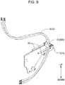
FIG. 9 is a perspective view showing a state in which the hose is fitted to the first clamp member mounted on the support in the hydraulic piping clamp device according to the embodiment of the present invention. -
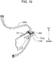
FIG. 10 is a perspective view showing a state in which a second clamp member is mounted on the support of the hydraulic piping clamp device according to the embodiment of the present invention. -
FIG. 11 is a side view showing an engagement state of two adjacent clamp members in the hydraulic piping clamp device according to the embodiment of the present invention. -
FIG. 12 is a perspective view showing a state in which a hose is fitted to the second clamp member mounted on the support in the hydraulic piping clamp device according to the embodiment of the present invention. -
FIG. 13 is a view and its enlarged view showing an engagement state of each of the clamp members when a final clamp member is mounted on the support in the hydraulic piping clamp device according to the embodiment of the present invention. -
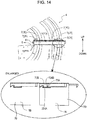
FIG. 14 is a view and its enlarged view showing an engagement state of each of the clamp members when the pressing plate is mounted on the support in the hydraulic piping clamp device according to the embodiment of the present invention. - A hydraulic piping clamp structure (a hydraulic piping clamp device) of a construction machine according to an embodiment of the present invention will be described with reference to
FIGS. 1 to 14 . In the following, a fastener 5 (seeFIGS. 2 and3 ) for clamping thehydraulic hoses 4 of the hydraulic shovel 1 (seeFIG. 1 ) is shown as the hydraulic piping clamp structure of the construction machine. - As shown in
FIG. 1 , thehydraulic shovel 1 has anupper slewing body 10 pivotally mounted on a lower traveling body (not shown). Theupper slewing body 10 has acontrol valve 2, a work attachment 3, and a plurality of hydraulic hoses 4 (one example of hydraulic piping according to the present invention) for connecting thecontrol valve 2 and the work attachment 3 to each other. - The
hydraulic hoses 4 is clamped and routed at a position suitable for the movable region of the work attachment 3 in theupper slewing body 10. Specifically, as shown inFIG. 2 , theupper slewing body 10 of thehydraulic shovel 1 has afastener 5 for fixing (clamping) the plurality ofhydraulic hoses 4 arranged in the vertical direction to the frame body (machine body) of theupper slewing body 10. - As shown in
FIG. 3 , thefastener 5 includes a bracket 6 (support) for supporting the plurality ofhydraulic hoses 4, a plurality ofclamp members 7A-7F mounted on thebracket 6 and apressing plate 8 for pressing the plurality ofclamp members 7A-7F to thebracket 6. - As shown in
FIG. 4 , thebracket 6 includes amounting surface 61, a guide surface 63 (also referred to as an end wall and an end surface) orthogonal to themounting surface 61, and twoguide bars 65. Themounting surface 61 is a surface for mounting thebracket 6 on one surface of the frame body of the upper slewing body 10 (not shown), and theguide surface 63 supports the twoguide bars 65. The twoguide bars 65 extend along a predetermined arrangement direction (DR) from theguide surface 63. The side opposite to theguide surface 63 of thebracket 6 is opened, and thebracket 6 supports the plurality ofhydraulic hoses 4 so that the plurality ofhydraulic hoses 4 are aligned along the arrangement direction parallel to the twoguide bars 65. - The
bracket 6 is attached to theupper slewing body 10 so that themounting surface 61 and theguide surface 63 are perpendicular to each other. As a result, two guide bars vertically arranged with respect to theguide surface 63 extend in the horizontal direction. - Next, referring to
FIGS. 5-7 , a plurality ofclamp members 7A-7F mounted on thebracket 6 will be described. Since the plurality ofclamp members 7A-7F is common components and have exactly the same structure, theclamp members 7A-7F will be described simply as theclamp member 7. - As shown in
FIG. 5 , theclamp member 7 is a U-shaped member in a top view having afitting groove part 71 at the almost center, and clamps thehydraulic hose 4 to thebracket 6. As shown inFIG. 9 , arubber bush 40 attached to thehydraulic hose 4 is fitted to thefitting groove part 71. Thefitting groove part 71 is an example of the holding portion according to the present invention, and in this embodiment, thehydraulic hose 4 is indirectly held in thefitting groove part 71 through therubber bush 40. Therubber bush 40 may be part of thefastener 5 or may be part of thehydraulic hose 4. - As shown in
FIG. 6 , twoinsertion holes 77 for inserting the twoguide bars 65 are formed on both right and left sides of theclamp member 7. As shown inFIG. 8 , theclamp member 7 is mounted on thebracket 6 by inserting theguide bars 65 into theinsertion holes 77 of theclamp member 7. Eachinsertion hole 77 allows theguide bar 65 to be inserted along the arrangement direction DR. The arrangement direction DR may refer to a penetration direction in which theguide bar 65 penetrates through theinsertion hole 77. - By inserting two
insertion holes 77 of each of the plurality ofclamp members 7 in order into the twoguide bars 65, the plurality ofclamp members 7 are mounted on thebrackets 6 so as to be aligned along the arrangement direction DR. - As shown in
FIGS. 5 and7 , theclamp member 7 includes amain body portion 70, and anengaging portion 73 projecting from one end portion (an end portion of themain body portion 70, which is inserted into the guide bar 65) of the arrangement direction DR, in the arrangement direction DR. Theengaging portion 73 is an example of a first engaging portion according to the present invention. - As shown in
FIG. 7 , theengaging portion 73 has an extendingportion 731 extending along the arrangement direction DR, and ahooking portion 733 projecting obliquely downward in an acute angle from the distal end portion (extension destination) of the extendingportion 731. Thehooking portion 733 includes an abutting surface 734 (engaging surface). Theabutting surface 734 is a surface intersecting the arrangement direction and is inclined from the extendingportion 731 toward themain body portion 70. - The
clamp member 7 includes anengaging portion 75 disposed on theupper surface portion 70H of themain body portion 70 at an end portion of themain body portion 70 on the opposite side to the end portion including theengaging portion 73 of the main body portion 70 (opposite to the end portion on the side to be inserted into the guide bar 65). Theengaging portion 75 is an example of a second engaging portion according to the present invention. Theengaging portion 75 has a shape engageable with theengaging portion 73. - Specifically, the
engaging portion 75 has a hookedportion 753 engageable with thehooking portion 733 of theengaging portion 73. The hookedportion 753 has a shape (projection) projecting upward from theupper surface portion 70H in a side view shown inFIG. 7 , and has an abutting surface 754 (engaged surface) engageable with theabutting surface 734. The engagingportion 75 has arecess 75H disposed adjacent to the hookedportion 753 in the arrangement direction DR. Therecess 75H has a shape capable of receiving a hookingportion 733 in a state of being engaged with the hookedportion 753 in theupper surface portion 70H of each of the plurality ofclamp members 7 when viewed in a cross section including the arrangement direction DR and the vertical direction respectively. As shown inFIGS. 6 and7 , the engagingportion 75 is not formed with a side wall in a direction (side direction) orthogonal to the arrangement direction DR and the vertical direction. In other words, in therecess 75H of the engagingportion 75, both ends in a direction orthogonal to the arrangement direction DR and the vertical direction are respectively opened to the outside of theclamp member 7. - Next, referring to
FIG. 8 to FIG. 11 , a procedure for mounting a plurality ofclamp members 7A-7F on thebracket 6 will be described. - First, as shown in
FIG. 8 , the operator inserts the insertion holes 77 (77A) (seeFIG. 6 ) of the first clamp member 7 (7A) into the guide bars 65 of thebracket 6, and inserts and mounts thefirst clamp member 7A into the side of theguide surface 63 of thebracket 6. At this time, the engagingportion 73A (specifically, the hooking portion) of the clamp member 7Ais disposed on the back side of theguide surface 63. As a result, even if theclamp member 7A is shifted in a direction (see the broken line inFIG. 11 ) in which theclamp member 7A is displaced from the guide bars 65, the engagingportion 73A of theclamp member 7A is engaged with the back side of theguide surface 63 to prevent theclamp member 7A from coming off. - Next, as shown in
FIG. 9 , a rubber bush 40 (40A) mounted on the hydraulic hose 4 (4A) is fitted to the fitting groove part 71 (71A) (seeFIG. 5 ) of the first clamp member 7 (7A). - Thereafter, as shown in
FIG. 10 , the operator inserts the insertion holes 77 (77B) (seeFIG. 6 ) of the second clamp members 7 (7B) into the guide bars 65 of thebracket 6, and inserts thesecond clamp member 7B into the side of thefirst clamp member 7A and mounts it. - As shown in
FIG. 11 , in a state where thesecond clamp member 7B is mounted, the engagingportion 73B of theclamp member 7B is disposed in an engagingportion 75A formed on the upper surface of thefirst clamp member 7A. - In order to simplify the description, the
hydraulic hose 4A and therubber bush 40A are omitted inFIG. 11 , but in practice, the hydraulic hose 4Ais fitted into the fitting groove part 71A of thefirst clamp member 7A via therubber bush 40A (seeFIG. 10 ). Therefore, thesecond clamp member 7B may be displaced in the direction (see the broken line inFIG. 11 ) in which thesecond clamp member 7B is dismounted from the guide bars 65 under the influence of the reaction force of thehydraulic hose 4A. In this case, the abuttingsurface 734B of thesecond clamp member 7B abuts on theabutting surface 754A of thefirst clamp member 7A, thereby preventing thesecond clamp member 7B from coming off. - As shown in
FIG. 12 , a rubber bush 40 (40B) attached to the hydraulic hose 4 (4B) is fitted to the fitting groove part 71 (71B) of the second clamp members 7 (7B). - Thereafter, similar procedures are repeated for the third and
subsequent clamp members 7C-7F, and all of theclamp members 7A-7F are mounted on thebracket 6. - When the
last clamp member 7F is mounted on thebracket 6, theclamp members 7A -7F are subjected to a force in the direction of coming off from theguide bar 65 by the influence of the reaction force of thehydraulic hose 4. Therefore, as shown inFIG. 13 , the engagingportion 73B of thesecond clamp member 7B engages with the engagingportion 75A of theadjacent clamp member 7A. Although not shown, the third andsubsequent clamp members 7C are similar. - As shown in
FIGS. 3 and14 , thepressing plate 8 capable of pressing the plurality ofclamp members 7A-7F toward theguide surface 63 is provided on theclamp member 7F (the clamp member disposed at the farthest position from the guide surface 63) that is mounted finally. Thepressing plate 8 is fixed (mounted) to thebracket 6 by fasteningbolts 81 to female screws formed at each the tip of the two guide bars 65. When thepressing plate 8 is mounted by twobolts 81, the plurality ofclamp members 7A-7F are pressed in a state of being sandwiched between theguide surface 63 and thepressing plate 8. In the present embodiment, in the arrangement direction DR, the length dimension of the two guide bars 65 (FIG. 4 ) is set to an integral multiple of the length dimension of themain body portion 70 of the plurality ofclamp members 7. - When the plurality of
clamp members 7A-7F are pressed by thepressing plate 8, the engagement state between the engagingportion 73B of theclamp member 7B and the engagingportion 75A of theclamp member 7A is released, as shown inFIG. 14 . Specifically, theclamp member 7B is brought into close contact with theclamp member 7A, and theabutting surface 734B of theclamp member 7B is separated from the abuttingsurface 754A of theclamp member 7A in the arrangement direction DR. Although not shown, the third andsubsequent clamp members 7C are similar. The engagingportion 73A of thefirst clamp member 7A is also separated from theguide surface 63. - In the above-described embodiment, for example, when the
pressing plate 8 is not mounted on thebracket 6 and the two adjacent clamp members out of the plurality ofclamp members 7A-7F move in a separating direction, the engagingportion 73 of one clamp member and the engagingportion 75 of the other clamp member are engaged with each other. Therefore, when the plurality ofclamp members 7A-7F are assembled, theclamp member 7 does not come off from the guide bars 65. Accordingly, in thehydraulic shovel 1, a plurality ofclamp members 7A-7F used for fastening thehydraulic hoses 4 can be easily assembled to thebracket 6. - Further, in the above-described embodiment, the engaging
portion 73 has the hookingportion 733 projecting obliquely downward in the acute angle from the distal end portion of the extendingportion 731, and the engagingportion 75 has the hookedportion 753 engageable with the hookingportion 733. Therefore, even when an external force is generated in thehydraulic hose 4, the engagement state between the engagingportion 73 and the engagingportion 75 is maintained firmly. - Further, in the above-described embodiment, when the plurality of
clamp members 7A - 7F are pressed by thepressing plate 8, themain body portions 70 of theadjacent clamp members 7 are brought into close contact with each other, and the engagement state between the engagingportion 73 of oneclamp member 7 and the engagingportion 75 of theother clamp member 7 is released (seeFIG. 14 ). In other words, in a state in which the first clamp member of the plurality of clamp members is mounted on thebracket 6, the second clamp member of the plurality of clamp members is attached to thebracket 6, the engagingportion 73 of the second clamp member is disposed at an interval in the arrangement direction with respect to the hookedportion 753 after getting over the hookedportion 753 so that themain body portion 70 of the first clamp member and themain body portion 70 of the second clamp member can be brought into contact with each other in the bracket 6 (FIG. 14 ). The relative positions of the engagingportion 73 and the engagingportion 75 in the arrangement direction DR are set so that the engagingportion 73 of the second clamp member engages with the engagingportion 75 of the first clamp member and prevent themain body portions 70 to further separate when the main bodies of the first and second clamp members mounted on thebracket 6 are relatively moved in a direction away from each other. Therefore, after the assembly of the plurality ofclamp members 7A-7F is completed, a load is not applied to the hookingportion 733 of the engagingportion 73 and the hookedportion 753 of the engagingportion 75 of eachclamp member 7, and breakage of the hookingportion 733 and the hookedportion 753 can be prevented. - In the embodiment described above, since the engaging
portion 75 is formed in theupper surface portion 70H of theclamp member 7, the workability during assembly is high as compared with the case where the engaging portion is formed on a side surface or a bottom surface of theclamp member 7. - In the embodiment described above, since no side wall is formed on the engaging
portion 75 in the direction (lateral direction) orthogonal to the arrangement direction DR and the vertical direction, both ends of therecess 75H are opened to the outside of the clamp member 7 (seeFIGS. 6 and7 ). Therefore, even if dust enters therecess 75H of the engagingportion 75, the dust is easily discharged from both ends of therecess 75H, so that the dust is less likely to deposit on therecess 75H. - The hydraulic piping clamp structure according to the present invention is not limited to the embodiment described above, and various modifications and improvements are possible.
- For example, in the above embodiment, two
guide bars 65 are provided on thebracket 6. However, the present invention is not limited thereto. One guide bar may be provided on thebracket 6, or three or more guide bars may be provided. In this case, the number of insertion holes formed in the clamp member is changed according to the number of guide bars provided in thebracket 6. - In the above embodiment, the case where the
hydraulic hoses 4 connecting thecontrol valve 2 and the work attachment 3 are fastened by thefastener 5 is exemplified, but the hydraulic piping other than thehydraulic hose 4 may be fastened by thefastener 5. - In the above embodiment, the engaging
portion 75, which is an example of the second engaging portion according to the present invention, is formed on the upper surface of theclamp member 7, but the second engaging portion may be formed on the side surface or the bottom surface of theclamp member 7. In this case, the first engaging portion is disposed at a position engageable with the second engaging portion. - In the above embodiment, the case where the
hydraulic hose 4 is indirectly held by thefitting groove part 71 via therubber bush 40 is exemplified, but the present invention is not limited thereto. For example, the shape of thefitting groove part 71 may be changed to a shape corresponding to the outer periphery of thehydraulic hose 4, and thehydraulic hose 4 may be directly held in thefitting groove part 71. - As described above, the hydraulic piping clamp device according to the present invention is suitable for clamping hydraulic hoses connecting a control valve of a hydraulic shovel and a work attachment.
- Provided according to the present invention is a hydraulic piping clamp device for fixing a plurality of hydraulic pipes to a machine body of the construction machine in the construction machine, comprising: a support mounted on the machine body of the construction machine and including an end wall and at least one guide bar extending horizontally from the end wall, a side portion of the support opposite to the end wall being opened, and the support supporting the plurality of hydraulic pipes so that the plurality of hydraulic pipes is aligned along an arrangement direction parallel to the at least one guide bar: and a plurality of clamp members mounted to the support to clamp the plurality of hydraulic pipes on the support, each of the plurality of clamp members having a holding portion holding the hydraulic pipe and being formed of at least one insertion hole for allowing the at least one guide bar to be inserted along the arrangement direction. The plurality of clamp members is mounted on the support so that the plurality of clamp members is aligned along the arrangement direction by inserting the insertion hole of each of the plurality of clamp members in order into the at least one guide bar. Each of the plurality of clamp members includes: a main body portion: a first engaging portion projecting in the arrangement direction from one end portion of the main body portion in the arrangement direction; and a second engaging portion formed at other end portion opposite to the one end portion of the main body portion and having a shape capable of engaging with the first engaging portion. The relative positions of the first engaging portion and the second engaging portion in the arrangement direction are set so that, in a state in which the first clamp member of the plurality of clamp members is mounted on the support and the second clamp member of the plurality of clamp members is further mounted on the support, the first engaging portion of the second clamp member is disposed at an interval in the arrangement direction with respect to the second engaging portion of the first clamp member beyond the second engaging portion of the first clamp member thereby the main body portion of the first clamp member and the main body portion of the second clamp member can be brought into contact with each other in the support, and when the main body portions of the first clamp member and the second clamp member mounted on the support move in a direction away from each other, the first engaging portion of the second clamping member engages with the second engaging portion of the first clamping member to prevent further separate the body portions from each other.
- According to the present invention, when two adjacent clamp members of the plurality of clamp members move in a direction away from each other, the first engaging portion of one of the clamp members engages with the second engaging portion of the other clamp member. Therefore, it is possible to easily assemble a plurality of clamp members used for fastening hydraulic piping in a construction machine.
- In the above configuration, it is desirable that the first engaging portion has an extending portion extending from the main body portion in the arrangement direction and a hooking portion projecting downward from the tip of the extending portion, the second engaging portion has a hooked portion engageable with the hooking portion of the first engaging portion.
- In the above configuration, it is desirable that the hooking portion has an engaging surface that intersects the arrangement direction and is inclined from the extending portion toward the main body portion, each of the main body portions of the plurality of clamp members has an upper surface portion, the hooked portion has a projection projecting upward from a part of the upper surface, and the projection has an engaged surface engageable with the engaging surface.
- In the above configuration, it is desirable that the hydraulic piping clamp device further comprises a pressing plate that abuts against a clamping member disposed at a position farthest from the end wall of the support out of the plurality of clamp members and is mounted on the support to press the plurality of clamp members toward the end wall, the relative position of the hooking portion and the hooked portion in the arrangement direction is set so that the hooking portion of the second clamp member can be engaged with the hooked portion of the first clamp member in a state in which the pressing plate is not mounted on the support, and the hooking portion of the second clamping member is separated from the hooked portion of the first clamping member along the arrangement direction in a state in which the pressing plate is mounted on the support.
- In the above configuration, it is desirable that the hydraulic piping is a hydraulic hose connecting a control valve of the construction machine and a work attachment to each other, each of the holding portions of the plurality of clamp members can directly or indirectly hold the hydraulic hose routed in the vertical direction, the second engaging portion further includes a recess disposed adjacent to the projection in the arrangement direction and on the upper surface portion of each of the plurality of clamp members when viewed in a cross section including the arrangement direction and the vertical direction, and capable of receiving the hooking portion in a state of being engaged with the hooked portion.
- In the above configuration, it is desirable that both ends of the recess of the second engaging portion in a direction orthogonal to the arrangement direction and the vertical direction are respectively opened to the outside of the clamp member.
Claims (6)
- A hydraulic piping clamp device for fixing a plurality of hydraulic pipes to a machine body of the construction machine in the construction machine, comprising:a support mounted on the machine body of the construction machine and including an end wall and at least one guide bar extending horizontally from the end wall, a side portion of the support opposite to the end wall being opened, and the support supporting the plurality of hydraulic pipes so that the plurality of hydraulic pipes is aligned along an arrangement direction parallel to the at least one guide bar: anda plurality of clamp members mounted to the support to clamp the plurality of hydraulic pipes on the support, each of the plurality of clamp members having a holding portion holding the hydraulic pipe and being formed of at least one insertion hole for allowing the at least one guide bar to be inserted along the arrangement direction, whereinthe plurality of clamp members is mounted on the support so that the plurality of clamp members is aligned along the arrangement direction by inserting the insertion hole of each of the plurality of clamp members in order into the at least one guide bar,each of the plurality of clamp members includes:a main body portion:a first engaging portion projecting in the arrangement direction from one end portion of the main body portion in the arrangement direction; anda second engaging portion formed at other end portion opposite to the one end portion of the main body portion and having a shape capable of engaging with the first engaging portion;the relative positions of the first engaging portion and the second engaging portion in the arrangement direction are set so that, in a state in which the first clamp member of the plurality of clamp members is mounted on the support and the second clamp member of the plurality of clamp members is further mounted on the support, the first engaging portion of the second clamp member is disposed at an interval in the arrangement direction with respect to the second engaging portion of the first clamp member beyond the second engaging portion of the first clamp member, thereby the main body portion of the first clamp member and the main body portion of the second clamp member can be brought into contact with each other in the support, and when the main body portions of the first clamp member and the second clamp member mounted on the support move in a direction away from each other, the first engaging portion of the second clamping member engages with the second engaging portion of the first clamping member to prevent further separate the body portions from each other.
- The hydraulic piping clamp device of the construction machine according to claim 1, whereinthe first engaging portion has an extending portion extending from the main body portion in the arrangement direction and a hooking portion projecting downward from the tip of the extending portion,the second engaging portion has a hooked portion engageable with the hooking portion of the first engaging portion.
- The hydraulic piping clamp device of the construction machine according to claim 2, whereinthe hooking portion has an engaging surface that intersects the arrangement direction and is inclined from the extending portion toward the main body portion,each of the main body portions of the plurality of clamp members has an upper surface portion,the hooked portion has a projection projecting upward from a part of the upper surface, and the projection has an engaged surface engageable with the engaging surface.
- The hydraulic piping clamp device of the construction machine according to claim 2, further comprising:a pressing plate that abuts against a clamping member disposed at a position farthest from the end wall of the support out of the plurality of clamp members and is mounted on the support to press the plurality of clamp members toward the end wall,the relative position of the hooking portion and the hooked portion in the arrangement direction is set so that the hooking portion of the second clamp member can be engaged with the hooked portion of the first clamp member in a state in which the pressing plate is not mounted on the support, and the hooking portion of the second clamping member is separated from the hooked portion of the first clamping member along the arrangement direction in a state in which the pressing plate is mounted on the support.
- The hydraulic piping clamp device of the construction machine according to claim 4, whereinthe hydraulic piping is a hydraulic hose connecting a control valve of the construction machine and a work attachment to each other,each of the holding portions of the plurality of clamp members can directly or indirectly hold the hydraulic hose routed in the vertical direction,the second engaging portion further includes a recess disposed adjacent to the projection in the arrangement direction and on the upper surface portion of each of the plurality of clamp members when viewed in a cross section including the arrangement direction and the vertical direction, and capable of receiving the hooking portion in a state of being engaged with the hooked portion.
- The hydraulic piping clamp device of the construction machine according to claim 5, wherein
both ends of the recess of the second engaging portion in a direction orthogonal to the arrangement direction and the vertical direction are respectively opened to the outside of the clamp member.
Applications Claiming Priority (2)
| Application Number | Priority Date | Filing Date | Title |
|---|---|---|---|
| JP2019088139A JP6760438B1 (en) | 2019-05-08 | 2019-05-08 | Hydraulic piping clamp structure for construction machinery |
| PCT/JP2020/012246 WO2020225986A1 (en) | 2019-05-08 | 2020-03-19 | Hydraulic piping clamp device for construction machine |
Publications (2)
| Publication Number | Publication Date |
|---|---|
| EP3933115A1 true EP3933115A1 (en) | 2022-01-05 |
| EP3933115A4 EP3933115A4 (en) | 2022-12-21 |
Family
ID=72517968
Family Applications (1)
| Application Number | Title | Priority Date | Filing Date |
|---|---|---|---|
| EP20802542.9A Withdrawn EP3933115A4 (en) | 2019-05-08 | 2020-03-19 | Hydraulic piping clamp device for construction machine |
Country Status (5)
| Country | Link |
|---|---|
| US (1) | US20220349152A1 (en) |
| EP (1) | EP3933115A4 (en) |
| JP (1) | JP6760438B1 (en) |
| CN (1) | CN113614316B (en) |
| WO (1) | WO2020225986A1 (en) |
Families Citing this family (1)
| Publication number | Priority date | Publication date | Assignee | Title |
|---|---|---|---|---|
| JP7358306B2 (en) * | 2020-08-03 | 2023-10-10 | 株式会社クボタ | work vehicle |
Family Cites Families (13)
| Publication number | Priority date | Publication date | Assignee | Title |
|---|---|---|---|---|
| CH397021A (en) * | 1961-12-11 | 1965-08-15 | Fischer Artur | Plastic pipe clamp for laying individual electrical cables or pipes of various diameters |
| US3464661A (en) * | 1967-08-15 | 1969-09-02 | Formex Mfg Inc | Conduit spacer apparatus |
| US4036289A (en) * | 1975-01-20 | 1977-07-19 | General Atomic Company | Heat exchanger tube bundle support system |
| US5104072A (en) * | 1990-12-26 | 1992-04-14 | Kuo Chun Hua | Insert type of disengageable underground conduit holder |
| US7497718B2 (en) * | 2006-11-08 | 2009-03-03 | International Truck Intellectual Property Company, Llc | Routing clip elements with a living hinge and interlocking closure |
| JP4757272B2 (en) * | 2008-03-07 | 2011-08-24 | 日立建機株式会社 | Hydraulic hose clamp device for construction machinery |
| JP2010116947A (en) * | 2008-11-11 | 2010-05-27 | Maruyasu Industries Co Ltd | Collecting pipe and its manufacturing method |
| US8702044B2 (en) * | 2009-02-04 | 2014-04-22 | The Gates Corporation | Conduit bracketry, systems and methods |
| JP5510488B2 (en) * | 2012-03-29 | 2014-06-04 | コベルコ建機株式会社 | Work machine |
| JP5949076B2 (en) * | 2012-04-09 | 2016-07-06 | コベルコ建機株式会社 | Work machine |
| DE202015007620U1 (en) * | 2015-11-04 | 2015-12-15 | Fkb Gmbh | Guide or holding device for holding pipes, cables or hoses |
| DE202017105636U1 (en) * | 2017-09-18 | 2017-10-02 | Obo Bettermann Hungary Kft | clamp clip |
| WO2019142929A1 (en) * | 2018-01-19 | 2019-07-25 | 株式会社 潤工社 | Supporting member, conduit supporting device, and processing apparatus provided therewith |
-
2019
- 2019-05-08 JP JP2019088139A patent/JP6760438B1/en active Active
-
2020
- 2020-03-19 CN CN202080027327.1A patent/CN113614316B/en active Active
- 2020-03-19 EP EP20802542.9A patent/EP3933115A4/en not_active Withdrawn
- 2020-03-19 WO PCT/JP2020/012246 patent/WO2020225986A1/en not_active Ceased
- 2020-03-19 US US17/605,045 patent/US20220349152A1/en not_active Abandoned
Also Published As
| Publication number | Publication date |
|---|---|
| EP3933115A4 (en) | 2022-12-21 |
| US20220349152A1 (en) | 2022-11-03 |
| JP2020183656A (en) | 2020-11-12 |
| WO2020225986A1 (en) | 2020-11-12 |
| JP6760438B1 (en) | 2020-09-23 |
| CN113614316A (en) | 2021-11-05 |
| CN113614316B (en) | 2022-07-19 |
Similar Documents
| Publication | Publication Date | Title |
|---|---|---|
| EP2644782B1 (en) | Hydraulic hose routing for a working machine | |
| JP5177201B2 (en) | Piping clamp for construction machinery | |
| EP2725150A1 (en) | Rotation-type construction machine | |
| JP6523426B2 (en) | Mounting bracket, mounting unit, and railway vehicle | |
| TW202211838A (en) | Slide rail kit | |
| JP6806929B2 (en) | Mounting plate assembly and its mounting method | |
| US20220349152A1 (en) | Hydraulic piping clamp device for construction machine | |
| US8366068B2 (en) | Bracing structure, fastener and method for bracing a support structure having props for ceiling formworks | |
| KR101014030B1 (en) | Wiring Mounting Flange and Manufacturing Process | |
| KR20090054179A (en) | Side clamp | |
| JP6501299B2 (en) | Protector | |
| KR20190021039A (en) | Graiting stopper | |
| JP5945406B2 (en) | Scaffolding plate connector | |
| JP4808008B2 (en) | Vehicle engine mounting structure | |
| CN113459801A (en) | Mounting structure of adsorption tank | |
| KR102148090B1 (en) | Fluid control device and method of attaching and detaching gas line part | |
| JP6210776B2 (en) | Passenger conveyor skirt guard attaching / detaching device | |
| JP7409534B1 (en) | Elevator guide rail fixing device | |
| JP7223440B2 (en) | equipotential bonding fittings | |
| JP2021066277A (en) | Railway vehicle interior part fitting structure | |
| KR101529329B1 (en) | Harness retaining clip with tie wrap | |
| JP5875774B2 (en) | Fence panel mounting bracket, mounting structure and mounting method | |
| KR101570280B1 (en) | Fluid control device | |
| KR20210000082A (en) | Solar module fixing structure | |
| JP3159250U (en) | Skirting clamp |
Legal Events
| Date | Code | Title | Description |
|---|---|---|---|
| STAA | Information on the status of an ep patent application or granted ep patent |
Free format text: STATUS: THE INTERNATIONAL PUBLICATION HAS BEEN MADE |
|
| PUAI | Public reference made under article 153(3) epc to a published international application that has entered the european phase |
Free format text: ORIGINAL CODE: 0009012 |
|
| STAA | Information on the status of an ep patent application or granted ep patent |
Free format text: STATUS: REQUEST FOR EXAMINATION WAS MADE |
|
| 17P | Request for examination filed |
Effective date: 20211001 |
|
| AK | Designated contracting states |
Kind code of ref document: A1 Designated state(s): AL AT BE BG CH CY CZ DE DK EE ES FI FR GB GR HR HU IE IS IT LI LT LU LV MC MK MT NL NO PL PT RO RS SE SI SK SM TR |
|
| DAV | Request for validation of the european patent (deleted) | ||
| DAX | Request for extension of the european patent (deleted) | ||
| A4 | Supplementary search report drawn up and despatched |
Effective date: 20221121 |
|
| RIC1 | Information provided on ipc code assigned before grant |
Ipc: F16L 3/22 20060101ALI20221115BHEP Ipc: E02F 9/00 20060101AFI20221115BHEP |
|
| GRAP | Despatch of communication of intention to grant a patent |
Free format text: ORIGINAL CODE: EPIDOSNIGR1 |
|
| STAA | Information on the status of an ep patent application or granted ep patent |
Free format text: STATUS: GRANT OF PATENT IS INTENDED |
|
| INTG | Intention to grant announced |
Effective date: 20230810 |
|
| STAA | Information on the status of an ep patent application or granted ep patent |
Free format text: STATUS: THE APPLICATION IS DEEMED TO BE WITHDRAWN |
|
| 18D | Application deemed to be withdrawn |
Effective date: 20231221 |