EP3933026A1 - Electrode substrate, measurement device, removal tool, and measurement method - Google Patents
Electrode substrate, measurement device, removal tool, and measurement method Download PDFInfo
- Publication number
- EP3933026A1 EP3933026A1 EP20762477.6A EP20762477A EP3933026A1 EP 3933026 A1 EP3933026 A1 EP 3933026A1 EP 20762477 A EP20762477 A EP 20762477A EP 3933026 A1 EP3933026 A1 EP 3933026A1
- Authority
- EP
- European Patent Office
- Prior art keywords
- electrode
- electrode substrate
- substrate
- base section
- extension part
- Prior art date
- Legal status (The legal status is an assumption and is not a legal conclusion. Google has not performed a legal analysis and makes no representation as to the accuracy of the status listed.)
- Pending
Links
Images







Classifications
-
- C—CHEMISTRY; METALLURGY
- C12—BIOCHEMISTRY; BEER; SPIRITS; WINE; VINEGAR; MICROBIOLOGY; ENZYMOLOGY; MUTATION OR GENETIC ENGINEERING
- C12M—APPARATUS FOR ENZYMOLOGY OR MICROBIOLOGY; APPARATUS FOR CULTURING MICROORGANISMS FOR PRODUCING BIOMASS, FOR GROWING CELLS OR FOR OBTAINING FERMENTATION OR METABOLIC PRODUCTS, i.e. BIOREACTORS OR FERMENTERS
- C12M41/00—Means for regulation, monitoring, measurement or control, e.g. flow regulation
- C12M41/46—Means for regulation, monitoring, measurement or control, e.g. flow regulation of cellular or enzymatic activity or functionality, e.g. cell viability
-
- G—PHYSICS
- G01—MEASURING; TESTING
- G01N—INVESTIGATING OR ANALYSING MATERIALS BY DETERMINING THEIR CHEMICAL OR PHYSICAL PROPERTIES
- G01N33/00—Investigating or analysing materials by specific methods not covered by groups G01N1/00 - G01N31/00
- G01N33/48—Biological material, e.g. blood, urine; Haemocytometers
- G01N33/483—Physical analysis of biological material
- G01N33/4833—Physical analysis of biological material of solid biological material, e.g. tissue samples, cell cultures
- G01N33/4836—Physical analysis of biological material of solid biological material, e.g. tissue samples, cell cultures using multielectrode arrays
-
- G—PHYSICS
- G01—MEASURING; TESTING
- G01N—INVESTIGATING OR ANALYSING MATERIALS BY DETERMINING THEIR CHEMICAL OR PHYSICAL PROPERTIES
- G01N27/00—Investigating or analysing materials by the use of electric, electrochemical, or magnetic means
- G01N27/02—Investigating or analysing materials by the use of electric, electrochemical, or magnetic means by investigating impedance
- G01N27/04—Investigating or analysing materials by the use of electric, electrochemical, or magnetic means by investigating impedance by investigating resistance
- G01N27/12—Investigating or analysing materials by the use of electric, electrochemical, or magnetic means by investigating impedance by investigating resistance of a solid body in dependence upon absorption of a fluid; of a solid body in dependence upon reaction with a fluid, for detecting components in the fluid
- G01N27/125—Composition of the body, e.g. the composition of its sensitive layer
-
- G—PHYSICS
- G01—MEASURING; TESTING
- G01N—INVESTIGATING OR ANALYSING MATERIALS BY DETERMINING THEIR CHEMICAL OR PHYSICAL PROPERTIES
- G01N27/00—Investigating or analysing materials by the use of electric, electrochemical, or magnetic means
- G01N27/26—Investigating or analysing materials by the use of electric, electrochemical, or magnetic means by investigating electrochemical variables; by using electrolysis or electrophoresis
- G01N27/28—Electrolytic cell components
- G01N27/30—Electrodes, e.g. test electrodes; Half-cells
- G01N27/327—Biochemical electrodes, e.g. electrical or mechanical details for in vitro measurements
-
- G—PHYSICS
- G01—MEASURING; TESTING
- G01N—INVESTIGATING OR ANALYSING MATERIALS BY DETERMINING THEIR CHEMICAL OR PHYSICAL PROPERTIES
- G01N33/00—Investigating or analysing materials by specific methods not covered by groups G01N1/00 - G01N31/00
- G01N33/48—Biological material, e.g. blood, urine; Haemocytometers
- G01N33/483—Physical analysis of biological material
- G01N33/4833—Physical analysis of biological material of solid biological material, e.g. tissue samples, cell cultures
Definitions
- the present invention relates to a technique for measuring the electrical resistance of biological cells or tissues.
- TEER transepithelial electrical resistance
- Patent Literature 1 discloses a technique for measuring the electrical resistance of cells by immersing elongated chopstick-shaped electrodes in a culture solution.
- Patent Literature 2 discloses a technique for measuring electrical resistance while maintaining a culture environment, with electrodes provided in a lid part of a culture vessel and inside the vessel.
- a first aspect of the present invention is intended for an electrode substrate having electrodes for measuring an electrical resistance of biological cells or tissues.
- the electrode substrate comprises: a substrate having a base section, a first extension part extending from the base section, and a second extension part extending from the base section; a plurality of connection terminals provided on a surface of the base section; a first working electrode and a second working electrode each connected to one of the connection terminals, the first and second working electrodes being wired on a surface of the substrate; and an engagement surface provided on the substrate and facing toward the connection terminals in a position closer to the first extension part than the connection terminals, the first working electrode being wired from the base section to the first extension part, the second working electrode being wired from the base section to the second extension part.
- a second aspect of the present invention is intended for the electrode substrate of the first aspect, wherein the engagement surface is provided on an engagement part provided on a side edge of the substrate and having a protruding or recessed shape.
- a third aspect of the present invention is intended for the electrode substrate of the second aspect, wherein the engagement part is provided in the base section.
- a fourth aspect of the present invention is intended for the electrode substrate of the second or third aspect, wherein the first extension part extends in a first direction from a side edge of the base section, and wherein the engagement part has a shape protruding or recessed in a second direction orthogonal to the first direction.
- a fifth aspect of the present invention is intended for the electrode substrate of the fourth aspect, which further comprises a first reference electrode and a second reference electrode each connected to one of the connection terminals, the first and second reference electrodes being wired on the surface of the substrate.
- a sixth aspect of the present invention is intended for the electrode substrate of the fifth aspect, wherein the first reference electrode is wired from the base section to the first extension part.
- a seventh aspect of the present invention is intended for the electrode substrate of the sixth aspect, wherein the first working electrode is wired on one main surface of the first extension part, and wherein the first reference electrode is wired on the other main surface of the first extension part.
- An eighth aspect of the present invention is intended for the electrode substrate of any one of the fifth to seventh aspects, wherein the base section has a through hole, and wherein one of the first working electrode and the first reference electrode is wired from one main surface of the base section through the through hole onto the other main surface of the base section.
- a ninth aspect of the present invention is intended for a measuring device for measuring an electrical resistance of biological cells or tissues.
- the measuring device comprises: an electrode substrate having electrodes; and a relay section to which the electrode substrate is to be removably attached, wherein the electrode substrate includes a substrate having a base section, a first extension part extending from the base section, and a second extension part extending from the base section, a plurality of connection terminals provided on a surface of the base section, a first working electrode and a second working electrode each connected to one of the connection terminals, the first and second working electrodes being wired on a surface of the substrate, and an engagement surface provided on the substrate and facing toward the connection terminals in a position closer to the first extension part than the connection terminals, the first working electrode being wired from the base section to the first extension part, the second working electrode being wired from the base section to the second extension part, and wherein the relay section includes a plurality of contact parts for contact with the respective connection terminals.
- a tenth aspect of the present invention is intended for the measuring device of the ninth aspect, wherein the relay section further includes an insertion port for insertion of the base section of the electrode substrate therein, and wherein the contact parts are provided inside the insertion port.
- An eleventh aspect of the present invention is intended for the measuring device of the tenth aspect, wherein the engagement surface of the electrode substrate is exposed to the outside of the insertion port, with the base section of the electrode substrate inserted in the insertion port of the relay section.
- a twelfth aspect of the present invention is intended for the measuring device of any one of the ninth to eleventh aspects, wherein the contact parts provided in the relay section are provided in conformity with an SD standard.
- a thirteenth aspect of the present invention is intended for a removal tool for removing the electrode substrate from the relay section in a measuring device as recited in any one of the ninth to twelfth aspects.
- the removal tool comprises a removal part provided with an opening part for insertion of the electrode substrate therein, wherein the opening part includes a first opening greater than part of the electrode substrate where the engagement surface is provided, and a second opening continuous with the first opening and smaller than the part of the electrode substrate where the engagement surface is provided.
- a fourteenth aspect of the present invention is intended for a measuring method for measuring an electrical resistance of biological cells or tissues by means of a measuring system, the measuring system including an electrode substrate, a relay section to which the electrode substrate is to be attached, and a removal tool for removing the electrode substrate from the relay section, the electrode substrate including a substrate having a base section, a first extension part extending from the base section, and a second extension part extending from the base section, a plurality of connection terminals provided on a surface of the base section, a first working electrode and a second working electrode each connected to one of the connection terminals, the first and second working electrodes being wired on a surface of the substrate, and an engagement surface provided on the substrate and facing toward the connection terminals in a position closer to the first extension part than the connection terminals, the removal tool including a removal part provided with an opening part for insertion of the electrode substrate therein, the opening part including a first opening greater than part of the electrode substrate where the engagement surface is provided, and a second opening continuous with the first opening and smaller
- the first working electrode and the second working electrode are electrically connected through the connection terminals of the electrode substrate to the relay section of the measuring device.
- the replacement of the electrodes is achieved by the replacement of the electrode substrate.
- the provision of the engagement surface facing toward the connection terminals side on the electrode substrate allows the engagement part to be urged in a direction opposite the connection terminals while the removal tool is in engagement with the engagement surface. This facilitates the removal of the electrode substrate connected to the relay section. Therefore, the electrical resistance of the cells or tissues is measured with high efficiency and with high accuracy because the replacement of the electrodes is facilitated.
- the removal of the electrode substrate from the relay section is facilitated by bringing the removal tool into engagement with the engagement part having the protruding or recessed shape.
- the deformation of the substrate is reduced if the removal tool is in engagement with the engagement surface and a force is applied thereto.
- the electrode substrate is urged in the first direction by bringing the removal tool into engagement with the engagement part. This allows the electrode substrate to be removed from the relay section in the first direction.
- the electric potential applied to the cells or tissues is measured between the first reference electrode and the second reference electrode. Since the electric potential applied between the first reference electrode and the second working electrode is determined from this measurement value, the electrical resistance of the cells or tissues is measure more accurately.
- the electrode substrate is reduced in size because the first working electrode and the first reference electrode are provided on the common first extension part.
- the electrodes are placed on the main surfaces on both sides of the first extension part, whereby regions of the respective main surfaces are effectively used. Also, the first working electrode and the first reference electrode are insulated by the first extension part. In addition, the first working electrode and the first reference electrode are disposed close to each other.
- the electrodes are wired on the main surfaces on both sides of the base section, whereby regions of the respective main surfaces are effectively used.
- the electrode substrate which includes the plurality of connection terminals, is attachable to and removable from the relay section, so that the replacement of the electrodes is facilitated. Also, the provision of the engagement surface facing toward the connection terminals on the electrode substrate allows the electrode substrate to be urged in a direction opposite the connection terminals while the removal tool is in engagement with the engagement surface. This facilitates the removal of the electrode substrate connected to the relay section through the connection terminals. Therefore, the electrical resistance of the cells or tissues is measured with high efficiency and with high accuracy because the replacement of the electrodes is achieved by the replacement of the electrode substrate.
- connection terminals provided on the electrode substrate are brought into contact with the contact parts of the relay section by inserting the electrode substrate into the insertion port of the relay section. This facilitates the attachment of the electrode substrate to the relay section.
- the removal tool is brought into engagement with the engagement surface of the electrode substrate inserted into the insertion port of the relay section because the engagement surface is exposed to the outside of the insertion port.
- an adapter in conformity with SD standards can be used for the relay section. This reduces the manufacturing costs of the measuring device.
- part of the engagement surface of the electrode substrate is inserted into the first opening. Thereafter, the electrode substrate is moved to the inside of the second opening, and is then withdrawn. Thus, the engagement surface is brought into engagement with the removal part. This allows the removal of the electrode substrate from the relay section.
- the part of the electrode substrate where the engagement surface is provided is inserted into the first opening. Thereafter, the electrode substrate is moved to the second opening, and is then withdrawn. Thus, the second opening is brought into engagement with the engagement surface. This facilitates the removal of the electrode substrate connected to the relay section. Therefore, the electrical resistance of the cells or tissues is measured with high efficiency and with high accuracy because the replacement of the electrodes is facilitated.
- Fig. 1 is a view showing a measuring device 1.
- the measuring device 1 has a configuration suitable for measuring the electrical resistance of biological cells or tissues.
- the measuring device 1 includes a relay section 2 and an electrode substrate 3.
- the relay section 2 is fixed to a robot arm 9 by a fixing method such as screwing.
- the robot arm 9 moves in three-dimensional space in accordance with the driving force of a motor (driving part) that operates under the control of a computer not shown.
- the electrode substrate 3 is attached to the relay section 2.
- the electrode substrate 3 is removably attached to the relay section 2 by being inserted into an insertion port 231 of a housing 23 provided in the relay section 2.
- a longitudinal direction of the electrode substrate 3 which is parallel to a main surface (a first main surface 411 of a base section 41 to be described later) is referred to as a first direction D1
- a direction parallel to the main surface of the electrode substrate 3 and orthogonal to the first direction D1 is referred to as a second direction D2, based on a condition where the electrode substrate 3 is attached to the relay section 2, as shown in Fig. 1 .
- a direction orthogonal to both the first direction D1 and the second direction D2 (the thickness direction of the base section 41 in the electrode substrate 3) is referred as a third direction D3 (with reference to Fig. 6 ).
- Fig. 2 is a view showing the relay section 2.
- the relay section 2 includes a relay board 21 and the housing 23.
- the relay board 21 is a flat plate member made of an insulative material such as epoxy resin or glass epoxy resin.
- the housing 23 is provided on an end portion of one main surface 211 of the relay board 21 on one side as seen in the first direction D1 and in the middle thereof as seen in the second direction D2.
- the housing 23 includes the insertion port 231 that opens toward the one side as seen in the first direction D1.
- the housing 23 has an interior (i.e., inside of the insertion port 231) sized to accommodate the base section 41 of the electrode substrate 3.
- a plurality of (in this embodiment, eight) contact parts 25 are mounted in an array along the second direction D2.
- the contact parts 25 are connected to a cable 27.
- the cable 27 is connected to a device for measuring electrical resistance, such as a power supply 11 or a voltmeter 13 (with reference to Fig. 9 ).
- the number and position of contact parts 25 inside the housing 23 coincide with the number (eight) and position of contact parts provided in an adapter in conformity with Micro SD standards, for example.
- a board for a card reader in conformity with the Micro SD standards can be used for the relay board 21. This reduces the production costs of the relay section 2.
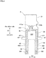
- Fig. 3 is a plan view showing the electrode substrate 3.
- Fig. 4 is a plan view showing the electrode substrate 3.
- Fig. 3 is a view showing a first main surface 311 side of a substrate 31, and
- Fig. 4 is a view showing a second main surface 312 side opposite the first main surface 311 of the substrate 31.
- the electrode substrate 3 includes the substrate 31, a plurality of connection terminals 33, a first working electrode 35, a first reference electrode 36, a second working electrode 37, and a second reference electrode 38.
- the first working electrode 35, the first reference electrode 36, the second working electrode 37, and the second reference electrode 38 are generically referred to as "electrodes 35 to 38" in some cases in the following description.
- the substrate 31 is a rigid, flat plate member made of an insulative material such as epoxy resin or glass epoxy resin.
- the substrate 31 includes the base section 41, a first extension part 43, a second extension part 45, and two protruding parts 47.
- the base section 41, the first extension part 43, the second extension part 45, and the two protruding parts 47 are formed integrally and have the same thickness. However, some or all of these parts may be members provided independently of other elements. As shown in Fig. 1 , the first extension part 43, the second extension part 45, and the two protruding parts 47 are exposed to the outside of the housing 23, with the electrode substrate 3 attached to the relay section 2.
- the substrate 31 has the first main surface 311 and the second main surface 312 on the side opposite the first main surface 311.
- the term "main surfaces” used herein refer to surfaces having the largest area.
- the first main surface 311 of the substrate 31 includes the first main surface 411 of the base section 41, a first main surface 431 (one main surface) of the first extension part 43, and a first main surface 451 of the second extension part 45.
- the second main surface 312 of the substrate 31 includes a second main surface 412 of the base section 41, a second main surface 432 (the other main surface) of the first extension part 43, and a second main surface 452 of the second extension part 45.
- the outer shape of the base section 41 as seen in plan view is similar to that of a typical Micro SD card.
- a locking part 410 having an uneven shape similar to that of a Micro SD card is provided on one side of the base section 41 as seen in the second direction D2.
- an L-shaped plate spring 233 provided on one side in the housing 23 engages a recessed portion of the locking part 410 of the base section 41 (with reference to Fig. 1 ).
- a spring mechanism or the like for urging the electrode substrate 3 toward one side of the first direction D1 may be provided inside the housing 23.
- Two through holes 413a and 413b are formed in the middle part of the base section 41 as seen in the first direction D1 and the second direction D2.
- the through holes 413a and 413b are positioned between a wiring part of the first working electrode 35 and a wiring part of the second working electrode 37.
- a wiring part of the first reference electrode 36 is provided in the through hole 413a, and a wiring part of the second reference electrode 38 is provided in the through hole 413b.
- the first extension part 43 and the second extension part 45 are plate-like parts extending outwardly from different portions at a side edge of the base section 41.
- the term "side edge” used herein refers to a peripheral edge portion sandwiched between the outer peripheral portions of the first main surface 411 and the second main surface 412 of the base section 41.
- Base end portions of the respective extension parts 43 and 45 are connected to a side edge portion of the base section 41 on one side as seen in the first direction D1, and the extension parts 43 and 45 extend in the first direction D1.
- the extension parts 43 and 45 are spaced apart from each other in the second direction D2.
- the width W11 of the first extension part 43 as measured in the second direction D2 and the width W12 of the second extension part 45 as measured in the second direction D2 are less than the width W21 of the base section 41 as measured in the second direction D2.
- the shape and size of the first extension part 43 are the same as those of the second extension part 45 in this embodiment, the shape or size of the first extension part 43 may be different from that of the second extension part 45.
- One protruding part 47 is provided on each side of the base section 41 in the second direction D2.
- the protruding parts 47 on both sides are provided in the same position with respect to the first direction D1.
- the protruding parts 47 are parts of the base section 41 which protrude in the second direction D2 from other parts (e.g., parts inserted in the housing 23).
- the width W1 (with reference to Figs. 1 and 3 ) between the tips of the protruding parts 47 as measured in the second direction D2 is greater than the width W2 (with reference to Figs. 1 and 2 ) of the insertion port 231 of the housing 23 as measured in the second direction D2.
- the width of the electrode substrate 3 is the largest in portions where the protruding parts 47 are provided on both sides. In other words, the width W1 is the largest width in the electrode substrate 3.
- the protruding parts 47 provided on both sides of the base section 41 are used for the removal of the electrode substrate 3 attached to the relay section 2.
- Each of the protruding parts 47 has an engagement surface 471 facing toward the connection terminals 33 side (the other side of the first direction).
- the expression "the engagement surface faces toward the connection terminals” means that the direction of the normal to the engagement surface is parallel to a terminal side direction toward the connection terminals or is a direction having at least a component of the terminal side direction (i.e., a direction not perpendicular to the terminal side direction).
- the engagement surfaces 471 engage a lid part 53 (removal part) of a removal tool 5, so that the protruding parts 47 are urged toward the side opposite the connection terminals 33 (one side of the first direction D1). This urging force allows the electrode substrate to be removed from the relay section 2.
- connection terminals 33 are provided on the first main surface 311 of the base section 41. Terminal parts of the electrodes 35 to 38 are connected to the connection terminals 33. In this embodiment, each of the electrodes 35 to 38 is connected to adjacent two of the connection terminals 33.
- the first working electrode 35 is connected to adjacent two of the connection terminals 33, and has wiring parts meeting in an intermediate position in the base section 41. In other words, the first working electrode 35 branches from one wiring part into two wiring parts in the base section 41, and each of the two wiring parts is connected to one of the two adjacent connection terminals 33.
- the electrodes 35 to 38 are wired on the surface of the substrate 31.
- the wiring for the electrodes 35 to 38 are provided on the surface of the substrate 31 by various methods such as etching and direct drawing, for example.
- the electrodes 35 to 38 are arranged in the order named along the second direction D2.
- the order of arrangement of the electrodes 35 to 38 is not limited to this but may be changed as appropriate.
- the first working electrode 35 is wired from the base section 41 to the first extension part 43, and is provided on the first main surface 311 side of the substrate 31 (with reference to Fig. 3 ). Specifically, the first working electrode 35 is provided on the first main surface 411 of the base section 41 and on the first main surface 431 of the first extension part 43.
- the first reference electrode 36 is wired from the base section 41 to the first extension part 43 (with reference to Fig. 4 ). Specifically, the wiring part extending from the two connection terminals 33 to the through hole 413a is provided on the first main surface 311 side of the substrate 31, and the wiring part beyond the through hole 413a is provided on the second main surface 312 side of the substrate 31. That is, the first reference electrode 36 is wired on the second main surface 432 of the first extension part 43.
- the second working electrode 37 is wired from the base section 41 to the second extension part 45, and is provided on the first main surface 311 side of the substrate 31 (with reference to Fig. 3 ). Specifically, the second working electrode 37 is provided on the first main surface 411 of the base section 41 and on the first main surface 451 of the second extension part 45.
- the second reference electrode 38 is wired from the base section 41 to the second extension part 45 (with reference to Fig. 4 ). Specifically, the wiring part extending from the two connection terminals 33 to the through hole 413b is provided on the first main surface 311 side of the substrate 31, and the wiring part beyond the through hole 413b is provided on the second main surface 312 side of the substrate 31. That is, the second reference electrode 38 is wired on the second main surface 452 of the second extension part 45.
- the wiring parts of the electrodes 35 to 38 are covered with a resist 49 that is an insulator, and terminal parts 351, 361, 371, and 381 provided in the first extension part 43 and the second extension part 45 are exposed to the outside.
- the terminal parts 351, 361, 371, and 381 are parts to be immersed in the culture solution during the measurement of the electrical resistance.
- the tip of the first extension part 43 and the tip of the second extension part 45 are spaced apart in the second direction D2. For this reason, the terminal part 351 of the first working electrode 35 and 371 of the second working electrode 37 are disposed in positions separated in the second direction D2 (with reference to Fig. 3 ). Also, the terminal parts 361 and 381 of the reference electrodes 36 and 38 are disposed in positions separated in the second direction D2 (with reference to Fig. 4 ).
- the two electrodes 35 and 36 are provided on the common first extension part 43, whereby the electrode substrate 3 is reduced in size.
- the two electrodes 37 and 38 are provided on the common second extension part 45, whereby the electrode substrate 3 is reduced in size.
- the electrodes 35 and 36 are provided respectively on the main surfaces 431 and 432 on both sides of the first extension part 43, whereby the region of the main surfaces 431 and 432 is effectively used. This allows the electrodes 35 and 36, for example, to be wider, thereby reducing the occurrence of conduction failures due to a break in the conductors. The same is true for the main surfaces 451 and 452 on both sides of the second extension part 45.
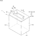
- Fig. 5 is a perspective view showing the removal tool 5.
- Fig. 6 is a view illustrating an example of the use of the removal tool 5. In Fig. 6 , top and side views of the removal tool 5 are shown, and the robot arm 9 or the relay section 2 is not shown as appropriate.
- the removal tool 5 is a member used to remove the electrode substrate 3 attached to the relay section 2.
- the removal tool 5 together with the measuring device 1 constitutes a measuring system.
- the removal tool 5 has the shape of a hollow rectangular parallelepiped, and specifically includes a recovery container 51 and the lid part 53 (removal part).
- the recovery container 51 is a member having a tubular shape with a bottom, and includes a horizontal base plate part 511 having a rectangular shape and four side panel parts 513 provided vertically upright on the four sides that are peripheral edges of the base plate part 511 and coupled to each other.
- the lid part 53 is provided on top of the four side panel parts 513, and has the shape of a rectangular plate.
- the lid part 53 has an opening part 55 provided in the center thereof.
- the opening part 55 forms a through hole extending vertically through the lid part 53.
- the opening part 55 includes a first opening 551 and a second opening 553.
- the first opening 551 is greater than part of the electrode substrate 3 where the protruding parts 47 (engagement parts) are formed on both sides.
- the opening width W551 of the first opening 551 is greater than the width W47 from an end portion of one of the protruding parts 47 to an end portion of the other protruding part 47 in the electrode substrate 3 (with reference to Fig. 6 ). This allows not only the first extension part 43 and the second extension part 45 but also the protruding parts 47 on both sides in the electrode substrate 3 to pass through the first opening 551.
- the second opening 553 is provided so as to be continuous with the first opening 551, and is smaller than part of the electrode substrate 3 where the protruding parts 47 are formed on both sides.
- the second opening 553 is provided on one side of the first opening 551 as seen in the third direction D3.
- the opening width W553 of the second opening 553 (width as measured in the second direction D2) is less than the opening width W551 of the first opening 551, less than the width W47 of the electrode substrate 3, and greater than the width W21 (with reference to Fig. 3 ) of the base section 41 (with reference to Fig. 6 ). This precludes the protruding parts 47 on both sides from passing through the second opening 553.
- the removal tool 5 is fixed, for example, in a predetermined position in an attitude such that the side panel parts 513 are parallel to a vertical direction and the base plate part 511 and the lid part 53 are horizontal.
- the robot arm 9 moves the relay section 2 with the electrode substrate 3 attached thereto to a position where the removal tool 5 is provided.
- the robot arm 9 moves to one side of the first direction D1 (a direction toward the lid part 53), so that part of the electrode substrate 3 which is exposed from the housing 23 of the relay section 2 is inserted into the first opening 551 of the removal tool 5 (insertion step S11).
- this insertion step S11 all of the protruding parts 47 on both sides of the electrode substrate 3 together with the extension parts 43 and 45 are inserted through the inside of the first opening 551 into the back side of the lid part 53 (inside of the recovery container 51).
- the robot arm 9 moves in the third direction D3.
- This movement step S12 causes the protruding parts 47 on both sides of the electrode substrate 3 to be placed under the second opening 553.
- the protruding parts 47 on both sides overlap the second opening 553 in the first direction D1.
- tip portions of the engagement surfaces 471 of the protruding parts 47 as seen in the second direction D2 are opposed to the second opening 553.
- the robot arm 9 moves to the other side of the first direction D1 (a direction away from the lid part 53). This withdraws the electrode substrate 3 from the second opening 553 (withdrawal step S13). In this withdrawal step S13, the electrode substrate 3 and the engagement surfaces 471 of the protruding parts 47 on both sides are caught in (engage) the second opening 553, so that the protruding parts 47 on both sides are urged toward the side opposite the relay section 2. As a result, the electrode substrate 3 is removed from the relay section 2. In other words, the electrode substrate 3 is extracted from the housing 23 of the relay section 2 and collected in the recovery container 51.
- the use of the removal tool 5 for the removal of the electrode substrate 3 facilitates the removal of the electrode substrate 3 to be replaced and facilitates the collection of the removed electrode substrate 3.
- the need for the process of cleaning the electrodes is eliminated by attaching, detaching, and replacing a plurality of electrode substrates 3 according to the circumstances, so that the measurement is made with high efficiency and with high accuracy.
- application to a robot system including the robot arm 9 achieves the measurement with higher efficiency and with higher accuracy.
- the present measuring system is extremely advantageous in application to the robot system because the electrode substrate 3 is attached to and detached from the relay section 2 by a relatively simple linear movement.
- the removal tool 5 is used in an attitude such that the opening part 55 of the lid part 53 opens vertically upwardly.
- the removal tool 5 may be used in a horizontally lying attitude.
- the opening part 55 of the lid part 53 opens in a horizontal direction.
- the robot arm 9 moves in a horizontal direction and in a vertical direction as appropriate, whereby the electrode substrate 3 is removed from the relay section 2.
- Fig. 7 is a top view showing a culture vessel 6 to which the measuring device 1 is applied.
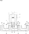
- Fig. 8 is a sectional view of the measuring device 1 applied to the culture vessel 6.
- Fig. 9 is a schematic diagram showing electrical connections of the measuring device 1.
- the culture vessel 6 is a vessel for cultivating cells which are objects whose electrical resistance is to be measured with the electrodes 35 to 38 provided on the electrode substrate 3.
- the culture vessel 6 is what is called a well plate having a plurality of wells 61. As shown in Figs. 7 and 8 , each of the wells 61 is formed in a tubular shape with a bottom. In the culture vessel 6, a total of six wells 61 are arranged in a matrix with two rows arranged in a vertical direction and three columns arranged in a horizontal direction.
- the culture vessel 6 is not limited to that having six wells 61, but may have, for example, 12, 24, 96, or 384 wells.
- the insert cup 63 is placed inside each of the wells 61 of the culture vessel 6.
- the insert cup 63 includes a cylindrical part 631, support parts 633, and a cell culture part 635.
- the cylindrical part 631 is made of an insulative material, and is formed in a frustoconical (tapering toward the cell culture part 635) and tubular shape.
- the support parts 633 are parts extending outwardly from an upper end of the cylindrical part 631.
- the cylindrical part 631 and the cell culture part 635 are placed in a position inside each of the wells 61 where the cell culture part 635 is not in contact with a bottom surface of each of the wells 61.
- the support parts 633 are disposed radially in three locations circumferentially of the one cylindrical part 631.
- the support parts 633 may be of any configuration capable of supporting the cylindrical part 631 and the cell culture part 635 in a predetermined position.
- the support parts 633 may be disposed only in two locations circumferentially of the insert cup 63 or in four or more locations.
- a support part 633 may be provided in the shape of a flange extending outwardly from a circumferential portion of the insert cup 63.
- the cell culture part 635 is a membrane covering a lower opening of the cylindrical part 631.
- a membrane having cell adhesive properties is preferably used for the cell culture part 635.
- a plate-like member provided with a large number of minute through holes is preferably used for the cell culture part 635.
- the extension parts 43 and 45 of the electrode substrate 3 attached to the relay section 2 are placed over one of the wells 61 in the culture vessel 6, for example, by moving the robot arm 9 in a horizontal direction.
- the tips of the extension parts 43 and 45 of the electrode substrate 3 are placed inside the one well 61 by moving the robot arm 9 vertically downwardly (with reference to Fig. 8 ).
- the first extension part 43 is placed inside the insert cup 63
- the second extension part 45 is placed inside the well 61 and outside the insert cup 63.
- the tips of the extension parts 43 and 45 are immersed in the culture solution stored in the well 61 and in the insert cup 63.
- the terminal parts 351, 361, 371, and 381 of the electrodes 35 to 38 provided on the main surfaces of the extension parts 43 and 45 are placed below the level (indicated by a broken line in Fig. 8 ) of the culture solution.
- the terminal parts 351, 361, 371, and 381 are immersed in the culture solution.
- the measuring device 1 includes the power supply 11 and the voltmeter 13.
- the power supply 11 has an output terminal connected through a conducting wire 15 to the first working electrode 35 and the second working electrode 37.
- the voltmeter 13 has an input terminal connected through a conducting wire 17 to the first reference electrode 36 and the second reference electrode 38.
- a resistance Rm corresponds to the electrical resistance of the cell culture part 635 and the cells cultivated on the cell culture part 635 (which are collectively referred to hereinafter as a "cellular part").
- a resistance Rw1 is the electrical resistance of the culture solution between the first working electrode 35 and the cellular part.
- a resistance Rw2 is the electrical resistance of the culture solution between the second working electrode 37 and the cellular part.
- a resistance Rr1 is the electrical resistance of the culture solution between the first reference electrode 36 and the cellular part.
- a resistance Rr2 is the electrical resistance of the culture solution between the second reference electrode 38 and the cellular part.
- the power supply 11 is driven to apply an electric potential between the first working electrode 35 and the second working electrode 37, and the voltmeter 13 measures a voltage value between the first reference electrode 36 and the second reference electrode 38 at the same time. Then, the exact voltage value between the working electrodes 35 and 37 is calculated from the measured voltage value by a computer not shown or by manual calculation, and the electrical resistance between the working electrodes 35 and 37 is calculated from the voltage value. Further, the resistance Rm of the cellular part is calculated from the electrical resistance between the working electrodes 35 and 37 by the computer not shown or by the manual calculation. Thus, the electrical properties of the cells cultivated on the cell culture part 635 are obtained.
- the power supply 11 When the power supply 11 is used to apply an electric potential between the working electrodes 35 and 37, oxidation and reduction reactions of the culture solution occur on the surfaces of the working electrodes 35 and 37, which in turn results in the formation of an electric double layer in some cases.
- an output potential by the power supply 11 and a volage value between the working electrodes 35 and 37 differ from each other.
- the reference electrodes 36 and 38 are disposed in the vicinity of the working electrodes 35 and 37, respectively, and an electric potential between the reference electrodes 36 and 38 is measured. The resistance Rm of the cellular part is measured more accurately by calculation using the measured electric potential.
- the terminal part 351 of the first working electrode 35 is provided on the first main surface 431 of the first extension part 43, and the terminal part 361 of the first reference electrode 36 is provided on the second main surface 432 thereof in the present embodiment.
- the terminal part 371 of the second working electrode 37 provided on the second extension part 45 and the terminal part 381 of the second reference electrode 38 provided thereon are allowed to be in close proximity to each other.
- the resistance Rm of the cellular part is measured accurately.
- the first extension part 43 present between the electrodes 35 and 36 provides electrical insulation between the electrodes 35 and 36.
- the second extension part 45 present between the electrodes 37 and 38 provides electrical insulation between the electrodes 37 and 38.
- the two extension parts 43 and 45 have the same length in the first direction D1 in the electrode substrate 3.
- the second extension part 45 may be made longer than the first extension part 43, for example.
- the tip of the second extension part 45 is brought closer to the bottom surface of the well 61 while the tip of the first extension part 43 is restrained from interfering with the cell culture part 635. This allows the terminal parts 371 and 381 of the electrodes 37 and 38 wired in the second extension part 45 to be disposed in a position close to the bottom surface of the well 61 (e.g., in a position below the cell culture part 635).
- multiple sets of relay sections 2 and electrode substrates 3 may be provided for one set of power supply 11 and voltmeter 13.
- multiple sets of electrodes 35 to 38 may be connected to one power supply 11 or one voltmeter 13.
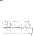
- Fig. 10 is a schematic side view showing a substrate holder 7 which holds a plurality of electrode substrates 3.
- Fig. 11 is a schematic side view of the substrate holder 7 which supports an electrode substrate 3.
- the substrate holder 7 holds the plurality of electrode substrates 3 arranged in a row or in multiple rows and in regularly spaced apart relation in the row direction.
- the substrate holder 7 is formed in the shape of a hollow box, and includes a plate-like ceiling part 71 disposed on a vertically upper side, and a plate-like bottom part 73 disposed on a vertically lower side. Multiple sets of through holes 711 and 713 arranged in predetermined spaced apart relation in one direction are formed in the ceiling part 71.
- the first extension part 43 is inserted into each of the through holes 711, and the second extension part 45 is inserted into each of the through holes 713.
- a distance between the ceiling part 71 and the bottom part 73 is greater than the length of the extension parts 43 and 45 as measured in the first direction D1.
- the substrate holder 7 holds the electrode substrates 3, with the extension parts 43 and 45 of the electrode substrates 3 inserted in the through holes 711 and 713. In this state, the protruding parts 47 on both sides of the electrode substrate 3 are supported by the ceiling part 71, as shown in Fig. 11 . Also, a middle part 415 between the extension parts 43 and 45 in the base section 41 is supported by an upper surface of a middle support part 715 between the through holes 711 and 713 in the ceiling part 71. In this manner, the substrate holder 7 holds the electrode substrates 3, with the extension parts 43 and 45 disposed on a vertically lower side and the connection terminals 33 disposed on a vertically upper side.
- the robot arm 9 For attaching the electrode substrate 3 to the relay section 2, the robot arm 9 causes the relay section 2 to approach one of the electrode substrates 3 held by the substrate holder 7 from immediately over the one electrode substrate 3. Then, by moving the robot arm 9 vertically downwardly, the electrode substrate 3 enters the insertion port 231 of the housing 23, and the electrode substrate 3 is thus fixed to the housing 23. Once the electrode substrate 3 is attached to the relay section 2, the robot arm 9 moves vertically upwardly to withdraw the electrode substrate 3 from the substrate holder 7.
- the substrate holder 7 holds the plurality of electrode substrates 3, whereby each of the electrode substrates 3 is easily attached to the relay section 2. Also, the combined use of the removal tool 5 and the substrate holder 7 facilitates the attachment, removal, and replacement of the electrode substrates 3.
- the through holes 711 and 713 may be coupled to each other to form a single through hole, for example.
- the ceiling part 71 does not support the middle part 415 but supports lower edges of the protruding parts 47 on both sides to support each of the electrode substrates 3 because the middle support part 715 is omitted.
- the ceiling part 71 may be configured to support only the middle part 415 of each of the electrode substrates 3 without supporting the protruding parts 47 on both sides.
- the ceiling part 71 may be formed by only one or more middle support parts 715.
- Fig. 12 is a front view showing an electrode substrate 3a according to a first modification.
- the protruding parts 47 on both sides in the electrode substrate 3a are provided on side portions of the first and second extension parts 43 and 45, whereas the protruding parts 47 on both sides in the electrode substrate 3 of the aforementioned embodiment are provided on the base section 41.
- the removal tool 5 or other removal members may engage the protruding parts 47 on both sides of the electrode substrate 3a in the relay section 2, whereby the electrode substrate 3a is removed from the measuring device 1.
- the use of the electrode substrate 3a produces effects similar to those obtained when the electrode substrate 3 is used.
- Fig. 13 is a front view showing an electrode substrate 3b according to a second modification.
- the electrode substrate 3b includes a second extension part 45a extending from a side edge of the base section 41.
- the second extension part 45a from its base end portion to its tip extends in a direction away from the first extension part 43. Accordingly, a distance between the outsides of the first extension part 43 and the second extension part 45a gradually increases toward one side of the first direction D1.
- the second extension part 45a is provided with the second working electrode 37 and the second reference electrode 38.
- the first extension part 43 of the electrode substrate 3b is provided with a protruding part 47.
- the electrode substrate 3b is easily attached to and removed from the housing 23 of the relay section 2.
- the extension parts 43 and 45a are initially inserted through the inside of the first opening 551 of the opening part 55, and are then moved toward the second opening 553 side. Then, the electrode substrate 3 is moved upwardly, whereby the protruding part 47 provided on the first extension part 43 and an outer surface 453 (a surface on the side opposite the first extension part 43) of the second extension part 45a engage the lower surface of the second opening 553.
- the outer surface 453 of the second extension part 45a functions as an engagement surface in this modification to achieve the removal of the electrode substrate 3b from the relay section 2.
- the outer surface 453 functions as the engagement surface or the engagement part.
- first extension part 43 may extend in a direction away from the second extension part 45a toward one side of the first direction D1.
- the protruding part 47 may be dispensed with if the outer surface of the first extension part 43 is capable of functioning as the engagement surface.
- Fig. 14 is a front view showing an electrode substrate 3c according to a third modification.
- the protruding parts 47 are provided on both sides of the base section 41.
- recessed parts 47a are provided one in each side edge on each side of the base section 41 as seen in the second direction D2.
- the recessed parts 47a on both sides are provided in the same position with respect to the first direction D1.
- the width Wla between the innermost portions of the recessed parts 47a on both sides is less than the width W1b of the base section 41.
- the direction of the normal to a surface 471a on one side of the first direction D1 from the most recessed portion in the second direction D2 among the inner surfaces of each of the recessed parts 47a has a component of a direction toward the connection terminals 33 side (the other side of the first direction D1).
- the surface 471a in each of the recessed parts 47a functions as an engagement surface.
- the opening width W553 of the second opening 553 of the opening part 55 in the removal tool 5 is required only to be greater than the width W1a and less than the width Wlb. This allows the second opening 553 to enter the inside of the recessed parts 47a on both sides.
- the surfaces 471a of the recessed parts 47a on both sides engage the second opening 553 by withdrawing the electrode substrate 3c from the second opening 553, with the second opening 553 entering the inside. This facilitates the removal of the electrode substrate 3c attached to the relay section 2 from the relay section 2.
- the recessed parts 47a may be provided in the extension parts 43 and 45.
- the two electrodes 35 and 36 are provided on the common first extension part.
- a third extension part extending from the base section 41 may be provided in the vicinity of the first extension part 43, so that one of the electrodes 35 and 36 is provided on the first extension part 43 and the other is provided on the third extension part.
- a fourth extension part extending from the base section 41 may be provided in the vicinity of the second extension part 45, so that one of the electrodes 37 and 38 is provided on the second extension part 45 and the other is provided on the fourth extension part.
- the terminal part 361 of the first reference electrode 36 may be provided on the first main surface 431 of the first extension part 43.
- the terminal part 381 of the second reference electrode 38 may be provided on the first main surface 451 of the second extension part 45.
- the terminal part 351 of the first working electrode 35 may be provided on the second main surface 432 of the first extension part 43.
- a through hole may be provided in the base section 41 in the same manner as the through hole 413a, so that the first working electrode 35 is wired through the through hole on the second main surface 312 of the substrate 31.
- the terminal part 371 of the second working electrode 37 may be provided on the second main surface 452 of the second extension part 45.
- each of the extension parts 43 and 45 is shaped to extend in a straight line in the aforementioned embodiment, the extension parts may have a bent or curved shape.
- the electrodes 35 to 38 may be bent or curved in accordance with the bent or curved shape of the extension parts.
- the extension parts 43 and 45 are shaped to extend outwardly from one side edge portion of the base section 41 as seen in the first direction D1.
- the extension parts may be shaped to extend outwardly from any one of the side edge portions of the base section 41 as seen in the second direction D2.
- the extension parts 43 and 45 may extend in the third direction D3.
- the number and position of contact parts 25 inside the housing 23 may be provided in conformity with other SD standards.
- the mounting position of the connection terminals 33 in the electrode substrate 3 or the shape of the substrate 31 may be changed in accordance with the selected standard.
- the contact parts 25 may be configured not to be in conformity with standards.
Landscapes
- Health & Medical Sciences (AREA)
- Life Sciences & Earth Sciences (AREA)
- Chemical & Material Sciences (AREA)
- Engineering & Computer Science (AREA)
- Physics & Mathematics (AREA)
- Biomedical Technology (AREA)
- Analytical Chemistry (AREA)
- Biochemistry (AREA)
- General Health & Medical Sciences (AREA)
- General Physics & Mathematics (AREA)
- Immunology (AREA)
- Pathology (AREA)
- Molecular Biology (AREA)
- Electrochemistry (AREA)
- Chemical Kinetics & Catalysis (AREA)
- Biophysics (AREA)
- Hematology (AREA)
- Urology & Nephrology (AREA)
- Food Science & Technology (AREA)
- Medicinal Chemistry (AREA)
- Optics & Photonics (AREA)
- Wood Science & Technology (AREA)
- Organic Chemistry (AREA)
- Bioinformatics & Cheminformatics (AREA)
- Zoology (AREA)
- Microbiology (AREA)
- Sustainable Development (AREA)
- Biotechnology (AREA)
- General Engineering & Computer Science (AREA)
- Genetics & Genomics (AREA)
- Cell Biology (AREA)
- Investigating Or Analyzing Materials By The Use Of Electric Means (AREA)
- Apparatus Associated With Microorganisms And Enzymes (AREA)
- Measuring Or Testing Involving Enzymes Or Micro-Organisms (AREA)
Abstract
Description
- The present invention relates to a technique for measuring the electrical resistance of biological cells or tissues.
- There has been known a technique for measuring the electrical resistance of biological cells or tissues for purposes of investigating the property or state of the cells or tissues. For example, in transepithelial electrical resistance (TEER) measurement, electrodes are disposed on one side and the other side of a membrane for cell culture in a culture solution to measure electrical resistance, thereby measuring the electrical resistance of the cells themselves cultured in the form of the membrane.
-
Patent Literature 1 discloses a technique for measuring the electrical resistance of cells by immersing elongated chopstick-shaped electrodes in a culture solution.Patent Literature 2 discloses a technique for measuring electrical resistance while maintaining a culture environment, with electrodes provided in a lid part of a culture vessel and inside the vessel. -
- Patent Literature 1:
Japanese Patent Application Laid-Open No. 2005-137307 - Patent Literature 2:
Japanese Patent Application Laid-Open No. 2009-27928 - It is known that when precipitates generated in a culture solution adhere to the electrodes during the measurement of electrical resistance, the measurement results become unstable. In the case of
Patent Literature 2, for example, there is a danger that the electrodes are contaminated due to prolonged measurement, which in turn results in a danger that accurate measurement is difficult. In the case ofPatent Literature 1, the technique requires complicated operations such as cleaning the electrodes each time the electrodes are contaminated. - It is therefore an object of the present invention to provide a technique for measuring the electrical resistance of cells or tissues with high efficiency and with high accuracy.
- To solve the aforementioned problem, a first aspect of the present invention is intended for an electrode substrate having electrodes for measuring an electrical resistance of biological cells or tissues. The electrode substrate comprises: a substrate having a base section, a first extension part extending from the base section, and a second extension part extending from the base section; a plurality of connection terminals provided on a surface of the base section; a first working electrode and a second working electrode each connected to one of the connection terminals, the first and second working electrodes being wired on a surface of the substrate; and an engagement surface provided on the substrate and facing toward the connection terminals in a position closer to the first extension part than the connection terminals, the first working electrode being wired from the base section to the first extension part, the second working electrode being wired from the base section to the second extension part.
- A second aspect of the present invention is intended for the electrode substrate of the first aspect, wherein the engagement surface is provided on an engagement part provided on a side edge of the substrate and having a protruding or recessed shape.
- A third aspect of the present invention is intended for the electrode substrate of the second aspect, wherein the engagement part is provided in the base section.
- A fourth aspect of the present invention is intended for the electrode substrate of the second or third aspect, wherein the first extension part extends in a first direction from a side edge of the base section, and wherein the engagement part has a shape protruding or recessed in a second direction orthogonal to the first direction.
- A fifth aspect of the present invention is intended for the electrode substrate of the fourth aspect, which further comprises a first reference electrode and a second reference electrode each connected to one of the connection terminals, the first and second reference electrodes being wired on the surface of the substrate.
- A sixth aspect of the present invention is intended for the electrode substrate of the fifth aspect, wherein the first reference electrode is wired from the base section to the first extension part.
- A seventh aspect of the present invention is intended for the electrode substrate of the sixth aspect, wherein the first working electrode is wired on one main surface of the first extension part, and wherein the first reference electrode is wired on the other main surface of the first extension part.
- An eighth aspect of the present invention is intended for the electrode substrate of any one of the fifth to seventh aspects, wherein the base section has a through hole, and wherein one of the first working electrode and the first reference electrode is wired from one main surface of the base section through the through hole onto the other main surface of the base section.
- A ninth aspect of the present invention is intended for a measuring device for measuring an electrical resistance of biological cells or tissues. The measuring device comprises: an electrode substrate having electrodes; and a relay section to which the electrode substrate is to be removably attached, wherein the electrode substrate includes a substrate having a base section, a first extension part extending from the base section, and a second extension part extending from the base section, a plurality of connection terminals provided on a surface of the base section, a first working electrode and a second working electrode each connected to one of the connection terminals, the first and second working electrodes being wired on a surface of the substrate, and an engagement surface provided on the substrate and facing toward the connection terminals in a position closer to the first extension part than the connection terminals, the first working electrode being wired from the base section to the first extension part, the second working electrode being wired from the base section to the second extension part, and wherein the relay section includes a plurality of contact parts for contact with the respective connection terminals.
- A tenth aspect of the present invention is intended for the measuring device of the ninth aspect, wherein the relay section further includes an insertion port for insertion of the base section of the electrode substrate therein, and wherein the contact parts are provided inside the insertion port.
- An eleventh aspect of the present invention is intended for the measuring device of the tenth aspect, wherein the engagement surface of the electrode substrate is exposed to the outside of the insertion port, with the base section of the electrode substrate inserted in the insertion port of the relay section.
- A twelfth aspect of the present invention is intended for the measuring device of any one of the ninth to eleventh aspects, wherein the contact parts provided in the relay section are provided in conformity with an SD standard.
- A thirteenth aspect of the present invention is intended for a removal tool for removing the electrode substrate from the relay section in a measuring device as recited in any one of the ninth to twelfth aspects. The removal tool comprises a removal part provided with an opening part for insertion of the electrode substrate therein, wherein the opening part includes a first opening greater than part of the electrode substrate where the engagement surface is provided, and a second opening continuous with the first opening and smaller than the part of the electrode substrate where the engagement surface is provided.
- A fourteenth aspect of the present invention is intended for a measuring method for measuring an electrical resistance of biological cells or tissues by means of a measuring system, the measuring system including an electrode substrate, a relay section to which the electrode substrate is to be attached, and a removal tool for removing the electrode substrate from the relay section, the electrode substrate including a substrate having a base section, a first extension part extending from the base section, and a second extension part extending from the base section, a plurality of connection terminals provided on a surface of the base section, a first working electrode and a second working electrode each connected to one of the connection terminals, the first and second working electrodes being wired on a surface of the substrate, and an engagement surface provided on the substrate and facing toward the connection terminals in a position closer to the first extension part than the connection terminals, the removal tool including a removal part provided with an opening part for insertion of the electrode substrate therein, the opening part including a first opening greater than part of the electrode substrate where the engagement surface is provided, and a second opening continuous with the first opening and smaller than the part of the electrode substrate where the engagement surface is provided. The method comprises the steps of:
- a) inserting the part of the electrode substrate where the engagement surface is provided into the first opening, with the electrode substrate attached to the relay section; b) moving the electrode substrate to the inside of the second opening, the step b) being performed after the step a); and c) withdrawing the electrode substrate from the second opening to bring the second opening into engagement with the engagement surface, the step c) being performed after the step b).
- According to the first aspect, the first working electrode and the second working electrode are electrically connected through the connection terminals of the electrode substrate to the relay section of the measuring device. Thus, the replacement of the electrodes is achieved by the replacement of the electrode substrate. Also, the provision of the engagement surface facing toward the connection terminals side on the electrode substrate allows the engagement part to be urged in a direction opposite the connection terminals while the removal tool is in engagement with the engagement surface. This facilitates the removal of the electrode substrate connected to the relay section. Therefore, the electrical resistance of the cells or tissues is measured with high efficiency and with high accuracy because the replacement of the electrodes is facilitated.
- According to the second aspect, the removal of the electrode substrate from the relay section is facilitated by bringing the removal tool into engagement with the engagement part having the protruding or recessed shape.
- According to the third aspect, when the engagement part is provided in the base section, the deformation of the substrate is reduced if the removal tool is in engagement with the engagement surface and a force is applied thereto.
- According to the fourth aspect, the electrode substrate is urged in the first direction by bringing the removal tool into engagement with the engagement part. This allows the electrode substrate to be removed from the relay section in the first direction.
- According to the fifth aspect, the electric potential applied to the cells or tissues is measured between the first reference electrode and the second reference electrode. Since the electric potential applied between the first reference electrode and the second working electrode is determined from this measurement value, the electrical resistance of the cells or tissues is measure more accurately.
- According to the sixth aspect, the electrode substrate is reduced in size because the first working electrode and the first reference electrode are provided on the common first extension part.
- According to the seventh aspect, the electrodes are placed on the main surfaces on both sides of the first extension part, whereby regions of the respective main surfaces are effectively used. Also, the first working electrode and the first reference electrode are insulated by the first extension part. In addition, the first working electrode and the first reference electrode are disposed close to each other.
- According to the eighth aspect, the electrodes are wired on the main surfaces on both sides of the base section, whereby regions of the respective main surfaces are effectively used.
- According to the ninth aspect, the electrode substrate, which includes the plurality of connection terminals, is attachable to and removable from the relay section, so that the replacement of the electrodes is facilitated. Also, the provision of the engagement surface facing toward the connection terminals on the electrode substrate allows the electrode substrate to be urged in a direction opposite the connection terminals while the removal tool is in engagement with the engagement surface. This facilitates the removal of the electrode substrate connected to the relay section through the connection terminals. Therefore, the electrical resistance of the cells or tissues is measured with high efficiency and with high accuracy because the replacement of the electrodes is achieved by the replacement of the electrode substrate.
- According to the tenth aspect, the connection terminals provided on the electrode substrate are brought into contact with the contact parts of the relay section by inserting the electrode substrate into the insertion port of the relay section. This facilitates the attachment of the electrode substrate to the relay section.
- According to the eleventh aspect, the removal tool is brought into engagement with the engagement surface of the electrode substrate inserted into the insertion port of the relay section because the engagement surface is exposed to the outside of the insertion port.
- According to the twelfth aspect, an adapter in conformity with SD standards can be used for the relay section. This reduces the manufacturing costs of the measuring device.
- According to the thirteenth aspect, part of the engagement surface of the electrode substrate is inserted into the first opening. Thereafter, the electrode substrate is moved to the inside of the second opening, and is then withdrawn. Thus, the engagement surface is brought into engagement with the removal part. This allows the removal of the electrode substrate from the relay section.
- According to the fourteenth aspect, the part of the electrode substrate where the engagement surface is provided is inserted into the first opening. Thereafter, the electrode substrate is moved to the second opening, and is then withdrawn. Thus, the second opening is brought into engagement with the engagement surface. This facilitates the removal of the electrode substrate connected to the relay section. Therefore, the electrical resistance of the cells or tissues is measured with high efficiency and with high accuracy because the replacement of the electrodes is facilitated.
-
- [
fig. 1] Fig. 1 is a view showing a measuring device. - [
fig. 2] Fig. 2 is a view showing a relay section. - [
fig. 3] Fig. 3 is a plan view showing an electrode substrate. - [
fig. 4] Fig. 4 is a plan view showing the electrode substrate. - [
fig. 5] Fig. 5 is a perspective view showing a removal tool. - [
fig. 6] Fig. 6 is a view illustrating an example of the use of the removal tool. - [
fig. 7] Fig. 7 is a top view showing a culture vessel to which the measuring device is applied. - [
fig. 8] Fig. 8 is a sectional view of the measuring device applied to the culture vessel. - [
fig. 9] Fig. 9 is a schematic diagram showing electrical connections of the measuring device. - [
fig. 10] Fig. 10 is a schematic side view showing a substrate holder which holds a plurality of electrode substrates. - [
fig. 11] Fig. 11 is a schematic sectional view showing the substrate holder which supports an electrode substrate. - [
fig. 12] Fig. 12 is a front view showing an electrode substrate according to a first modification. - [
fig. 13] Fig. 13 is a front view showing an electrode substrate according to a second modification. - [
fig. 14] Fig. 14 is a front view showing an electrode substrate according to a third modification. - An embodiment according to the present invention will now be described with reference to the drawings. Components described in the embodiment are merely illustrative, and there is no intention to limit the scope of the present invention thereto. In the drawings, the dimensions of components and the number of components are shown in exaggeration or in simplified form, as appropriate, for the sake of easier understanding in some cases. Unless otherwise specified, the expression "extending in a specific direction" includes not only "extending parallel to a specific direction" but also "extending in a direction obtained by combining a specific direction and a direction perpendicular to the specific direction".
-
Fig. 1 is a view showing ameasuring device 1. The measuringdevice 1 has a configuration suitable for measuring the electrical resistance of biological cells or tissues. Specifically, the measuringdevice 1 includes arelay section 2 and anelectrode substrate 3. Therelay section 2 is fixed to arobot arm 9 by a fixing method such as screwing. Therobot arm 9 moves in three-dimensional space in accordance with the driving force of a motor (driving part) that operates under the control of a computer not shown. Theelectrode substrate 3 is attached to therelay section 2. In this embodiment, theelectrode substrate 3 is removably attached to therelay section 2 by being inserted into aninsertion port 231 of ahousing 23 provided in therelay section 2. - In the following description, a longitudinal direction of the
electrode substrate 3 which is parallel to a main surface (a firstmain surface 411 of abase section 41 to be described later) is referred to as a first direction D1, and a direction parallel to the main surface of theelectrode substrate 3 and orthogonal to the first direction D1 is referred to as a second direction D2, based on a condition where theelectrode substrate 3 is attached to therelay section 2, as shown inFig. 1 . Also, a direction orthogonal to both the first direction D1 and the second direction D2 (the thickness direction of thebase section 41 in the electrode substrate 3) is referred as a third direction D3 (with reference toFig. 6 ). -
Fig. 2 is a view showing therelay section 2. Therelay section 2 includes arelay board 21 and thehousing 23. Therelay board 21 is a flat plate member made of an insulative material such as epoxy resin or glass epoxy resin. Thehousing 23 is provided on an end portion of onemain surface 211 of therelay board 21 on one side as seen in the first direction D1 and in the middle thereof as seen in the second direction D2. Thehousing 23 includes theinsertion port 231 that opens toward the one side as seen in the first direction D1. Thehousing 23 has an interior (i.e., inside of the insertion port 231) sized to accommodate thebase section 41 of theelectrode substrate 3. Inside thehousing 23, a plurality of (in this embodiment, eight)contact parts 25 are mounted in an array along the second direction D2. Thecontact parts 25 are connected to acable 27. Thecable 27 is connected to a device for measuring electrical resistance, such as apower supply 11 or a voltmeter 13 (with reference toFig. 9 ). - The number and position of
contact parts 25 inside thehousing 23 coincide with the number (eight) and position of contact parts provided in an adapter in conformity with Micro SD standards, for example. In this case, a board for a card reader in conformity with the Micro SD standards can be used for therelay board 21. This reduces the production costs of therelay section 2. -
Fig. 3 is a plan view showing theelectrode substrate 3.Fig. 4 is a plan view showing theelectrode substrate 3.Fig. 3 is a view showing a firstmain surface 311 side of asubstrate 31, andFig. 4 is a view showing a secondmain surface 312 side opposite the firstmain surface 311 of thesubstrate 31. - The
electrode substrate 3 includes thesubstrate 31, a plurality ofconnection terminals 33, a first workingelectrode 35, afirst reference electrode 36, a second workingelectrode 37, and asecond reference electrode 38. The first workingelectrode 35, thefirst reference electrode 36, the second workingelectrode 37, and thesecond reference electrode 38 are generically referred to as "electrodes 35 to 38" in some cases in the following description. - The
substrate 31 is a rigid, flat plate member made of an insulative material such as epoxy resin or glass epoxy resin. Thesubstrate 31 includes thebase section 41, afirst extension part 43, asecond extension part 45, and two protrudingparts 47. Thebase section 41, thefirst extension part 43, thesecond extension part 45, and the two protrudingparts 47 are formed integrally and have the same thickness. However, some or all of these parts may be members provided independently of other elements. As shown inFig. 1 , thefirst extension part 43, thesecond extension part 45, and the two protrudingparts 47 are exposed to the outside of thehousing 23, with theelectrode substrate 3 attached to therelay section 2. - The
substrate 31 has the firstmain surface 311 and the secondmain surface 312 on the side opposite the firstmain surface 311. The term "main surfaces" used herein refer to surfaces having the largest area. The firstmain surface 311 of thesubstrate 31 includes the firstmain surface 411 of thebase section 41, a first main surface 431 (one main surface) of thefirst extension part 43, and a firstmain surface 451 of thesecond extension part 45. The secondmain surface 312 of thesubstrate 31 includes a secondmain surface 412 of thebase section 41, a second main surface 432 (the other main surface) of thefirst extension part 43, and a secondmain surface 452 of thesecond extension part 45. - The outer shape of the
base section 41 as seen in plan view is similar to that of a typical Micro SD card. For example, a lockingpart 410 having an uneven shape similar to that of a Micro SD card is provided on one side of thebase section 41 as seen in the second direction D2. When thebase section 41 of theelectrode substrate 3 is inserted into thehousing 23 of therelay section 2, an L-shapedplate spring 233 provided on one side in thehousing 23 engages a recessed portion of the lockingpart 410 of the base section 41 (with reference toFig. 1 ). This fixes theelectrode substrate 3 in a fixed position relative to therelay section 2, with the electrodes of theelectrode substrate 3 in contact with therespective contact parts 25 of therelay section 2. A spring mechanism or the like for urging theelectrode substrate 3 toward one side of the first direction D1 may be provided inside thehousing 23. - Two through
holes base section 41 as seen in the first direction D1 and the second direction D2. In this embodiment, the throughholes electrode 35 and a wiring part of the second workingelectrode 37. A wiring part of thefirst reference electrode 36 is provided in the throughhole 413a, and a wiring part of thesecond reference electrode 38 is provided in the throughhole 413b. - The
first extension part 43 and thesecond extension part 45 are plate-like parts extending outwardly from different portions at a side edge of thebase section 41. The term "side edge" used herein refers to a peripheral edge portion sandwiched between the outer peripheral portions of the firstmain surface 411 and the secondmain surface 412 of thebase section 41. Base end portions of therespective extension parts base section 41 on one side as seen in the first direction D1, and theextension parts extension parts first extension part 43 as measured in the second direction D2 and the width W12 of thesecond extension part 45 as measured in the second direction D2 are less than the width W21 of thebase section 41 as measured in the second direction D2. Although the shape and size of thefirst extension part 43 are the same as those of thesecond extension part 45 in this embodiment, the shape or size of thefirst extension part 43 may be different from that of thesecond extension part 45. - One protruding
part 47 is provided on each side of thebase section 41 in the second direction D2. The protrudingparts 47 on both sides are provided in the same position with respect to the first direction D1. The protrudingparts 47 are parts of thebase section 41 which protrude in the second direction D2 from other parts (e.g., parts inserted in the housing 23). The width W1 (with reference toFigs. 1 and3 ) between the tips of the protrudingparts 47 as measured in the second direction D2 is greater than the width W2 (with reference toFigs. 1 and2 ) of theinsertion port 231 of thehousing 23 as measured in the second direction D2. The width of theelectrode substrate 3 is the largest in portions where the protrudingparts 47 are provided on both sides. In other words, the width W1 is the largest width in theelectrode substrate 3. - The protruding
parts 47 provided on both sides of thebase section 41 are used for the removal of theelectrode substrate 3 attached to therelay section 2. Each of the protrudingparts 47 has anengagement surface 471 facing toward theconnection terminals 33 side (the other side of the first direction). The expression "the engagement surface faces toward the connection terminals" means that the direction of the normal to the engagement surface is parallel to a terminal side direction toward the connection terminals or is a direction having at least a component of the terminal side direction (i.e., a direction not perpendicular to the terminal side direction). The engagement surfaces 471 engage a lid part 53 (removal part) of aremoval tool 5, so that the protrudingparts 47 are urged toward the side opposite the connection terminals 33 (one side of the first direction D1). This urging force allows the electrode substrate to be removed from therelay section 2. - The plurality of (in this embodiment, eight)
connection terminals 33 are provided on the firstmain surface 311 of thebase section 41. Terminal parts of theelectrodes 35 to 38 are connected to theconnection terminals 33. In this embodiment, each of theelectrodes 35 to 38 is connected to adjacent two of theconnection terminals 33. For example, the first workingelectrode 35 is connected to adjacent two of theconnection terminals 33, and has wiring parts meeting in an intermediate position in thebase section 41. In other words, the first workingelectrode 35 branches from one wiring part into two wiring parts in thebase section 41, and each of the two wiring parts is connected to one of the twoadjacent connection terminals 33. In this case, if a conduction anomaly occurs in one of the twoconnection terminals 33 due to adhesion of foreign materials or the like but conduction is ensured in theother connection terminal 33, conduction between the first workingelectrode 35 and therelay section 2 is ensured. Similar effects are produced in each of theother electrodes connection terminals 33. - The
electrodes 35 to 38 are wired on the surface of thesubstrate 31. The wiring for theelectrodes 35 to 38 are provided on the surface of thesubstrate 31 by various methods such as etching and direct drawing, for example. In this example, theelectrodes 35 to 38 are arranged in the order named along the second direction D2. However, the order of arrangement of theelectrodes 35 to 38 is not limited to this but may be changed as appropriate. - The first working
electrode 35 is wired from thebase section 41 to thefirst extension part 43, and is provided on the firstmain surface 311 side of the substrate 31 (with reference toFig. 3 ). Specifically, the first workingelectrode 35 is provided on the firstmain surface 411 of thebase section 41 and on the firstmain surface 431 of thefirst extension part 43. - The
first reference electrode 36 is wired from thebase section 41 to the first extension part 43 (with reference toFig. 4 ). Specifically, the wiring part extending from the twoconnection terminals 33 to the throughhole 413a is provided on the firstmain surface 311 side of thesubstrate 31, and the wiring part beyond the throughhole 413a is provided on the secondmain surface 312 side of thesubstrate 31. That is, thefirst reference electrode 36 is wired on the secondmain surface 432 of thefirst extension part 43. - The second working
electrode 37 is wired from thebase section 41 to thesecond extension part 45, and is provided on the firstmain surface 311 side of the substrate 31 (with reference toFig. 3 ). Specifically, the second workingelectrode 37 is provided on the firstmain surface 411 of thebase section 41 and on the firstmain surface 451 of thesecond extension part 45. - The
second reference electrode 38 is wired from thebase section 41 to the second extension part 45 (with reference toFig. 4 ). Specifically, the wiring part extending from the twoconnection terminals 33 to the throughhole 413b is provided on the firstmain surface 311 side of thesubstrate 31, and the wiring part beyond the throughhole 413b is provided on the secondmain surface 312 side of thesubstrate 31. That is, thesecond reference electrode 38 is wired on the secondmain surface 452 of thesecond extension part 45. - The wiring parts of the
electrodes 35 to 38 are covered with a resist 49 that is an insulator, andterminal parts first extension part 43 and thesecond extension part 45 are exposed to the outside. Theterminal parts first extension part 43 and the tip of thesecond extension part 45 are spaced apart in the second direction D2. For this reason, theterminal part 351 of the first workingelectrode electrode 37 are disposed in positions separated in the second direction D2 (with reference toFig. 3 ). Also, theterminal parts reference electrodes Fig. 4 ). - In the
electrode substrate 3, the twoelectrodes first extension part 43, whereby theelectrode substrate 3 is reduced in size. Similarly, the twoelectrodes second extension part 45, whereby theelectrode substrate 3 is reduced in size. In addition, theelectrodes main surfaces first extension part 43, whereby the region of themain surfaces electrodes main surfaces second extension part 45. -
Fig. 5 is a perspective view showing theremoval tool 5.Fig. 6 is a view illustrating an example of the use of theremoval tool 5. InFig. 6 , top and side views of theremoval tool 5 are shown, and therobot arm 9 or therelay section 2 is not shown as appropriate. Theremoval tool 5 is a member used to remove theelectrode substrate 3 attached to therelay section 2. Theremoval tool 5 together with the measuringdevice 1 constitutes a measuring system. Theremoval tool 5 has the shape of a hollow rectangular parallelepiped, and specifically includes arecovery container 51 and the lid part 53 (removal part). Therecovery container 51 is a member having a tubular shape with a bottom, and includes a horizontalbase plate part 511 having a rectangular shape and fourside panel parts 513 provided vertically upright on the four sides that are peripheral edges of thebase plate part 511 and coupled to each other. Thelid part 53 is provided on top of the fourside panel parts 513, and has the shape of a rectangular plate. Thelid part 53 has anopening part 55 provided in the center thereof. The openingpart 55 forms a through hole extending vertically through thelid part 53. - The opening
part 55 includes afirst opening 551 and asecond opening 553. Thefirst opening 551 is greater than part of theelectrode substrate 3 where the protruding parts 47 (engagement parts) are formed on both sides. In this embodiment, the opening width W551 of the first opening 551 (width as measured in the second direction D2) is greater than the width W47 from an end portion of one of the protrudingparts 47 to an end portion of the other protrudingpart 47 in the electrode substrate 3 (with reference toFig. 6 ). This allows not only thefirst extension part 43 and thesecond extension part 45 but also the protrudingparts 47 on both sides in theelectrode substrate 3 to pass through thefirst opening 551. - The
second opening 553 is provided so as to be continuous with thefirst opening 551, and is smaller than part of theelectrode substrate 3 where the protrudingparts 47 are formed on both sides. In this embodiment, thesecond opening 553 is provided on one side of thefirst opening 551 as seen in the third direction D3. The opening width W553 of the second opening 553 (width as measured in the second direction D2) is less than the opening width W551 of thefirst opening 551, less than the width W47 of theelectrode substrate 3, and greater than the width W21 (with reference toFig. 3 ) of the base section 41 (with reference toFig. 6 ). This precludes the protrudingparts 47 on both sides from passing through thesecond opening 553. - With reference to
Fig. 6 , a procedure for the removal of theelectrode substrate 3 from therelay section 2 by means of theremoval tool 5 will be described. Theremoval tool 5 is fixed, for example, in a predetermined position in an attitude such that theside panel parts 513 are parallel to a vertical direction and thebase plate part 511 and thelid part 53 are horizontal. Therobot arm 9 moves therelay section 2 with theelectrode substrate 3 attached thereto to a position where theremoval tool 5 is provided. Then, as shown inFig. 6 , therobot arm 9 moves to one side of the first direction D1 (a direction toward the lid part 53), so that part of theelectrode substrate 3 which is exposed from thehousing 23 of therelay section 2 is inserted into thefirst opening 551 of the removal tool 5 (insertion step S11). In this insertion step S11, all of the protrudingparts 47 on both sides of theelectrode substrate 3 together with theextension parts first opening 551 into the back side of the lid part 53 (inside of the recovery container 51). - After the insertion step S11, the
robot arm 9 moves in the third direction D3. This moves theelectrode substrate 3 from the inside of thefirst opening 551 to the inside of the second opening 553 (movement step S12). This movement step S12 causes the protrudingparts 47 on both sides of theelectrode substrate 3 to be placed under thesecond opening 553. Thus, the protrudingparts 47 on both sides overlap thesecond opening 553 in the first direction D1. In other words, tip portions of the engagement surfaces 471 of the protrudingparts 47 as seen in the second direction D2 are opposed to thesecond opening 553. - After the movement step S12, the
robot arm 9 moves to the other side of the first direction D1 (a direction away from the lid part 53). This withdraws theelectrode substrate 3 from the second opening 553 (withdrawal step S13). In this withdrawal step S13, theelectrode substrate 3 and the engagement surfaces 471 of the protrudingparts 47 on both sides are caught in (engage) thesecond opening 553, so that the protrudingparts 47 on both sides are urged toward the side opposite therelay section 2. As a result, theelectrode substrate 3 is removed from therelay section 2. In other words, theelectrode substrate 3 is extracted from thehousing 23 of therelay section 2 and collected in therecovery container 51. In this manner, the use of theremoval tool 5 for the removal of theelectrode substrate 3 facilitates the removal of theelectrode substrate 3 to be replaced and facilitates the collection of the removedelectrode substrate 3. Thus, for example, even in the case of measurement of multiple samples or measurement of the same sample for a long time, the need for the process of cleaning the electrodes is eliminated by attaching, detaching, and replacing a plurality ofelectrode substrates 3 according to the circumstances, so that the measurement is made with high efficiency and with high accuracy. Also, application to a robot system including therobot arm 9 achieves the measurement with higher efficiency and with higher accuracy. In particular, the present measuring system is extremely advantageous in application to the robot system because theelectrode substrate 3 is attached to and detached from therelay section 2 by a relatively simple linear movement. - The
removal tool 5 is used in an attitude such that theopening part 55 of thelid part 53 opens vertically upwardly. However, theremoval tool 5 may be used in a horizontally lying attitude. In this case, the openingpart 55 of thelid part 53 opens in a horizontal direction. Thus, therobot arm 9 moves in a horizontal direction and in a vertical direction as appropriate, whereby theelectrode substrate 3 is removed from therelay section 2. -
Fig. 7 is a top view showing aculture vessel 6 to which themeasuring device 1 is applied.Fig. 8 is a sectional view of the measuringdevice 1 applied to theculture vessel 6.Fig. 9 is a schematic diagram showing electrical connections of the measuringdevice 1. - The
culture vessel 6 is a vessel for cultivating cells which are objects whose electrical resistance is to be measured with theelectrodes 35 to 38 provided on theelectrode substrate 3. Theculture vessel 6 is what is called a well plate having a plurality ofwells 61. As shown inFigs. 7 and8 , each of thewells 61 is formed in a tubular shape with a bottom. In theculture vessel 6, a total of sixwells 61 are arranged in a matrix with two rows arranged in a vertical direction and three columns arranged in a horizontal direction. Theculture vessel 6 is not limited to that having sixwells 61, but may have, for example, 12, 24, 96, or 384 wells. - An
insert cup 63 is placed inside each of thewells 61 of theculture vessel 6. Theinsert cup 63 includes acylindrical part 631,support parts 633, and acell culture part 635. Thecylindrical part 631 is made of an insulative material, and is formed in a frustoconical (tapering toward the cell culture part 635) and tubular shape. - The
support parts 633 are parts extending outwardly from an upper end of thecylindrical part 631. When thesupport parts 633 are placed on an upper surface of theculture vessel 6, thecylindrical part 631 and thecell culture part 635 are placed in a position inside each of thewells 61 where thecell culture part 635 is not in contact with a bottom surface of each of thewells 61. In this embodiment, thesupport parts 633 are disposed radially in three locations circumferentially of the onecylindrical part 631. It should be noted that thesupport parts 633 may be of any configuration capable of supporting thecylindrical part 631 and thecell culture part 635 in a predetermined position. For example, thesupport parts 633 may be disposed only in two locations circumferentially of theinsert cup 63 or in four or more locations. In place of thesupport parts 633, asupport part 633 may be provided in the shape of a flange extending outwardly from a circumferential portion of theinsert cup 63. - The
cell culture part 635 is a membrane covering a lower opening of thecylindrical part 631. A membrane having cell adhesive properties is preferably used for thecell culture part 635. A plate-like member provided with a large number of minute through holes is preferably used for thecell culture part 635. During the cultivation of cells to be measured, a culture solution is poured into each of thewells 61 at least to a level where thecell culture part 635 is immersed therein. - When the measuring
device 1 is applied to such aculture vessel 6, theextension parts electrode substrate 3 attached to therelay section 2 are placed over one of thewells 61 in theculture vessel 6, for example, by moving therobot arm 9 in a horizontal direction. - Subsequently, the tips of the
extension parts electrode substrate 3 are placed inside the one well 61 by moving therobot arm 9 vertically downwardly (with reference toFig. 8 ). Specifically, thefirst extension part 43 is placed inside theinsert cup 63, and thesecond extension part 45 is placed inside the well 61 and outside theinsert cup 63. Then, the tips of theextension parts insert cup 63. Specifically, theterminal parts electrodes 35 to 38 provided on the main surfaces of theextension parts Fig. 8 ) of the culture solution. Thus, theterminal parts - As shown in
Fig. 9 , the measuringdevice 1 includes thepower supply 11 and thevoltmeter 13. Thepower supply 11 has an output terminal connected through aconducting wire 15 to the first workingelectrode 35 and the second workingelectrode 37. Thevoltmeter 13 has an input terminal connected through aconducting wire 17 to thefirst reference electrode 36 and thesecond reference electrode 38. - In
Fig. 9 , a resistance Rm corresponds to the electrical resistance of thecell culture part 635 and the cells cultivated on the cell culture part 635 (which are collectively referred to hereinafter as a "cellular part"). A resistance Rw1 is the electrical resistance of the culture solution between the first workingelectrode 35 and the cellular part. A resistance Rw2 is the electrical resistance of the culture solution between the second workingelectrode 37 and the cellular part. A resistance Rr1 is the electrical resistance of the culture solution between thefirst reference electrode 36 and the cellular part. A resistance Rr2 is the electrical resistance of the culture solution between thesecond reference electrode 38 and the cellular part. The resistance values of the resistances Rw1, Rr1, Rw2, and Rr2 between therespective electrodes 35 to 38 and the cellular part and the resistance Rm of thecell culture part 635 with no cells cultivated are measured previously as control. - For measurement of the electrical resistance of cells, the
power supply 11 is driven to apply an electric potential between the first workingelectrode 35 and the second workingelectrode 37, and thevoltmeter 13 measures a voltage value between thefirst reference electrode 36 and thesecond reference electrode 38 at the same time. Then, the exact voltage value between the workingelectrodes electrodes electrodes cell culture part 635 are obtained. - When the
power supply 11 is used to apply an electric potential between the workingelectrodes electrodes power supply 11 and a volage value between the workingelectrodes reference electrodes electrodes reference electrodes - In particular, the
terminal part 351 of the first workingelectrode 35 is provided on the firstmain surface 431 of thefirst extension part 43, and theterminal part 361 of thefirst reference electrode 36 is provided on the secondmain surface 432 thereof in the present embodiment. This allows theterminal parts electrodes terminal part 371 of the second workingelectrode 37 provided on thesecond extension part 45 and theterminal part 381 of thesecond reference electrode 38 provided thereon are allowed to be in close proximity to each other. Thus, the resistance Rm of the cellular part is measured accurately. Thefirst extension part 43 present between theelectrodes electrodes second extension part 45 present between theelectrodes electrodes - As shown in
Fig. 8 , the twoextension parts electrode substrate 3. However, thesecond extension part 45 may be made longer than thefirst extension part 43, for example. In this case, the tip of thesecond extension part 45 is brought closer to the bottom surface of the well 61 while the tip of thefirst extension part 43 is restrained from interfering with thecell culture part 635. This allows theterminal parts electrodes second extension part 45 to be disposed in a position close to the bottom surface of the well 61 (e.g., in a position below the cell culture part 635). - Also, multiple sets of
relay sections 2 andelectrode substrates 3 may be provided for one set ofpower supply 11 andvoltmeter 13. In other words, multiple sets ofelectrodes 35 to 38 may be connected to onepower supply 11 or onevoltmeter 13. -
Fig. 10 is a schematic side view showing asubstrate holder 7 which holds a plurality ofelectrode substrates 3.Fig. 11 is a schematic side view of thesubstrate holder 7 which supports anelectrode substrate 3. Thesubstrate holder 7 holds the plurality ofelectrode substrates 3 arranged in a row or in multiple rows and in regularly spaced apart relation in the row direction. - The
substrate holder 7 is formed in the shape of a hollow box, and includes a plate-like ceiling part 71 disposed on a vertically upper side, and a plate-likebottom part 73 disposed on a vertically lower side. Multiple sets of throughholes ceiling part 71. Thefirst extension part 43 is inserted into each of the throughholes 711, and thesecond extension part 45 is inserted into each of the throughholes 713. A distance between theceiling part 71 and thebottom part 73 is greater than the length of theextension parts - The
substrate holder 7 holds theelectrode substrates 3, with theextension parts electrode substrates 3 inserted in the throughholes parts 47 on both sides of theelectrode substrate 3 are supported by theceiling part 71, as shown inFig. 11 . Also, amiddle part 415 between theextension parts base section 41 is supported by an upper surface of amiddle support part 715 between the throughholes ceiling part 71. In this manner, thesubstrate holder 7 holds theelectrode substrates 3, with theextension parts connection terminals 33 disposed on a vertically upper side. - For attaching the
electrode substrate 3 to therelay section 2, therobot arm 9 causes therelay section 2 to approach one of theelectrode substrates 3 held by thesubstrate holder 7 from immediately over the oneelectrode substrate 3. Then, by moving therobot arm 9 vertically downwardly, theelectrode substrate 3 enters theinsertion port 231 of thehousing 23, and theelectrode substrate 3 is thus fixed to thehousing 23. Once theelectrode substrate 3 is attached to therelay section 2, therobot arm 9 moves vertically upwardly to withdraw theelectrode substrate 3 from thesubstrate holder 7. - In this manner, the
substrate holder 7 holds the plurality ofelectrode substrates 3, whereby each of theelectrode substrates 3 is easily attached to therelay section 2. Also, the combined use of theremoval tool 5 and thesubstrate holder 7 facilitates the attachment, removal, and replacement of theelectrode substrates 3. - In the
ceiling part 71, the throughholes ceiling part 71 does not support themiddle part 415 but supports lower edges of the protrudingparts 47 on both sides to support each of theelectrode substrates 3 because themiddle support part 715 is omitted. Alternatively, theceiling part 71 may be configured to support only themiddle part 415 of each of theelectrode substrates 3 without supporting the protrudingparts 47 on both sides. In this case, theceiling part 71 may be formed by only one or moremiddle support parts 715. - While the embodiment according to the present invention has been described hereinabove, the present invention is not limited to the aforementioned embodiment, but various modifications may be made. In the following description, components having the same functions as those described above are designated by like reference numerals and characters or like reference numerals and characters with alphabetic characters appended thereto, and will not be described in detail in some cases.
-
Fig. 12 is a front view showing anelectrode substrate 3a according to a first modification. The protrudingparts 47 on both sides in theelectrode substrate 3a are provided on side portions of the first andsecond extension parts parts 47 on both sides in theelectrode substrate 3 of the aforementioned embodiment are provided on thebase section 41. Theremoval tool 5 or other removal members may engage the protrudingparts 47 on both sides of theelectrode substrate 3a in therelay section 2, whereby theelectrode substrate 3a is removed from the measuringdevice 1. Thus, the use of theelectrode substrate 3a produces effects similar to those obtained when theelectrode substrate 3 is used. -
Fig. 13 is a front view showing anelectrode substrate 3b according to a second modification. Theelectrode substrate 3b includes asecond extension part 45a extending from a side edge of thebase section 41. Thesecond extension part 45a from its base end portion to its tip extends in a direction away from thefirst extension part 43. Accordingly, a distance between the outsides of thefirst extension part 43 and thesecond extension part 45a gradually increases toward one side of the first direction D1. Like thesecond extension part 45, thesecond extension part 45a is provided with the second workingelectrode 37 and thesecond reference electrode 38. Like thefirst extension part 43 of theelectrode substrate 3, thefirst extension part 43 of theelectrode substrate 3b is provided with a protrudingpart 47. - Like the
electrode substrate 3, theelectrode substrate 3b is easily attached to and removed from thehousing 23 of therelay section 2. For the removal of theelectrode substrate 3 from therelay section 2 by means of theremoval tool 5 shown inFig. 5 , for example, theextension parts first opening 551 of theopening part 55, and are then moved toward thesecond opening 553 side. Then, theelectrode substrate 3 is moved upwardly, whereby the protrudingpart 47 provided on thefirst extension part 43 and an outer surface 453 (a surface on the side opposite the first extension part 43) of thesecond extension part 45a engage the lower surface of thesecond opening 553. That is, theouter surface 453 of thesecond extension part 45a functions as an engagement surface in this modification to achieve the removal of theelectrode substrate 3b from therelay section 2. In other words, theouter surface 453 functions as the engagement surface or the engagement part. Thus, the use of theelectrode substrate 3b produces effects similar to those obtained when theelectrode substrate 3 is used. - Also, the
first extension part 43 may extend in a direction away from thesecond extension part 45a toward one side of the first direction D1. In this case, the protrudingpart 47 may be dispensed with if the outer surface of thefirst extension part 43 is capable of functioning as the engagement surface. -
Fig. 14 is a front view showing anelectrode substrate 3c according to a third modification. In theelectrode substrate 3 of the aforementioned embodiment, the protrudingparts 47 are provided on both sides of thebase section 41. In theelectrode substrate 3c, on the other hand, recessedparts 47a are provided one in each side edge on each side of thebase section 41 as seen in the second direction D2. The recessedparts 47a on both sides are provided in the same position with respect to the first direction D1. The width Wla between the innermost portions of the recessedparts 47a on both sides is less than the width W1b of thebase section 41. - The direction of the normal to a
surface 471a on one side of the first direction D1 from the most recessed portion in the second direction D2 among the inner surfaces of each of the recessedparts 47a has a component of a direction toward theconnection terminals 33 side (the other side of the first direction D1). During the removal of theelectrode substrate 3 from therelay section 2, thesurface 471a in each of the recessedparts 47a functions as an engagement surface. - When the
removal tool 5 as shown inFig. 5 is applied to the removal of theelectrode substrate 3c from therelay section 2, the opening width W553 of thesecond opening 553 of theopening part 55 in theremoval tool 5 is required only to be greater than the width W1a and less than the width Wlb. This allows thesecond opening 553 to enter the inside of the recessedparts 47a on both sides. Thesurfaces 471a of the recessedparts 47a on both sides engage thesecond opening 553 by withdrawing theelectrode substrate 3c from thesecond opening 553, with thesecond opening 553 entering the inside. This facilitates the removal of theelectrode substrate 3c attached to therelay section 2 from therelay section 2. Although provided in thebase section 41 in this modification, the recessedparts 47a may be provided in theextension parts - In the aforementioned embodiment, the two
electrodes base section 41 may be provided in the vicinity of thefirst extension part 43, so that one of theelectrodes first extension part 43 and the other is provided on the third extension part. Similarly, a fourth extension part extending from thebase section 41 may be provided in the vicinity of thesecond extension part 45, so that one of theelectrodes second extension part 45 and the other is provided on the fourth extension part. - Although provided on the second
main surface 432 of thefirst extension part 43 in the aforementioned embodiment, theterminal part 361 of thefirst reference electrode 36 may be provided on the firstmain surface 431 of thefirst extension part 43. Similarly, theterminal part 381 of thesecond reference electrode 38 may be provided on the firstmain surface 451 of thesecond extension part 45. Although provided on the firstmain surface 431 of thefirst extension part 43 in the aforementioned embodiment, theterminal part 351 of the first workingelectrode 35 may be provided on the secondmain surface 432 of thefirst extension part 43. In this case, a through hole may be provided in thebase section 41 in the same manner as the throughhole 413a, so that the first workingelectrode 35 is wired through the through hole on the secondmain surface 312 of thesubstrate 31. Similarly, theterminal part 371 of the second workingelectrode 37 may be provided on the secondmain surface 452 of thesecond extension part 45. - Although each of the
extension parts electrodes 35 to 38 may be bent or curved in accordance with the bent or curved shape of the extension parts. Theextension parts base section 41 as seen in the first direction D1. However, the extension parts may be shaped to extend outwardly from any one of the side edge portions of thebase section 41 as seen in the second direction D2. Also, theextension parts - Although provided in conformity with the Micro SD standards in the aforementioned embodiment, the number and position of
contact parts 25 inside thehousing 23 may be provided in conformity with other SD standards. In this case, the mounting position of theconnection terminals 33 in theelectrode substrate 3 or the shape of thesubstrate 31 may be changed in accordance with the selected standard. Also, thecontact parts 25 may be configured not to be in conformity with standards. - While the invention has been described in detail, the foregoing description is in all aspects illustrative and not restrictive. It is understood that numerous other modifications and variations can be devised without departing from the scope of the invention.
-
- 1
- Measuring device
- 2
- Relay section
- 21
- Relay board
- 23
- Housing
- 231
- Insertion port
- 25
- Contact parts
- 3, 3a, 3b, 3c
- Electrode substrates
- 31
- Substrate
- 33
- Connection terminals
- 35
- First working electrode
- 36
- First reference electrode
- 37
- Second working electrode
- 38
- Second reference electrode
- 351, 361, 371, 381
- Terminal parts
- 41
- Base section
- 413a, 413b
- Through holes
- 43
- First extension
- 431
- First main surface (one main surface)
- 432
- Second main surface (the other main surface)
- 45, 45a
- Second extensions
- 453
- Outer surface (engagement surface)
- 47
- Protruding parts (engagement parts)
- 47a
- Recessed parts (engagement parts)
- 471
- Engagement surface
- 5
- Removal tool
- 51
- Recovery container
- 53
- Lid part (removal part)
- 55
- Opening part
- 551
- First opening
- 553
- Second opening
- 6
- Culture vessel
- 7
- Substrate holder
- 9
- Robot arm
- D1
- First direction
- D2
- Second direction
- S11
- Insertion step
- S12
- Movement step
- S13
- Withdrawal step (engagement step)
Claims (14)
- An electrode substrate having electrodes for measuring an electrical resistance of biological cells or tissues, comprising:a substrate having a base section, a first extension part extending from said base section, and a second extension part extending from said base section;a plurality of connection terminals provided on a surface of said base section;a first working electrode and a second working electrode each connected to one of said connection terminals, said first and second working electrodes being wired on a surface of said substrate; andan engagement surface provided on said substrate and facing toward said connection terminals in a position closer to said first extension part than said connection terminals,said first working electrode being wired from said base section to said first extension part,said second working electrode being wired from said base section to said second extension part.
- The electrode substrate according to Claim 1,
wherein said engagement surface is provided on an engagement part provided on a side edge of said substrate and having a protruding or recessed shape. - The electrode substrate according to Claim 2,
wherein said engagement part is provided in said base section. - The electrode substrate according to Claim 2 or 3,wherein said first extension part extends in a first direction from a side edge of said base section, andwherein said engagement part has a shape protruding or recessed in a second direction orthogonal to said first direction.
- The electrode substrate according to Claim 4, further comprising
a first reference electrode and a second reference electrode each connected to one of said connection terminals, said first and second reference electrodes being wired on the surface of said substrate. - The electrode substrate according to Claim 5,
wherein said first reference electrode is wired from said base section to said first extension part. - The electrode substrate according to Claim 6,wherein said first working electrode is wired on one main surface of said first extension part, andwherein said first reference electrode is wired on the other main surface of said first extension part.
- The electrode substrate according to any one of Claims 5 to 7,wherein said base section has a through hole, andwherein one of said first working electrode and said first reference electrode is wired from one main surface of said base section through said through hole onto the other main surface of said base section.
- A measuring device for measuring an electrical resistance of biological cells or tissues, comprising:an electrode substrate having electrodes; anda relay section to which said electrode substrate is to be removably attached,wherein said electrode substrate includesa substrate having a base section, a first extension part extending from said base section, and a second extension part extending from said base section,a plurality of connection terminals provided on a surface of said base section,a first working electrode and a second working electrode each connected to one of said connection terminals, said first and second working electrodes being wired on a surface of said substrate, andan engagement surface provided on said substrate and facing toward said connection terminals in a position closer to said first extension part than said connection terminals,said first working electrode being wired from said base section to said first extension part,said second working electrode being wired from said base section to said second extension part, andwherein said relay section includesa plurality of contact parts for contact with said respective connection terminals.
- The measuring device according to Claim 9,wherein said relay section further includesan insertion port for insertion of said base section of said electrode substrate therein, andwherein said contact parts are provided inside said insertion port.
- The measuring device according to Claim 10,
wherein said engagement surface of said electrode substrate is exposed to the outside of said insertion port, with said base section of said electrode substrate inserted in said insertion port of said relay section. - The measuring device according to any one of Claims 9 to 11,
wherein said contact parts provided in said relay section are provided in conformity with an SD standard. - A removal tool for removing said electrode substrate from said relay section in a measuring device as recited in any one of Claims 9 to 12, comprisinga removal part provided with an opening part for insertion of said electrode substrate therein,wherein said opening part includesa first opening greater than part of said electrode substrate where said engagement surface is provided, anda second opening continuous with said first opening and smaller than the part of said electrode substrate where said engagement surface is provided.
- A measuring method for measuring an electrical resistance of biological cells or tissues by means of a measuring system,said measuring system including an electrode substrate, a relay section to which said electrode substrate is to be attached, and a removal tool for removing said electrode substrate from said relay section,said electrode substrate includinga substrate having a base section, a first extension part extending from said base section, and a second extension part extending from said base section,a plurality of connection terminals provided on a surface of said base section,a first working electrode and a second working electrode each connected to one of said connection terminals, said first and second working electrodes being wired on a surface of said substrate, andan engagement surface provided on said substrate and facing toward said connection terminals in a position closer to said first extension part than said connection terminals,said removal tool includinga removal part provided with an opening part for insertion of said electrode substrate therein,said opening part includinga first opening greater than part of said electrode substrate where said engagement surface is provided, anda second opening continuous with said first opening and smaller than the part of said electrode substrate where said engagement surface is provided,said method comprising the steps of:a) inserting the part of said electrode substrate where said engagement surface is provided into said first opening, with said electrode substrate attached to said relay section;b) moving said electrode substrate to the inside of said second opening, said step b) being performed after said step a); andc) withdrawing said electrode substrate from said second opening to bring said second opening into engagement with said engagement surface, said step c) being performed after said step b).
Applications Claiming Priority (2)
| Application Number | Priority Date | Filing Date | Title |
|---|---|---|---|
| JP2019032505A JP7232078B2 (en) | 2019-02-26 | 2019-02-26 | Electrode substrate, measuring device and measuring method |
| PCT/JP2020/000743 WO2020174897A1 (en) | 2019-02-26 | 2020-01-10 | Electrode substrate, measurement device, removal tool, and measurement method |
Publications (2)
| Publication Number | Publication Date |
|---|---|
| EP3933026A1 true EP3933026A1 (en) | 2022-01-05 |
| EP3933026A4 EP3933026A4 (en) | 2022-05-18 |
Family
ID=72238403
Family Applications (1)
| Application Number | Title | Priority Date | Filing Date |
|---|---|---|---|
| EP20762477.6A Pending EP3933026A4 (en) | 2019-02-26 | 2020-01-10 | ELECTRODE SUBSTRATE, MEASUREMENT DEVICE, REMOVAL TOOL AND MEASUREMENT PROCEDURE |
Country Status (4)
| Country | Link |
|---|---|
| US (3) | US12442813B2 (en) |
| EP (1) | EP3933026A4 (en) |
| JP (1) | JP7232078B2 (en) |
| WO (1) | WO2020174897A1 (en) |
Family Cites Families (13)
| Publication number | Priority date | Publication date | Assignee | Title |
|---|---|---|---|---|
| JPH0253753U (en) * | 1988-10-11 | 1990-04-18 | ||
| JP2005137307A (en) | 2003-11-07 | 2005-06-02 | Japan Science & Technology Agency | Method and apparatus for evaluating damage of cells and tissues |
| JP4478517B2 (en) * | 2004-06-21 | 2010-06-09 | 株式会社ダスキン | Combination of automatic desorber and cleaning tool and carrier for automatic desorber |
| JP5330657B2 (en) | 2007-07-24 | 2013-10-30 | 泰 田川 | Cancer metastasis evaluation method and three-dimensional double membrane structure for cancer metastasis evaluation |
| WO2012009606A1 (en) * | 2010-07-16 | 2012-01-19 | University Of Utah Research Foundation | Electrophysiological recording system and methods of using same |
| WO2012044871A2 (en) * | 2010-09-30 | 2012-04-05 | Hydradx, Inc. | Diagnostic device and method for sensing hydration state of a mammallian subject |
| US10532354B2 (en) * | 2013-07-16 | 2020-01-14 | Vanderbilt University | Multicompartment layered and stackable microfluidic bioreactors and applications of same |
| PL2658444T3 (en) * | 2010-12-30 | 2015-04-30 | Hoffmann La Roche | Method for providing an efficient biosensor, as well as corresponding biosensor, substrate and insertion kit |
| WO2012147463A1 (en) * | 2011-04-28 | 2012-11-01 | 株式会社日立製作所 | Cell cultivation container and cell culturing apparatus |
| WO2013012498A1 (en) * | 2011-06-14 | 2013-01-24 | Hemoshear, Llc | Electric cell- substrate impedance sensing (ecis) of biological samples in shear stress flow |
| KR101512189B1 (en) * | 2013-09-12 | 2015-04-13 | 한국과학기술원 | The hydrogen sensor device for measurement of dissolved in the oil and the method for sensing oil degradation using the same |
| US9885677B2 (en) * | 2014-05-23 | 2018-02-06 | Intel Corporation | Liquid quality meter apparatus |
| US11371958B2 (en) * | 2016-11-15 | 2022-06-28 | University Of Virginia Patent Foundation | Electrochemical device for identifying electroactive analyte and related methods thereof |
-
2019
- 2019-02-26 JP JP2019032505A patent/JP7232078B2/en active Active
-
2020
- 2020-01-10 EP EP20762477.6A patent/EP3933026A4/en active Pending
- 2020-01-10 US US17/433,569 patent/US12442813B2/en active Active
- 2020-01-10 WO PCT/JP2020/000743 patent/WO2020174897A1/en not_active Ceased
-
2025
- 2025-09-17 US US19/331,390 patent/US20260009783A1/en active Pending
- 2025-09-17 US US19/331,420 patent/US20260072007A1/en active Pending
Also Published As
| Publication number | Publication date |
|---|---|
| JP7232078B2 (en) | 2023-03-02 |
| US20220146490A1 (en) | 2022-05-12 |
| JP2020134478A (en) | 2020-08-31 |
| EP3933026A4 (en) | 2022-05-18 |
| WO2020174897A1 (en) | 2020-09-03 |
| US12442813B2 (en) | 2025-10-14 |
| US20260072007A1 (en) | 2026-03-12 |
| US20260009783A1 (en) | 2026-01-08 |
Similar Documents
| Publication | Publication Date | Title |
|---|---|---|
| US6379916B1 (en) | Device and process for the examination of cells using the patch-clamp method | |
| EP3836252A1 (en) | Pressure jig apparatus for bringing electrode lead into close contact with bus bar and battery module manufacturing system including same | |
| US20210325366A1 (en) | Replaceable ground electrode for electrophysiology, electrode rejuvenating apparatus, and related methods and systems | |
| EP4110897B1 (en) | Devices and methods for the generation and evaluation of engineered tissues | |
| JP6074874B2 (en) | Electrochemical measurement device | |
| US20260072007A1 (en) | Electrode substrate, measuring device, removal tool, and measuring method | |
| EP3779424B1 (en) | Microplate and electrochemical screening method | |
| US20100038247A1 (en) | Electrode Assembly, Use Thereof, and Method for the Production Thereof | |
| JP2017049148A (en) | Measurement system and measurement method | |
| US20090317883A1 (en) | Individual-cell electroporation using area-focused electric fields | |
| WO2013012498A9 (en) | Electric cell- substrate impedance sensing (ecis) of biological samples in shear stress flow | |
| JP2010504104A (en) | Risk reduction high throughput electric punch with functional lid | |
| WO2016092803A1 (en) | Electrochemical measurement device and electrochemical measurement apparatus provided with electrochemical measurement device | |
| CN116242847B (en) | In-situ transmission electron microscopy electro-liquid chip and its fabrication method | |
| US8282803B2 (en) | Isoelectric focusing tray and electrode assembly for alternate gel strip orientations | |
| JP7097800B2 (en) | Electrode holding member | |
| JPS62293629A (en) | Accelerated life test of semiconductor device | |
| JP5389706B2 (en) | Impedance measurement system and impedance measurement method | |
| CN214901424U (en) | PCB makeup and microtome pre-installation module | |
| JP4199360B2 (en) | Particle transfer / fixation device | |
| CN224263050U (en) | A device for simulating rail crevice corrosion | |
| CN110484962A (en) | Automation array nanometer pinpoint electrochemistry prepares platform and preparation method | |
| US20260098239A1 (en) | Cell culture electrification | |
| CN223244669U (en) | Probe device for IC power test | |
| US9972820B2 (en) | Battery system and method of producing a battery system |
Legal Events
| Date | Code | Title | Description |
|---|---|---|---|
| STAA | Information on the status of an ep patent application or granted ep patent |
Free format text: STATUS: THE INTERNATIONAL PUBLICATION HAS BEEN MADE |
|
| PUAI | Public reference made under article 153(3) epc to a published international application that has entered the european phase |
Free format text: ORIGINAL CODE: 0009012 |
|
| STAA | Information on the status of an ep patent application or granted ep patent |
Free format text: STATUS: REQUEST FOR EXAMINATION WAS MADE |
|
| 17P | Request for examination filed |
Effective date: 20210916 |
|
| AK | Designated contracting states |
Kind code of ref document: A1 Designated state(s): AL AT BE BG CH CY CZ DE DK EE ES FI FR GB GR HR HU IE IS IT LI LT LU LV MC MK MT NL NO PL PT RO RS SE SI SK SM TR |
|
| A4 | Supplementary search report drawn up and despatched |
Effective date: 20220419 |
|
| RIC1 | Information provided on ipc code assigned before grant |
Ipc: G01N 33/483 20060101ALI20220411BHEP Ipc: G01N 27/04 20060101ALI20220411BHEP Ipc: C12Q 1/02 20060101ALI20220411BHEP Ipc: C12M 1/34 20060101AFI20220411BHEP |
|
| DAV | Request for validation of the european patent (deleted) | ||
| DAX | Request for extension of the european patent (deleted) | ||
| STAA | Information on the status of an ep patent application or granted ep patent |
Free format text: STATUS: EXAMINATION IS IN PROGRESS |
|
| 17Q | First examination report despatched |
Effective date: 20240503 |