EP3932816A1 - Apparatus for removing a flip-off type plastic cap from a bottle - Google Patents
Apparatus for removing a flip-off type plastic cap from a bottle Download PDFInfo
- Publication number
- EP3932816A1 EP3932816A1 EP21182605.2A EP21182605A EP3932816A1 EP 3932816 A1 EP3932816 A1 EP 3932816A1 EP 21182605 A EP21182605 A EP 21182605A EP 3932816 A1 EP3932816 A1 EP 3932816A1
- Authority
- EP
- European Patent Office
- Prior art keywords
- axis
- bottle
- cap
- gripping head
- arm
- Prior art date
- Legal status (The legal status is an assumption and is not a legal conclusion. Google has not performed a legal analysis and makes no representation as to the accuracy of the status listed.)
- Granted
Links
Images




Classifications
-
- B—PERFORMING OPERATIONS; TRANSPORTING
- B65—CONVEYING; PACKING; STORING; HANDLING THIN OR FILAMENTARY MATERIAL
- B65B—MACHINES, APPARATUS OR DEVICES FOR, OR METHODS OF, PACKAGING ARTICLES OR MATERIALS; UNPACKING
- B65B69/00—Unpacking of articles or materials, not otherwise provided for
-
- B—PERFORMING OPERATIONS; TRANSPORTING
- B67—OPENING, CLOSING OR CLEANING BOTTLES, JARS OR SIMILAR CONTAINERS; LIQUID HANDLING
- B67B—APPLYING CLOSURE MEMBERS TO BOTTLES JARS, OR SIMILAR CONTAINERS; OPENING CLOSED CONTAINERS
- B67B7/00—Hand- or power-operated devices for opening closed containers
- B67B7/14—Hand- or power-operated devices for opening closed containers for removing tightly-fitting lids or covers, e.g. of shoe-polish tins, by gripping and rotating
Definitions
- the present invention relates to an apparatus for removing a flip-off type plastic cap from a bottle.
- the present invention is applicable, advantageously but not exclusively, in the removal of the flip-off cap from a bottle for containing a powdered substance for pharmaceutical use, to which the following description will explicitly refer without thereby losing generality.
- Powdered pharmaceutical substances for preparing liquid solutions or pharmaceutical substances that are already liquid are often contained in bottles of the type comprising a ferrule cap, i.e. a rubber plug provided with an outer metal ferrule having a central hole in order to leave a portion of the rubber plug exposed so that said portion can be perforated by a syringe needle.
- a ferrule cap i.e. a rubber plug provided with an outer metal ferrule having a central hole in order to leave a portion of the rubber plug exposed so that said portion can be perforated by a syringe needle.
- the bottle comprises a plastic cap attached in a removable manner to the ferrule cap in order to cover said perforable portion.
- the cap comprises a lower protuberance pressed internally into the hole of the ferrule so as to be held on the ferrule cap and, at the same time, be manually removable by a pulling movement.
- Such type of cap is called a flip-off cap.
- a known process for decontaminating the outer surface of the bottles consists in keeping a large quantity of bottles in an isolated chamber saturated with VHP for a period of time necessary to destroy the microbiological load present on the outer surface of the bottles.
- the object of the present invention is to provide an apparatus for removing a flip-off cap from a bottle for pharmaceutical substances, which apparatus enables automating the removal process in a pharmaceutical substance handling line and, at the same time, is easy and inexpensive to manufacture.
- an apparatus for removing a flip-off type plastic cap from a bottle is provided, as defined in the appended claims.
- reference numeral 1 indicates a bottle with a flip-off type cap.
- the bottle 1 comprises a neck 2 having an access opening (not illustrated), a ferrule cap 3 fixed to the neck 2 for closing the access opening, and a flip-off type plastic cap 4 attached in a removable manner to the ferrule cap 3.
- the neck 2, the ferrule cap 3 and the cap 4 are coaxial with a longitudinal axis 1a of the bottle 1.
- reference numeral 5 indicates in generic terms, as a whole, an apparatus for removing the flip-off type plastic cap 4 from the bottle 1.
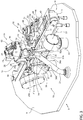
- Figures 2 to 4 illustrate several bottles 1 from which the respective caps 4 are to be removed.
- the apparatus 5 comprises a removal station 6, in which the cap 4 is removed from the respective bottle 1, a following discard station 7, in which a potential defective bottle 1 is intercepted and discarded after the removal of the cap 4, and a belt conveyor 8, which runs through the removal station 6 and the discard station 7 in order to convey the bottles 1 in a continuous manner according to an advancing direction 8a ( Figure 3 ) guided from the removal station 6 to the discard station 7.
- the belt conveyor 8 feeds the bottles 1 with the respective caps 4 to the removal station 6, transfers each bottle 1 without the cap 4 from the removal station 6 to the discard station 7 and transports the checked bottle 1 out of the discard station 7.
- the apparatus 5 comprises a support base 9 on which the belt conveyor 8 and other devices of the removal station 6 and of the discard station 7, described in the following, are attached.
- the removal station 6 comprises a holding system 10 for holding one bottle 1 at a time in a cap removal position, where the bottle 1 stands on a supporting surface 11 in the removal station 6 with its longitudinal axis 2a coinciding with an axis 12 fixed with respect to the removal station 6, and in particular fixed with respect to the support base 9.
- the axis 12 is perpendicular to the supporting surface 11.
- the axis 12 is vertical.
- the supporting surface 11 is defined by the upper portion of the looped belt 13 of the belt conveyor 8.
- the holding system 10 holds the bottle 1 in the cap removal position for at least a time necessary to remove the cap from the bottle, while the belt conveyor 8 continuously moves the looped belt 13, which thus drags underneath the stationary bottle 1.
- the removal station 6 comprises a gripping head 14 provided with a gripper 15 having two jaws 16 and 17 mutually movable along an axis 18 transverse to the fixed axis 12 to grip the cap 4 when the bottle 1 is in the cap removal position.
- the removal station 6 comprises a handling system 19 to move the gripping head 14 to and from the bottle 1 in the cap removal position and to rotate the gripping head 14 about a further axis 20 located on the side of the jaw 16 and perpendicular to a geometric plane defined by the axis 12 and by the axis 18.
- the axis 12 is vertical, therefore said plane is vertical and thus the axis 20 is horizontal.
- the removal station 6 further comprises a discharging pipe 21 anchored to the support base 9 and having an inlet port 22 facing upwards.
- the handling system 19 is suited to move the gripping head 14 between a first position, in which the gripper 15 is above the bottle 1 in the cap removal position in order to remove the cap 4, and a second position, which is the one illustrated by Figures 2 to 4 , in which the gripper 15 is above the inlet port 22 to discharge the cap 4 by gravity, i.e. let the cap 4 fall into the discharging pipe 21 through the inlet port 22.
- the removal station 6 finally comprises an image acquisition device, which is of a known type, is schematically illustrated only in Figure 4 for simplicity and indicated by 23, and is placed so as to acquire a side image of each bottle 1 after the respective cap 4 has been removed.
- the discard station 7 comprises an optical sensor 24 placed above the belt conveyor 8 and oriented downwards in order to detect the passing of each bottle 1 in the discard station 7 and an interception and handling system 25 for removing the detected bottle 1 from the belt conveyor 8, by moving it in a discard direction 8b ( Figure 3 ) transverse to the advancing direction 8a so as to transfer the bottle 1 into a discard collector (not illustrated) on the side of the belt conveyor 8, in the event that the image of the bottle 1 shows a defect, for example the cap 4 has not been removed or the ferrule cap 3 is damaged.
- the belt conveyor 8 comprises a guide 26 placed at the outlet of the discard station 7 and shaped to divert the bottles 1 without a cap 4 and which are not discarded to subsequent means (not illustrated) for conveying or handling or processing (for example, decontaminating) or using the bottles 1 without the respective caps 4.
- the apparatus 5 further comprises an electronic control unit, schematically illustrated only in Figure 4 for simplicity and indicated by 27, to control the holding system 10, the gripper 15, the handling system 19, the image acquisition device 23 and the interception and handling system 25 according to a precise time coordination.
- the electronic control unit 27 is configured to process each bottle image acquired by the image acquisition device 23 in order to verify whether or not the cap is present and control the interception and handling system 25 in order to discard the bottle 1 if the processing of the corresponding image detects the presence of the cap 4.
- the gripping head 14 comprises a frame 28 having at least one side portion, and in particular two side portions 29 and 30 placed on opposite sides of the axis 18, and the handling system 19 comprises at least one support arm, and in particular two support arms 31 and 32, each having a first end 31a, 32a articulated, by means of a pivot-bearing joint, at a point of a corresponding side portion 29, 30 in order to allow the rotation of the gripping head 14 about the axis 20, and the other end 31b, 32b connected to the support base 9 so as to rotate around another axis 33 fixed with respect to the support base 9 to allow the gripping head 14 to move to and from the bottle.
- the articulation point of the support arm 31 with the gripping head 14, and in particular with the side portion 29 of the frame 28, is indicated by 29a in Figure 3 .
- the axis 33 is perpendicular to said plane defined by the axis 12 and by the axis 18. In other words, the axis 33 is parallel to the axis 20.
- the handling system 19 comprises an electric motor 34, which is fixed to the support base 9 and is suited to rotate its own shaft 35 around the axis 33, and the ends 31b and 32b of the two support arms 31 and 32 are fitted on the shaft 35.
- the end 31b, 32b of each arm 31, 32 is connected in a rotating manner to the support base 9 by means of the electric motor 34.
- the electric motor 34 is controlled by the electronic control unit 27.
- the handling system 19 comprises another arm 36, which has one end 36a connected to the support base 9 so as to rotate about the axis 33 independently of the support arms 31 and 32, and a further arm 37, which connects in an articulated manner, and in particular by means of two pivot-bearing joints, the other end 36b of the arm 36 to a point 29b of the side portion 29 so that a rotation of the arm 36 about the axis 33 produces a corresponding rotation of the gripping head 14 about the axis 20.
- the point 29a and the point 29b of the side portion 29, where the support arm 31 and the arm 37 are respectively articulated define a segment 38 parallel to the axis 18.
- the support arm 31, the arm 37, the arm 36 and the segment 38 form an articulated parallelogram in which the arms 31 and 37 are parallel to each other and the arm 36 is parallel to the segment 38.
- the handling system 19 comprises a further electric motor 39, which is fixed to the support base and is suited to rotate its own shaft (not visible in the figures) about the axis 33, and the end 36a of the arm 36 is fitted on the shaft of the electric motor 39.
- the end 36a is connected in a rotating manner to the support base 9 by means of the electric motor 39.
- the shaft of the motor 39 is coupled coaxially and in a disengaged manner to the shaft 35 of the motor 34.
- the electric motor 39 is controlled by the electronic control unit 27.
- the gripping head 14 comprises a box-like body 40, visible in Figures 2 and 3 , supported by the frame 28 and housing an electric actuator 41 ( Figure 4 ), which is suited to close and open the gripper 15.
- the electric actuator 41 is controlled by the electronic control unit 27.
- the holding system 10 comprises an intercepting body 42, which is movable to and from an intercepting position, which is the position illustrated in Figures 2 to 4 , wherein the intercepting body 42 is placed on or above the supporting surface 11 transversely to the advancing direction 8a to stop the bottle 1 in the cap removal position, while the belt conveyor 8 tends to advance the bottle 1 in the advancing direction 8a, making the looped belt 13 drag on the bottom of the stationary bottle 1.
- the belt conveyor 8 transports a plurality of bottles 1, as illustrated in Figures 2 to 4 , consequently the bottles 1 behind the one intercepted by the intercepting body 42 stop against the intercepted bottle 1 and the looped belt 13 drags underneath them.
- the holding system 10 comprises an electric actuator 43, which is fixed to the support base 9 and comprises a shaft 44 rotating about a vertical axis, and the intercepting body 42 consists of an arm, which has an L-shaped first portion 45 ( Figure 4 ) for intercepting the bottle 1 and a second portion 46 fitted on the shaft 44.
- the electric actuator 44 is suited to rotate the shaft 44 between two angular positions such to move the intercepting body 42 to and from said intercepting position.
- the electric actuator 43 is controlled by the electronic control unit 27.
- the holding system 10 further comprises a ring 47, which is movable coaxially to the axis 12 between a raised position, in which the ring 47 is above the ferrule cap 3 of the bottle 1 in order to leave the bottle 1 free, and thus allow the conveyance of the bottles 1 in the advancing direction 8a, and a lowered position, illustrated by Figures 2 to 4 , in which the ring 47 is fitted around the neck 2 of the bottle 1 to retain the latter in the cap removal position.
- the holding system 10 comprises an actuator 48, preferably of electro-pneumatic type, which is fixed to the support base 9 and comprises a vertically movable head 49, and the ring 47 is fixed to the head 49 by means of a support arm 50.
- the actuator 48 is suited to move the head 49 so that the ring 47 moves between said raised position and said lowered position.
- the holding system 10 further comprises a second intercepting body 51, which substantially has the same shape and the same mobility as the intercepting body 42, partially overlaps the intercepting body 42, and is placed with its own L-shaped first portion 52 ( Figure 4 ) in a more advanced position with respect to the portion 45, in the advancing direction 8a, having such an amount that the portion 52 is suited to intercept and stop only the bottle 1 that has already had its cap removed and that precedes the bottle 1 in the cap removal position.
- the electric actuator 43 comprises a further shaft 53, which is parallel to the shaft 44 and rotates about a vertical axis, and the intercepting body 51 has a second portion 54 fitted on the shaft 53.
- the electric actuator 44 is suited to rotate the shaft 53 between two angular positions such to move the intercepting body 53 to and from its own intercepting position in order to stop the bottle 1 that has already had its cap removed and that precedes the bottle 1 in the cap removal position.
- the movement of the intercepting body 51 is synchronized with the movement of the intercepting body 42 so as to delay the entry of the bottle 1 whose cap has just been removed into the discard station 7 in order to allow the potential discard of the preceding bottle 1.
- the movement of the intercepting body 51 to and from its intercepting position occurs with a predefined delay with respect to the movement of the intercepting body 42 to and from its intercepting position.
- the synchronization between the two intercepting bodies 42 and 51 is operated by mechanical means (not illustrated) which couple the two shafts 44 and 53 kinematically and which are housed in the actuator 43, or, according to a further embodiment, is operated by the electronic control unit 27 by controlling two different electric motors which move the two shafts 44 and 53 and which are housed in the body of the actuator 43.
- the interception and handling system 25 of the discard station 7 comprises an intercepting body 55, which is movable to and from an intercepting position, which is the one illustrated in Figure 4 , wherein the intercepting body 55 is placed on or above the supporting surface 11 transversely to the advancing direction 8a to stop the bottle 1 detected by the optical sensor 24, and a pusher 56, which is normally placed on the side the belt conveyor 8, as illustrated in Figure 4 , and is suited to move back and forth across it in the discard direction 8b to remove the bottle 1 from the belt conveyor 8 while the intercepting body 55 prevents the bottle 1 from being transported by the belt conveyor 8.
- the interception and handling system 25 comprises two electric actuators 57 and 58 both fixed to the support base 9, the first being suited to move the intercepting body 55 and the second being suited to move the pusher 56.
- the intercepting body 55 consists of an L-shaped arm having one end 59 ( Figure 4 ) fixed to a rotating shaft 60 of the actuator 57, the latter being suited to rotate the shaft 60 between two angular positions such to move the intercepting body 55 to and from its intercepting position.
- the pusher 56 is connected to a rotating shaft 61 of the actuator 58 by means of an articulated parallelogram 62 so that an angular movement of the shaft 61 is transformed into a translation of the pusher 56.
- the electric actuators 57 and 58 are controlled by the electronic control unit 27.
- the electronic control unit 27 is configured to control the motors 34 and 39 of the handling system 19 and the actuator 41 of the gripping head 14 in the manner described in the following with particular reference to Figures 5 to 11 , which illustrate the apparatus 5 during respective operating steps and according to a same side view, and in particular from the outlet side of the removal station 6, wherein the discard station 7 has been removed for greater clarity.
- the holding system 10 holds a bottle 1 in the cap removal position.
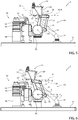
- the gripping head 14 is initially placed over the discharging pipe 21 with the gripper 15 open and the axis 18 of movement of the gripper 15 preferably perpendicular to the axis 12 ( Figure 5 ).
- the initial position of the axis 18 identifies a reference direction indicated by R in Figures 5 to 10 .
- the axis 12 is vertical and, consequently, the axis 18 is initially horizontal.
- the axis of the arm 36 is also initially horizontal (parallel to the reference direction R).
- the support arms 31 and 32 are rotated about the axis 33, counterclockwise on the plane of Figures 5 to 11 , so as to move the gripping head 14 towards the bottle 1.
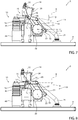
- the arm 36 is rotated about the axis 33, but in the opposite direction with respect to the support arms 31 and 32 (clockwise), according to a predefined angular movement ⁇ to rotate the gripping head 14 about the axis 20 so as to raise the jaw 17 with respect to the jaw 16, i.e. make the axis 18 simply transverse to the axis 12 ( Figure 6 ).
- the angular movement ⁇ of the arm 36 corresponds to a certain angle ⁇ formed between the axis 18 and the reference direction R.
- the arm 36 is rotated back (counterclockwise) by the same angular movement ⁇ in order to rotate the gripping head 14 about the axis 20 so that its axis 18 is again perpendicular to the axis 12, i.e. parallel to the reference direction R, so that the gripper 15 is placed with the jaws 16 and 17 on opposite sides of the cap 15, and then the gripper 15 is closed so as to grip the cap 4 ( Figure 8 ).
- the arm 36 is rotated again in the clockwise direction of the angular movement ⁇ in order to rotate the gripping head 14 about the axis 20 so as to raise the jaw 17 with respect to the jaw 16, i.e. incline the axis 18 by the angle ⁇ again, so as to lift the cap 4 from the ferrule cap 3 substantially only at the jaw 17 ( Figure 9 ).
- the support arms 31 and 32 are rotated back, i.e. clockwise, about the axis 33, so as to move the gripping head 14 away from the bottle 1, while the arm 36 remains stationary. Therefore, as it moves away from the bottle 1, the gripping head 14 remains rotated and, consequently, the axis 18 remains inclined, thus causing a removal of the cap 4 by a pulling movement similar to the one that would be performed manually by an operator ( Figure 10 ) .
- the gripper 15 is opened to release the cap 4, which, falling, enters the discharging pipe 21 through the inlet port 22.
- the main advantage of the apparatus 5 described in the foregoing is an acceleration of the process of removing flip-off caps from bottles so as to render possible its integration in a fast industrial processing line, for example a line for manipulating pharmaceutical substances, while maintaining a gentle manner of removal, substantially analogous to a manual removal.
- the apparatus 5 allows automating the process of removing flip-off caps from bottles without damaging the ferrule cap or the bottle.
- Another advantage of the apparatus 5 is a minimization of the risk of a microbiological contamination of the bottle 1, since the manual intervention of an operator is not required and the parts of the apparatus 5 that enter into contact with the bottle 1 such as, for example, gripper 15, ring 47 and intercepting bodies 42 and 51 of the holding system 10, looped belt 13 of the belt conveyor 8, and intercepting body 55 of the interception and handling system 25, can be manufactured with readily sterilizable or aseptic materials.
- the gripper 15, ring 47 and intercepting bodies 42, 51 and 55 are made of stainless steel.
Landscapes
- Engineering & Computer Science (AREA)
- Mechanical Engineering (AREA)
- Specific Conveyance Elements (AREA)
- Encapsulation Of And Coatings For Semiconductor Or Solid State Devices (AREA)
- Processing And Handling Of Plastics And Other Materials For Molding In General (AREA)
- Filling Of Jars Or Cans And Processes For Cleaning And Sealing Jars (AREA)
Abstract
Description
- This patent application claims priority from
Italian patent application no. 102020000015637 filed on June 29, 2020 - The present invention relates to an apparatus for removing a flip-off type plastic cap from a bottle.
- In particular, the present invention is applicable, advantageously but not exclusively, in the removal of the flip-off cap from a bottle for containing a powdered substance for pharmaceutical use, to which the following description will explicitly refer without thereby losing generality.
- Powdered pharmaceutical substances for preparing liquid solutions or pharmaceutical substances that are already liquid are often contained in bottles of the type comprising a ferrule cap, i.e. a rubber plug provided with an outer metal ferrule having a central hole in order to leave a portion of the rubber plug exposed so that said portion can be perforated by a syringe needle.
- Typically, the bottle comprises a plastic cap attached in a removable manner to the ferrule cap in order to cover said perforable portion. The cap comprises a lower protuberance pressed internally into the hole of the ferrule so as to be held on the ferrule cap and, at the same time, be manually removable by a pulling movement. Such type of cap is called a flip-off cap. Once the cap has been removed, it is possible to perforate the rubber plug with the needle of a syringe in order to inject a solvent into the bottle and produce a liquid solution in the bottle, for example a drug, or in order to withdraw the solution or to withdraw a liquid substance from the bottle.
- In some medical applications, it is necessary to decontaminate the outer surface of the bottle after removing the cap and before perforating the rubber plug with the needle of the syringe. A known process for decontaminating the outer surface of the bottles consists in keeping a large quantity of bottles in an isolated chamber saturated with VHP for a period of time necessary to destroy the microbiological load present on the outer surface of the bottles.
- In order to integrate the bottle decontamination cycle in a pharmaceutical substance handling line, it is necessary to automate the filling of the isolated chamber. However, the flip-off caps were created to be opened manually and an apparatus capable of replacing the manual opening without damaging the ferrule cap or the bottle is not known.
- The object of the present invention is to provide an apparatus for removing a flip-off cap from a bottle for pharmaceutical substances, which apparatus enables automating the removal process in a pharmaceutical substance handling line and, at the same time, is easy and inexpensive to manufacture.
- In accordance with the present invention, an apparatus for removing a flip-off type plastic cap from a bottle is provided, as defined in the appended claims.
- The present invention will now be described with reference to the accompanying drawings, which illustrate a non-limiting embodiment example thereof, wherein:
-
Figure 1 illustrates a bottle with a flip-off type plastic cap; -
Figures 2 and3 illustrate two different axonometric views of an apparatus for removing the cap from the bottle ofFigure 1 , which apparatus is provided according to the principles of the present invention; -
Figure 4 illustrates a plan top view of the apparatus ofFigures 2 and3 ; and -
Figures 5 to 11 illustrate, according to a side view and with some parts removed, the apparatus ofFigures 2 and3 during respective operating steps. - In
Figure 1 ,reference numeral 1 indicates a bottle with a flip-off type cap. Thebottle 1 comprises aneck 2 having an access opening (not illustrated), aferrule cap 3 fixed to theneck 2 for closing the access opening, and a flip-off typeplastic cap 4 attached in a removable manner to theferrule cap 3. Theneck 2, theferrule cap 3 and thecap 4 are coaxial with alongitudinal axis 1a of thebottle 1. - In
Figures 2 to 4 ,reference numeral 5 indicates in generic terms, as a whole, an apparatus for removing the flip-off typeplastic cap 4 from thebottle 1.Figures 2 to 4 illustrateseveral bottles 1 from which therespective caps 4 are to be removed. - The
apparatus 5 comprises a removal station 6, in which thecap 4 is removed from therespective bottle 1, a following discard station 7, in which a potentialdefective bottle 1 is intercepted and discarded after the removal of thecap 4, and abelt conveyor 8, which runs through the removal station 6 and the discard station 7 in order to convey thebottles 1 in a continuous manner according to an advancingdirection 8a (Figure 3 ) guided from the removal station 6 to the discard station 7. In other words, thebelt conveyor 8 feeds thebottles 1 with therespective caps 4 to the removal station 6, transfers eachbottle 1 without thecap 4 from the removal station 6 to the discard station 7 and transports the checkedbottle 1 out of the discard station 7. - The
apparatus 5 comprises asupport base 9 on which thebelt conveyor 8 and other devices of the removal station 6 and of the discard station 7, described in the following, are attached. - The removal station 6 comprises a
holding system 10 for holding onebottle 1 at a time in a cap removal position, where thebottle 1 stands on a supportingsurface 11 in the removal station 6 with its longitudinal axis 2a coinciding with anaxis 12 fixed with respect to the removal station 6, and in particular fixed with respect to thesupport base 9. Preferably, theaxis 12 is perpendicular to the supportingsurface 11. Preferably, theaxis 12 is vertical. The supportingsurface 11 is defined by the upper portion of the loopedbelt 13 of thebelt conveyor 8. Theholding system 10 holds thebottle 1 in the cap removal position for at least a time necessary to remove the cap from the bottle, while thebelt conveyor 8 continuously moves the loopedbelt 13, which thus drags underneath thestationary bottle 1. - The removal station 6 comprises a gripping
head 14 provided with agripper 15 having twojaws axis 18 transverse to thefixed axis 12 to grip thecap 4 when thebottle 1 is in the cap removal position. - The removal station 6 comprises a
handling system 19 to move the grippinghead 14 to and from thebottle 1 in the cap removal position and to rotate the grippinghead 14 about afurther axis 20 located on the side of thejaw 16 and perpendicular to a geometric plane defined by theaxis 12 and by theaxis 18. - Advantageously, the
axis 12 is vertical, therefore said plane is vertical and thus theaxis 20 is horizontal. - The removal station 6 further comprises a
discharging pipe 21 anchored to thesupport base 9 and having aninlet port 22 facing upwards. Thehandling system 19 is suited to move thegripping head 14 between a first position, in which thegripper 15 is above thebottle 1 in the cap removal position in order to remove thecap 4, and a second position, which is the one illustrated byFigures 2 to 4 , in which thegripper 15 is above theinlet port 22 to discharge thecap 4 by gravity, i.e. let thecap 4 fall into thedischarging pipe 21 through theinlet port 22. - The removal station 6 finally comprises an image acquisition device, which is of a known type, is schematically illustrated only in
Figure 4 for simplicity and indicated by 23, and is placed so as to acquire a side image of eachbottle 1 after therespective cap 4 has been removed. - The discard station 7 comprises an
optical sensor 24 placed above thebelt conveyor 8 and oriented downwards in order to detect the passing of eachbottle 1 in the discard station 7 and an interception and handlingsystem 25 for removing the detectedbottle 1 from thebelt conveyor 8, by moving it in adiscard direction 8b (Figure 3 ) transverse to the advancingdirection 8a so as to transfer thebottle 1 into a discard collector (not illustrated) on the side of thebelt conveyor 8, in the event that the image of thebottle 1 shows a defect, for example thecap 4 has not been removed or theferrule cap 3 is damaged. - The
belt conveyor 8 comprises aguide 26 placed at the outlet of the discard station 7 and shaped to divert thebottles 1 without acap 4 and which are not discarded to subsequent means (not illustrated) for conveying or handling or processing (for example, decontaminating) or using thebottles 1 without therespective caps 4. - The
apparatus 5 further comprises an electronic control unit, schematically illustrated only inFigure 4 for simplicity and indicated by 27, to control theholding system 10, thegripper 15, thehandling system 19, theimage acquisition device 23 and the interception andhandling system 25 according to a precise time coordination. Moreover, theelectronic control unit 27 is configured to process each bottle image acquired by theimage acquisition device 23 in order to verify whether or not the cap is present and control the interception and handlingsystem 25 in order to discard thebottle 1 if the processing of the corresponding image detects the presence of thecap 4. - More specifically, still with reference to
Figures 2 to 4 , thegripping head 14 comprises aframe 28 having at least one side portion, and in particular twoside portions axis 18, and thehandling system 19 comprises at least one support arm, and in particular twosupport arms first end corresponding side portion gripping head 14 about theaxis 20, and theother end support base 9 so as to rotate around anotheraxis 33 fixed with respect to thesupport base 9 to allow the grippinghead 14 to move to and from the bottle. - The articulation point of the
support arm 31 with thegripping head 14, and in particular with theside portion 29 of theframe 28, is indicated by 29a inFigure 3 . - Advantageously, the
axis 33 is perpendicular to said plane defined by theaxis 12 and by theaxis 18. In other words, theaxis 33 is parallel to theaxis 20. - With particular reference to
Figures 3 and4 , thehandling system 19 comprises anelectric motor 34, which is fixed to thesupport base 9 and is suited to rotate itsown shaft 35 around theaxis 33, and theends support arms shaft 35. In other words, theend arm support base 9 by means of theelectric motor 34. Theelectric motor 34 is controlled by theelectronic control unit 27. - With particular reference to
Figure 3 , thehandling system 19 comprises anotherarm 36, which has oneend 36a connected to thesupport base 9 so as to rotate about theaxis 33 independently of thesupport arms further arm 37, which connects in an articulated manner, and in particular by means of two pivot-bearing joints, theother end 36b of thearm 36 to apoint 29b of theside portion 29 so that a rotation of thearm 36 about theaxis 33 produces a corresponding rotation of thegripping head 14 about theaxis 20. Preferably, thepoint 29a and thepoint 29b of theside portion 29, where thesupport arm 31 and thearm 37 are respectively articulated, define asegment 38 parallel to theaxis 18. Thesupport arm 31, thearm 37, thearm 36 and thesegment 38 form an articulated parallelogram in which thearms arm 36 is parallel to thesegment 38. - The
handling system 19 comprises a furtherelectric motor 39, which is fixed to the support base and is suited to rotate its own shaft (not visible in the figures) about theaxis 33, and theend 36a of thearm 36 is fitted on the shaft of theelectric motor 39. In other words, theend 36a is connected in a rotating manner to thesupport base 9 by means of theelectric motor 39. In order to increase the stability of thehandling system 19, and simultaneously keep the rotation of thearm 36 independent of the rotation of thesupport arms motor 39 is coupled coaxially and in a disengaged manner to theshaft 35 of themotor 34. Theelectric motor 39 is controlled by theelectronic control unit 27. - The gripping
head 14 comprises a box-like body 40, visible inFigures 2 and3 , supported by theframe 28 and housing an electric actuator 41 (Figure 4 ), which is suited to close and open thegripper 15. Theelectric actuator 41 is controlled by theelectronic control unit 27. - Still with reference to
Figures 2 to 4 , the holdingsystem 10 comprises an interceptingbody 42, which is movable to and from an intercepting position, which is the position illustrated inFigures 2 to 4 , wherein the interceptingbody 42 is placed on or above the supportingsurface 11 transversely to the advancingdirection 8a to stop thebottle 1 in the cap removal position, while thebelt conveyor 8 tends to advance thebottle 1 in the advancingdirection 8a, making the loopedbelt 13 drag on the bottom of thestationary bottle 1. Normally, thebelt conveyor 8 transports a plurality ofbottles 1, as illustrated inFigures 2 to 4 , consequently thebottles 1 behind the one intercepted by the interceptingbody 42 stop against the interceptedbottle 1 and the loopedbelt 13 drags underneath them. - More specifically, the holding
system 10 comprises anelectric actuator 43, which is fixed to thesupport base 9 and comprises ashaft 44 rotating about a vertical axis, and the interceptingbody 42 consists of an arm, which has an L-shaped first portion 45 (Figure 4 ) for intercepting thebottle 1 and asecond portion 46 fitted on theshaft 44. Theelectric actuator 44 is suited to rotate theshaft 44 between two angular positions such to move the interceptingbody 42 to and from said intercepting position. Theelectric actuator 43 is controlled by theelectronic control unit 27. - The holding
system 10 further comprises aring 47, which is movable coaxially to theaxis 12 between a raised position, in which thering 47 is above theferrule cap 3 of thebottle 1 in order to leave thebottle 1 free, and thus allow the conveyance of thebottles 1 in the advancingdirection 8a, and a lowered position, illustrated byFigures 2 to 4 , in which thering 47 is fitted around theneck 2 of thebottle 1 to retain the latter in the cap removal position. - More specifically, the holding
system 10 comprises anactuator 48, preferably of electro-pneumatic type, which is fixed to thesupport base 9 and comprises a verticallymovable head 49, and thering 47 is fixed to thehead 49 by means of asupport arm 50. Theactuator 48 is suited to move thehead 49 so that thering 47 moves between said raised position and said lowered position. - The holding
system 10 further comprises a second interceptingbody 51, which substantially has the same shape and the same mobility as the interceptingbody 42, partially overlaps the interceptingbody 42, and is placed with its own L-shaped first portion 52 (Figure 4 ) in a more advanced position with respect to theportion 45, in the advancingdirection 8a, having such an amount that theportion 52 is suited to intercept and stop only thebottle 1 that has already had its cap removed and that precedes thebottle 1 in the cap removal position. Theelectric actuator 43 comprises afurther shaft 53, which is parallel to theshaft 44 and rotates about a vertical axis, and the interceptingbody 51 has asecond portion 54 fitted on theshaft 53. Theelectric actuator 44 is suited to rotate theshaft 53 between two angular positions such to move the interceptingbody 53 to and from its own intercepting position in order to stop thebottle 1 that has already had its cap removed and that precedes thebottle 1 in the cap removal position. - The movement of the intercepting
body 51 is synchronized with the movement of the interceptingbody 42 so as to delay the entry of thebottle 1 whose cap has just been removed into the discard station 7 in order to allow the potential discard of the precedingbottle 1. In particular, the movement of the interceptingbody 51 to and from its intercepting position occurs with a predefined delay with respect to the movement of the interceptingbody 42 to and from its intercepting position. - The synchronization between the two intercepting
bodies shafts actuator 43, or, according to a further embodiment, is operated by theelectronic control unit 27 by controlling two different electric motors which move the twoshafts actuator 43. - Still with reference to
Figures 2 to 4 , the interception and handlingsystem 25 of the discard station 7 comprises an interceptingbody 55, which is movable to and from an intercepting position, which is the one illustrated inFigure 4 , wherein the interceptingbody 55 is placed on or above the supportingsurface 11 transversely to the advancingdirection 8a to stop thebottle 1 detected by theoptical sensor 24, and apusher 56, which is normally placed on the side thebelt conveyor 8, as illustrated inFigure 4 , and is suited to move back and forth across it in the discarddirection 8b to remove thebottle 1 from thebelt conveyor 8 while the interceptingbody 55 prevents thebottle 1 from being transported by thebelt conveyor 8. - The interception and handling
system 25 comprises twoelectric actuators support base 9, the first being suited to move the interceptingbody 55 and the second being suited to move thepusher 56. In particular, the interceptingbody 55 consists of an L-shaped arm having one end 59 (Figure 4 ) fixed to arotating shaft 60 of theactuator 57, the latter being suited to rotate theshaft 60 between two angular positions such to move the interceptingbody 55 to and from its intercepting position. Thepusher 56 is connected to arotating shaft 61 of theactuator 58 by means of an articulatedparallelogram 62 so that an angular movement of theshaft 61 is transformed into a translation of thepusher 56. - The
electric actuators electronic control unit 27. - With the purpose of removing the
cap 4 from thebottle 1, theelectronic control unit 27 is configured to control themotors handling system 19 and theactuator 41 of the grippinghead 14 in the manner described in the following with particular reference toFigures 5 to 11 , which illustrate theapparatus 5 during respective operating steps and according to a same side view, and in particular from the outlet side of the removal station 6, wherein the discard station 7 has been removed for greater clarity. - In the operating steps illustrated by
Figures 5 to 11 , the holdingsystem 10 holds abottle 1 in the cap removal position. The grippinghead 14 is initially placed over the dischargingpipe 21 with thegripper 15 open and theaxis 18 of movement of thegripper 15 preferably perpendicular to the axis 12 (Figure 5 ). The initial position of theaxis 18 identifies a reference direction indicated by R inFigures 5 to 10 . Preferably, theaxis 12 is vertical and, consequently, theaxis 18 is initially horizontal. Preferably, the axis of thearm 36 is also initially horizontal (parallel to the reference direction R). - The
support arms 31 and 32 (only thearm 31 is visible inFigures 5 to 10 ) are rotated about theaxis 33, counterclockwise on the plane ofFigures 5 to 11 , so as to move the grippinghead 14 towards thebottle 1. Moreover, thearm 36 is rotated about theaxis 33, but in the opposite direction with respect to thesupport arms 31 and 32 (clockwise), according to a predefined angular movement α to rotate the grippinghead 14 about theaxis 20 so as to raise thejaw 17 with respect to thejaw 16, i.e. make theaxis 18 simply transverse to the axis 12 (Figure 6 ). The angular movement α of thearm 36 corresponds to a certain angle β formed between theaxis 18 and the reference direction R. - The movement of the gripping
head 14 towards thebottle 1 continues, while keeping theaxis 18 inclined by the angle β, until thegripper 15 is placed with thejaws cap 4 of the bottle 1 (Figure 7 ). - At this point, the
arm 36 is rotated back (counterclockwise) by the same angular movement α in order to rotate the grippinghead 14 about theaxis 20 so that itsaxis 18 is again perpendicular to theaxis 12, i.e. parallel to the reference direction R, so that thegripper 15 is placed with thejaws cap 15, and then thegripper 15 is closed so as to grip the cap 4 (Figure 8 ). - While the
gripper 15 is closed, thearm 36 is rotated again in the clockwise direction of the angular movement α in order to rotate the grippinghead 14 about theaxis 20 so as to raise thejaw 17 with respect to thejaw 16, i.e. incline theaxis 18 by the angle β again, so as to lift thecap 4 from theferrule cap 3 substantially only at the jaw 17 (Figure 9 ). - At this point, the
support arms axis 33, so as to move the grippinghead 14 away from thebottle 1, while thearm 36 remains stationary. Therefore, as it moves away from thebottle 1, the grippinghead 14 remains rotated and, consequently, theaxis 18 remains inclined, thus causing a removal of thecap 4 by a pulling movement similar to the one that would be performed manually by an operator (Figure 10 ) . - The clockwise rotation of the
support arms gripping head 14 back towards the dischargingpipe 21 and when the discharginghead 14 is located above the dischargingpipe 21, thearm 36 is rotated again in the counterclockwise direction of the angular movement α in order to again make theaxis 18 preferably perpendicular to the axis 12 (Figure 11 ), thus bringing the grippinghead 14 back into the initial position, in particular with thegripper 15 placed above theinlet port 22 of the dischargingpipe 21. - At this point, the
gripper 15 is opened to release thecap 4, which, falling, enters the dischargingpipe 21 through theinlet port 22. - Although the invention described in the foregoing makes particular reference to a very precise embodiment example, it is not to be considered limited to such embodiment example, falling within its scope all those variants, modifications or simplifications covered by the appended claims, such as for example:
- the
frame 28 only has theside portion 29 and there is only thesupport arm 31, so that the handlingsystem 19 has a simpler and lighter structure, even if less robust and mechanically less balanced; or - instead of the
handling system 19, there is a different handling system which comprises an overhead crane placed above thebelt conveyor 8, for supporting and moving the grippinghead 14 to and from thebottle 1, and in particular between a first position, in which thegripper 15 is above thebottle 1, and a second position, in which thegripper 15 is above the dischargingpipe 21, a first actuator mounted, together with the grippinghead 14, on the carriage of the overhead crane in order to lower the grippinghead 14 from the first position until thegripper 15 is placed with itsjaws cap 4 of thebottle 1, and a second actuator which is also mounted on the carriage of the overhead crane in order to rotate the grippinghead 14 about theaxis 20 so as to lift thecap 4 from theferrule cap 3 substantially only at thejaw 17. - The main advantage of the
apparatus 5 described in the foregoing is an acceleration of the process of removing flip-off caps from bottles so as to render possible its integration in a fast industrial processing line, for example a line for manipulating pharmaceutical substances, while maintaining a gentle manner of removal, substantially analogous to a manual removal. In other words, theapparatus 5 allows automating the process of removing flip-off caps from bottles without damaging the ferrule cap or the bottle. - Another advantage of the
apparatus 5 is a minimization of the risk of a microbiological contamination of thebottle 1, since the manual intervention of an operator is not required and the parts of theapparatus 5 that enter into contact with thebottle 1 such as, for example,gripper 15,ring 47 and interceptingbodies system 10, loopedbelt 13 of thebelt conveyor 8, and interceptingbody 55 of the interception and handlingsystem 25, can be manufactured with readily sterilizable or aseptic materials. For example, thegripper 15,ring 47 and interceptingbodies
Claims (13)
- Apparatus for removing a flip-off type plastic cap from a bottle, which comprises a neck (2), a ferrule cap (3) attached to the neck (2) and the plastic cap (4) attached in a removable manner to the ferrule cap (3), the apparatus (5) comprising a removal station (6), which comprises: holding means (10) to hold the bottle (1) in a cap removal position, where the bottle (1) stands on a supporting surface (11) in the removal station (6) with its own longitudinal axis (2a) coinciding with a first axis (12) fixed with respect to the removal station (6) and perpendicular to the supporting surface (11); a gripping head (14) provided with a gripper (15) having a first jaw (16) and a second jaw (17) mutually movable along a second axis (18) transverse to the first axis (12) to grip the plastic cap (4); first handling means (31, 32, 34) to move the gripping head (14) to and from the bottle (1), second handling means (36, 37, 39) to rotate the gripping head (14) about a third axis (20) located on the side of the first jaw (16) and perpendicular to a plane defined by the first axis (12) and by the second axis (18); electronic control means (27) configured to control, in the following order, the first handling means (31, 32, 34) so as to bring the gripping head (14) closer to the bottle (1), the second handling means (36, 37, 39) to rotate the gripping head (14) so as to position the two jaws (16, 17) around the plastic cap (4) with the second axis (18) perpendicular to the first axis (12), the gripping head (14) to close the gripper (15) so as to grip the plastic cap (4), the second handling means (36, 37, 39) to rotate the gripping head (14) around the third axis (20) by a certain angle (β) such as to lift the plastic cap (4) from the ferrule cap (3) substantially only at the second jaw (17), and the first handling means (31, 32, 34) to move the gripping head (14) away from the bottle (1) while the gripping head (14) remains rotated by that angle (β) so as to remove the plastic cap (4) from the ferrule cap (3).
- Apparatus according to claim 1, wherein such a removal station (6) comprises a support base (9) and said first handling means (31, 32, 34) comprise at least a first arm (31, 32), which has a first end (31a), 32a) connected to the gripping head (14) and the other end (31b, 32b) connected to the support base (9) so as to rotate around a fourth axis (33) fixed with respect to the support base (9) to allow the gripping head (14) to move to and from the bottle (1).
- Apparatus according to claim 2, wherein said first handling means (31, 32, 34) comprise a first electric motor (34) fixed to the support base (9) and suited to rotate its own shaft (35) about said fourth axis (33); said other end (31b, 32b) of the first arm (31, 32) being fitted to the shaft (35) of the first electric motor (34).
- Apparatus according to claim 2 or 3, wherein said second handling means (36, 37, 39) comprise a joint for connecting in an articulated manner said first end (31a, 32a) of the first arm (31, 32) to a first point (29a) of the gripping head (14) to enable it to rotate about the third axis (20), a second arm (36), which has a first end (36a) connected to said support base (9) so as to rotate about said fourth axis (33) independently of said first arm (31, 32), and a third arm (37), which connects in an articulated manner the other end (36b) of the second arm (36) to a second point (29b) of the gripping head (14) so that a rotation of the second arm (36) about the fourth axis (33) produces a corresponding rotation of the gripping head (14) about the third axis (20); preferably the first and second points (29a, 29b) of the gripping head (14) being aligned parallel to the second axis (18).
- Apparatus according to claim 4, wherein said second handling means (36, 37, 39) comprise a second electric motor (39) fixed to the support base (9) and suited to rotate its own shaft around said fourth axis (33); said first end (36a) of the second arm (36) being fitted on the shaft of the second electric motor (39).
- Apparatus according to any of the claims from 1 to 5, wherein said gripping head (14) comprises an electric actuator (41) to close and open said gripper (15).
- Apparatus according to any of the claims 1 to 6, wherein said holding means (10) comprise a ring (47) movable coaxially to said first axis (12) between a raised position, wherein the ring (47) is above said ferrule cap (3) to release the bottle (1), and a lowered position, wherein the ring (47) is fitted around the neck (2) of the bottle (1) to retain the latter in said cap removal position.
- Apparatus according to claim 7, wherein said removal station (6) comprises a support base (9) and said holding means (10) comprise a first actuator (48), preferably electro-pneumatic, fixed to the support base (9) and suited to move said ring (47) between said raised position and said lowered position.
- Apparatus according to any of the claims from 1 to 8, and comprising a belt conveyor (8), which defines said supporting surface (11) and is suited to advance the bottle (1) through the removal station (6) in an advancing direction (8a) transverse to said plane so as to transfer the bottle (1) into said cap removal position.
- Apparatus according to claim 9, wherein said holding means (10) comprise an intercepting body (42), which is movable to and from an intercepting position, wherein the intercepting body (42) is placed on or above said supporting surface (11), transverse to the advancing direction (8a), to stop the bottle (1) in said cap removal position, while the belt conveyor (8) tends to advance the bottle (1).
- Apparatus according to claim 10, wherein said removal station (6) comprises a support base (9) and said holding means (10) comprise a second actuator (43) fixed to the support base (9) and suited to move said intercepting body (42) to and from said intercepting position.
- Apparatus according to any of the claims 1 to 11, wherein said removal station (6) comprises a discharging pipe (21) with an inlet port (22) facing upwards; said first handling means (31, 32, 34) being suited to move the gripping head (14) between a first position, where the gripper (15) is above the bottle (1) to remove the plastic cap (4), and a second position, where the gripper (15) is above the inlet port (22) to discharge the plastic cap (4) by gravity.
- Apparatus according to claim 12, wherein said electronic control means (27) are configured to control said first handling means (31, 32, 34) to move the gripping head (14) so as to position the gripper (15) with the second axis (18) perpendicular to the first axis (12) when the gripping head (14) is in the second position, and to control the gripping head (14) to open the gripper (15) so that the plastic cap (4) falls into said inlet port (22).
Applications Claiming Priority (1)
| Application Number | Priority Date | Filing Date | Title |
|---|---|---|---|
| IT102020000015637A IT202000015637A1 (en) | 2020-06-29 | 2020-06-29 | APPARATUS FOR REMOVING A FLIP-OFF TYPE PLASTIC CAP FROM A BOTTLE |
Publications (2)
| Publication Number | Publication Date |
|---|---|
| EP3932816A1 true EP3932816A1 (en) | 2022-01-05 |
| EP3932816B1 EP3932816B1 (en) | 2025-10-01 |
Family
ID=72473823
Family Applications (1)
| Application Number | Title | Priority Date | Filing Date |
|---|---|---|---|
| EP21182605.2A Active EP3932816B1 (en) | 2020-06-29 | 2021-06-29 | Apparatus for removing a flip-off type plastic cap from a bottle |
Country Status (4)
| Country | Link |
|---|---|
| US (1) | US11945707B2 (en) |
| EP (1) | EP3932816B1 (en) |
| CA (1) | CA3123257A1 (en) |
| IT (1) | IT202000015637A1 (en) |
Families Citing this family (1)
| Publication number | Priority date | Publication date | Assignee | Title |
|---|---|---|---|---|
| CN116495688B (en) * | 2023-04-28 | 2026-06-12 | 中国人民解放军陆军军医大学第一附属医院 | A medical bottle opener capable of opening bottles in bulk |
Citations (5)
| Publication number | Priority date | Publication date | Assignee | Title |
|---|---|---|---|---|
| WO1999028724A1 (en) * | 1997-11-27 | 1999-06-10 | A.I. Scientific Pty. Ltd. | A sample distribution apparatus/system |
| WO2003048025A1 (en) * | 2001-11-30 | 2003-06-12 | Forhealth Technologies, Inc. | Automated drug vial safety cap removal |
| US20090198208A1 (en) * | 2008-02-01 | 2009-08-06 | Rescue Dose Ltd. | Dosage dispensing device |
| US20150298321A1 (en) * | 2012-10-16 | 2015-10-22 | Beckman Coulter, Inc. | System and method including specimen gripper |
| EP2457550B1 (en) * | 2005-05-16 | 2016-04-13 | Intelligent Hospital Systems Inc. | Automated pharmacy admixture system (APAS) |
Family Cites Families (19)
| Publication number | Priority date | Publication date | Assignee | Title |
|---|---|---|---|---|
| US3545174A (en) * | 1965-04-28 | 1970-12-08 | Benjamin F Randrup | Indexing and decrowning device |
| US3972420A (en) * | 1971-09-20 | 1976-08-03 | Stock Equipment Company | Crane apparatus |
| US4773285A (en) * | 1985-10-29 | 1988-09-27 | Labatt Brewing Company Limited | Automatic decapper |
| US5481946A (en) * | 1993-05-14 | 1996-01-09 | System Stack, Co., Ltd. | Plug-opening device for sealed container |
| JP2955613B2 (en) * | 1994-09-21 | 1999-10-04 | 株式会社日立製作所 | Analysis equipment |
| US5826409A (en) * | 1996-06-11 | 1998-10-27 | Blackhawk Molding Co., Inc. | Method and apparatus for removing bottle caps from bottles |
| EP1021751A1 (en) * | 1997-10-06 | 2000-07-26 | Capital Vial | A method and apparatus for automatically opening and closing vial lids |
| FR2791337B1 (en) * | 1999-03-26 | 2001-05-04 | Serac Group | DEVICE FOR SUPPORTING A CANTILEVER OF A CONTAINER |
| JP4615135B2 (en) * | 2000-03-31 | 2011-01-19 | シスメックス株式会社 | Reagent dispensing device and automatic sample analyzer using the same |
| JP3980014B2 (en) * | 2004-05-14 | 2007-09-19 | 株式会社アイディエス | Straightening opening device for peelable cap |
| US7409809B1 (en) * | 2007-04-10 | 2008-08-12 | Lars Degen | Automatic test tube decapping device |
| US8297151B1 (en) * | 2009-01-17 | 2012-10-30 | Joseph Huppenthal | Apparatus for opening and closing a specimen vial |
| US8365639B2 (en) * | 2008-11-19 | 2013-02-05 | Motoman, Inc. | Gripping devices and methods thereof |
| WO2011074472A1 (en) * | 2009-12-14 | 2011-06-23 | 株式会社 日立ハイテクノロジーズ | Automatic analyzing device and device for opening and closing cover of reagent container therein |
| US9052299B2 (en) * | 2011-01-25 | 2015-06-09 | Capitol Vial, Inc. | Vial capper/decapper for use with a liquid transfer system |
| ITRE20110111A1 (en) * | 2011-12-23 | 2013-06-24 | Alfa Laval Parma S R L | ASEPTIC FILLING MACHINE |
| US10800565B1 (en) * | 2014-05-07 | 2020-10-13 | Express Scripts Strategic Development, Inc. | Systems and methods for capping |
| EP4051622B1 (en) * | 2019-10-29 | 2026-04-29 | Beckman Coulter, Inc. | Sample tube decapper |
| IT202000014836A1 (en) * | 2020-06-22 | 2021-12-22 | Arol Spa | CONTAINER HANDLING DEVICE FOR CORKING INSTALLATIONS |
-
2020
- 2020-06-29 IT IT102020000015637A patent/IT202000015637A1/en unknown
-
2021
- 2021-06-24 CA CA3123257A patent/CA3123257A1/en active Pending
- 2021-06-24 US US17/357,283 patent/US11945707B2/en active Active
- 2021-06-29 EP EP21182605.2A patent/EP3932816B1/en active Active
Patent Citations (5)
| Publication number | Priority date | Publication date | Assignee | Title |
|---|---|---|---|---|
| WO1999028724A1 (en) * | 1997-11-27 | 1999-06-10 | A.I. Scientific Pty. Ltd. | A sample distribution apparatus/system |
| WO2003048025A1 (en) * | 2001-11-30 | 2003-06-12 | Forhealth Technologies, Inc. | Automated drug vial safety cap removal |
| EP2457550B1 (en) * | 2005-05-16 | 2016-04-13 | Intelligent Hospital Systems Inc. | Automated pharmacy admixture system (APAS) |
| US20090198208A1 (en) * | 2008-02-01 | 2009-08-06 | Rescue Dose Ltd. | Dosage dispensing device |
| US20150298321A1 (en) * | 2012-10-16 | 2015-10-22 | Beckman Coulter, Inc. | System and method including specimen gripper |
Also Published As
| Publication number | Publication date |
|---|---|
| US11945707B2 (en) | 2024-04-02 |
| IT202000015637A1 (en) | 2021-12-29 |
| EP3932816B1 (en) | 2025-10-01 |
| US20210403303A1 (en) | 2021-12-30 |
| CA3123257A1 (en) | 2021-12-29 |
Similar Documents
| Publication | Publication Date | Title |
|---|---|---|
| EP3307629B1 (en) | Method and machine for filling and sealing bottles, cartridges, syringes and the like | |
| JP3980014B2 (en) | Straightening opening device for peelable cap | |
| CN109311550B (en) | Method for processing primary containers for pharmaceutical use for transport along automated processing lines operating in a controlled environment | |
| US20230373671A1 (en) | Closing device for closing pharmaceutical containers, and system for processing pharmaceutical containers | |
| CN107213018A (en) | Automatic dispensation apparatus | |
| TWI589489B (en) | Container supply device | |
| WO2010128384A1 (en) | Machine for inspecting containers and inspection method employing said machine | |
| EP3417884A1 (en) | Sterilizing machine for loose products | |
| CN107533075B (en) | Sample container inclination correcting mechanism and control method thereof | |
| EP3932816B1 (en) | Apparatus for removing a flip-off type plastic cap from a bottle | |
| CN112313151A (en) | A device for extracting medicine containers into bottles from corresponding support elements constituted by trays | |
| CN113874303B (en) | Device for transporting at least one object, in particular a pharmaceutical container | |
| CN218338704U (en) | Automatic medicine feeding device for penicillin bottles | |
| US8297151B1 (en) | Apparatus for opening and closing a specimen vial | |
| CN115321173B (en) | A dispensing mechanism and device for an injection vial | |
| CN114235569B (en) | Automatic breaking force testing system for medicine glass ampoule | |
| JPS63230077A (en) | Automatic germ-free testing device for vial | |
| CN119365764A (en) | Device and method for testing the tightness of containers closed by corresponding membranes | |
| JP2023078777A (en) | container carrier | |
| NL2032976B1 (en) | Container inspection device | |
| CN223919685U (en) | Automatic support entering device | |
| US20060242930A1 (en) | Pharmaceutical bulk-up system | |
| JP3896645B2 (en) | Syringe rejection device | |
| US12534308B2 (en) | Rearranging device | |
| US20210155416A1 (en) | Apparatus and method for the transfer of objects, in particular components for inhalers |
Legal Events
| Date | Code | Title | Description |
|---|---|---|---|
| PUAI | Public reference made under article 153(3) epc to a published international application that has entered the european phase |
Free format text: ORIGINAL CODE: 0009012 |
|
| STAA | Information on the status of an ep patent application or granted ep patent |
Free format text: STATUS: THE APPLICATION HAS BEEN PUBLISHED |
|
| AK | Designated contracting states |
Kind code of ref document: A1 Designated state(s): AL AT BE BG CH CY CZ DE DK EE ES FI FR GB GR HR HU IE IS IT LI LT LU LV MC MK MT NL NO PL PT RO RS SE SI SK SM TR |
|
| B565 | Issuance of search results under rule 164(2) epc |
Effective date: 20210812 |
|
| STAA | Information on the status of an ep patent application or granted ep patent |
Free format text: STATUS: REQUEST FOR EXAMINATION WAS MADE |
|
| 17P | Request for examination filed |
Effective date: 20220630 |
|
| RBV | Designated contracting states (corrected) |
Designated state(s): AL AT BE BG CH CY CZ DE DK EE ES FI FR GB GR HR HU IE IS IT LI LT LU LV MC MK MT NL NO PL PT RO RS SE SI SK SM TR |
|
| STAA | Information on the status of an ep patent application or granted ep patent |
Free format text: STATUS: EXAMINATION IS IN PROGRESS |
|
| 17Q | First examination report despatched |
Effective date: 20230411 |
|
| P01 | Opt-out of the competence of the unified patent court (upc) registered |
Effective date: 20230912 |
|
| GRAP | Despatch of communication of intention to grant a patent |
Free format text: ORIGINAL CODE: EPIDOSNIGR1 |
|
| STAA | Information on the status of an ep patent application or granted ep patent |
Free format text: STATUS: GRANT OF PATENT IS INTENDED |
|
| GRAJ | Information related to disapproval of communication of intention to grant by the applicant or resumption of examination proceedings by the epo deleted |
Free format text: ORIGINAL CODE: EPIDOSDIGR1 |
|
| STAA | Information on the status of an ep patent application or granted ep patent |
Free format text: STATUS: EXAMINATION IS IN PROGRESS |
|
| INTG | Intention to grant announced |
Effective date: 20250219 |
|
| INTC | Intention to grant announced (deleted) | ||
| GRAP | Despatch of communication of intention to grant a patent |
Free format text: ORIGINAL CODE: EPIDOSNIGR1 |
|
| STAA | Information on the status of an ep patent application or granted ep patent |
Free format text: STATUS: GRANT OF PATENT IS INTENDED |
|
| INTG | Intention to grant announced |
Effective date: 20250429 |
|
| GRAS | Grant fee paid |
Free format text: ORIGINAL CODE: EPIDOSNIGR3 |
|
| GRAA | (expected) grant |
Free format text: ORIGINAL CODE: 0009210 |
|
| STAA | Information on the status of an ep patent application or granted ep patent |
Free format text: STATUS: THE PATENT HAS BEEN GRANTED |
|
| AK | Designated contracting states |
Kind code of ref document: B1 Designated state(s): AL AT BE BG CH CY CZ DE DK EE ES FI FR GB GR HR HU IE IS IT LI LT LU LV MC MK MT NL NO PL PT RO RS SE SI SK SM TR |
|
| REG | Reference to a national code |
Ref country code: GB Ref legal event code: FG4D Ref country code: CH Ref legal event code: F10 Free format text: ST27 STATUS EVENT CODE: U-0-0-F10-F00 (AS PROVIDED BY THE NATIONAL OFFICE) Effective date: 20251001 |
|
| REG | Reference to a national code |
Ref country code: DE Ref legal event code: R096 Ref document number: 602021039398 Country of ref document: DE |
|
| REG | Reference to a national code |
Ref country code: IE Ref legal event code: FG4D |
|
| REG | Reference to a national code |
Ref country code: NL Ref legal event code: MP Effective date: 20251001 |
|
| REG | Reference to a national code |
Ref country code: AT Ref legal event code: MK05 Ref document number: 1842335 Country of ref document: AT Kind code of ref document: T Effective date: 20251001 |
|
| PG25 | Lapsed in a contracting state [announced via postgrant information from national office to epo] |
Ref country code: NL Free format text: LAPSE BECAUSE OF FAILURE TO SUBMIT A TRANSLATION OF THE DESCRIPTION OR TO PAY THE FEE WITHIN THE PRESCRIBED TIME-LIMIT Effective date: 20251001 |
|
| PG25 | Lapsed in a contracting state [announced via postgrant information from national office to epo] |
Ref country code: ES Free format text: LAPSE BECAUSE OF FAILURE TO SUBMIT A TRANSLATION OF THE DESCRIPTION OR TO PAY THE FEE WITHIN THE PRESCRIBED TIME-LIMIT Effective date: 20251001 |
|
| REG | Reference to a national code |
Ref country code: LT Ref legal event code: MG9D |
|
| PG25 | Lapsed in a contracting state [announced via postgrant information from national office to epo] |
Ref country code: NO Free format text: LAPSE BECAUSE OF FAILURE TO SUBMIT A TRANSLATION OF THE DESCRIPTION OR TO PAY THE FEE WITHIN THE PRESCRIBED TIME-LIMIT Effective date: 20260101 |
|
| PG25 | Lapsed in a contracting state [announced via postgrant information from national office to epo] |
Ref country code: AT Free format text: LAPSE BECAUSE OF FAILURE TO SUBMIT A TRANSLATION OF THE DESCRIPTION OR TO PAY THE FEE WITHIN THE PRESCRIBED TIME-LIMIT Effective date: 20251001 Ref country code: FI Free format text: LAPSE BECAUSE OF FAILURE TO SUBMIT A TRANSLATION OF THE DESCRIPTION OR TO PAY THE FEE WITHIN THE PRESCRIBED TIME-LIMIT Effective date: 20251001 Ref country code: HR Free format text: LAPSE BECAUSE OF FAILURE TO SUBMIT A TRANSLATION OF THE DESCRIPTION OR TO PAY THE FEE WITHIN THE PRESCRIBED TIME-LIMIT Effective date: 20251001 |
|
| PG25 | Lapsed in a contracting state [announced via postgrant information from national office to epo] |
Ref country code: RS Free format text: LAPSE BECAUSE OF FAILURE TO SUBMIT A TRANSLATION OF THE DESCRIPTION OR TO PAY THE FEE WITHIN THE PRESCRIBED TIME-LIMIT Effective date: 20260101 |
|
| PG25 | Lapsed in a contracting state [announced via postgrant information from national office to epo] |
Ref country code: IS Free format text: LAPSE BECAUSE OF FAILURE TO SUBMIT A TRANSLATION OF THE DESCRIPTION OR TO PAY THE FEE WITHIN THE PRESCRIBED TIME-LIMIT Effective date: 20260201 |
|
| PG25 | Lapsed in a contracting state [announced via postgrant information from national office to epo] |
Ref country code: PT Free format text: LAPSE BECAUSE OF FAILURE TO SUBMIT A TRANSLATION OF THE DESCRIPTION OR TO PAY THE FEE WITHIN THE PRESCRIBED TIME-LIMIT Effective date: 20260202 Ref country code: CZ Free format text: LAPSE BECAUSE OF FAILURE TO SUBMIT A TRANSLATION OF THE DESCRIPTION OR TO PAY THE FEE WITHIN THE PRESCRIBED TIME-LIMIT Effective date: 20251001 |
|
| PG25 | Lapsed in a contracting state [announced via postgrant information from national office to epo] |
Ref country code: PL Free format text: LAPSE BECAUSE OF FAILURE TO SUBMIT A TRANSLATION OF THE DESCRIPTION OR TO PAY THE FEE WITHIN THE PRESCRIBED TIME-LIMIT Effective date: 20251001 |
|
| PG25 | Lapsed in a contracting state [announced via postgrant information from national office to epo] |
Ref country code: LV Free format text: LAPSE BECAUSE OF FAILURE TO SUBMIT A TRANSLATION OF THE DESCRIPTION OR TO PAY THE FEE WITHIN THE PRESCRIBED TIME-LIMIT Effective date: 20251001 |
|
| PG25 | Lapsed in a contracting state [announced via postgrant information from national office to epo] |
Ref country code: BG Free format text: LAPSE BECAUSE OF FAILURE TO SUBMIT A TRANSLATION OF THE DESCRIPTION OR TO PAY THE FEE WITHIN THE PRESCRIBED TIME-LIMIT Effective date: 20251001 |
|
| PG25 | Lapsed in a contracting state [announced via postgrant information from national office to epo] |
Ref country code: LT Free format text: LAPSE BECAUSE OF FAILURE TO SUBMIT A TRANSLATION OF THE DESCRIPTION OR TO PAY THE FEE WITHIN THE PRESCRIBED TIME-LIMIT Effective date: 20251001 |
|
| REG | Reference to a national code |
Ref country code: DE Ref legal event code: R097 Ref document number: 602021039398 Country of ref document: DE |
|
| PG25 | Lapsed in a contracting state [announced via postgrant information from national office to epo] |
Ref country code: SM Free format text: LAPSE BECAUSE OF FAILURE TO SUBMIT A TRANSLATION OF THE DESCRIPTION OR TO PAY THE FEE WITHIN THE PRESCRIBED TIME-LIMIT Effective date: 20251001 |
|
| PG25 | Lapsed in a contracting state [announced via postgrant information from national office to epo] |
Ref country code: DK Free format text: LAPSE BECAUSE OF FAILURE TO SUBMIT A TRANSLATION OF THE DESCRIPTION OR TO PAY THE FEE WITHIN THE PRESCRIBED TIME-LIMIT Effective date: 20251001 |
|
| PG25 | Lapsed in a contracting state [announced via postgrant information from national office to epo] |
Ref country code: IT Free format text: LAPSE BECAUSE OF FAILURE TO SUBMIT A TRANSLATION OF THE DESCRIPTION OR TO PAY THE FEE WITHIN THE PRESCRIBED TIME-LIMIT Effective date: 20251001 |
|
| PGFP | Annual fee paid to national office [announced via postgrant information from national office to epo] |
Ref country code: DE Payment date: 20260623 Year of fee payment: 6 |
|
| PG25 | Lapsed in a contracting state [announced via postgrant information from national office to epo] |
Ref country code: EE Free format text: LAPSE BECAUSE OF FAILURE TO SUBMIT A TRANSLATION OF THE DESCRIPTION OR TO PAY THE FEE WITHIN THE PRESCRIBED TIME-LIMIT Effective date: 20251001 |
|
| PG25 | Lapsed in a contracting state [announced via postgrant information from national office to epo] |
Ref country code: SK Free format text: LAPSE BECAUSE OF FAILURE TO SUBMIT A TRANSLATION OF THE DESCRIPTION OR TO PAY THE FEE WITHIN THE PRESCRIBED TIME-LIMIT Effective date: 20251001 |
|
| PG25 | Lapsed in a contracting state [announced via postgrant information from national office to epo] |
Ref country code: SE Free format text: LAPSE BECAUSE OF FAILURE TO SUBMIT A TRANSLATION OF THE DESCRIPTION OR TO PAY THE FEE WITHIN THE PRESCRIBED TIME-LIMIT Effective date: 20251001 |
|
| PLBE | No opposition filed within time limit |
Free format text: ORIGINAL CODE: 0009261 |
|
| STAA | Information on the status of an ep patent application or granted ep patent |
Free format text: STATUS: NO OPPOSITION FILED WITHIN TIME LIMIT |
|
| REG | Reference to a national code |
Ref country code: CH Ref legal event code: L10 Free format text: ST27 STATUS EVENT CODE: U-0-0-L10-L00 (AS PROVIDED BY THE NATIONAL OFFICE) Effective date: 20260812 |