EP3932813A1 - Reinforcing steel bar binding machine - Google Patents
Reinforcing steel bar binding machine Download PDFInfo
- Publication number
- EP3932813A1 EP3932813A1 EP19916969.9A EP19916969A EP3932813A1 EP 3932813 A1 EP3932813 A1 EP 3932813A1 EP 19916969 A EP19916969 A EP 19916969A EP 3932813 A1 EP3932813 A1 EP 3932813A1
- Authority
- EP
- European Patent Office
- Prior art keywords
- reel
- antenna
- housing
- reel housing
- tying tool
- Prior art date
- Legal status (The legal status is an assumption and is not a legal conclusion. Google has not performed a legal analysis and makes no representation as to the accuracy of the status listed.)
- Withdrawn
Links
Images




Classifications
-
- E—FIXED CONSTRUCTIONS
- E04—BUILDING
- E04G—SCAFFOLDING; FORMS; SHUTTERING; BUILDING IMPLEMENTS OR AIDS, OR THEIR USE; HANDLING BUILDING MATERIALS ON THE SITE; REPAIRING, BREAKING-UP OR OTHER WORK ON EXISTING BUILDINGS
- E04G21/00—Preparing, conveying, or working-up building materials or building elements in situ; Other devices or measures for constructional work
- E04G21/12—Mounting of reinforcing inserts; Prestressing
- E04G21/122—Machines for joining reinforcing bars
- E04G21/123—Wire twisting tools
-
- B—PERFORMING OPERATIONS; TRANSPORTING
- B21—MECHANICAL METAL-WORKING WITHOUT ESSENTIALLY REMOVING MATERIAL; PUNCHING METAL
- B21F—WORKING OR PROCESSING OF METAL WIRE
- B21F15/00—Connecting wire to wire or other metallic material or objects; Connecting parts by means of wire
- B21F15/02—Connecting wire to wire or other metallic material or objects; Connecting parts by means of wire wire with wire
- B21F15/04—Connecting wire to wire or other metallic material or objects; Connecting parts by means of wire wire with wire without additional connecting elements or material, e.g. by twisting
-
- B—PERFORMING OPERATIONS; TRANSPORTING
- B65—CONVEYING; PACKING; STORING; HANDLING THIN OR FILAMENTARY MATERIAL
- B65B—MACHINES, APPARATUS OR DEVICES FOR, OR METHODS OF, PACKAGING ARTICLES OR MATERIALS; UNPACKING
- B65B13/00—Bundling articles
- B65B13/02—Applying and securing binding material around articles or groups of articles, e.g. using strings, wires, strips, bands or tapes
- B65B13/04—Applying and securing binding material around articles or groups of articles, e.g. using strings, wires, strips, bands or tapes with means for guiding the binding material around the articles prior to severing from supply
- B65B13/14—Pairs of carriers or guides movable around opposite sides of the articles
-
- B—PERFORMING OPERATIONS; TRANSPORTING
- B65—CONVEYING; PACKING; STORING; HANDLING THIN OR FILAMENTARY MATERIAL
- B65B—MACHINES, APPARATUS OR DEVICES FOR, OR METHODS OF, PACKAGING ARTICLES OR MATERIALS; UNPACKING
- B65B13/00—Bundling articles
- B65B13/18—Details of, or auxiliary devices used in, bundling machines or bundling tools
- B65B13/24—Securing ends of binding material
- B65B13/28—Securing ends of binding material by twisting
- B65B13/285—Hand tools
Definitions
- the present disclosure relates to a rebar tying tool.
- Patent Literature 1 Various rebar tying tools are known (e.g., Patent Literature 1).
- Patent Literature 1 Japanese Unexamined Patent Application Publication No. 2017-206302
- Rebar tying tools may have wireless communication capabilities to improve performance further.
- the communication is to be highly reliable.
- One or more embodiments of the present disclosure are directed to a rebar tying tool that allows more reliable communication.
- a rebar tying tool includes a reel housing, a guide, and an antenna.
- the reel housing houses a reel on which a wire for tying is wound.
- the guide is located frontward from the reel housing to guide the wire drawn from the reel into a loop.
- the antenna is located inside the reel housing or at a member included in the reel housing.
- FIGs. 1 and 2 are schematic side views of a rebar tying tool 1 in an example.
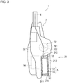
- FIG. 3 is a schematic top view of the rebar tying tool 1 in the example.
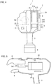
- FIG. 4 is a schematic rear view of the rebar tying tool 1 in the example.
- the positional relationship between the components of the rebar tying tool 1 will be hereafter described using a front-rear direction, a right-left direction, and an up-down direction. These directions are defined with respect to the rebar tying tool 1.
- the term up or upward does not always mean vertically upward.
- the right and the left are hereafter defined with respect to the rebar tying tool 1 viewed from the rear.
- the rebar tying tool 1 is a tool for tying multiple reinforcing bars (rebars) with a tying wire.
- the rebar tying tool 1 also has communication capabilities. The components of the rebar tying tool 1 associated with the typical tying capabilities will first be described briefly, and the components of the rebar tying tool 1 associated with the communication capabilities will then be described.
- the rebar tying tool 1 includes a tying tool body 2 and a grip 3.
- the grip 3 is located under the tying tool body 2. More specifically, the grip 3 extends in the up-down direction, and its upper end is joined to the bottom of the tying tool body 2. An operator can hold the rebar tying tool 1 by gripping the grip 3.
- a battery 8 is detachably attached to the bottom of the grip 3.
- the grip 3 is hollow and accommodates wiring (not shown) in its internal space.
- the wiring electrically connects various components of the tying tool body 2 (described below) and the battery 8 to one another.
- the rebar tying tool 1 is driven with power fed from the battery 8.
- a trigger 31 may be attached to an upper front portion of the grip 3.
- the trigger 31 on the grip 3 can be depressed.
- the operator gripping the grip 3 may depress the trigger 31 with, for example, a forefinger.
- the rebar tying tool 1 performs an operation for tying rebars.
- the tying tool body 2 includes a reel housing 21 and a tying-unit housing 22 (refer in particular to FIGs. 3 and 4 ).
- the reel housing 21 and the tying-unit housing 22 are formed from, for example, resin.
- the reel housing 21 is located in a rear portion of the tying tool body 2.
- the reel housing 21 houses the reel 5.
- the reel 5 includes a reel body 51 and a wire 52 for tying.
- the reel body 51 is shaped like a drum, on which the wire 52 is wound.
- the reel 5 is housed in the reel housing 21 in a manner rotatable about the winding core as the axis of rotation.
- the reel 5 is housed to have the axis of rotation in the right-left direction. As the reel 5 rotates about the axis of rotation, the wire 52 is fed from the reel body 51 into the tying-unit housing 22.
- a specific example structure of the reel housing 21 will be described in detail later.
- the tying-unit housing 22 is located laterally to (e.g., on the left of) and in front of the reel housing 21 and is adj acent to the reel housing 21.
- the internal space in the reel housing 21 (hereafter may be referred to as the reel housing space) and the internal space in the tying-unit housing 22 connect to each other in the front-rear direction with an opening 21a between them (refer to FIG. 4 ).
- the wire 52 drawn from the reel 5 is fed into the tying-unit housing 22 through the opening 21a.
- the tying-unit housing 22 has a pair of guides 6 on its front end.
- the pair of guides 6 are located frontward from the reel housing 21.
- the pair of guides 6 have their tips facing each other in the up-down direction and protruding from the tying-unit housing 22 frontward.
- the wire 52 drawn from the reel 5 is fed to the upper guide 6.
- the wire 52 is guided along the inner surface of the upper guide 6 and the inner surface of the lower guide 6 into a loop.
- the pair of guides 6 guide the wire 52 into a loop.
- the rebar tying tool 1 is moved to have multiple rebars placed between the pair of guides 6. In this state, the wire 52 is fed to the pair of guides 6 and surrounds the multiple rebars.
- FIG. 5 is a schematic view of the tying-unit housing 22 in the example, showing its internal structure.
- FIG. 6 is a schematic functional block diagram of the rebar tying tool 1, showing its electrical configuration.
- the rebar tying tool 1 mainly includes a wire feeder 72, a cutting unit 73, a torsion unit 74, and a control circuit 70. Although these components can be housed in the tying-unit housing 22, the control circuit 70, the wire feeder 72, and the cutting unit 73 are not shown in FIG. 5 for simplicity.
- the wire feeder 72 can feed the wire 52 drawn from the reel 5 and located between the opening 21a and the upper guide 6 to the upper guide 6 inside the tying-unit housing 22.
- the wire feeder 72 may include, for example, a pair of gears 722 that hold, between them, a part of the wire 52 in the longitudinal direction and a feeder motor 721 for rotating the gears 722.
- the feeder motor 721 is located frontward from the reel 5, and has its axis of rotation in the up-down direction.
- the gears 722 are located above the feeder motor 721 and connected to the feeder motor 721. When the feeder motor 721 rotates the gears 722, the wire 52 held between the pair of gears 722 is fed onto the upper guide 6.
- the wire feeder 72 (feeder motor 721) is controlled by the control circuit 70.
- the cutting unit 73 can cut the wire 52 looped by the guides 6 and located, for example, between the wire feeder 72 and the upper guide 6 inside the tying-unit housing 22.
- the cutting unit 73 may include, for example, a cutter that operates in cooperation with the torsion unit 74 (described below).
- the torsion unit 74 includes a torsion motor 741 and a hook 742.
- the hook 742 is between the pair of guides 6 and allows the looped wire 52 to be hooked on it.
- the torsion motor 741 has its axis of rotation in the front-rear direction and is connected to the hook 742 with, for example, a reducer. Referring also to FIGs. 3 and 4 , the torsion motor 741 may be located inside the tying-unit housing 22 in an area adjacent to the reel housing 21 in the right-left direction.
- the torsion motor 741 rotates the hook 742 about the axis of rotation. This allows twisting of the wire 52 hooked on the hook 742, thus reducing the diameter of the loop of the wire 52 and tightening the rebars with the wire 52. In other words, the wire 52 can be used to tie the multiple rebars.
- the cutter in the cutting unit 73 may cut the wire 52 in cooperation with the twisting operation of the torsion unit 74.
- the torsion unit 74 and the cutting unit 73 are controlled by the control circuit 70.
- a power switch 71 may be located on a peripheral surface (e.g., a rear end surface) of the tying-unit housing 22. The operator may operate the power switch 71 to turn on or off the rebar tying tool. The power switch 71 is connected to the control circuit 70.
- control circuit 70 is also connected to the trigger 31. In response to an operation on the power switch 71 and an input from the trigger 31, the control circuit 70 can control the wire feeder 72, the cutting unit 73, and the torsion unit 74.
- the control circuit 70 includes at least one processor to provide control and processing capabilities for implementing various functions, as described in more detail below.
- the at least one processor may be a single integrated circuit (IC), multiple ICs connected to one another for mutual communication, and/or discrete circuits.
- the at least one processor may be implemented in accordance with various known technologies.
- the processor includes one or more circuits or units that perform one or more data computation procedures or processes by, for example, executing instructions stored in an associated memory.
- the processor may be a piece of firmware (e.g., a discrete logic component) to perform one or more data computation procedures or processes.
- the processor may be one or more processors, controllers, microprocessors, microcontrollers, application-specific integrated circuits (ASICs), digital signal processors, programmable logic devices, field-programmable gate arrays, or may include any combination of these devices or components or any combination of other known devices and components, and may implement the functions described below.
- ASICs application-specific integrated circuits
- digital signal processors programmable logic devices, field-programmable gate arrays, or may include any combination of these devices or components or any combination of other known devices and components, and may implement the functions described below.
- control circuit 70 may be implemented with a hardware circuit that can implement such functions without software.
- the operator can use the rebar tying tool 1 to tie multiple rebars in the manner described below.
- the operator first turns on the rebar tying tool 1 by operating the power switch 71.
- the operator then moves the rebar tying tool 1 to place multiple rebars between the pair of guides 6.
- the operator depresses the trigger 31.
- the control circuit 70 controls the various units described above. More specifically, the control circuit 70 controls the wire feeder 72 to feed a predetermined length of the wire 52 toward the guides 6. This forms the wire 52 into a loop surrounding the multiple rebars.
- the control circuit 70 then controls the torsion unit 74 to twist the wire 52 while cutting the wire 52.
- the rebar tying tool 1 can tie the multiple rebars with the wire.
- the rebar tying tool 1 further includes a communication circuit 41 and an antenna 4.
- the antenna 4 allows wireless communication with other communication devices external to the rebar tying tool 1.
- the antenna 4 may be, for example, a metal sheet (e.g., aluminum foil) with a predetermined pattern.
- the communication circuit 41 complies with at least one wireless communication standard, and can wirelessly communicate with devices external to the rebar tying tool 1 with the antenna 4.
- the communication circuit 41 may comply with wireless communication standards including standards for a wireless local area network (LAN), such as Wireless Fidelity (Wi-Fi).
- LAN wireless local area network
- Wi-Fi Wireless Fidelity
- the communication circuit 41 may comply with wireless communication standards including Bluetooth (registered trademark), ZigBee (registered trademark), and Near-Field Communication (NFC).
- the communication circuit 41 may comply with wireless communication standards including standards for a low-power wide-area (LPWA) network.
- LPWA low-power wide-area
- the communication circuit 41 may comply with wireless communication standards including SIGFOX (registered trademark), a LoRa (registered trademark) wide area network (WAN), and Narrowband Internet of Things (NB-IoT).
- SIGFOX registered trademark
- LoRa registered trademark
- WAN wide area network
- NB-IoT Narrowband Internet of Things
- the communication circuit 41 includes at least one processor to provide control and processing capabilities for implementing various functions.
- the at least one processor included in the communication circuit 41 may be implemented in the same manner as the at least one processor included in the control circuit 70 is implemented as described above.
- the communication circuit 41 performs various processes including amplification on a reception signal received by the antenna 4 and obtains data from the reception signal.
- the communication circuit 41 also performs various processes including amplification on a transmission signal including transmission data and wirelessly transmits the resultant transmission signal from the antenna 4.
- the transmission data transmitted by the communication circuit 41 to an external device may include operation count data indicating the operation count, or the number of times the rebar tying tool 1 has been in operation. The operation count is measured by the control circuit 70 counting the number of times the trigger 31 has been depressed.
- the transmission data may also include remaining battery level data indicating the remaining power level of the battery 8.
- the transmission data may include temperature data indicating the temperature of the rebar tying tool 1.
- the temperature data to be transmitted includes the temperature around the motor or the temperature inside the battery.
- the transmission data may include position data indicating the position of the rebar tying tool 1.
- the rebar tying tool 1 may include, for example, a Global Positioning System (GPS) receiver circuit that obtains position data about the rebar tying tool 1 based on signals from GPS positioning satellites.
- GPS Global Positioning System
- the GPS receiver circuit may be included in the communication circuit 41 or may be separate from the communication circuit 41.
- the rebar tying tool 1 may also include, in addition to or instead of the GPS receiver circuit, a circuit for obtaining the position data about the rebar tying tool 1 based on signals from positioning satellites of global navigation satellite systems (GNSSs) other than GPS.
- GNSSs global navigation satellite systems
- Such a circuit may be included in the communication circuit 41 or may be separate from the communication circuit 41. Examples of GNSSs other than GPS include the Global Navigation Satellite System (GLONASS), the Indian Regional Navigational Satellite System (IRNSS), COMPASS, Galileo, and the Quasi-Zenith Satellites System (QZSS).
- GLONASS Global Navigation Satellite System
- the transmission data transmitted by the communication circuit 41 to the external device may be generated by the control circuit 70, by the communication circuit 41, or by the control circuit 70 and the communication circuit 41 in cooperation.
- the external device may, for example, receive transmission data from multiple rebar tying tools 1 and manage the rebar tying tools 1 based on the received transmission data.
- the communication circuit 41 may be mounted on the same substrate 7 as the control circuit 70.
- the substrate 7 is located under the torsion motor 741 in the tying tool body 2.
- the communication circuit 41 may be mounted on a substrate different from the substrate 7 on which the control circuit 70 is mounted.
- the antenna 4 may be mounted on the same substrate as the communication circuit 41 or on a substrate different from the substrate on which the communication circuit 41 is mounted.
- the communication circuit 41 may transmit other items of transmission data in addition to the data described above.
- the communication circuit 41 may have either the reception or transmission function.
- the rebar tying tool 1 includes the antenna 4 in the reel housing 21.
- a specific example structure of the reel housing 21 will be described, before an example position of the antenna 4 is described in more detail.
- the reel housing 21 may include a first side wall (wall) 211, a front wall (wall) 212, and a second side wall (wall) 213.
- the first side wall 211 is located at the boundary between the reel housing 21 and the tying-unit housing 22.
- the first side wall 211 defines the reel housing space in the reel housing 21 and the internal space in the tying-unit housing 22 in the right-left direction.
- the first side wall 211 is, for example, substantially plate-like and has a thickness in the right-left direction.
- the first side wall 211 separates the reel housing 21 and the tying-unit housing 22 from each other, and thus can be either part of the reel housing 21 or part of the tying-unit housing 22.
- the front wall 212 extends in the right-left direction from a front end of the first side wall 211.
- the front wall 212 is also located at the boundary between the reel housing 21 and the tying-unit housing 22.
- the front wall 212 defines the reel housing space in the reel housing 21 and the internal space in the tying-unit housing 22 in the front-rear direction.
- the front wall 212 is, for example, substantially plate-like and has a thickness in the front-rear direction.
- the front wall 212 also separates the reel housing 21 and the tying-unit housing 22 from each other, and thus can be either part of the reel housing 21 or part of the tying-unit housing 22.
- the opening 21a is in, for example, an upper surface of the front wall 212 and forms a through-hole in the front wall 212 in the front-rear direction.
- the wire 52 drawn from the reel 5 in the reel housing space is fed into the tying-unit housing 22 through the opening 21a.
- the second side wall 213 faces the first side wall 211 across the reel housing space in the right-left direction.
- the second side wall 211 is, for example, substantially plate-like and has a thickness in the right-left direction.
- the first side wall 211 and the second side wall 213 sandwich the reel 5 on both sides in the direction of the winding core of the reel 5 (the right-left direction in this example).
- the second side wall 213 has a front end connected to the front wall 212.
- the second side wall 213 may be installed in the reel housing 21 in a manner to be open and closed.
- the second side wall 213 may have its front end attached to the front wall 212 with a hinge 2131 (refer to FIG. 2 ).
- the hinge 2131 connects the end of the second side wall 213 to the front wall 212 in a manner pivotable about the axis of pivot in the up-down direction.
- the second side wall 213 can thus be open and closed like a door.
- FIG. 7 is a top view of the rebar tying tool 1 in the example, with its second side wall 213 being open. As illustrated in FIG.
- the second side wall 213 is open about its front end (hinge 2131) in a direction in which its rear end is away from the first side wall 211.
- the reel housing space is thus open, allowing the operator to attach and detach the reel 5 through the opening.
- the second side wall 213 may also be hereafter referred to as the open-closed member 213.
- the first side wall 211 may have an attachment protrusion 2111 on its main surface adjacent to the reel housing.
- the attachment protrusion 2111 protrudes toward the open-closed member 213 in the right-left direction.
- the open-closed member 213 may have an attachment protrusion 2132 on its main surface adjacent to the reel housing.
- the attachment protrusion 2132 faces the attachment protrusion 2111 and protrudes toward the first side wall 211 in the right-left direction.
- the reel 5 has, on both sides of its axis of rotation, recesses to fit the attachment protrusion 2111 and the attachment protrusion 2132.
- the recesses on the reel 5 fit the attachment protrusion 2111 and the attachment protrusion 2132 to allow the reel 5 to be housed in the reel housing 21 in a rotatable manner.
- the reel housing 21 may further include a connector 214.
- the connector 214 is located rearward from the reel 5. In the closed state, the connector 214 connects the first side wall 211 and the open-closed member 213 to each other.
- the connector 214 may be rod-like and extends in the right-left direction.
- the connector 214 has one end connected to the first side wall 211 and the other end removably connected to the open-closed member 213.
- the other end of the connector 214 and the open-closed member 213 may both include engagement portions. The respective engagement portions are engaged with each other in the closed state to maintain the open-closed member 213 in the closed state.
- the connector 214 may not have the other end removably connected to the open-closed member 213.
- the connector 214 may have the other end fixed to the open-closed member 213 and may have one end removably connected to the first side wall 211.
- the antenna 4 in this reel housing 21 may be located at the open-closed member 213. More specifically, the antenna 4 may be located on one surface of the open-closed member 213. In this case, the antenna 4 may be covered with an insulating protective member. This protects the antenna 4 from the external environment. In some embodiments, the antenna 4 may be embedded in the open-closed member 213.
- the antenna 4 in the reel housing 21 can perform more reliable communication in the manner described below.
- the reel housing 21 is located above the grip 3 as described above (refer to FIG. 4 ).
- the grip 3 is gripped by a hand of the operator.
- the antenna can also be covered by the hand of the operator, possibly causing less reliable communication.
- the rebar tying tool 1 includes the antenna 4 located in the reel housing 21.
- the hand of the operator gripping the grip 3 can be at a larger distance from the antenna 4, thus reducing the likelihood of less reliable communication. In other words, this structure allows more reliable communication.
- the reel housing 21 is located nearer the rear end than the guides 6 as described above.
- This structure also allows communication with higher performance.
- the structure in which an antenna is located near the guides 6 will now be described.
- multiple rebars are placed between the pair of guides 6 during the tying operation.
- the rebars are conductive.
- the antenna may perform less reliable communication.
- the rebar tying tool 1 includes the antenna 4 located in the reel housing 21. This allows the antenna 4 to be at a larger distance from the guides 6, and thus allows the antenna 4 to be at a larger distance from the rebars during the tying operation. This reduces the likelihood of less reliable communication during the tying operation. In other words, this structure allows more reliable communication.
- the antenna 4 may be located in the reel housing 21 or may be embedded in members included in the reel housing 21 (in any of, for example, the first side wall 211, the front wall 212, the open-closed member 213, and the connector 214). Although the antenna 4 may be at any position in the reel housing 21, the position of the antenna 4 in a specific example will be described.
- the antenna 4 may be in a rear area of the reel housing 21.
- the antenna 4 may be located in an area nearer a rear end (e.g., a rear end surface of the first side wall 211 or the open-closed member 213) than a front end (e.g., the front wall 212) of the reel housing 21.
- the antenna 4 may be located in an area rearward from the middle of the reel housing 21 in the front-rear direction.
- the antenna 4 may be located on a rear end surface of the open-closed member 213. This structure allows the antenna 4 to be at a still larger distance from the guides 6, and thus allows the antenna 4 to be at a still larger distance from the rebars during the tying operation. This structure allows still more reliable communication.
- the antenna 4 may be located in an upper area in the reel housing 21 (an area opposite to the grip 3). In other words, the antenna 4 may be located in an area nearer an upper end than a lower end of the reel housing. In other words, the antenna 4 may be located in an area upward from the middle of the reel housing 21 in the up-down direction. In a specific example, the antenna 4 may be located on an upper end surface of the open-closed member 213. This structure allows the antenna 4 to be at a still larger distance from the grip 3. This structure allows still more reliable communication.
- the structure in which the antenna 4 is located at the open-closed member (second side wall) 213 as illustrated in FIG. 4 allows still more reliable communication as described below.
- the torsion motor 741 in the torsion unit 74 may be located inside the tying-unit housing 22 in an area adjacent to the reel housing 21 in the right-left direction (refer to FIGs. 3 and 4 ).
- the first side wall 211 of the reel housing 21 is relatively near the torsion motor 741, whereas the open-closed member (second side wall) 213 is relatively less near the torsion motor 741.
- a drive current flowing through the torsion motor 741 during the tying operation can cause electromagnetic waves to be generated from the torsion motor 741.
- such a drive current can cause less reliable communication.
- the antenna 4 may be located at the open-closed member 213, instead of being located at the first side wall 211, to be at a larger distance from the torsion motor 741.
- the antenna 4 is thus less susceptible to electromagnetic waves from the torsion motor 741. This structure allows still more reliable communication.
- the antenna 4 may be located at the first side wall 211, instead of being located at the open-closed member 213. More specifically, the antenna 4 may be located on a surface of the first side wall 211 to which the reel 5 is attached. This structure allows the antenna 4 to be at a smaller distance from the substrate 7 (refer to FIG. 4 ). This structure thus shortens the wiring length.
- the antenna 4 may be located on the surface of the connector 214 or inside the connector 214, instead of being located at the open-closed member 213.
- the connector 214 is located rearward from the reel 5, allowing the antenna 4 to be at a larger distance from the guides 6.
- the connector 214 may be rod-like and extend in the right-left direction as descried above.
- the antenna 4 may be located on a rear portion of the surface of the connector 214.
- the structure in which the antenna 4 is located on a main surface of the plate-like second side wall 213 opposite to the reel housing space will now be described.
- the antenna 4 has a space on its right unoccupied by any part of the rebar tying tool 1, but has a space on its left occupied by part of the rebar tying tool 1.
- the antenna 4 In contrast, in the structure in which the antenna 4 is located on a rear portion of the connector 214, the antenna 4 has a space on its rear, and also, for example, below the antenna 4 occupied by less part of the rebar tying tool 1.
- the parts of the rebar tying tool 1 can possibly obstruct communication capabilities.
- the antenna 4 located on a rear portion of the connector 214 can thus reduce the likelihood of less reliable communication.
- FIG. 8 is a schematic side view of a rebar tying tool 1A in another example.
- the rebar tying tool 1A has the same structure as the rebar tying tool 1 except the structure of the reel housing 21.
- the reel housing 21 in the rebar tying tool 1A may hereafter be referred to as a reel housing 21A.
- the position of the reel housing 21Ain the rebar tying tool lA is the same as the position of the reel housing 21 in the rebar tying tool 1.
- the reel housing 21A includes a box 211A, and an open-closed member 212A that is pivotable up and down.
- the box 211A has an upper opening and accommodates the reel 5.
- the front wall of the box 211A has an opening that connects to the internal space in the tying-unit housing 22.
- the wire 52 drawn from the reel 5 is fed into the tying-unit housing 22 through the opening.
- the open-closed member 212A to be open or closed can cover the upper opening in the box 211A.
- the open-closed member 212A may also be referred to as a cover.
- the open-closed member 212A is pivotally connected to, for example, the box 211A with the hinge 213A in between. More specifically, for example, the hinge 213A may connect a rear end of the open-closed member 212A to a rear end of the box 211A in a manner pivotable about the axis of pivot in the right-left direction. This allows the open-closed member 212A to be open and closed like a lid.
- FIG. 9 is a schematic side view of the rebar tying tool 1A in the example, with its open-closed member 212A being open. With the open-closed member 212A open, the box 211A is open upward, allowing the operator to attach or detach the reel 5 through the upper opening of the box 211A.
- This rebar tying tool 1A also includes the antenna 4 located in the reel housing 21A.
- This structure also allows more reliable communication, similarly to the rebar tying tool 1.
- the reel housing 21A may include the antenna 4 at any location.
- the antenna 4 may be located in a rear area of the reel housing 21, in an upper area of the reel housing 21, or in one of the side walls (walls) of the box 211A more away from the torsion motor 741.
- the antenna 4 may be located on one surface of or inside the box 211A in the reel housing 21A, or on one surface of or inside the open-closed member 212A.
- the antenna 4 may be mounted to avoid overlapping the reel 5 in the reel housing 21 (refer to FIG. 9 ).
Landscapes
- Engineering & Computer Science (AREA)
- Mechanical Engineering (AREA)
- Architecture (AREA)
- Civil Engineering (AREA)
- Structural Engineering (AREA)
- Basic Packing Technique (AREA)
- Wire Processing (AREA)
- Hand Tools For Fitting Together And Separating, Or Other Hand Tools (AREA)
Abstract
Description
- The present disclosure relates to a rebar tying tool.
- Various rebar tying tools are known (e.g., Patent Literature 1).
- Patent Literature 1:
Japanese Unexamined Patent Application Publication No. 2017-206302 - Rebar tying tools may have wireless communication capabilities to improve performance further. For such tools, the communication is to be highly reliable.
- One or more embodiments of the present disclosure are directed to a rebar tying tool that allows more reliable communication.
- A rebar tying tool according to an embodiment includes a reel housing, a guide, and an antenna. The reel housing houses a reel on which a wire for tying is wound. The guide is located frontward from the reel housing to guide the wire drawn from the reel into a loop. The antenna is located inside the reel housing or at a member included in the reel housing.
- This structure allows more reliable communication.
-
-
FIG. 1 is a schematic side view of a rebar tying tool in an example. -
FIG. 2 is a schematic side view of the rebar tying tool in the example. -
FIG. 3 is a schematic top view of the rebar tying tool in the example. -
FIG. 4 is a schematic rear view of the rebar tying tool in the example. -
FIG. 5 is a schematic view of the rebar tying tool in the example, showing its internal structure. -
FIG. 6 is a functional block diagram of the rebar tying tool in the example. -
FIG. 7 is a schematic side view of the rebar tying tool in the example, with its open-closed member being open. -
FIG. 8 is a schematic side view of a rebar tying tool in another example. -
FIG. 9 is a schematic side view of the rebar tying tool in the other example, with its open-closed member being open. -
FIGs. 1 and2 are schematic side views of arebar tying tool 1 in an example.FIG. 3 is a schematic top view of therebar tying tool 1 in the example.FIG. 4 is a schematic rear view of therebar tying tool 1 in the example. The positional relationship between the components of therebar tying tool 1 will be hereafter described using a front-rear direction, a right-left direction, and an up-down direction. These directions are defined with respect to therebar tying tool 1. Thus, for example, the term up or upward does not always mean vertically upward. The right and the left are hereafter defined with respect to therebar tying tool 1 viewed from the rear. - The
rebar tying tool 1 is a tool for tying multiple reinforcing bars (rebars) with a tying wire. Therebar tying tool 1 also has communication capabilities. The components of therebar tying tool 1 associated with the typical tying capabilities will first be described briefly, and the components of therebar tying tool 1 associated with the communication capabilities will then be described. - As illustrated in
FIGs. 1 to 4 , therebar tying tool 1 includes atying tool body 2 and agrip 3. Thegrip 3 is located under thetying tool body 2. More specifically, thegrip 3 extends in the up-down direction, and its upper end is joined to the bottom of thetying tool body 2. An operator can hold therebar tying tool 1 by gripping thegrip 3. - A
battery 8 is detachably attached to the bottom of thegrip 3. Thegrip 3 is hollow and accommodates wiring (not shown) in its internal space. The wiring electrically connects various components of the tying tool body 2 (described below) and thebattery 8 to one another. Therebar tying tool 1 is driven with power fed from thebattery 8. - As illustrated in
FIGs. 1 and2 , atrigger 31 may be attached to an upper front portion of thegrip 3. Thetrigger 31 on thegrip 3 can be depressed. The operator gripping thegrip 3 may depress thetrigger 31 with, for example, a forefinger. In response to thetrigger 31 being depressed, therebar tying tool 1 performs an operation for tying rebars. - The
tying tool body 2 includes areel housing 21 and a tying-unit housing 22 (refer in particular toFIGs. 3 and4 ). The reel housing 21 and the tying-unit housing 22 are formed from, for example, resin. - The
reel housing 21 is located in a rear portion of thetying tool body 2. Thereel housing 21 houses thereel 5. Thereel 5 includes areel body 51 and awire 52 for tying. Thereel body 51 is shaped like a drum, on which thewire 52 is wound. Thereel 5 is housed in thereel housing 21 in a manner rotatable about the winding core as the axis of rotation. Thereel 5 is housed to have the axis of rotation in the right-left direction. As thereel 5 rotates about the axis of rotation, thewire 52 is fed from thereel body 51 into the tying-unit housing 22. A specific example structure of thereel housing 21 will be described in detail later. - The tying-
unit housing 22 is located laterally to (e.g., on the left of) and in front of thereel housing 21 and is adj acent to thereel housing 21. The internal space in the reel housing 21 (hereafter may be referred to as the reel housing space) and the internal space in the tying-unit housing 22 connect to each other in the front-rear direction with an opening 21a between them (refer toFIG. 4 ). Thewire 52 drawn from thereel 5 is fed into the tying-unit housing 22 through the opening 21a. - The tying-
unit housing 22 has a pair ofguides 6 on its front end. In other words, the pair ofguides 6 are located frontward from thereel housing 21. In the illustrated example, the pair ofguides 6 have their tips facing each other in the up-down direction and protruding from the tying-unit housing 22 frontward. Thewire 52 drawn from thereel 5 is fed to theupper guide 6. As thewire 52 is drawn further, thewire 52 is guided along the inner surface of theupper guide 6 and the inner surface of thelower guide 6 into a loop. In other words, the pair ofguides 6 guide thewire 52 into a loop. Therebar tying tool 1 is moved to have multiple rebars placed between the pair ofguides 6. In this state, thewire 52 is fed to the pair ofguides 6 and surrounds the multiple rebars. -
FIG. 5 is a schematic view of the tying-unit housing 22 in the example, showing its internal structure.FIG. 6 is a schematic functional block diagram of therebar tying tool 1, showing its electrical configuration. Referring toFIG. 6 , therebar tying tool 1 mainly includes awire feeder 72, a cuttingunit 73, atorsion unit 74, and acontrol circuit 70. Although these components can be housed in the tying-unit housing 22, thecontrol circuit 70, thewire feeder 72, and the cuttingunit 73 are not shown inFIG. 5 for simplicity. - The
wire feeder 72 can feed thewire 52 drawn from thereel 5 and located between theopening 21a and theupper guide 6 to theupper guide 6 inside the tying-unit housing 22. Thewire feeder 72 may include, for example, a pair ofgears 722 that hold, between them, a part of thewire 52 in the longitudinal direction and afeeder motor 721 for rotating thegears 722. Thefeeder motor 721 is located frontward from thereel 5, and has its axis of rotation in the up-down direction. Thegears 722 are located above thefeeder motor 721 and connected to thefeeder motor 721. When thefeeder motor 721 rotates thegears 722, thewire 52 held between the pair ofgears 722 is fed onto theupper guide 6. The wire feeder 72 (feeder motor 721) is controlled by thecontrol circuit 70. - The cutting
unit 73 can cut thewire 52 looped by theguides 6 and located, for example, between thewire feeder 72 and theupper guide 6 inside the tying-unit housing 22. The cuttingunit 73 may include, for example, a cutter that operates in cooperation with the torsion unit 74 (described below). - The
torsion unit 74 includes atorsion motor 741 and ahook 742. Thehook 742 is between the pair ofguides 6 and allows the loopedwire 52 to be hooked on it. Thetorsion motor 741 has its axis of rotation in the front-rear direction and is connected to thehook 742 with, for example, a reducer. Referring also toFIGs. 3 and4 , thetorsion motor 741 may be located inside the tying-unit housing 22 in an area adjacent to thereel housing 21 in the right-left direction. - The
torsion motor 741 rotates thehook 742 about the axis of rotation. This allows twisting of thewire 52 hooked on thehook 742, thus reducing the diameter of the loop of thewire 52 and tightening the rebars with thewire 52. In other words, thewire 52 can be used to tie the multiple rebars. The cutter in the cuttingunit 73 may cut thewire 52 in cooperation with the twisting operation of thetorsion unit 74. Thetorsion unit 74 and the cuttingunit 73 are controlled by thecontrol circuit 70. - Referring to
FIG. 4 , apower switch 71 may be located on a peripheral surface (e.g., a rear end surface) of the tying-unit housing 22. The operator may operate thepower switch 71 to turn on or off the rebar tying tool. Thepower switch 71 is connected to thecontrol circuit 70. - Referring to
FIG. 6 , thecontrol circuit 70 is also connected to thetrigger 31. In response to an operation on thepower switch 71 and an input from thetrigger 31, thecontrol circuit 70 can control thewire feeder 72, the cuttingunit 73, and thetorsion unit 74. - The
control circuit 70 includes at least one processor to provide control and processing capabilities for implementing various functions, as described in more detail below. - In various embodiments, the at least one processor may be a single integrated circuit (IC), multiple ICs connected to one another for mutual communication, and/or discrete circuits. The at least one processor may be implemented in accordance with various known technologies.
- In one embodiment, the processor includes one or more circuits or units that perform one or more data computation procedures or processes by, for example, executing instructions stored in an associated memory. In another embodiment, the processor may be a piece of firmware (e.g., a discrete logic component) to perform one or more data computation procedures or processes.
- In various embodiments, the processor may be one or more processors, controllers, microprocessors, microcontrollers, application-specific integrated circuits (ASICs), digital signal processors, programmable logic devices, field-programmable gate arrays, or may include any combination of these devices or components or any combination of other known devices and components, and may implement the functions described below.
- All or some of the functions of the
control circuit 70 may be implemented with a hardware circuit that can implement such functions without software. - The operator can use the
rebar tying tool 1 to tie multiple rebars in the manner described below. The operator first turns on therebar tying tool 1 by operating thepower switch 71. The operator then moves therebar tying tool 1 to place multiple rebars between the pair ofguides 6. In this state, the operator depresses thetrigger 31. In response to thetrigger 31 being depressed, thecontrol circuit 70 controls the various units described above. More specifically, thecontrol circuit 70 controls thewire feeder 72 to feed a predetermined length of thewire 52 toward theguides 6. This forms thewire 52 into a loop surrounding the multiple rebars. Thecontrol circuit 70 then controls thetorsion unit 74 to twist thewire 52 while cutting thewire 52. Through the above process, therebar tying tool 1 can tie the multiple rebars with the wire. - The communication capabilities of the
rebar tying tool 1 will now be described. Therebar tying tool 1 further includes acommunication circuit 41 and anantenna 4. Theantenna 4 allows wireless communication with other communication devices external to therebar tying tool 1. Theantenna 4 may be, for example, a metal sheet (e.g., aluminum foil) with a predetermined pattern. Thecommunication circuit 41 complies with at least one wireless communication standard, and can wirelessly communicate with devices external to therebar tying tool 1 with theantenna 4. - The
communication circuit 41 may comply with wireless communication standards including standards for a wireless local area network (LAN), such as Wireless Fidelity (Wi-Fi). For example, thecommunication circuit 41 may comply with wireless communication standards including Bluetooth (registered trademark), ZigBee (registered trademark), and Near-Field Communication (NFC). Thecommunication circuit 41 may comply with wireless communication standards including standards for a low-power wide-area (LPWA) network. For example, thecommunication circuit 41 may comply with wireless communication standards including SIGFOX (registered trademark), a LoRa (registered trademark) wide area network (WAN), and Narrowband Internet of Things (NB-IoT). - The
communication circuit 41 includes at least one processor to provide control and processing capabilities for implementing various functions. The at least one processor included in thecommunication circuit 41 may be implemented in the same manner as the at least one processor included in thecontrol circuit 70 is implemented as described above. - The
communication circuit 41 performs various processes including amplification on a reception signal received by theantenna 4 and obtains data from the reception signal. Thecommunication circuit 41 also performs various processes including amplification on a transmission signal including transmission data and wirelessly transmits the resultant transmission signal from theantenna 4. - The transmission data transmitted by the
communication circuit 41 to an external device may include operation count data indicating the operation count, or the number of times therebar tying tool 1 has been in operation. The operation count is measured by thecontrol circuit 70 counting the number of times thetrigger 31 has been depressed. The transmission data may also include remaining battery level data indicating the remaining power level of thebattery 8. When therebar tying tool 1 includes a temperature sensor that detects its temperature, the transmission data may include temperature data indicating the temperature of therebar tying tool 1. The temperature data to be transmitted includes the temperature around the motor or the temperature inside the battery. When therebar tying tool 1 can identify its position, the transmission data may include position data indicating the position of therebar tying tool 1. In this case, therebar tying tool 1 may include, for example, a Global Positioning System (GPS) receiver circuit that obtains position data about therebar tying tool 1 based on signals from GPS positioning satellites. The GPS receiver circuit may be included in thecommunication circuit 41 or may be separate from thecommunication circuit 41. Therebar tying tool 1 may also include, in addition to or instead of the GPS receiver circuit, a circuit for obtaining the position data about therebar tying tool 1 based on signals from positioning satellites of global navigation satellite systems (GNSSs) other than GPS. Such a circuit may be included in thecommunication circuit 41 or may be separate from thecommunication circuit 41. Examples of GNSSs other than GPS include the Global Navigation Satellite System (GLONASS), the Indian Regional Navigational Satellite System (IRNSS), COMPASS, Galileo, and the Quasi-Zenith Satellites System (QZSS). - The transmission data transmitted by the
communication circuit 41 to the external device may be generated by thecontrol circuit 70, by thecommunication circuit 41, or by thecontrol circuit 70 and thecommunication circuit 41 in cooperation. - The external device may, for example, receive transmission data from multiple
rebar tying tools 1 and manage therebar tying tools 1 based on the received transmission data. - The
communication circuit 41 may be mounted on thesame substrate 7 as thecontrol circuit 70. In the example inFIG. 5 , thesubstrate 7 is located under thetorsion motor 741 in the tyingtool body 2. Thecommunication circuit 41 may be mounted on a substrate different from thesubstrate 7 on which thecontrol circuit 70 is mounted. Theantenna 4 may be mounted on the same substrate as thecommunication circuit 41 or on a substrate different from the substrate on which thecommunication circuit 41 is mounted. - The
communication circuit 41 may transmit other items of transmission data in addition to the data described above. Thecommunication circuit 41 may have either the reception or transmission function. - The
rebar tying tool 1 includes theantenna 4 in thereel housing 21. A specific example structure of thereel housing 21 will be described, before an example position of theantenna 4 is described in more detail. - As illustrated in
FIGs. 3 and4 , thereel housing 21 may include a first side wall (wall) 211, a front wall (wall) 212, and a second side wall (wall) 213. Thefirst side wall 211 is located at the boundary between thereel housing 21 and the tying-unit housing 22. Thefirst side wall 211 defines the reel housing space in thereel housing 21 and the internal space in the tying-unit housing 22 in the right-left direction. Thefirst side wall 211 is, for example, substantially plate-like and has a thickness in the right-left direction. Thefirst side wall 211 separates thereel housing 21 and the tying-unit housing 22 from each other, and thus can be either part of thereel housing 21 or part of the tying-unit housing 22. - The
front wall 212 extends in the right-left direction from a front end of thefirst side wall 211. Thefront wall 212 is also located at the boundary between thereel housing 21 and the tying-unit housing 22. Thefront wall 212 defines the reel housing space in thereel housing 21 and the internal space in the tying-unit housing 22 in the front-rear direction. Thefront wall 212 is, for example, substantially plate-like and has a thickness in the front-rear direction. Thefront wall 212 also separates thereel housing 21 and the tying-unit housing 22 from each other, and thus can be either part of thereel housing 21 or part of the tying-unit housing 22. Theopening 21a is in, for example, an upper surface of thefront wall 212 and forms a through-hole in thefront wall 212 in the front-rear direction. Thewire 52 drawn from thereel 5 in the reel housing space is fed into the tying-unit housing 22 through theopening 21a. - The
second side wall 213 faces thefirst side wall 211 across the reel housing space in the right-left direction. Thesecond side wall 211 is, for example, substantially plate-like and has a thickness in the right-left direction. Thefirst side wall 211 and thesecond side wall 213 sandwich thereel 5 on both sides in the direction of the winding core of the reel 5 (the right-left direction in this example). Thesecond side wall 213 has a front end connected to thefront wall 212. - The
second side wall 213 may be installed in thereel housing 21 in a manner to be open and closed. In a specific example, thesecond side wall 213 may have its front end attached to thefront wall 212 with a hinge 2131 (refer toFIG. 2 ). Thehinge 2131 connects the end of thesecond side wall 213 to thefront wall 212 in a manner pivotable about the axis of pivot in the up-down direction. Thesecond side wall 213 can thus be open and closed like a door.FIG. 7 is a top view of therebar tying tool 1 in the example, with itssecond side wall 213 being open. As illustrated inFIG. 7 , thesecond side wall 213 is open about its front end (hinge 2131) in a direction in which its rear end is away from thefirst side wall 211. The reel housing space is thus open, allowing the operator to attach and detach thereel 5 through the opening. Thesecond side wall 213 may also be hereafter referred to as the open-closedmember 213. - As illustrated in
FIG. 7 , thefirst side wall 211 may have anattachment protrusion 2111 on its main surface adjacent to the reel housing. Theattachment protrusion 2111 protrudes toward the open-closedmember 213 in the right-left direction. The open-closedmember 213 may have anattachment protrusion 2132 on its main surface adjacent to the reel housing. When the open-closedmember 213 is closed (closed state), theattachment protrusion 2132 faces theattachment protrusion 2111 and protrudes toward thefirst side wall 211 in the right-left direction. Thereel 5 has, on both sides of its axis of rotation, recesses to fit theattachment protrusion 2111 and theattachment protrusion 2132. The recesses on thereel 5 fit theattachment protrusion 2111 and theattachment protrusion 2132 to allow thereel 5 to be housed in thereel housing 21 in a rotatable manner. - The
reel housing 21 may further include aconnector 214. Theconnector 214 is located rearward from thereel 5. In the closed state, theconnector 214 connects thefirst side wall 211 and the open-closedmember 213 to each other. Theconnector 214 may be rod-like and extends in the right-left direction. Theconnector 214 has one end connected to thefirst side wall 211 and the other end removably connected to the open-closedmember 213. For example, the other end of theconnector 214 and the open-closedmember 213 may both include engagement portions. The respective engagement portions are engaged with each other in the closed state to maintain the open-closedmember 213 in the closed state. - The
connector 214 may not have the other end removably connected to the open-closedmember 213. For example, theconnector 214 may have the other end fixed to the open-closedmember 213 and may have one end removably connected to thefirst side wall 211. - As illustrated in
FIG. 4 , theantenna 4 in thisreel housing 21 may be located at the open-closedmember 213. More specifically, theantenna 4 may be located on one surface of the open-closedmember 213. In this case, theantenna 4 may be covered with an insulating protective member. This protects theantenna 4 from the external environment. In some embodiments, theantenna 4 may be embedded in the open-closedmember 213. - The
antenna 4 in thereel housing 21 can perform more reliable communication in the manner described below. - More specifically, the
reel housing 21 is located above thegrip 3 as described above (refer toFIG. 4 ). For comparison, the structure in which an antenna is located on thegrip 3 will now be described. Thegrip 3 is gripped by a hand of the operator. The antenna can also be covered by the hand of the operator, possibly causing less reliable communication. In contrast, therebar tying tool 1 includes theantenna 4 located in thereel housing 21. The hand of the operator gripping thegrip 3 can be at a larger distance from theantenna 4, thus reducing the likelihood of less reliable communication. In other words, this structure allows more reliable communication. - Further, the
reel housing 21 is located nearer the rear end than theguides 6 as described above. This structure also allows communication with higher performance. For comparison, the structure in which an antenna is located near theguides 6 will now be described. As described above, multiple rebars are placed between the pair ofguides 6 during the tying operation. The rebars are conductive. When the antenna approaches the rebars, the antenna may perform less reliable communication. In contrast, therebar tying tool 1 includes theantenna 4 located in thereel housing 21. This allows theantenna 4 to be at a larger distance from theguides 6, and thus allows theantenna 4 to be at a larger distance from the rebars during the tying operation. This reduces the likelihood of less reliable communication during the tying operation. In other words, this structure allows more reliable communication. - The
antenna 4 may be located in thereel housing 21 or may be embedded in members included in the reel housing 21 (in any of, for example, thefirst side wall 211, thefront wall 212, the open-closedmember 213, and the connector 214). Although theantenna 4 may be at any position in thereel housing 21, the position of theantenna 4 in a specific example will be described. - For example, the
antenna 4 may be in a rear area of thereel housing 21. In other words, theantenna 4 may be located in an area nearer a rear end (e.g., a rear end surface of thefirst side wall 211 or the open-closed member 213) than a front end (e.g., the front wall 212) of thereel housing 21. In other words, theantenna 4 may be located in an area rearward from the middle of thereel housing 21 in the front-rear direction. In a specific example, as shown inFIG. 4 , theantenna 4 may be located on a rear end surface of the open-closedmember 213. This structure allows theantenna 4 to be at a still larger distance from theguides 6, and thus allows theantenna 4 to be at a still larger distance from the rebars during the tying operation. This structure allows still more reliable communication. - Further, the
antenna 4 may be located in an upper area in the reel housing 21 (an area opposite to the grip 3). In other words, theantenna 4 may be located in an area nearer an upper end than a lower end of the reel housing. In other words, theantenna 4 may be located in an area upward from the middle of thereel housing 21 in the up-down direction. In a specific example, theantenna 4 may be located on an upper end surface of the open-closedmember 213. This structure allows theantenna 4 to be at a still larger distance from thegrip 3. This structure allows still more reliable communication. - The structure in which the
antenna 4 is located at the open-closed member (second side wall) 213 as illustrated inFIG. 4 allows still more reliable communication as described below. - In the above example, the
torsion motor 741 in thetorsion unit 74 may be located inside the tying-unit housing 22 in an area adjacent to thereel housing 21 in the right-left direction (refer toFIGs. 3 and4 ). Thus, thefirst side wall 211 of thereel housing 21 is relatively near thetorsion motor 741, whereas the open-closed member (second side wall) 213 is relatively less near thetorsion motor 741. - A drive current flowing through the
torsion motor 741 during the tying operation can cause electromagnetic waves to be generated from thetorsion motor 741. In the structure in which the antenna is near thetorsion motor 741, such a drive current can cause less reliable communication. - In contrast, the
antenna 4 may be located at the open-closedmember 213, instead of being located at thefirst side wall 211, to be at a larger distance from thetorsion motor 741. Theantenna 4 is thus less susceptible to electromagnetic waves from thetorsion motor 741. This structure allows still more reliable communication. - The
antenna 4 may be located at thefirst side wall 211, instead of being located at the open-closedmember 213. More specifically, theantenna 4 may be located on a surface of thefirst side wall 211 to which thereel 5 is attached. This structure allows theantenna 4 to be at a smaller distance from the substrate 7 (refer toFIG. 4 ). This structure thus shortens the wiring length. - The
antenna 4 may be located on the surface of theconnector 214 or inside theconnector 214, instead of being located at the open-closedmember 213. Theconnector 214 is located rearward from thereel 5, allowing theantenna 4 to be at a larger distance from theguides 6. - The
connector 214 may be rod-like and extend in the right-left direction as descried above. In this case, theantenna 4 may be located on a rear portion of the surface of theconnector 214. For comparison, the structure in which theantenna 4 is located on a main surface of the plate-likesecond side wall 213 opposite to the reel housing space will now be described. In this structure, theantenna 4 has a space on its right unoccupied by any part of therebar tying tool 1, but has a space on its left occupied by part of therebar tying tool 1. In contrast, in the structure in which theantenna 4 is located on a rear portion of theconnector 214, theantenna 4 has a space on its rear, and also, for example, below theantenna 4 occupied by less part of therebar tying tool 1. The parts of therebar tying tool 1 can possibly obstruct communication capabilities. Theantenna 4 located on a rear portion of theconnector 214 can thus reduce the likelihood of less reliable communication. -
FIG. 8 is a schematic side view of arebar tying tool 1A in another example. Therebar tying tool 1A has the same structure as therebar tying tool 1 except the structure of thereel housing 21. Thereel housing 21 in therebar tying tool 1A may hereafter be referred to as areel housing 21A. The position of the reel housing 21Ain the rebar tying tool lAis the same as the position of thereel housing 21 in therebar tying tool 1. - The
reel housing 21A includes abox 211A, and an open-closedmember 212A that is pivotable up and down. Thebox 211A has an upper opening and accommodates thereel 5. Similarly to therebar tying tool 1, the front wall of thebox 211A has an opening that connects to the internal space in the tying-unit housing 22. Thewire 52 drawn from thereel 5 is fed into the tying-unit housing 22 through the opening. - The open-closed
member 212A to be open or closed can cover the upper opening in thebox 211A. The open-closedmember 212A may also be referred to as a cover. The open-closed member 212Ais pivotally connected to, for example, thebox 211A with thehinge 213A in between. More specifically, for example, thehinge 213A may connect a rear end of the open-closedmember 212A to a rear end of thebox 211A in a manner pivotable about the axis of pivot in the right-left direction. This allows the open-closedmember 212A to be open and closed like a lid. -
FIG. 9 is a schematic side view of therebar tying tool 1A in the example, with its open-closedmember 212A being open. With the open-closedmember 212A open, thebox 211A is open upward, allowing the operator to attach or detach thereel 5 through the upper opening of thebox 211A. - This
rebar tying tool 1A also includes theantenna 4 located in thereel housing 21A. This structure also allows more reliable communication, similarly to therebar tying tool 1. Thereel housing 21A may include theantenna 4 at any location. For example, theantenna 4 may be located in a rear area of thereel housing 21, in an upper area of thereel housing 21, or in one of the side walls (walls) of thebox 211A more away from thetorsion motor 741. Theantenna 4 may be located on one surface of or inside thebox 211A in thereel housing 21A, or on one surface of or inside the open-closedmember 212A. - The
antenna 4 may be mounted to avoid overlapping thereel 5 in the reel housing 21 (refer toFIG. 9 ). - The
rebar tying tool 1 has been described in detail as above, but the foregoing structures are illustrative in all respects, and the disclosure is not limited to the above structures. All the features of the embodiments and the modifications described above may be combined in use unless any contradiction arises. Many modifications not specifically described above may be implemented without departing from the scope of the disclosure. -
- 1, 1A
- rebar tying tool
- 2
- tying tool body
- 3
- grip
- 4
- antenna
- 6
- guide
- 21
- reel housing
- 211
- first side wall
- 213
- second side wall (open-closed member)
- 214
- connector
Claims (7)
- A rebar tying tool, comprising:a reel housing configured to house a reel on which a wire for tying is wound;a guide located frontward from the reel housing to guide the wire drawn from the reel into a loop; andan antenna located inside the reel housing or at a member included in the reel housing.
- The rebar tying tool according to claim 1, wherein
the antenna is located in an area nearer a rear end of the reel housing than a front end of the reel housing. - The rebar tying tool according to claim 1 or claim 2, wherein
the antenna is located in an area nearer an upper end of the reel housing than a lower end of the reel housing. - The rebar tying tool according to any one of claims 1 to 3, further comprising:a torsion motor configured to twist the wire drawn from the reel,wherein the reel housing includes a first wall to which the reel is attachable,the first wall separates the torsion motor from the reel, andthe antenna is located adjacent to a position of the first wall at which the reel is attached.
- The rebar tying tool according to any one of claims 1 to 3, whereinthe reel housing includesa first wall to which the reel is attachable,a second wall located to sandwich the reel together with the first wall, anda connector to connect the first wall and the second wall, andthe antenna is located at the connector.
- The rebar tying tool according to any one of claims 1 to 3, further comprising:a torsion motor configured to twist the wire drawn from the reel,wherein the reel housing includesa first wall to which the reel is attachable, anda second wall located to sandwich the reel together with the first wall,the first wall separates the torsion motor from the reel, andthe antenna is located at the second wall.
- The rebar tying tool according to any one of claims 1 to 3, whereinthe reel housing includes an open-closed member configured to open and close a space in the reel housing accommodating the reel, andthe antenna is located at the open-closed member.
Applications Claiming Priority (1)
| Application Number | Priority Date | Filing Date | Title |
|---|---|---|---|
| PCT/JP2019/007520 WO2020174603A1 (en) | 2019-02-27 | 2019-02-27 | Reinforcing steel bar binding machine |
Publications (2)
| Publication Number | Publication Date |
|---|---|
| EP3932813A1 true EP3932813A1 (en) | 2022-01-05 |
| EP3932813A4 EP3932813A4 (en) | 2022-12-07 |
Family
ID=72239646
Family Applications (1)
| Application Number | Title | Priority Date | Filing Date |
|---|---|---|---|
| EP19916969.9A Withdrawn EP3932813A4 (en) | 2019-02-27 | 2019-02-27 | REINFORCING STEEL BAR BINDING MACHINE |
Country Status (5)
| Country | Link |
|---|---|
| US (1) | US12559956B2 (en) |
| EP (1) | EP3932813A4 (en) |
| JP (1) | JP7213945B2 (en) |
| CN (1) | CN113474258A (en) |
| WO (1) | WO2020174603A1 (en) |
Families Citing this family (2)
| Publication number | Priority date | Publication date | Assignee | Title |
|---|---|---|---|---|
| JP2023075730A (en) * | 2021-11-19 | 2023-05-31 | 株式会社マキタ | Rebar binding machine and reel |
| JP7828554B2 (en) | 2022-04-08 | 2026-03-12 | マックス株式会社 | power tools |
Family Cites Families (19)
| Publication number | Priority date | Publication date | Assignee | Title |
|---|---|---|---|---|
| JP3206935B2 (en) * | 1991-07-05 | 2001-09-10 | 有限会社リョーイチ | Binding device |
| JP2983124B2 (en) * | 1993-04-27 | 1999-11-29 | 瓜生製作株式会社 | Management method of screw tightening work in torque control wrench |
| JPH11169982A (en) * | 1997-12-12 | 1999-06-29 | Max Co Ltd | Brake mechanism of wire reel in reinforcing bar binding machine |
| WO2003028917A1 (en) * | 2001-09-28 | 2003-04-10 | Max Kabushiki Kaisha | Reinforcement binding machine, reel, and method of detecting rotation of reel |
| JP4211059B2 (en) * | 2004-01-09 | 2009-01-21 | マックス株式会社 | Reinforcing bar binding machine, wire reel and wire reel identification method |
| JP4140561B2 (en) * | 2004-06-18 | 2008-08-27 | マックス株式会社 | Reinforcing bar binding machine and wire reel |
| JP4952153B2 (en) | 2006-09-07 | 2012-06-13 | セイコーエプソン株式会社 | Printing apparatus and printing method |
| GB0621428D0 (en) * | 2006-10-27 | 2006-12-06 | Tymatic Ltd | Consumables authentication |
| JP2008202390A (en) * | 2007-01-25 | 2008-09-04 | Max Co Ltd | Wire reel of reinforcement binder |
| JP2008213069A (en) * | 2007-03-01 | 2008-09-18 | Matsushita Electric Works Ltd | Power tool |
| JP5532610B2 (en) | 2008-05-19 | 2014-06-25 | マックス株式会社 | Wire reel and rebar binding machine |
| JP5740563B2 (en) | 2009-09-25 | 2015-06-24 | パナソニックIpマネジメント株式会社 | Electric tool |
| JP2014166662A (en) * | 2013-02-28 | 2014-09-11 | Rohm Co Ltd | Electric power tool and control system of the same |
| CN203921254U (en) | 2014-06-27 | 2014-11-05 | 华建威 | Full-automatic steel bar binding machine |
| JP2017189822A (en) * | 2016-04-11 | 2017-10-19 | 株式会社マルイ | Hand-held electric power tool, electric binding machine with attachment and extension attachment |
| JP6698425B2 (en) * | 2016-05-20 | 2020-05-27 | 株式会社マキタ | Rebar binding machine |
| CN106143983B (en) * | 2016-08-12 | 2018-03-23 | 杭州鼎巅科技有限公司 | A kind of compact holds the mechanical structure and application method of wrapping machine |
| CN207902801U (en) * | 2017-10-27 | 2018-09-25 | 中磐建设集团有限公司 | A kind of adjustable building iron binding apparatus |
| CN108343250B (en) | 2018-05-03 | 2019-06-18 | 广东顺德华焱电子科技有限公司 | A kind of reinforcing-bar binding machine and its changeable type pipette tips and working method |
-
2019
- 2019-02-27 WO PCT/JP2019/007520 patent/WO2020174603A1/en not_active Ceased
- 2019-02-27 JP JP2021501450A patent/JP7213945B2/en active Active
- 2019-02-27 US US17/434,010 patent/US12559956B2/en active Active
- 2019-02-27 CN CN201980093029.XA patent/CN113474258A/en active Pending
- 2019-02-27 EP EP19916969.9A patent/EP3932813A4/en not_active Withdrawn
Also Published As
| Publication number | Publication date |
|---|---|
| US20220154479A1 (en) | 2022-05-19 |
| CN113474258A (en) | 2021-10-01 |
| WO2020174603A1 (en) | 2020-09-03 |
| EP3932813A4 (en) | 2022-12-07 |
| JPWO2020174603A1 (en) | 2020-09-03 |
| JP7213945B2 (en) | 2023-01-27 |
| US12559956B2 (en) | 2026-02-24 |
Similar Documents
| Publication | Publication Date | Title |
|---|---|---|
| US12559956B2 (en) | Rebar tying tool | |
| US7461805B2 (en) | Fishing reel, fishing data display device, and fishing data display system | |
| CN109386206B (en) | Vehicle control device and vehicle control method | |
| CN109154160A (en) | Rebar Binding Machine | |
| WO2020002596A1 (en) | Dispensing control system, method of controlling a dispensing device and computer program background | |
| US20240246219A1 (en) | Smart accessory storage device | |
| US12569973B2 (en) | Control device of electric power tool, electric power tool control method, and computer readable storage medium storing program for performing method of electric power tool control | |
| EP4258105A1 (en) | Electric power tool, and program for electric power tool | |
| CN105660559A (en) | Electrical reel | |
| JP6771171B2 (en) | Wiring equipment members | |
| WO2025052651A1 (en) | Cutting system and cutting tool | |
| JP7153885B2 (en) | Electric tool | |
| US12144334B2 (en) | Fishing information management system | |
| JP7563633B1 (en) | Cutting system and power supply device | |
| JP6964247B2 (en) | Electric tool | |
| JP7828554B2 (en) | power tools | |
| JP2008221349A (en) | Power tool | |
| US20170077766A1 (en) | Power receiving apparatus and method for preventing unfair use | |
| JP2018015868A (en) | Electric tool | |
| EP3624129A1 (en) | Dispensing control system | |
| CN119998523A (en) | Steel bar tying machine | |
| KR20130044486A (en) | Wireless remote control apparatus for voyage of ship | |
| CN105342618A (en) | Wrist-set arm length measuring-transmitting device | |
| JP2005003652A (en) | Water depth detection method and water depth detection device | |
| JP2013184626A (en) | Transmitter receiver |
Legal Events
| Date | Code | Title | Description |
|---|---|---|---|
| STAA | Information on the status of an ep patent application or granted ep patent |
Free format text: STATUS: THE INTERNATIONAL PUBLICATION HAS BEEN MADE |
|
| PUAI | Public reference made under article 153(3) epc to a published international application that has entered the european phase |
Free format text: ORIGINAL CODE: 0009012 |
|
| STAA | Information on the status of an ep patent application or granted ep patent |
Free format text: STATUS: REQUEST FOR EXAMINATION WAS MADE |
|
| 17P | Request for examination filed |
Effective date: 20210825 |
|
| AK | Designated contracting states |
Kind code of ref document: A1 Designated state(s): AL AT BE BG CH CY CZ DE DK EE ES FI FR GB GR HR HU IE IS IT LI LT LU LV MC MK MT NL NO PL PT RO RS SE SI SK SM TR |
|
| DAV | Request for validation of the european patent (deleted) | ||
| DAX | Request for extension of the european patent (deleted) | ||
| A4 | Supplementary search report drawn up and despatched |
Effective date: 20221107 |
|
| RIC1 | Information provided on ipc code assigned before grant |
Ipc: B65B 13/28 20060101ALI20221101BHEP Ipc: B65B 13/18 20060101AFI20221101BHEP |
|
| P01 | Opt-out of the competence of the unified patent court (upc) registered |
Effective date: 20230505 |
|
| RIN1 | Information on inventor provided before grant (corrected) |
Inventor name: MITO, TAKASHI |
|
| STAA | Information on the status of an ep patent application or granted ep patent |
Free format text: STATUS: EXAMINATION IS IN PROGRESS |
|
| 17Q | First examination report despatched |
Effective date: 20240416 |
|
| STAA | Information on the status of an ep patent application or granted ep patent |
Free format text: STATUS: THE APPLICATION HAS BEEN WITHDRAWN |
|
| 18W | Application withdrawn |
Effective date: 20240729 |