EP3932786B1 - Work vehicle - Google Patents
Work vehicle Download PDFInfo
- Publication number
- EP3932786B1 EP3932786B1 EP21181953.7A EP21181953A EP3932786B1 EP 3932786 B1 EP3932786 B1 EP 3932786B1 EP 21181953 A EP21181953 A EP 21181953A EP 3932786 B1 EP3932786 B1 EP 3932786B1
- Authority
- EP
- European Patent Office
- Prior art keywords
- fixation
- fender
- vibration insulating
- seat base
- holes
- Prior art date
- Legal status (The legal status is an assumption and is not a legal conclusion. Google has not performed a legal analysis and makes no representation as to the accuracy of the status listed.)
- Active
Links
Images


Classifications
-
- B—PERFORMING OPERATIONS; TRANSPORTING
- B60—VEHICLES IN GENERAL
- B60R—VEHICLES, VEHICLE FITTINGS, OR VEHICLE PARTS, NOT OTHERWISE PROVIDED FOR
- B60R21/00—Arrangements or fittings on vehicles for protecting or preventing injuries to occupants or pedestrians in case of accidents or other traffic risks
- B60R21/02—Occupant safety arrangements or fittings, e.g. crash pads
- B60R21/13—Roll-over protection
- B60R21/131—Protective devices for drivers in case of overturning of tractors
-
- B—PERFORMING OPERATIONS; TRANSPORTING
- B62—LAND VEHICLES FOR TRAVELLING OTHERWISE THAN ON RAILS
- B62D—MOTOR VEHICLES; TRAILERS
- B62D49/00—Tractors
- B62D49/06—Tractors adapted for multi-purpose use
-
- B—PERFORMING OPERATIONS; TRANSPORTING
- B62—LAND VEHICLES FOR TRAVELLING OTHERWISE THAN ON RAILS
- B62D—MOTOR VEHICLES; TRAILERS
- B62D25/00—Superstructure or monocoque structure sub-units; Parts or details thereof not otherwise provided for
- B62D25/08—Front or rear portions
- B62D25/16—Mud-guards or wings; Wheel cover panels
- B62D25/168—Mud guards for utility vehicles
-
- B—PERFORMING OPERATIONS; TRANSPORTING
- B62—LAND VEHICLES FOR TRAVELLING OTHERWISE THAN ON RAILS
- B62D—MOTOR VEHICLES; TRAILERS
- B62D33/00—Superstructures for load-carrying vehicles
- B62D33/06—Drivers' cabs
- B62D33/0617—Drivers' cabs for tractors or off-the-road vehicles
-
- B—PERFORMING OPERATIONS; TRANSPORTING
- B60—VEHICLES IN GENERAL
- B60R—VEHICLES, VEHICLE FITTINGS, OR VEHICLE PARTS, NOT OTHERWISE PROVIDED FOR
- B60R3/00—Arrangements of steps or ladders facilitating access to or on the vehicle, e.g. running-boards
-
- B—PERFORMING OPERATIONS; TRANSPORTING
- B60—VEHICLES IN GENERAL
- B60Y—INDEXING SCHEME RELATING TO ASPECTS CROSS-CUTTING VEHICLE TECHNOLOGY
- B60Y2200/00—Type of vehicle
- B60Y2200/20—Off-Road Vehicles
- B60Y2200/22—Agricultural vehicles
- B60Y2200/221—Tractors
Definitions
- the disclosure relates to a technique of a work vehicle.
- JP 2006-117148 A discloses a tractor in which left and right rear wheel fenders are connected to a driver's step provided to a driver's seat. In the tractor, vibration from the rear wheel fenders may be transmitted to the driver's step. Therefore, it is desired to suppress the vibration transmitted from the rear wheel fenders to the driver's step.
- the document EP 3 470 583 A2 describes support member that supports a driver's seat, disposed in a rear portion of a machine body, and left and right rear-wheel fenders disposed at left and right lateral portions of the support member.
- a control unit is supported between the left and right fenders, and at a lower side of a rear portion of a rear side of the driver's seat in the support member.
- a tractor wherein hot-air blocking plates, each of which is interposed between a prime mover unit and a driving unit, have a common basic shape and serve as sharable elements, thereby accommodating the various types of specifications of the prime mover units and the driving units having different sizes by cutting the outer edges of the hot-air blocking plates.
- the document KR 2015 0145034 A relates to a fender support of a tractor and a tractor having the same.
- the fender support comprises: a pair of left and right fender frames fixated to a transmission case, and supporting a rear wheel fender; a connection frame fixated to the transmission case, and mutually connecting the left and right fender frames; and a support frame coupled to a rear end of each fender frame, and enabling a fuel tank to be spaced from the transmission case to be supported.
- the fender may comprise a fixation hole that is opened in a direction in which the fender and the ROPS are arrayed and through which a fastener used for fixation to the ROPS is inserted, and the second vibration insulating portion may have a hole through which the fastener is inserted and is inserted through the fixation hole.
- the work vehicle may comprise a reinforcing portion that reinforces the fender; and a third vibration insulating portion having a vibration insulating property and interposed between the reinforcing portion and the ROPS.
- the third vibration insulating portion may be used in common with the second vibration insulating portion.
- the fender may comprise a first portion fixed to the ROPS, and a second portion covering a radially outer portion of the rear wheel, and the reinforcing portion may connect the first portion and the second portion.
- the fender may comprise a fixing part fixed to the step while contacting the step.
- the work vehicle may comprise a mission case containing a power transmission mechanism; a first supporting portion that is provided to the mission case and supports the step from below and to which the step is fixed; and a fourth vibration insulating portion having a vibration insulating property and interposed between the first supporting portion and the step.
- the work vehicle may further comprise a mission case containing a power transmission mechanism; a second supporting portion that is provided to the mission case and supports the seat base from below and to which the seat base is fixed; and a fifth vibration insulating portion having a vibration insulating property and interposed between the second supporting portion and the seat base.
- vibration transmitted from the fender to the step can be suppressed.
- vibration transmitted from the fender to the step can be better suppressed.
- vibration transmitted from the fender to the step can be better suppressed.
- vibration transmitted from the fender to the step can be better suppressed.
- using the third vibration insulating portion in common with the second vibration insulating portion can suppress increase in the number of members.
- vibration transmitted from the fender to the step can be better suppressed.
- vibration of the step can be better suppressed.
- vibration of the step can be better suppressed.
- the directions indicated by arrow U, arrow D, arrow F, arrow B, arrow L, and arrow R are defined as an upward direction, a downward direction, a forward direction, a backward direction, a leftward direction, and a rightward direction, respectively.
- the tractor 1 mainly includes a body frame 2, an engine 3, a transmission case 4, a hydraulic elevator 5, front wheels 6, rear wheels 7, a hood 8, a riding portion 100, a ROPS 300, fenders 400, a reinforcing portion 500 (see Fig. 10 ), and the like.
- the body frame 2 is disposed such that its longitudinal direction is in the forward-backward direction.
- the engine 3 is fixed to a rear portion of the body frame 2.
- the transmission case 4 is disposed behind the engine 3.
- the hydraulic elevator 5 is provided to a rear portion of the transmission case 4.
- Various working devices such as a rotary tiller
- various working machines such as a mower
- the transmission case 4 contains a power transmission mechanism (not shown) such as a transmission.
- a clutch housing 4a is provided forward of the transmission case 4 (between the transmission case 4 and the engine 3) (see Fig. 3 ).
- the hydraulic elevator 5 is fixed to a rear portion of the transmission case 4 and includes a hydraulic case 5a containing a hydraulic cylinder (see Fig. 6 ).
- a front portion of the body frame 2 is supported by the pair of left and right front wheels 6 via a front axle mechanism (not shown).
- the transmission case 4 is supported by the pair of left and right rear wheels 7 via a rear axle mechanism (not shown).
- the pair of left and right rear wheels 7 are covered by the fenders 400 from generally above.
- the engine 3 is covered by the hood 8.
- the riding portion 100 on which a driver rides, is provided behind the hood 8.
- the ROPS 300 for protecting the riding portion 100 is provided behind the riding portion 100.
- Power of the engine 3 is subjected to a speed conversion at the transmission (not shown) contained in the transmission case 4 and is then made transmittable to the front wheels 6 via the front axle mechanism and made transmittable to the rear wheels 7 via the rear axle mechanism.
- the front wheels 6 and the rear wheels 7 are rotationally driven by the power of the engine 3, so that the tractor 1 can travel.
- the transmission case 4 the riding portion 100 (steps 110 and a seat base 120, which will be described later), the ROPS 300, and the fenders 400 as described above are fixed to each other by using fasteners 20 shown in Figs. 4 , 5 , and 17 .
- Vibration insulating portions 30 are interposed at the fixing parts where the fasteners 20 are used. The following will describe the fasteners 20 and the vibration insulating portions 30 in detail with reference to Figs. 4 , 9 , and 11 .
- the fasteners 20 shown in Figs. 4 , 9 , and 11 can fix a plurality of members by being inserted through appropriate fixation holes (such as a fixation hole 123d shown in Fig. 9 ).
- Each fastener 20 is composed of a bolt capable of fastening a plurality of members.
- Various bolts such as hexagon head bolts or weld bolts may be used as the fasteners 20.
- Each fastener 20 includes a shaft portion 21 and a head portion 22.
- the shaft portion 21 is a portion inserted through a fixation hole.
- An appropriate male screw portion is formed in the shaft portion 21.
- the head portion 22 is a portion having a larger diameter than the shaft portion 21.
- the vibration insulating portions 30 shown in Figs. 4 , 9 , and 11 have a vibration insulating property.
- the vibration insulating portions 30 are formed in a substantially cylindrical shape.
- the vibration insulating portions 30 are formed of a material having flexibility such as rubber.
- the vibration insulating portions 30 are attached to (inserted through) fixation holes (such as the fixation hole 123d shown in Fig. 9 ) through which the fasteners 20 are inserted.
- Each vibration insulating portion 30 includes a hole 31, an insertion portion 32, a first increased diameter portion 33, and a second increased diameter portion 34.
- the hole 31 is a portion through which the shaft portion 21 of the fastener 20 is inserted.
- the hole 31 is formed to penetrate the vibration insulating portion 30 in the axial direction (the inserting direction of the fastener 20).
- the insertion portion 32 is a portion inserted through the fixation hole to which the vibration insulating portion 30 is attached.
- the insertion portion 32 constitutes an axially central portion of the vibration insulating portion 30.
- the first increased diameter portion 33 is a portion constituting one side of the vibration insulating portion 30 in the axial direction (the side on which the head portion 22 of the fastener 20 is located).
- the first increased diameter portion 33 has a larger diameter than the insertion portion 32.
- the second increased diameter portion 34 is a portion constituting the other side of the vibration insulating portion 30 in the axial direction (the side opposite to the head portion 22 in the axial direction).
- the second increased diameter portion 34 has a larger diameter than the insertion portion 32.
- the second increased diameter portion 34 is formed in a shape whose end portion on the other side in the axial direction gradually decreases in diameter toward its tip.
- the riding portion 100 includes a step supporting portion 101, a seat base supporting portion 105, steps 110, a seat base 120, and a seat 130.
- the step supporting portion 101 shown in Figs. 4 and 5 supports the steps 110, which will be described later, from below.
- the step supporting portion 101 is provided to the transmission case 4.
- the step supporting portion 101 includes a first step supporting portion 102, second step supporting portions 103, and third step supporting portions 104.
- the first step supporting portion 102 supports front parts of the steps 110, which will be described later.
- the first step supporting portion 102 is formed to be longer in the lateral direction.
- the first step supporting portion 102 is formed to extend toward both lateral sides of the transmission case 4 (the clutch housing 4a).
- the first step supporting portion 102 is formed by appropriately combining a plate-shaped member whose thickness direction is in the forward-backward direction and a plate-shaped member whose thickness direction is in the vertical direction.
- the first step supporting portion 102 is provided on the upper surface of the clutch housing 4a. That is, the first step supporting portion 102 is provided to the transmission case 4 via the clutch housing 4a.
- the first step supporting portion 102 includes fixation holes 102a.
- the fixation holes 102a shown in Figs. 4 and 5 are used to fix the front parts of the steps 110, which will be described later.
- the fixation holes 102a are opened to penetrate the first step supporting portion 102 in the vertical direction.
- the fixation holes 102a are formed at respective ones of both lateral end portions of the first step supporting portion 102.
- a vibration insulating portion 30 (insertion portion 32) is inserted through each fixation hole 102a.
- the inner diameter of the fixation hole 102a is formed to be larger than the outer diameter of the insertion portion 32 of the vibration insulating portion 30 and is formed to be smaller than the outer diameter of the first increased diameter portion 33 and the second increased diameter portion 34 of the vibration insulating portion 30.
- the second step supporting portions 103 shown in Figs. 4 and 5 support forward-backward middle portions of the steps 110, which will be described later.
- the second step supporting portions 103 are formed to be longer in the forward-backward direction.
- a pair of second step supporting portions 103 are provided to be located on the left and right sides of the transmission case 4.
- the second step supporting portions 103 are provided on side surfaces of a front part of the transmission case 4.
- Each second step supporting portion 103 includes fixation holes 103a.
- the fixation holes 103a shown in Figs. 4 and 5 are used to fix the forward-backward middle portions of the steps 110, which will be described later.
- the fixation holes 103a are opened to penetrate the second step supporting portion 103 in the vertical direction.
- a pair of fixation holes 103a are formed at a distance in the forward-backward direction in each second step supporting portion 103.
- Each fixation hole 103a has formed therein a female screw portion for threaded engagement with the male screw portion provided to the shaft portion 21 of the fastener 20.
- the third step supporting portions 104 support rear parts of the steps 110, which will be described later.
- the third step supporting portions 104 are formed to be longer in the lateral direction.
- a pair of third step supporting portions 104 are provided to be located on the left and right sides of the transmission case 4.
- the third step supporting portions 104 are provided on side surfaces of a rear part of the transmission case 4.
- Each third step supporting portion 104 includes fixation holes 104a.
- the fixation holes 104a are used to fix the rear parts of the steps 110, which will be described later.
- the fixation holes 104a are opened to penetrate the third step supporting portion 104 in the vertical direction.
- a pair of fixation holes 104a are formed at a distance in the lateral direction in each third step supporting portion 104.
- Each fixation hole 104a has formed therein a female screw portion for threaded engagement with the male screw portion provided to the shaft portion 21 of the fastener 20.
- the seat base supporting portion 105 shown in Figs. 6 and 7 supports the seat base 120, which will be described later, from below.
- the seat base supporting portion 105 is provided on the hydraulic case 5a. That is, the seat base supporting portion 105 is provided to the transmission case 4 via the hydraulic case 5a.
- the seat base supporting portion 105 includes a first seat base supporting portion 106 and second seat base supporting portions 107.
- the first seat base supporting portion 106 shown in Figs. 6 and 7 supports a front part (first fixation frame 121) of the seat base 120, which will be described later.
- the first seat base supporting portion 106 is formed to be longer in the lateral direction.
- the first seat base supporting portion 106 is provided at a front part of the hydraulic case 5a.
- the first seat base supporting portion 106 includes fixation holes 106a.
- the fixation holes 106a are used to fix the front part (first fixation frame 121) of the seat base 120, which will be described later.
- the fixation holes 106a are opened to penetrate the first seat base supporting portion 106 in the vertical direction.
- a pair of fixation holes 106a are formed at a distance in the lateral direction.
- Each fixation hole 106a has formed therein a female screw portion for threaded engagement with the male screw portion provided to the shaft portion 21 of the fastener 20.
- the second seat base supporting portions 107 shown in Figs. 6 and 7 support a rear part (second fixation frame 122) of the seat base 120, which will be described later.
- a pair of second seat base supporting portions 107 are provided to be located on the left and right sides of the hydraulic case 5a.
- the second seat base supporting portions 107 are provided at a rear part of the hydraulic case 5a.
- Each second seat base supporting portion 107 includes a fixation hole 107a.
- the fixation hole 107a is used to fix the rear part (second fixation frame 122) of the seat base 120, which will be described later.
- the fixation hole 107a is opened to penetrate the second seat base supporting portion 107 in the vertical direction.
- the fixation hole 107a has formed therein a female screw portion for threaded engagement with the male screw portion provided to the shaft portion 21 of the fastener 20.
- the steps 110 shown in Figs. 2 , 4 , and 5 constitute the floor portion of the riding portion 100.
- a pair of steps 110 are provided on the left and right sides of the transmission case 4.
- the pair of steps 110 are formed to be generally symmetrical in the lateral direction.
- Each step 110 includes a main body 111, positioning holes 112, a first fixation hole 113, second fixation holes 114, third fixation holes 115, a fourth fixation hole 116, a first fixation piece portion 117, and a second fixation piece portion 118.
- the main body 111 is a main structural body of the step 110.
- the main body 111 is formed in a substantially plate shape whose thickness direction is in the vertical direction.
- the main body 111 is formed in a substantially rectangular shape in a plan view (as seen in the thickness direction) as shown in Fig. 2 .
- the main body 111 is formed in a shape that is appropriately bent such that its front part is inclined upward.
- the main body 111 is supported by the step supporting portion 101 from below and fixed to the step supporting portion 101.
- the main body 111 includes a notch portion 111a.
- the notch portions 111a shown in Fig. 2 are formed by notching parts of the main bodies 111.
- the notch portions 111a are formed at a rear portion of laterally outer portions of the main bodies 111 in a plan view.
- the notch portions 111a are formed in a shape that can receive the left and right fenders 400.
- Positioning protrusions (not shown) formed in a floor mat (not shown) laid on the upper surface of the steps 110 are inserted through the positioning holes 112 shown in Fig. 2 .
- a plurality of positioning holes 112 are formed to penetrate the main bodies 111 in the thickness direction. Note that the positioning holes 112 are omitted as appropriate in the figures other than Fig. 2 .
- the first fixation hole 113 shown in Figs. 4 and 5 is used for fixation to the first step supporting portion 102.
- the first fixation hole 113 is opened to penetrate the main body 111 in the vertical direction.
- the first fixation hole 113 is formed at a front part of the main body 111.
- the first fixation hole 113 overlaps a fixation hole 102a of the first step supporting portion 102 in a plan view.
- the second fixation holes 114 shown in Figs. 4 and 5 are used for fixation to the second step supporting portion 103.
- the second fixation holes 114 are opened to penetrate the main body 111 in the vertical direction.
- the second fixation holes 114 are formed at a forward-backward middle portion of the main body 111.
- a pair of second fixation holes 114 are formed at a distance in the forward-backward direction.
- the second fixation holes 114 overlap the fixation holes 103a of the second step supporting portion 103 in a plan view.
- a vibration insulating portion 30 is inserted through each second fixation hole 114.
- the inner diameter of the second fixation hole 114 is formed to be larger than the outer diameter of the insertion portion 32 of the vibration insulating portion 30 and is formed to be smaller than the outer diameter of the first increased diameter portion 33 and the second increased diameter portion 34 of the vibration insulating portion 30.
- the third fixation holes 115 shown in Figs. 4 and 5 are used for fixation to the third step supporting portion 104.
- the third fixation holes 115 are opened to penetrate the main body 111 in the vertical direction.
- the third fixation holes 115 are formed at a rear part of the main body 111.
- a pair of third fixation holes 115 are formed at a distance in the lateral direction.
- the third fixation holes 115 overlap the fixation holes 104a of the third step supporting portion 104 in a plan view.
- a vibration insulating portion 30 is inserted through each third fixation hole 115.
- the inner diameter of the third fixation hole 115 is formed to be larger than the outer diameter of the insertion portion 32 of the vibration insulating portion 30 and is formed to be smaller than the outer diameter of the first increased diameter portion 33 and the second increased diameter portion 34 of the vibration insulating portion 30.
- the fourth fixation hole 116 shown in Figs. 5 and 8 is used to fix the seat base 120 (a front wall portion 123), which will be described later.
- the fourth fixation hole 116 is opened to penetrate the main body 111 in the vertical direction.
- the fourth fixation hole 116 is formed forward of the third fixation holes 115 at a rear part of the main body 111.
- the fourth fixation hole 116 has formed therein a female screw portion for threaded engagement with the male screw portion provided to the shaft portion 21 of the fastener 20.
- the first fixation piece portion 117 shown in Figs. 13 and 14 is a portion for fixing a front part of the fender 400 at a portion of the notch portion 111a facing backward.
- the first fixation piece portion 117 is formed to extend downward from the portion of the notch portion 111a facing backward.
- the first fixation piece portion 117 is formed in a substantially plate shape whose thickness direction is in the forward-backward direction.
- the first fixation piece portion 117 is formed in a rectangular shape in a rear view.
- the first fixation piece portion 117 includes a fixation hole 117a and a positioning protrusion 117b.
- the fixation hole 117a shown in Fig. 14 is used to fix a front part of the fender 400.
- the fixation hole 117a is opened to penetrate the first fixation piece portion 117 in the forward-backward direction.
- An appropriate fastener is inserted through the fixation hole 117a.
- the positioning protrusion 117b is used to position the fender 400.
- the positioning protrusion 117b protrudes backward from the rear surface of the first fixation piece portion 117.
- the positioning protrusion 117b is provided on the inner side relative to the fixation hole 117a in the lateral direction.
- the positioning protrusion 117b includes a shaft portion 117c and a head portion 117d.
- the shaft portion 117c is a portion protruding from the rear surface of the first fixation piece portion 117.
- the shaft portion 117c is formed in a substantially columnar shape whose axial direction is in the forward-backward direction.
- the head portion 117d is a portion provided at the tip of the shaft portion 117c.
- the head portion 117d is formed in a shape having a larger diameter than the shaft portion 117c.
- the head portion 117d is formed in a substantially disc shape whose thickness direction is in the axial direction.
- the second fixation piece portion 118 shown in Figs. 5 and 13 is a portion for fixing a side portion of the fender 400 at a portion of the notch portion 111a facing sideward.
- the second fixation piece portion 118 is formed to extend downward from the portion of the notch portion 111a facing sideward.
- the second fixation piece portion 118 is formed in a substantially plate shape whose thickness direction is in the lateral direction.
- the second fixation piece portion 118 is formed in a rectangular shape in a side view.
- the second fixation piece portion 118 includes a fixation hole 118a.
- the fixation hole 118a is used to fix the side portion of the fender 400.
- the fixation hole 118a is opened to penetrate the second fixation piece portion 118 in the lateral direction.
- An appropriate fastener is inserted through the fixation hole 118a.
- the shaft portions 21 of fasteners 20 are inserted through the first fixation holes 113 of the steps 110 and the holes 31 of vibration insulating portions 30 attached to the fixation holes 102a of the first step supporting portions 102, and appropriate nuts located below the first step supporting portion 102 are threadedly engaged with the shaft portions 21.
- appropriate cylindrical collars are interposed between the shaft portions 21 of the fasteners 20 and the holes 31 of the vibration insulating portions 30.
- the shaft portions 21 of fasteners 20 are inserted through the holes 31 of vibration insulating portions 30 attached to the second fixation holes 114 of the steps 110, and the shaft portions 21 are threadedly engaged with the fixation holes 103a of the second step supporting portions 103.
- the shaft portions 21 of fasteners 20 are inserted through the holes 31 of vibration insulating portions 30 attached to the third fixation holes 115 of the steps 110, and the shaft portions 21 are threadedly engaged with the fixation holes 104a of the third step supporting portions 104.
- the steps 110 are thus fixed to the step supporting portion 101.
- the seat 130 which will be described later, is installed on the seat base 120 shown in Figs. 3 and 6 to 8 .
- the seat base 120 is provided behind the steps 110 in the riding portion 100.
- the seat base 120 is formed such that its upper surface (the upper surface of a placing part 124, which will be described later) is located above the upper surface of the main bodies 111 of the steps 110. In other words, the seat base 120 is formed at a greater height than the main bodies 111 of the steps 110.
- the seat base 120 includes a first fixation frame 121, a second fixation frame 122, a front wall portion 123, and a placing part 124.
- the first fixation frame 121 shown in Figs. 6 to 8 is fixed to the first seat base supporting portion 106.
- the fenders 400 are fixed to the first fixation frame 121.
- the first fixation frame 121 includes a main body 121a and fender fixing parts 121c.
- the main body 121a is a main structural body of the first fixation frame 121.
- the main body 121a is formed to be longer in the lateral direction.
- the main body 121a includes fixation holes 121b.
- the fixation holes 121b are used for fixation to the first seat base supporting portion 106.
- the fixation holes 121b are opened to penetrate the main body 121a in the vertical direction.
- a pair of fixation holes 121b are formed at a distance in the lateral direction.
- the fixation holes 121b overlap the fixation holes 106a of the first seat base supporting portion 106 in a plan view.
- a vibration insulating portion 30 is inserted through each fixation hole 121b.
- the inner diameter of the fixation hole 121b is formed to be larger than the outer diameter of the insertion portion 32 of the vibration insulating portion 30 and is formed to be smaller than the outer diameter of the first increased diameter portion 33 and the second increased diameter portion 34 of the vibration insulating portion 30.
- the fender fixing parts 121c are portions to which side portions of the fenders 400 are fixed.
- the fender fixing parts 121c are formed in a substantially plate shape whose thickness direction is in the lateral direction.
- the fender fixing parts 121c are provided at respective ones of both lateral end portions of the main body 121a.
- Each fender fixing part 121c includes fixation holes 121d.
- the fixation holes 121d are used to fix the side portion of the fender 400.
- the fixation holes 121d are opened to penetrate the fender fixing part 121c in the lateral direction.
- a pair of fixation holes 121d are formed at a distance in the forward-backward direction. Appropriate fasteners are inserted through the fixation holes 121d.
- the second fixation frame 122 shown in Figs. 6 to 8 is fixed to the second seat base supporting portion 107.
- the fenders 400 are fixed to the second fixation frame 122.
- the second fixation frame 122 includes a main body 122a and fender fixing parts 122c.
- the main body 122a is a main structural body of the second fixation frame 122.
- the main body 122a is formed to be longer in the lateral direction.
- the main body 122a includes fixation holes 122b.
- the fixation holes 122b are used for fixation to the second seat base supporting portion 107.
- the fixation holes 122b are opened to penetrate the main body 122a in the vertical direction.
- a pair of fixation holes 122b are formed at a distance in the lateral direction.
- the fixation holes 122b overlap the fixation holes 107a of the second seat base supporting portion 107 in a plan view.
- a vibration insulating portion 30 is inserted through each fixation hole 122b.
- the inner diameter of the fixation hole 122b is formed to be larger than the outer diameter of the insertion portion 32 of the vibration insulating portion 30 and is formed to be smaller than the outer diameter of the first increased diameter portion 33 and the second increased diameter portion 34 of the vibration insulating portion 30.
- the fender fixing parts 122c are portions to which side portions of the fenders 400 are fixed.
- the fender fixing parts 122c are formed in a substantially plate shape whose thickness direction is in the lateral direction.
- the fender fixing parts 122c are provided at respective ones of both lateral end portions of the main body 122a.
- Each fender fixing part 122c includes a fixation hole 122d.
- the fixation hole 122d is used to fix the side portion of the fender 400.
- the fixation hole 122d is opened to penetrate the fender fixing part 122c in the lateral direction.
- An appropriate fastener is inserted through the fixation hole 122d.
- the front wall portion 123 shown in Figs. 6 , 8 , and 9 constitutes the front surface of the seat base 120.
- the front wall portion 123 is disposed to bridge between the pair of steps 110.
- the front wall portion 123 is disposed above the steps 110 (the main bodies 111).
- the front wall portion 123 is fixed to the rear end portions of the steps 110 (the main bodies 111) and the first fixation frame 121.
- the front wall portion 123 includes a main body 123a, lower fixing parts 123c, an upper fixing part 123e, and fender fixing parts 123f.
- the main body 123a shown in Figs. 6 and 8 is a main structural body of the front wall portion 123.
- the main body 123a is formed in a substantially plate shape whose thickness direction is in the forward-backward direction.
- the main body 123a includes a recess 123b.
- the recess 123b opens downward to receive an upper portion of the transmission case 4.
- the recess 123b is formed at a laterally central portion of the lower end of the main body 123a.
- the lower fixing parts 123c shown in Figs. 8 and 9 are portions fixed to the rear end portions of the main bodies 111 of the steps 110.
- the lower fixing parts 123c are formed to protrude forward from the lower end of the main body 123a.
- the lower fixing parts 123c are formed in a substantially plate shape whose thickness direction is in the vertical direction.
- a pair of lower fixing parts 123c are provided to be located on both the left and right sides of the recess 123b.
- Each lower fixing part 123c includes a fixation hole 123d.
- the fixation holes 123d are used for fixation to the main bodies 111 of the steps 110.
- the fixation holes 123d are opened to penetrate the lower fixing parts 123c in the vertical direction.
- the fixation holes 123d overlap the fourth fixation holes 116 of the steps 110 in a plan view.
- a vibration insulating portion 30 is inserted through each fixation hole 123d.
- the inner diameter of the fixation hole 123d is formed to be larger than the outer diameter of the insertion portion 32 of the vibration insulating portion 30 and is formed to be smaller than the outer diameter of the first increased diameter portion 33 and the second increased diameter portion 34 of the vibration insulating portion 30.
- the upper fixing part 123e shown in Figs. 6 and 8 is a portion fixed to the first fixation frame 121.
- the upper fixing part 123e is formed to protrude backward from the upper end portion of the main body 123a.
- the upper fixing part 123e is formed in a substantially plate shape whose thickness direction is in the vertical direction.
- the upper fixing part 123e is placed on the upper surface of the first fixation frame 121.
- the upper fixing part 123e has formed therein an appropriate hole opened to penetrate the upper fixing part 123e in the vertical direction and used for fixation to the first fixation frame 121.
- the fender fixing parts 123f shown in Fig. 8 are portions to which side portions of the fenders 400 are fixed.
- the fender fixing parts 123f are formed to protrude backward from laterally outer end portions of a lower-side portion of the main body 123a.
- the fender fixing parts 123f are formed in a substantially plate shape whose thickness direction is in the lateral direction.
- the fender fixing parts 123f are provided at respective ones of both lateral end portions of the main body 123a.
- Each fender fixing part 123f includes a fixation holes 123g.
- the fixation hole 123g is used to fix the side portion of the fender 400.
- the fixation hole 123g is opened to penetrate the fender fixing part 123f in the lateral direction.
- An appropriate fastener is inserted through the fixation hole 123g.
- the placing part 124 shown in Figs. 3 and 6 constitutes the upper surface of the seat base 120.
- the placing part 124 is formed in a substantially plate shape whose thickness direction is in the vertical direction. As shown in Fig. 6 , the placing part 124 is disposed to bridge between the upper fixing part 123e of the front wall portion 123 (the first fixation frame 121) and the second fixation frame 122.
- the placing part 124 has formed therein appropriate holes opened to penetrate the placing part 124 in the vertical direction.
- the placing part 124 is fixed to the upper fixing part 123e (the first fixation frame 121) and the second fixation frame 122 using fasteners inserted through the above-mentioned holes.
- the shaft portions 21 of fasteners 20 are inserted through the holes 31 of vibration insulating portions 30 attached to the fixation holes 121b of the first fixation frame 121, and the shaft portions 21 are threadedly engaged with the fixation holes 106a of the first seat base supporting portion 106.
- the shaft portions 21 of fasteners 20 are inserted through the holes 31 of vibration insulating portions 30 attached to the fixation holes 122b of the second fixation frame 122, and the shaft portions 21 are threadedly engaged with the fixation holes 107a of the second seat base supporting portions 107.
- the first fixation frame 121 and the second fixation frame 122 are thus fixed to the seat base supporting portion 105.
- the shaft portions 21 of fasteners 20 are inserted through the holes 31 of vibration insulating portions 30 attached to the fixation holes 123d of the front wall portion 123 (the lower fixing parts 123c), and the shaft portions 21 are threadedly engaged with the fourth fixation holes 116 of the steps 110.
- the front wall portion 123 is thus fixed to the steps 110.
- the front wall portion 123 and the placing part 124 are fixed to the first fixation frame 121.
- the placing part 124 is fixed to the second fixation frame 122.
- the seat base 120 is fixed to the seat base supporting portion 105 and the steps 110 in the above-described manner.
- a driver sits on the seat 130 shown in Figs. 1 and 2 .
- the seat 130 is fixed on the upper surface of the placing part 124 of the seat base 120.
- a pair of lower-side portions of the ROPS 300 are provided to extend upward from both the left and right sides of the transmission case 4.
- the lower-side portions of the ROPS 300 are fixed to respective ones of both the left and right sides of the transmission case 4.
- the ROPS 300 includes fixing parts 310.
- Each fixing part 310 includes a first fixation piece portion 311 and a second fixation piece portion 312.
- the first fixation piece portion 311 is a portion fixed to a lower-side portion of the ROPS 300.
- the first fixation piece portion 311 is formed in a substantially plate shape whose thickness direction is in the forward-backward direction.
- the first fixation piece portion 311 is fixed on the front surface of the lower-side portion of the ROPS 300 such as by welding.
- the second fixation piece portion 312 is a portion to which a side portion of the fender 400 is fixed.
- the second fixation piece portion 312 is formed in a substantially plate shape whose thickness direction is in the lateral direction.
- the second fixation piece portion 312 is formed to extend forward from a laterally outer end portion of the first fixation piece portion 311.
- the second fixation piece portion 312 includes fixation holes 312a.
- the fixation holes 312a are used to fix the side portion of the fender 400.
- the fixation hole 312a are opened to penetrate the second fixation piece portion 312 in the lateral direction.
- a pair of fixation holes 312a are formed at a distance in the vertical direction.
- Each fixation hole 312a has formed therein a female screw portion for threaded engagement with the male screw portion provided to the shaft portion 21 of the fastener 20.
- the fenders 400 are formed to cover radially outer portions and laterally inner portions of the rear wheels 7.
- the fenders 400 are fixed to the steps 110, the seat base 120, and the ROPS 300.
- Each fender 400 includes a first portion 410 and a second portion 420.
- the first portion 410 shown in Figs. 10 , 12 , and 13 is a portion covering the laterally inner portion of the rear wheel 7.
- the first portion 410 is fixed to the steps 110, the seat base 120, and the ROPS 300.
- the first portion 410 is formed in a substantially plate shape whose thickness direction is in the lateral direction.
- the first portion 410 includes a first fixation hole 411, second fixation holes 412, and third fixation holes 413.
- the first fixation hole 411 shown in Figs. 10 , 12 , and 13 is used for fixation to the second fixation piece portion 118 of the step 110.
- the first fixation hole 411 is opened to penetrate the first portion 410 in the lateral direction.
- the first fixation hole 411 is formed at a position facing the second fixation piece portion 118 of the step 110.
- the first fixation hole 411 is formed to overlap the fixation hole 118a of the second fixation piece portion 118 in a side view.
- An appropriate fastener is inserted through the first fixation hole 411.
- the second fixation holes 412 shown in Figs. 10 , 12 , and 13 are used for fixation to the first fixation frame 121, the second fixation frame 122, and the front wall portion 123 of the seat base 120.
- the second fixation holes 412 are opened to penetrate the first portion 410 in the lateral direction.
- the second fixation holes 412 are formed at positions facing the fender fixing part 121c, the fender fixing part 122c, and the fender fixing part 123f.
- a plurality of second fixation holes 412 are formed to overlap respective ones of the fixation holes 121d of the first fixation frame 121, the fixation hole 122d of the second fixation frame 122, and the fixation hole 123g of the front wall portion 123 in a side view. Appropriate fasteners are inserted through the second fixation holes 412.
- the third fixation holes 413 shown in Figs. 10 , 12 , and 13 are used for fixation to the fixing part 310 (the second fixation piece portion 312) of the ROPS 300.
- the third fixation holes 413 are opened to penetrate the first portion 410 in the lateral direction.
- a pair of third fixation holes 413 are formed at a distance in the vertical direction.
- the third fixation holes 413 are formed at positions facing the second fixation piece portion 312.
- the third fixation holes 413 overlap the fixation holes 312a of the second fixation piece portion 312 in a side view.
- a vibration insulating portion 30 is inserted through each third fixation hole 413 as shown in Fig. 11 .
- the inner diameter of the third fixation hole 413 is formed to be larger than the outer diameter of the insertion portion 32 of the vibration insulating portion 30 and is formed to be smaller than the outer diameter of the first increased diameter portion 33 and the second increased diameter portion 34 of the vibration insulating portion 30.
- the second portion 420 shown in Figs. 10 and 12 to 16 is a portion covering the radially outer portion of the rear wheel 7.
- the second portion 420 is fixed to the step 110.
- the second portion 420 is formed in a substantially plate shape whose thickness direction is in the radial direction of the rear wheel 7.
- the second portion 420 includes a step fixing part 421 and a reinforcing portion fixing part 422.
- the step fixing part 421 shown in Figs. 12 to 16 is a portion facing the first fixation piece portion 117 of the step 110 and fixed to the first fixation piece portion 117.
- the step fixing part 421 constitutes a front part (lower-side portion) of the second portion 420.
- the step fixing part 421 is fixed to the first fixation piece portion 117 of the step 110 while contacting the first fixation piece portion 117. That is, the step fixing part 421 is fixed directly to the first fixation piece portion 117 without intervention of vibration insulating portions 30.
- the step fixing part 421 includes a fixation hole 421a and a positioning hole 421b.
- the fixation hole 421a shown in Figs. 14 to 16 is used for fixation to the first fixation piece portion 117 of the step 110.
- the fixation hole 421a is opened to penetrate the step fixing part 421 in the forward-backward direction (radial direction).
- the fixation hole 421a is formed to overlap the fixation hole 117a of the first fixation piece portion 117 in a rear view. An appropriate fastener is inserted through the fixation hole 421a.
- the positioning protrusion 117b of the step 110 (the first fixation piece portion 117) is inserted through the positioning hole 421b.
- the positioning hole 421b is opened to penetrate the step fixing part 421 in the forward-backward direction (radial direction).
- the inner diameter of the positioning hole 421b is formed to be larger than the outer diameter of the head portion 117d of the positioning protrusion 117b.
- the positioning hole 421b is formed on the laterally inner side relative to the fixation hole 421a.
- the inner diameter center of the positioning hole 421b is located below the inner diameter center of the fixation hole 421a.
- the positioning protrusion 117b is inserted through the positioning hole 421b and the positioning hole 421b (the fender 400) is placed on the shaft portion 117c of the positioning protrusion 117b, the inner diameter centers of the fixation hole 421a and the fixation hole 117a of the step 110 (the first fixation piece portion 117) coincide with each other in a rear view.
- the inner diameter centers of the other fixation holes formed in the fender 400 and opened in the lateral direction (the first fixation hole 411, the second fixation holes 412, and the third fixation holes 413) and the fixation holes formed in the tractor body (the step 110, the seat base 120, and the ROPS 300) (the fixation hole 118a, the fixation holes 121d, the fixation hole 122d, the fixation hole 123g, and the fixation holes 312a) coincide with each other.
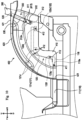
- the reinforcing portion fixing part 422 shown in Fig. 17 is a portion to which a second fixation piece portion 520 of the reinforcing portion 500, which will be described later, is fixed.
- the reinforcing portion fixing part 422 constitutes a rear part of the second portion 420.
- the reinforcing portion fixing part 422 includes fixation holes 422a.
- the fixation holes 422a are used for fixation to the second fixation piece portion 520 of the reinforcing portion 500, which will be described later.
- the fixation holes 422a are opened to penetrate the reinforcing portion fixing part 422 in the vertical direction.
- a pair of fixation holes 422a are formed at a distance in the lateral direction. Appropriate fasteners are inserted through the fixation holes 422a.
- the reinforcing portion 500 shown in Fig. 10 and 17 reinforces the fender 400.
- the reinforcing portion 500 reinforces the fender 400 by connecting the first portion 410 and the second portion 420 of the fender 400.
- the reinforcing portion 500 is provided on the inner surface of the fender 400 (the laterally outer surface of the first portion 410 and the lower surface of the second portion 420).
- the reinforcing portion 500 is provided at a rear part of the fender 400.
- the reinforcing portion 500 includes a first fixation piece portion 510, a second fixation piece portion 520, and a connecting piece portion 530.
- the first fixation piece portion 510 shown in Fig. 17 is fixed to the first portion 410 and the second fixation piece portion 312 of the ROPS 300.
- the first fixation piece portion 510 constitutes a lower-side portion of the reinforcing portion 500.
- the first fixation piece portion 510 is formed in a substantially plate shape whose thickness direction is in the lateral direction.
- the first fixation piece portion 510 is formed in a substantially rectangular shape that is longer in the vertical direction in a side view.
- the first fixation piece portion 510 is provided to contact the laterally outer surface of the first portion 410.
- the first fixation piece portion 510 includes fixation holes 511.
- the fixation holes 511 are used for fixation to the first portion 410 and the second fixation piece portion 312.
- the fixation holes 511 are opened to penetrate the first fixation piece portion 510 in the lateral direction.
- a pair of fixation holes 511 are formed at a distance in the vertical direction.
- the fixation holes 511 are formed to overlap the third fixation holes 413 and the fixation holes 312a of the second fixation piece portion 312 in a side view.
- the shaft portions 21 of fasteners 20 are inserted through the fixation holes 511.
- the second fixation piece portion 520 is fixed to the reinforcing portion fixing part 422 of the second portion 420.
- the second fixation piece portion 520 constitutes an upper-side portion of the reinforcing portion 500.
- the second fixation piece portion 520 is formed in a substantially plate shape whose thickness direction is in the vertical direction.
- the second fixation piece portion 520 is formed in a substantially rectangular shape that is longer in the lateral direction in a plan view.
- the second fixation piece portion 520 is provided to contact the lower surface of the reinforcing portion fixing part 422 of the second portion 420.
- the second fixation piece portion 520 includes fixation holes 521.
- the fixation holes 521 are used for fixation to the reinforcing portion fixing part 422 of the second portion 420.
- the fixation holes 521 are opened to penetrate the second fixation piece portion 520 in the vertical direction.
- a pair of second fixation piece portions 520 are formed at a distance in the lateral direction.
- the fixation holes 521 are formed to overlap the fixation holes 422a of the second portion 420 in a plan view. Appropriate fasteners are inserted through the fixation holes 521.
- the connecting piece portion 530 connects the first fixation piece portion 510 and the second fixation piece portion 520. More specifically, the connecting piece portion 530 connects the upper end portion of the first fixation piece portion 510 and the laterally inner end portion of the second fixation piece portion 520.
- the shaft portions 21 of fasteners 20 are inserted through the fixation holes 511 of the reinforcing portion 500 and the holes 31 of vibration insulating portions 30 attached to the third fixation holes 413 of the fender 400, and the shaft portions 21 are threadedly engaged with the fixation holes 312a of the ROPS 300.
- appropriate cylindrical collars are interposed between the shaft portions 21 of the fasteners 20 and the holes 31 of the vibration insulating portions 30. The fender 400 and the reinforcing portion 500 are thus fixed to the ROPS 300.
- the fender 400 is attached to the step 110, the seat base 120, and the ROPS 300 fixed to the transmission case 4.
- an operator moves the fender 400 forward relative to the step 110 (the first fixation piece portion 117) as shown in Figs. 14 and 15A , and insert the positioning protrusion 117b of the first fixation piece portion 117 through the positioning hole 421b of the fender 400.
- the operator moves the fender 400 downward and places the positioning hole 421b (the fender 400) on the shaft portion 117c of the positioning protrusion 117b (put the inner surface of the positioning hole 421b into contact with the upper surface of the shaft portion 117c) as shown in Figs. 15B and 16 .
- the inner diameter centers of the fixation hole 421a and the fixation hole 117a of the step 110 coincide with each other.
- the fixation holes 118a, 121d, 122d, 123g, and 312a coincide with each other.
- the movement of the fender 400 relative to the step 110 in the radial direction of the positioning protrusion 117b is restricted.
- the fender 400 can be easily positioned with respect to the step 110 and the seat base 120 while the positioning protrusion 117b is inserted through the positioning hole 421b and the fender 400 is placed on the step 110.
- the operator fixes the fender 400 to the tractor body except for the ROPS 300 (the step 110 and the seat base 120) by using appropriate fasteners. More specifically, the operator inserts appropriate fasteners through the fixation holes formed in the fender 400 (the first fixation hole 411, the second fixation holes 412, and the fixation hole 421a) and the fixation holes formed in the step 110 and the seat base 120 (the fixation hole 117a, the fixation hole 118a, the fixation holes 121d, the fixation hole 122d, and the fixation hole 123g) and fastening the fender 400 to the step 110 and the seat base 120 to fix the fender 400 to the above-mentioned tractor body.
- the fixation holes formed in the fender 400 the first fixation hole 411, the second fixation holes 412, and the fixation hole 421a
- the fixation holes formed in the step 110 and the seat base 120 the fixation hole 117a, the fixation hole 118a, the fixation holes 121d,
- the operator may first insert the fasteners through the respective fixation holes and then temporarily fasten the fastener (fastens them so as not to be completely fixed) to temporarily fix the fender 400 to the step 110 and the seat base 120.
- the movement of the fender 400 in the forward-backward direction is restricted by the fasteners inserted through the fixation holes formed in the first portion 410 of the fender 400 (the first fixation hole 411 and the second fixation holes 412) and the fixation holes formed in the step 110 and the seat base 120 (the fixation holes 118a, 121d, 122d, and 123g).
- the operator finally fastens (completely fastens) the above-mentioned fasteners.
- the fender 400 is thus completely fixed to the step 110 and the seat base 120.
- the operator fixes the first portion 410 of the fender 400 and the reinforcing portion 500 to the ROPS 300 by using fasteners 20. More specifically, as shown in Figs. 11 and 17 , the operator attaches vibration insulating portions 30 to the third fixation holes 413 of the fender 400 (the first portion 410) and inserts fasteners 20 through the fixation holes 312a of the ROPS 300 (the second fixation piece portion 312), the third fixation holes 413 of the fender 400 (the holes 31 of the vibration insulating portions 30), and the fixation holes 511 of the reinforcing portion 500 (the first fixation piece portion 510) and fixes the ROPS 300, the fender 400, and the reinforcing portion 500 by joint fastening.
- the ROPS 300, the fender 400, and the reinforcing portion 500 are thus fixed together.
- the operator fixes the second portion 420 of the fender 400 and the reinforcing portion 500 by using appropriate fasteners. More specifically, as shown in Fig. 17 , the operator inserts appropriate fasteners through the fixation holes 422a of the reinforcing portion fixing part 422 of the fender 400 (the second portion 420) and the fixation holes 521 of the reinforcing portion 500 (the second fixation piece portion 520) and fastens the second portion 420 of the fender 400 and the reinforcing portion 500 to fix the fender 400 and the reinforcing portion 500.
- the fender 400 and the reinforcing portion 500 are attached to the tractor body in the above-described manner.
- vibration insulating portions 30 are interposed between the steps 110 and the seat base 120. More specifically, as shown in Figs. 8 and 9 , vibration insulating portions 30 are attached to the fixation holes 123d formed in the lower fixing parts 123c of the seat base 120 (the front wall portion 123) (the insertion portions 32 of the vibration insulating portions 30 are inserted through the fixation holes 123d). In addition, fasteners 20 are inserted through the fixation holes 123d (the holes 31 of the vibration insulating portions 30) and the fourth fixation holes 116 of the steps 110 (the main bodies 111) to fix the steps 110 and the seat base 120.
- the vibration insulating portions 30 (the second increased diameter portions 34) can be interposed between the steps 110 and the seat base 120.
- the transmission of vibration from the fenders 400 to the steps 110 via the seat base 120 can be suppressed.
- vibration insulating portions 30 are also interposed between the step supporting portion 101 (the first step supporting portion 102, the second step supporting portions 103, and the third step supporting portions 104) and the steps 110 in generally the same way as the above-described manner.
- vibration transmitted from the transmission case 4 to the steps 110 can be suppressed.
- vibration insulating portions 30 are also interposed between the seat base supporting portion 105 (the first seat base supporting portion 106 and the second seat base supporting portions 107) and the seat base 120 in generally the same way as the above-described manner.
- vibration transmitted from the transmission case 4 to the seat base 120 and the fenders 400 can be suppressed.
- vibration transmitted from the seat base 120 and the fenders 400 to the steps 110 can be suppressed.
- vibration insulating portions 30 are interposed between the ROPS 300 and the fenders 400 and between the fenders 400 and the reinforcing portion 500. More specifically, as shown in Figs. 11 and 17 , vibration insulating portions 30 are attached to the third fixation holes 413 formed in the fender 400. In addition, fasteners 20 are inserted through the third fixation holes 413 (the holes 31 of the vibration insulating portions 30), the fixation holes 312a of the ROPS 300, and the fixation holes 511 of the reinforcing portion 500 to fix the ROPS 300, the fender 400, and the reinforcing portion 500.
- the vibration insulating portions 30 (the second increased diameter portions 34) can be interposed between the ROPS 300 and the fender 400, and the vibration insulating portions 30 (the first increased diameter portions 33) can be interposed between the fender 400 and the reinforcing portion 500.
- vibration transmitted from the ROPS 300 to the fender 400 and vibration transmitted from the ROPS 300 to the reinforcing portion 500 can be suppressed, and vibration transmitted from the fender 400 to the step 110 can be suppressed.
- the tractor 1 (work vehicle) according to the present embodiment includes:
- the workability of attaching the fender 400 can be improved. That is, by inserting the positioning protrusion 117b through the positioning hole 421b, the fender 400 can be easily positioned with respect to the fixing part (step 110). Thus, the workability of attaching the fender 400 can be improved.
- the positioning protrusion 117b includes: the shaft portion 117c protruding from one of the fender 400 or the fixing part (step 110) in the predetermined direction; and the head portion 117d provided at the tip portion of the shaft portion 117c in the protruding direction for suppressing coming off of the positioning hole 421b from the positioning protrusion 117b.
- the workability of attaching the fender 400 can be better improved. That is, since the head portion 117d is provided, coming off of the fender 400 from the fixing part (step 110) can be suppressed, and the workability of attaching the fender 400 can be better improved.
- the head portion 117d is formed in a shape having a larger diameter than the shaft portion 117c.
- the workability of attaching the fender 400 can be better improved. That is, since the head portion 117d is provided is formed in a shape having a larger diameter than the shaft portion 117c, coming off of the fender 400 from the fixing part (step 110) can be suppressed even when the fender 400 before fixation is displaced in any direction along the radial direction of the head portion 117d, and the workability of attaching the fender 400 can be better improved.
- the fender 400 and the fixing part (step 110) include the fixation holes 117a and 421a used to fix the fender 400 and the fixing part (step 110) to each other, and the inner diameter centers of the fixation hole 421a of the fender 400 and the fixation hole (the fixation hole 117a) of the fixing part (step 110) coincide with each other when one of the positioning protrusion 117b or the positioning hole 421b provided to the fender 400 is placed on the other of the positioning protrusion 117b or the positioning hole 421b provided to the fixing part (step 110).
- the workability of attaching the fender 400 can be better improved. That is, since the inner diameter centers of the fixation holes 117a and 421a of the fender 400 and the fixing part (step 110) coincide with each other when the fender 400 is placed on the fixing part (step 110) via the positioning protrusion 117b and the positioning hole 421b, fixation via a fastener 20 such as a bolt can be performed in this state.
- the fender 400 and the fixing part (step 110) include the fixation holes (fixation holes 117a, 118a, 121d, 122d, 123g, 312a, and 421a, the first fixation hole 411, the second fixation holes 412, the third fixation holes 413) used to fix the fender 400 and the fixing part (step 110) to each other, and the fixation holes include orthogonal holes having an opening direction orthogonal to the opening direction of the positioning hole 421b (the fixation holes 118a, 121d, 122d, 123g, and 312a, the first fixation hole 411, the second fixation holes 412, the third fixation holes 413).
- the workability of attaching the fender 400 can be better improved. That is, when the positioning protrusion 117b is inserted through the positioning hole 421b, the movement of the fender 400 relative to the fixing part (step 110) in the radial direction of the positioning protrusion 117b is restricted, but the movement in the axial direction (inserting direction) of the positioning protrusion 117b is allowed.
- the movement of the fender 400 is restricted in the axial direction as well as in the radial direction, and more effective positioning is enabled.
- the fixing part is the step 110 provided to the driver's seat, and the positioning protrusion 117b is provided to the step 110.
- the workability of attaching the fender 400 can be better improved. That is, since the positioning protrusion 117b is provided to a member having a relatively high stiffness, the fender 400 can be stably supported via the positioning protrusion 117b.
- the tractor 1 (work vehicle) according to the present embodiment includes: the fender 400 covering the rear wheel 7; the seat base 120 to which the fender 400 is fixed and on which the seat 130 is installed; the step 110 that is disposed above or below the seat base 120 and to which the seat base 120 is fixed; and the first vibration insulating portion (vibration insulating portion 30) having a vibration insulating property and interposed between the step 110 and the seat base 120.
- the transmission of vibration from the fender 400 to the step 110 can be suppressed. That is, since the first vibration insulating portion (vibration insulating portion 30) is interposed between the step 110 and the seat base 120, the transmission of vibration from the fender 400 to the step 110 via the seat base 120 can be suppressed.
- the tractor 1 (work vehicle) includes: the ROPS 300 that is disposed beside the fender 400 and to which the fender 400 is fixed; and the second vibration insulating portion (vibration insulating portion 30) having a vibration insulating property and interposed between the ROPS 300 and the fender 400.
- vibration transmitted from the fender 400 to the step 110 can be better suppressed. That is, since the second vibration insulating portion (vibration insulating portion 30) is interposed between the ROPS 300 and the fender 400, vibration in the array direction of the ROPS 300 and the fender 400 (the lateral direction) transmitted from the ROPS 300 to the fender 400 can be suppressed. Thus, vibration transmitted from the fender 400 to the step 110 can be suppressed.
- the fender 400 includes the fixation hole (third fixation hole 413) that is opened in a direction in which the fender 400 and the ROPS 300 are arrayed (lateral direction) and through which a fastener 20 used for fixation to the ROPS 300 is inserted, and the second vibration insulating portion (vibration insulating portion 30) has the hole 31 through which the fastener 20 is inserted and is inserted through the fixation hole (third fixation hole 413).
- vibration transmitted from the fender 400 to the step 110 can be better suppressed. That is, since the second vibration insulating portion (vibration insulating portion 30) is inserted through the fixation hole (third fixation hole 413) and the fastener 20 used to fix the fender 400 and the ROPS 300 to each other is inserted through the second vibration insulating portion (vibration insulating portion 30), vibration in the vertical direction and the forward-backward direction transmitted from the ROPS 300 to the fender 400 can be suppressed. Thus, vibration transmitted from the fender 400 to the step 110 can be suppressed.
- the tractor 1 (work vehicle) includes: the reinforcing portion 500 that reinforces the fender 400; and the third vibration insulating portion (vibration insulating portion 30) having a vibration insulating property and interposed between the reinforcing portion and the ROPS.
- vibration transmitted from the fender 400 to the step 110 can be better suppressed. That is, by enhancing the stiffness of the fender 400 by the reinforcing portion 500, vibration of the fender 400 can be suppressed.
- vibration insulating portion 30 is interposed between the reinforcing portion 500 and the ROPS 300, vibration transmitted from the ROPS 300 to the reinforcing portion 500 can be suppressed.
- vibration transmitted from the fender 400 to the step 110 can be suppressed.
- the third vibration insulating portion (vibration insulating portion 30) is used in common with the second vibration insulating portion (vibration insulating portion 30).
- the fender 400 includes the first portion 410 fixed to the ROPS 300; and the second portion 420 covering a radially outer portion of the rear wheel 7; and the reinforcing portion 500 connects the first portion 410 and the second portion 420.
- vibration transmitted from the fender 400 to the step 110 can be better suppressed. That is, since the first portion 410 and the second portion 420 of the fender is connected by the reinforcing portion 500, the stiffness of the fender 400 can be effectively enhanced. Thus, vibration of the fender 400 can be suppressed, and vibration transmitted from the fender 400 to the step 110 can be suppressed.
- the fender 400 includes the fixing part (first fixation piece portion 117) fixed to the step 110 while contacting the step 110.
- the transmission of vibration from the fender 400 to the step 110 can be suppressed while securely fixing the fender 400 to the step 110. That is, the fender 400 can be securely fixed to the step 110 at the fixing part (first fixation piece portion 117), and at the other portion, the fixation to the step 110 is made by interposing the first vibration insulating portion (vibration insulating portion 30) and thus the vibration can be suppressed.
- tractor 1 (work vehicle) includes:
- vibration of the step 110 can be better suppressed.
- vibration insulating portion 30 vibration insulating portion 30
- the fourth vibration insulating portion is interposed between the first supporting portion (step supporting portion 101) provided to the mission case (transmission case 4) and the step 110, vibration transmitted from the mission case (transmission case 4) to the step 110 can be suppressed.
- tractor 1 (work vehicle) includes:
- vibration of the step 110 can be better suppressed. That is, since the fifth vibration insulating portion (vibration insulating portion 30) is interposed between the second supporting portion (seat base supporting portion 105) provided to the mission case (transmission case 4) and the seat base 120, vibration transmitted from the mission case (seat base supporting portion 105) to the seat base 120 and the fender 400 can be suppressed. Thus, vibration transmitted from the seat base 120 and the fenders 400 to the steps 110 can be suppressed.
- tractor 1 is a form of embodying the work vehicle.
- the transmission case 4 is a form of embodying the mission case.
- the vibration insulating portions 30 are a form of embodying the first vibration insulating portion, the second vibration insulating portion, the third vibration insulating portion, the fourth vibration insulating portion, and the fifth vibration insulating portion.
- step supporting portion 101 is a form of embodying the first supporting portion.
- the seat base supporting portion 105 is a form of embodying the second supporting portion.
- step 110 according to the present embodiment is a form of the fixing part.
- the first fixation piece portion 117 is a form of embodying the fixing part.
- the present embodiment shows a configuration in which the positioning protrusion 117b is provided to the step 110, there is no limitation thereto.
- the positioning protrusion 117b may be provided to any member on the tractor body side such as the seat base 120 or the ROPS 300.
- the present embodiment shows a configuration in which the positioning hole 421b is provided to the fender 400 and the positioning protrusion 117b is provided to the step 110, there is no limitation thereto.
- a configuration in which the positioning protrusion 117b is provided to the fender 400 and the positioning hole 421b is provided to the step 110 may be used.
- the portions at which the fender 400 is fixed to the tractor body are not limited to the above-mentioned ones, and any fixing parts may be used.
- fasteners 20 are composed of bolts
- fasteners 20 capable of fixing a plurality of members such as rivets
- fasteners 20 may be used as the fasteners 20.
- the vibration insulating portions 30 are formed of a material having flexibility, there is no limitation thereto. Various materials and structures having a vibration insulating property may be used for the vibration insulating portions 30.
- the present embodiment shows a configuration in which the fender 400 is fixed to the first fixation piece portion 117 while contacting the first fixation piece portion 117 of the step 110, there is no limitation thereto.
- a vibration insulating portion 30 may be interposed between the first fixation piece portion 117 and the fender 400.
- the present embodiment shows a configuration in which a plurality of vibration insulating portions 30 are interposed between the step supporting portion 101 (the first step supporting portion 102, the second step supporting portions 103, and the third step supporting portions 104) and the steps 110, there is no limitation thereto.
- some or all of the plurality of vibration insulating portions 30 may not be provided.
- the present embodiment shows a configuration in which a plurality of vibration insulating portions 30 are interposed between the seat base supporting portion 105 (the first seat base supporting portion 106 and the second seat base supporting portions 107) and the seat base 120, there is no limitation thereto. For example, some or all of the plurality of vibration insulating portions 30 may not be provided.
- the present embodiment shows a configuration in which the vibration insulating portions 30 interposed between the ROPS 300 and the fender 400 and the vibration insulating portions 30 interposed between the reinforcing portion 500 and the ROPS 300 are used in common, there is no limitation thereto.
- the vibration insulating portions 30 interposed between the ROPS 300 and the fender 400 and the vibration insulating portion 30 interposed between the reinforcing portion 500 and the ROPS 300 may be individually provided.
- the present embodiment shows a configuration in which the reinforcing portion 500 is provided to the fender 400, there is no limitation thereto.
- the reinforcing portion 500 may not be provided.
- the tractor 1 is illustrated as an example of the work vehicle in the above-described embodiment, there is no limitation thereto.
- the work vehicle may be another agricultural vehicle, construction vehicle, industrial vehicle, or the like.
Landscapes
- Engineering & Computer Science (AREA)
- Mechanical Engineering (AREA)
- Chemical & Material Sciences (AREA)
- Combustion & Propulsion (AREA)
- Transportation (AREA)
- Body Structure For Vehicles (AREA)
Description
- The disclosure relates to a technique of a work vehicle.
- Conventionally, a technique of a work vehicle such as a tractor having a step and a fender has been known. An example is disclosed in
JP 2006-117148 A JP 2006-117148 A - The document
EP 3 470 583 A2 describes support member that supports a driver's seat, disposed in a rear portion of a machine body, and left and right rear-wheel fenders disposed at left and right lateral portions of the support member. A control unit is supported between the left and right fenders, and at a lower side of a rear portion of a rear side of the driver's seat in the support member. - In the document
WO 2016 / 189940 A1 , a tractor is disclosed, wherein hot-air blocking plates, each of which is interposed between a prime mover unit and a driving unit, have a common basic shape and serve as sharable elements, thereby accommodating the various types of specifications of the prime mover units and the driving units having different sizes by cutting the outer edges of the hot-air blocking plates. - The document
KR 2015 0145034 A - It is an object to provide a work vehicle that can suppress vibration transmitted from a fender to a step.
- The problem to be solved by a work vehicle of
claim 1. Further embodiments are disclosed in the dependent claims. - The fender may comprise a fixation hole that is opened in a direction in which the fender and the ROPS are arrayed and through which a fastener used for fixation to the ROPS is inserted, and the second vibration insulating portion may have a hole through which the fastener is inserted and is inserted through the fixation hole.
- The work vehicle may comprise a reinforcing portion that reinforces the fender; and a third vibration insulating portion having a vibration insulating property and interposed between the reinforcing portion and the ROPS.
- The third vibration insulating portion may be used in common with the second vibration insulating portion.
- In the work vehicle, the fender may comprise a first portion fixed to the ROPS, and a second portion covering a radially outer portion of the rear wheel, and the reinforcing portion may connect the first portion and the second portion.
- The fender may comprise a fixing part fixed to the step while contacting the step.
- The work vehicle may comprise a mission case containing a power transmission mechanism; a first supporting portion that is provided to the mission case and supports the step from below and to which the step is fixed; and a fourth vibration insulating portion having a vibration insulating property and interposed between the first supporting portion and the step.
- The work vehicle may further comprise a mission case containing a power transmission mechanism; a second supporting portion that is provided to the mission case and supports the seat base from below and to which the seat base is fixed; and a fifth vibration insulating portion having a vibration insulating property and interposed between the second supporting portion and the seat base.
- One or more of the following effects may obtained as effects of the disclosure.
- In the work vehicle, vibration transmitted from the fender to the step can be suppressed.
- In the work vehicle, vibration transmitted from the fender to the step can be better suppressed.
- In the work vehicle, vibration transmitted from the fender to the step can be better suppressed.
- In the work vehicle, vibration transmitted from the fender to the step can be better suppressed.
- In the work vehicle, using the third vibration insulating portion in common with the second vibration insulating portion can suppress increase in the number of members.
- In the work vehicle, vibration transmitted from the fender to the step can be better suppressed.
- In the work vehicle, transmission of vibration from the fender to the step can be suppressed while securely fixing the fender to the step.
- In the work vehicle, vibration of the step can be better suppressed.
- In the work vehicle, vibration of the step can be better suppressed.
- Following, further embodiments are described by reference to figures. In the Figures show:
- Fig. 1
- a side view showing an overall configuration of a tractor according to an embodiment of the disclosure;
- Fig. 2
- a plan view showing a driver's seat;
- Fig. 3
- a perspective view showing the driver's seat;
- Fig. 4
- an exploded perspective view showing steps and a step supporting portion;
- Fig. 5
- an enlarged exploded perspective view showing a step and the step supporting portion;
- Fig. 6
- an exploded perspective view showing a seat base and a seat base supporting portion;
- Fig. 7
- an enlarged exploded perspective view showing the seat base and the seat base supporting portion;
- Fig. 8
- an enlarged exploded perspective view showing the seat base and the steps;
- Fig. 9
- a side cross-sectional view showing how the seat base and the step are fixed;
- Fig. 10
- a side view showing the driver's seat and a fender;
- Fig. 11
- a side cross-sectional view showing how a ROPS, the fender, and a reinforcing portion are fixed;
- Fig. 12
- a rear perspective view showing the driver's seat and the fender;
- Fig. 13
- a rear exploded perspective view showing the driver's seat and the fender;
- Fig. 14
- an enlarged exploded perspective view showing the step and the fender;
- Fig. 15A
- a rear view showing the state where a positioning protrusion is inserted through a positioning hole;
- Fig. 15B
- is a rear view showing the state where the positioning hole is placed on the positioning protrusion;
- Fig. 16
- an enlarged perspective view showing the step and the fender; and
- Fig. 17
- an exploded perspective view showing the ROPS, the fender, and the reinforcing portion.
- In the following description, the directions indicated by arrow U, arrow D, arrow F, arrow B, arrow L, and arrow R are defined as an upward direction, a downward direction, a forward direction, a backward direction, a leftward direction, and a rightward direction, respectively.
- The following will describe an entire configuration of a
tractor 1 according to an embodiment of the disclosure with reference toFig. 1 . - The
tractor 1 mainly includes a body frame 2, an engine 3, atransmission case 4, ahydraulic elevator 5, front wheels 6,rear wheels 7, a hood 8, a ridingportion 100, aROPS 300,fenders 400, a reinforcing portion 500 (seeFig. 10 ), and the like. - The body frame 2 is disposed such that its longitudinal direction is in the forward-backward direction. The engine 3 is fixed to a rear portion of the body frame 2. The
transmission case 4 is disposed behind the engine 3. Thehydraulic elevator 5 is provided to a rear portion of thetransmission case 4. Various working devices (such as a rotary tiller) can be mounted to thehydraulic elevator 5. Also, various working machines (such as a mower) can be mounted to a lower portion of the transmission case 4 (between the front wheels 6 and the rear wheels 7). - The
transmission case 4 contains a power transmission mechanism (not shown) such as a transmission. Aclutch housing 4a is provided forward of the transmission case 4 (between thetransmission case 4 and the engine 3) (seeFig. 3 ). Thehydraulic elevator 5 is fixed to a rear portion of thetransmission case 4 and includes ahydraulic case 5a containing a hydraulic cylinder (seeFig. 6 ). - A front portion of the body frame 2 is supported by the pair of left and right front wheels 6 via a front axle mechanism (not shown). The
transmission case 4 is supported by the pair of left and rightrear wheels 7 via a rear axle mechanism (not shown). The pair of left and rightrear wheels 7 are covered by thefenders 400 from generally above. - In addition, the engine 3 is covered by the hood 8. The riding
portion 100, on which a driver rides, is provided behind the hood 8. TheROPS 300 for protecting the ridingportion 100 is provided behind the ridingportion 100. - Power of the engine 3 is subjected to a speed conversion at the transmission (not shown) contained in the
transmission case 4 and is then made transmittable to the front wheels 6 via the front axle mechanism and made transmittable to therear wheels 7 via the rear axle mechanism. Thus, the front wheels 6 and therear wheels 7 are rotationally driven by the power of the engine 3, so that thetractor 1 can travel. - The
transmission case 4, the riding portion 100 (steps 110 and aseat base 120, which will be described later), theROPS 300, and thefenders 400 as described above are fixed to each other by usingfasteners 20 shown inFigs. 4 ,5 , and17 .Vibration insulating portions 30 are interposed at the fixing parts where thefasteners 20 are used. The following will describe thefasteners 20 and thevibration insulating portions 30 in detail with reference toFigs. 4 ,9 , and11 . - The
fasteners 20 shown inFigs. 4 ,9 , and11 can fix a plurality of members by being inserted through appropriate fixation holes (such as afixation hole 123d shown inFig. 9 ). Eachfastener 20 is composed of a bolt capable of fastening a plurality of members. Various bolts such as hexagon head bolts or weld bolts may be used as thefasteners 20. Eachfastener 20 includes ashaft portion 21 and ahead portion 22. - The
shaft portion 21 is a portion inserted through a fixation hole. An appropriate male screw portion is formed in theshaft portion 21. - The
head portion 22 is a portion having a larger diameter than theshaft portion 21. - The
vibration insulating portions 30 shown inFigs. 4 ,9 , and11 have a vibration insulating property. Thevibration insulating portions 30 are formed in a substantially cylindrical shape. Thevibration insulating portions 30 are formed of a material having flexibility such as rubber. Thevibration insulating portions 30 are attached to (inserted through) fixation holes (such as thefixation hole 123d shown inFig. 9 ) through which thefasteners 20 are inserted. Eachvibration insulating portion 30 includes ahole 31, aninsertion portion 32, a first increaseddiameter portion 33, and a second increaseddiameter portion 34. - The
hole 31 is a portion through which theshaft portion 21 of thefastener 20 is inserted. Thehole 31 is formed to penetrate thevibration insulating portion 30 in the axial direction (the inserting direction of the fastener 20). - The
insertion portion 32 is a portion inserted through the fixation hole to which thevibration insulating portion 30 is attached. Theinsertion portion 32 constitutes an axially central portion of thevibration insulating portion 30. - The first increased
diameter portion 33 is a portion constituting one side of thevibration insulating portion 30 in the axial direction (the side on which thehead portion 22 of thefastener 20 is located). The first increaseddiameter portion 33 has a larger diameter than theinsertion portion 32. - The second increased
diameter portion 34 is a portion constituting the other side of thevibration insulating portion 30 in the axial direction (the side opposite to thehead portion 22 in the axial direction). The second increaseddiameter portion 34 has a larger diameter than theinsertion portion 32. The second increaseddiameter portion 34 is formed in a shape whose end portion on the other side in the axial direction gradually decreases in diameter toward its tip. - Next, the riding
portion 100 will be described in detail with reference toFigs. 1 to 9 . As shown inFig. 1 , a steering wheel 9 for adjusting the steering angle of the front wheels 6 is disposed at a front portion of the ridingportion 100. Various pedals are disposed on the floor portion of the riding portion 100 (steps 110, which will be described later). The ridingportion 100 includes astep supporting portion 101, a seatbase supporting portion 105,steps 110, aseat base 120, and aseat 130. - The
step supporting portion 101 shown inFigs. 4 and5 supports thesteps 110, which will be described later, from below. Thestep supporting portion 101 is provided to thetransmission case 4. - The
step supporting portion 101 includes a firststep supporting portion 102, secondstep supporting portions 103, and thirdstep supporting portions 104. - The first
step supporting portion 102 supports front parts of thesteps 110, which will be described later. The firststep supporting portion 102 is formed to be longer in the lateral direction. The firststep supporting portion 102 is formed to extend toward both lateral sides of the transmission case 4 (theclutch housing 4a). The firststep supporting portion 102 is formed by appropriately combining a plate-shaped member whose thickness direction is in the forward-backward direction and a plate-shaped member whose thickness direction is in the vertical direction. The firststep supporting portion 102 is provided on the upper surface of theclutch housing 4a. That is, the firststep supporting portion 102 is provided to thetransmission case 4 via theclutch housing 4a. The firststep supporting portion 102 includesfixation holes 102a. - The
fixation holes 102a shown inFigs. 4 and5 are used to fix the front parts of thesteps 110, which will be described later. Thefixation holes 102a are opened to penetrate the firststep supporting portion 102 in the vertical direction. Thefixation holes 102a are formed at respective ones of both lateral end portions of the firststep supporting portion 102. A vibration insulating portion 30 (insertion portion 32) is inserted through eachfixation hole 102a. The inner diameter of thefixation hole 102a is formed to be larger than the outer diameter of theinsertion portion 32 of thevibration insulating portion 30 and is formed to be smaller than the outer diameter of the first increaseddiameter portion 33 and the second increaseddiameter portion 34 of thevibration insulating portion 30. - The second
step supporting portions 103 shown inFigs. 4 and5 support forward-backward middle portions of thesteps 110, which will be described later. The secondstep supporting portions 103 are formed to be longer in the forward-backward direction. A pair of secondstep supporting portions 103 are provided to be located on the left and right sides of thetransmission case 4. The secondstep supporting portions 103 are provided on side surfaces of a front part of thetransmission case 4. Each secondstep supporting portion 103 includesfixation holes 103a. - The
fixation holes 103a shown inFigs. 4 and5 are used to fix the forward-backward middle portions of thesteps 110, which will be described later. Thefixation holes 103a are opened to penetrate the secondstep supporting portion 103 in the vertical direction. A pair offixation holes 103a are formed at a distance in the forward-backward direction in each secondstep supporting portion 103. Eachfixation hole 103a has formed therein a female screw portion for threaded engagement with the male screw portion provided to theshaft portion 21 of thefastener 20. - The third
step supporting portions 104 support rear parts of thesteps 110, which will be described later. The thirdstep supporting portions 104 are formed to be longer in the lateral direction. A pair of thirdstep supporting portions 104 are provided to be located on the left and right sides of thetransmission case 4. The thirdstep supporting portions 104 are provided on side surfaces of a rear part of thetransmission case 4. Each thirdstep supporting portion 104 includesfixation holes 104a. - The
fixation holes 104a are used to fix the rear parts of thesteps 110, which will be described later. Thefixation holes 104a are opened to penetrate the thirdstep supporting portion 104 in the vertical direction. A pair offixation holes 104a are formed at a distance in the lateral direction in each thirdstep supporting portion 104. Eachfixation hole 104a has formed therein a female screw portion for threaded engagement with the male screw portion provided to theshaft portion 21 of thefastener 20. - The seat
base supporting portion 105 shown inFigs. 6 and7 supports theseat base 120, which will be described later, from below. The seatbase supporting portion 105 is provided on thehydraulic case 5a. That is, the seatbase supporting portion 105 is provided to thetransmission case 4 via thehydraulic case 5a. The seatbase supporting portion 105 includes a first seatbase supporting portion 106 and second seatbase supporting portions 107. - The first seat
base supporting portion 106 shown inFigs. 6 and7 supports a front part (first fixation frame 121) of theseat base 120, which will be described later. The first seatbase supporting portion 106 is formed to be longer in the lateral direction. The first seatbase supporting portion 106 is provided at a front part of thehydraulic case 5a. The first seatbase supporting portion 106 includesfixation holes 106a. - The
fixation holes 106a are used to fix the front part (first fixation frame 121) of theseat base 120, which will be described later. Thefixation holes 106a are opened to penetrate the first seatbase supporting portion 106 in the vertical direction. A pair offixation holes 106a are formed at a distance in the lateral direction. Eachfixation hole 106a has formed therein a female screw portion for threaded engagement with the male screw portion provided to theshaft portion 21 of thefastener 20. - The second seat
base supporting portions 107 shown inFigs. 6 and7 support a rear part (second fixation frame 122) of theseat base 120, which will be described later. A pair of second seatbase supporting portions 107 are provided to be located on the left and right sides of thehydraulic case 5a. The second seatbase supporting portions 107 are provided at a rear part of thehydraulic case 5a. Each second seatbase supporting portion 107 includes afixation hole 107a. - The
fixation hole 107a is used to fix the rear part (second fixation frame 122) of theseat base 120, which will be described later. Thefixation hole 107a is opened to penetrate the second seatbase supporting portion 107 in the vertical direction. Thefixation hole 107a has formed therein a female screw portion for threaded engagement with the male screw portion provided to theshaft portion 21 of thefastener 20. - The
steps 110 shown inFigs. 2 ,4 , and5 constitute the floor portion of the ridingportion 100. A pair ofsteps 110 are provided on the left and right sides of thetransmission case 4. The pair ofsteps 110 are formed to be generally symmetrical in the lateral direction. Eachstep 110 includes amain body 111, positioning holes 112, afirst fixation hole 113, second fixation holes 114, third fixation holes 115, afourth fixation hole 116, a firstfixation piece portion 117, and a secondfixation piece portion 118. - The
main body 111 is a main structural body of thestep 110. Themain body 111 is formed in a substantially plate shape whose thickness direction is in the vertical direction. Themain body 111 is formed in a substantially rectangular shape in a plan view (as seen in the thickness direction) as shown inFig. 2 . Themain body 111 is formed in a shape that is appropriately bent such that its front part is inclined upward. Themain body 111 is supported by thestep supporting portion 101 from below and fixed to thestep supporting portion 101. Themain body 111 includes anotch portion 111a. - The
notch portions 111a shown inFig. 2 are formed by notching parts of themain bodies 111. Thenotch portions 111a are formed at a rear portion of laterally outer portions of themain bodies 111 in a plan view. Thenotch portions 111a are formed in a shape that can receive the left andright fenders 400. - Positioning protrusions (not shown) formed in a floor mat (not shown) laid on the upper surface of the
steps 110 are inserted through the positioning holes 112 shown inFig. 2 . A plurality ofpositioning holes 112 are formed to penetrate themain bodies 111 in the thickness direction. Note that the positioning holes 112 are omitted as appropriate in the figures other thanFig. 2 . - The
first fixation hole 113 shown inFigs. 4 and5 is used for fixation to the firststep supporting portion 102. Thefirst fixation hole 113 is opened to penetrate themain body 111 in the vertical direction. Thefirst fixation hole 113 is formed at a front part of themain body 111. - The
first fixation hole 113 overlaps afixation hole 102a of the firststep supporting portion 102 in a plan view. - The second fixation holes 114 shown in
Figs. 4 and5 are used for fixation to the secondstep supporting portion 103. The second fixation holes 114 are opened to penetrate themain body 111 in the vertical direction. The second fixation holes 114 are formed at a forward-backward middle portion of themain body 111. A pair of second fixation holes 114 are formed at a distance in the forward-backward direction. The second fixation holes 114 overlap thefixation holes 103a of the secondstep supporting portion 103 in a plan view. Avibration insulating portion 30 is inserted through eachsecond fixation hole 114. The inner diameter of thesecond fixation hole 114 is formed to be larger than the outer diameter of theinsertion portion 32 of thevibration insulating portion 30 and is formed to be smaller than the outer diameter of the first increaseddiameter portion 33 and the second increaseddiameter portion 34 of thevibration insulating portion 30. - The third fixation holes 115 shown in
Figs. 4 and5 are used for fixation to the thirdstep supporting portion 104. The third fixation holes 115 are opened to penetrate themain body 111 in the vertical direction. The third fixation holes 115 are formed at a rear part of themain body 111. A pair of third fixation holes 115 are formed at a distance in the lateral direction. The third fixation holes 115 overlap thefixation holes 104a of the thirdstep supporting portion 104 in a plan view. Avibration insulating portion 30 is inserted through eachthird fixation hole 115. The inner diameter of thethird fixation hole 115 is formed to be larger than the outer diameter of theinsertion portion 32 of thevibration insulating portion 30 and is formed to be smaller than the outer diameter of the first increaseddiameter portion 33 and the second increaseddiameter portion 34 of thevibration insulating portion 30. - The
fourth fixation hole 116 shown inFigs. 5 and8 is used to fix the seat base 120 (a front wall portion 123), which will be described later. Thefourth fixation hole 116 is opened to penetrate themain body 111 in the vertical direction. Thefourth fixation hole 116 is formed forward of the third fixation holes 115 at a rear part of themain body 111. Thefourth fixation hole 116 has formed therein a female screw portion for threaded engagement with the male screw portion provided to theshaft portion 21 of thefastener 20. - The first
fixation piece portion 117 shown inFigs. 13 and14 is a portion for fixing a front part of thefender 400 at a portion of thenotch portion 111a facing backward. The firstfixation piece portion 117 is formed to extend downward from the portion of thenotch portion 111a facing backward. The firstfixation piece portion 117 is formed in a substantially plate shape whose thickness direction is in the forward-backward direction. The firstfixation piece portion 117 is formed in a rectangular shape in a rear view. The firstfixation piece portion 117 includes afixation hole 117a and apositioning protrusion 117b. - The
fixation hole 117a shown inFig. 14 is used to fix a front part of thefender 400. Thefixation hole 117a is opened to penetrate the firstfixation piece portion 117 in the forward-backward direction. An appropriate fastener is inserted through thefixation hole 117a. - The
positioning protrusion 117b is used to position thefender 400. Thepositioning protrusion 117b protrudes backward from the rear surface of the firstfixation piece portion 117. Thepositioning protrusion 117b is provided on the inner side relative to thefixation hole 117a in the lateral direction. Thepositioning protrusion 117b includes ashaft portion 117c and ahead portion 117d. - The
shaft portion 117c is a portion protruding from the rear surface of the firstfixation piece portion 117. Theshaft portion 117c is formed in a substantially columnar shape whose axial direction is in the forward-backward direction. - The
head portion 117d is a portion provided at the tip of theshaft portion 117c. Thehead portion 117d is formed in a shape having a larger diameter than theshaft portion 117c. Thehead portion 117d is formed in a substantially disc shape whose thickness direction is in the axial direction. - The second
fixation piece portion 118 shown inFigs. 5 and13 is a portion for fixing a side portion of thefender 400 at a portion of thenotch portion 111a facing sideward. The secondfixation piece portion 118 is formed to extend downward from the portion of thenotch portion 111a facing sideward. The secondfixation piece portion 118 is formed in a substantially plate shape whose thickness direction is in the lateral direction. The secondfixation piece portion 118 is formed in a rectangular shape in a side view. The secondfixation piece portion 118 includes afixation hole 118a. - The
fixation hole 118a is used to fix the side portion of thefender 400. Thefixation hole 118a is opened to penetrate the secondfixation piece portion 118 in the lateral direction. An appropriate fastener is inserted through thefixation hole 118a. - The following will describe the manner of fixing the
step supporting portion 101 and thesteps 110 to each other with reference toFigs. 4 and5 . - As shown in
Figs. 4 and5 , theshaft portions 21 offasteners 20 are inserted through the first fixation holes 113 of thesteps 110 and theholes 31 ofvibration insulating portions 30 attached to thefixation holes 102a of the firststep supporting portions 102, and appropriate nuts located below the firststep supporting portion 102 are threadedly engaged with theshaft portions 21. Note that appropriate cylindrical collars are interposed between theshaft portions 21 of thefasteners 20 and theholes 31 of thevibration insulating portions 30. - In addition, the
shaft portions 21 offasteners 20 are inserted through theholes 31 ofvibration insulating portions 30 attached to the second fixation holes 114 of thesteps 110, and theshaft portions 21 are threadedly engaged with thefixation holes 103a of the secondstep supporting portions 103. In addition, theshaft portions 21 offasteners 20 are inserted through theholes 31 ofvibration insulating portions 30 attached to the third fixation holes 115 of thesteps 110, and theshaft portions 21 are threadedly engaged with thefixation holes 104a of the thirdstep supporting portions 104. Thesteps 110 are thus fixed to thestep supporting portion 101. - The
seat 130, which will be described later, is installed on theseat base 120 shown inFigs. 3 and6 to 8 . Theseat base 120 is provided behind thesteps 110 in the ridingportion 100. Theseat base 120 is formed such that its upper surface (the upper surface of a placingpart 124, which will be described later) is located above the upper surface of themain bodies 111 of thesteps 110. In other words, theseat base 120 is formed at a greater height than themain bodies 111 of thesteps 110. Theseat base 120 includes afirst fixation frame 121, asecond fixation frame 122, afront wall portion 123, and a placingpart 124. - The
first fixation frame 121 shown inFigs. 6 to 8 is fixed to the first seatbase supporting portion 106. Thefenders 400 are fixed to thefirst fixation frame 121. Thefirst fixation frame 121 includes amain body 121a andfender fixing parts 121c. - The
main body 121a is a main structural body of thefirst fixation frame 121. Themain body 121a is formed to be longer in the lateral direction. Themain body 121a includesfixation holes 121b. - The fixation holes 121b are used for fixation to the first seat
base supporting portion 106. The fixation holes 121b are opened to penetrate themain body 121a in the vertical direction. A pair offixation holes 121b are formed at a distance in the lateral direction. The fixation holes 121b overlap thefixation holes 106a of the first seatbase supporting portion 106 in a plan view. Avibration insulating portion 30 is inserted through eachfixation hole 121b. The inner diameter of thefixation hole 121b is formed to be larger than the outer diameter of theinsertion portion 32 of thevibration insulating portion 30 and is formed to be smaller than the outer diameter of the first increaseddiameter portion 33 and the second increaseddiameter portion 34 of thevibration insulating portion 30. - The
fender fixing parts 121c are portions to which side portions of thefenders 400 are fixed. Thefender fixing parts 121c are formed in a substantially plate shape whose thickness direction is in the lateral direction. Thefender fixing parts 121c are provided at respective ones of both lateral end portions of themain body 121a. Eachfender fixing part 121c includesfixation holes 121d. - The fixation holes 121d are used to fix the side portion of the
fender 400. The fixation holes 121d are opened to penetrate thefender fixing part 121c in the lateral direction. A pair offixation holes 121d are formed at a distance in the forward-backward direction. Appropriate fasteners are inserted through thefixation holes 121d. - The
second fixation frame 122 shown inFigs. 6 to 8 is fixed to the second seatbase supporting portion 107. Thefenders 400 are fixed to thesecond fixation frame 122. Thesecond fixation frame 122 includes amain body 122a andfender fixing parts 122c. - The
main body 122a is a main structural body of thesecond fixation frame 122. Themain body 122a is formed to be longer in the lateral direction. Themain body 122a includesfixation holes 122b. - The fixation holes 122b are used for fixation to the second seat
base supporting portion 107. The fixation holes 122b are opened to penetrate themain body 122a in the vertical direction. A pair offixation holes 122b are formed at a distance in the lateral direction. The fixation holes 122b overlap thefixation holes 107a of the second seatbase supporting portion 107 in a plan view. Avibration insulating portion 30 is inserted through eachfixation hole 122b. The inner diameter of thefixation hole 122b is formed to be larger than the outer diameter of theinsertion portion 32 of thevibration insulating portion 30 and is formed to be smaller than the outer diameter of the first increaseddiameter portion 33 and the second increaseddiameter portion 34 of thevibration insulating portion 30. - The
fender fixing parts 122c are portions to which side portions of thefenders 400 are fixed. Thefender fixing parts 122c are formed in a substantially plate shape whose thickness direction is in the lateral direction. Thefender fixing parts 122c are provided at respective ones of both lateral end portions of themain body 122a. Eachfender fixing part 122c includes afixation hole 122d. - The
fixation hole 122d is used to fix the side portion of thefender 400. Thefixation hole 122d is opened to penetrate thefender fixing part 122c in the lateral direction. An appropriate fastener is inserted through thefixation hole 122d. - The
front wall portion 123 shown inFigs. 6 ,8 , and9 constitutes the front surface of theseat base 120. Thefront wall portion 123 is disposed to bridge between the pair ofsteps 110. Thefront wall portion 123 is disposed above the steps 110 (the main bodies 111). Thefront wall portion 123 is fixed to the rear end portions of the steps 110 (the main bodies 111) and thefirst fixation frame 121. Thefront wall portion 123 includes amain body 123a, lower fixingparts 123c, anupper fixing part 123e, andfender fixing parts 123f. - The
main body 123a shown inFigs. 6 and8 is a main structural body of thefront wall portion 123. Themain body 123a is formed in a substantially plate shape whose thickness direction is in the forward-backward direction. Themain body 123a includes arecess 123b. - The
recess 123b opens downward to receive an upper portion of thetransmission case 4. Therecess 123b is formed at a laterally central portion of the lower end of themain body 123a. - The
lower fixing parts 123c shown inFigs. 8 and9 are portions fixed to the rear end portions of themain bodies 111 of thesteps 110. Thelower fixing parts 123c are formed to protrude forward from the lower end of themain body 123a. Thelower fixing parts 123c are formed in a substantially plate shape whose thickness direction is in the vertical direction. A pair of lower fixingparts 123c are provided to be located on both the left and right sides of therecess 123b. Eachlower fixing part 123c includes afixation hole 123d. - The fixation holes 123d are used for fixation to the
main bodies 111 of thesteps 110. The fixation holes 123d are opened to penetrate thelower fixing parts 123c in the vertical direction. The fixation holes 123d overlap the fourth fixation holes 116 of thesteps 110 in a plan view. As shown inFig. 9 , avibration insulating portion 30 is inserted through eachfixation hole 123d. The inner diameter of thefixation hole 123d is formed to be larger than the outer diameter of theinsertion portion 32 of thevibration insulating portion 30 and is formed to be smaller than the outer diameter of the first increaseddiameter portion 33 and the second increaseddiameter portion 34 of thevibration insulating portion 30. - The
upper fixing part 123e shown inFigs. 6 and8 is a portion fixed to thefirst fixation frame 121. Theupper fixing part 123e is formed to protrude backward from the upper end portion of themain body 123a. Theupper fixing part 123e is formed in a substantially plate shape whose thickness direction is in the vertical direction. Theupper fixing part 123e is placed on the upper surface of thefirst fixation frame 121. Theupper fixing part 123e has formed therein an appropriate hole opened to penetrate theupper fixing part 123e in the vertical direction and used for fixation to thefirst fixation frame 121. - The
fender fixing parts 123f shown inFig. 8 are portions to which side portions of thefenders 400 are fixed. Thefender fixing parts 123f are formed to protrude backward from laterally outer end portions of a lower-side portion of themain body 123a. Thefender fixing parts 123f are formed in a substantially plate shape whose thickness direction is in the lateral direction. Thefender fixing parts 123f are provided at respective ones of both lateral end portions of themain body 123a. Eachfender fixing part 123f includes a fixation holes 123g. - The
fixation hole 123g is used to fix the side portion of thefender 400. Thefixation hole 123g is opened to penetrate thefender fixing part 123f in the lateral direction. An appropriate fastener is inserted through thefixation hole 123g. - The placing
part 124 shown inFigs. 3 and6 constitutes the upper surface of theseat base 120. The placingpart 124 is formed in a substantially plate shape whose thickness direction is in the vertical direction. As shown inFig. 6 , the placingpart 124 is disposed to bridge between theupper fixing part 123e of the front wall portion 123 (the first fixation frame 121) and thesecond fixation frame 122. The placingpart 124 has formed therein appropriate holes opened to penetrate the placingpart 124 in the vertical direction. The placingpart 124 is fixed to theupper fixing part 123e (the first fixation frame 121) and thesecond fixation frame 122 using fasteners inserted through the above-mentioned holes. - The following will describe the manner of fixing the seat
base supporting portion 105 and theseat base 120 to each other and the manner of fixing thesteps 110 and theseat base 120 to each other with reference toFigs. 6 to 9 . - As shown in
Figs. 6 and7 , theshaft portions 21 offasteners 20 are inserted through theholes 31 ofvibration insulating portions 30 attached to the fixation holes 121b of thefirst fixation frame 121, and theshaft portions 21 are threadedly engaged with thefixation holes 106a of the first seatbase supporting portion 106. In addition, theshaft portions 21 offasteners 20 are inserted through theholes 31 ofvibration insulating portions 30 attached to the fixation holes 122b of thesecond fixation frame 122, and theshaft portions 21 are threadedly engaged with thefixation holes 107a of the second seatbase supporting portions 107. Thefirst fixation frame 121 and thesecond fixation frame 122 are thus fixed to the seatbase supporting portion 105. - In addition, as shown in
Figs. 8 and9 , theshaft portions 21 offasteners 20 are inserted through theholes 31 ofvibration insulating portions 30 attached to the fixation holes 123d of the front wall portion 123 (thelower fixing parts 123c), and theshaft portions 21 are threadedly engaged with the fourth fixation holes 116 of thesteps 110. Thefront wall portion 123 is thus fixed to thesteps 110. - In addition, as shown in
Fig. 6 , by inserting appropriate fasteners (not shown) through appropriate holes formed in respective ones of thefirst fixation frame 121, theupper fixing part 123e of thefront wall portion 123, and the placingpart 124 and fastening thefront wall portion 123 and the placingpart 124 to thefirst fixation frame 121, thefront wall portion 123 and the placingpart 124 are fixed to thefirst fixation frame 121. In addition, by inserting appropriate fasteners (not shown) through appropriate holes formed in thesecond fixation frame 122 and the placingpart 124 and fastening the placingpart 124 to thesecond fixation frame 122, the placingpart 124 is fixed to thesecond fixation frame 122. Theseat base 120 is fixed to the seatbase supporting portion 105 and thesteps 110 in the above-described manner. - A driver sits on the
seat 130 shown inFigs. 1 and2 . Theseat 130 is fixed on the upper surface of the placingpart 124 of theseat base 120. - Next, the
ROPS 300 will be described in detail with reference toFigs. 1 ,3 , and13 . As shown inFig. 3 , a pair of lower-side portions of theROPS 300 are provided to extend upward from both the left and right sides of thetransmission case 4. The lower-side portions of theROPS 300 are fixed to respective ones of both the left and right sides of thetransmission case 4. TheROPS 300 includes fixingparts 310. - Side portions of the
fenders 400 are fixed to the fixingparts 310 shown inFigs. 13 and17 . The fixingparts 310 are provided to respective ones of the pair of lower-side portions of theROPS 300. Each fixingpart 310 includes a firstfixation piece portion 311 and a secondfixation piece portion 312. - The first
fixation piece portion 311 is a portion fixed to a lower-side portion of theROPS 300. The firstfixation piece portion 311 is formed in a substantially plate shape whose thickness direction is in the forward-backward direction. The firstfixation piece portion 311 is fixed on the front surface of the lower-side portion of theROPS 300 such as by welding. - The second
fixation piece portion 312 is a portion to which a side portion of thefender 400 is fixed. The secondfixation piece portion 312 is formed in a substantially plate shape whose thickness direction is in the lateral direction. The secondfixation piece portion 312 is formed to extend forward from a laterally outer end portion of the firstfixation piece portion 311. The secondfixation piece portion 312 includesfixation holes 312a. - The
fixation holes 312a are used to fix the side portion of thefender 400. Thefixation hole 312a are opened to penetrate the secondfixation piece portion 312 in the lateral direction. A pair offixation holes 312a are formed at a distance in the vertical direction. Eachfixation hole 312a has formed therein a female screw portion for threaded engagement with the male screw portion provided to theshaft portion 21 of thefastener 20. - Next, the
fenders 400 will be described in detail with reference toFigs. 10 to 16 . Thefenders 400 are formed to cover radially outer portions and laterally inner portions of therear wheels 7. Thefenders 400 are fixed to thesteps 110, theseat base 120, and theROPS 300. Eachfender 400 includes afirst portion 410 and asecond portion 420. - The
first portion 410 shown inFigs. 10 ,12 , and13 is a portion covering the laterally inner portion of therear wheel 7. Thefirst portion 410 is fixed to thesteps 110, theseat base 120, and theROPS 300. Thefirst portion 410 is formed in a substantially plate shape whose thickness direction is in the lateral direction. Thefirst portion 410 includes afirst fixation hole 411, second fixation holes 412, and third fixation holes 413. - The
first fixation hole 411 shown inFigs. 10 ,12 , and13 is used for fixation to the secondfixation piece portion 118 of thestep 110. Thefirst fixation hole 411 is opened to penetrate thefirst portion 410 in the lateral direction. Thefirst fixation hole 411 is formed at a position facing the secondfixation piece portion 118 of thestep 110. Thefirst fixation hole 411 is formed to overlap thefixation hole 118a of the secondfixation piece portion 118 in a side view. An appropriate fastener is inserted through thefirst fixation hole 411. - The second fixation holes 412 shown in
Figs. 10 ,12 , and13 are used for fixation to thefirst fixation frame 121, thesecond fixation frame 122, and thefront wall portion 123 of theseat base 120. The second fixation holes 412 are opened to penetrate thefirst portion 410 in the lateral direction. The second fixation holes 412 are formed at positions facing thefender fixing part 121c, thefender fixing part 122c, and thefender fixing part 123f. A plurality of second fixation holes 412 are formed to overlap respective ones of the fixation holes 121d of thefirst fixation frame 121, thefixation hole 122d of thesecond fixation frame 122, and thefixation hole 123g of thefront wall portion 123 in a side view. Appropriate fasteners are inserted through the second fixation holes 412. - The third fixation holes 413 shown in
Figs. 10 ,12 , and13 are used for fixation to the fixing part 310 (the second fixation piece portion 312) of theROPS 300. The third fixation holes 413 are opened to penetrate thefirst portion 410 in the lateral direction. A pair of third fixation holes 413 are formed at a distance in the vertical direction. The third fixation holes 413 are formed at positions facing the secondfixation piece portion 312. The third fixation holes 413 overlap thefixation holes 312a of the secondfixation piece portion 312 in a side view. Avibration insulating portion 30 is inserted through eachthird fixation hole 413 as shown inFig. 11 . The inner diameter of thethird fixation hole 413 is formed to be larger than the outer diameter of theinsertion portion 32 of thevibration insulating portion 30 and is formed to be smaller than the outer diameter of the first increaseddiameter portion 33 and the second increaseddiameter portion 34 of thevibration insulating portion 30. - The
second portion 420 shown inFigs. 10 and12 to 16 is a portion covering the radially outer portion of therear wheel 7. Thesecond portion 420 is fixed to thestep 110. Thesecond portion 420 is formed in a substantially plate shape whose thickness direction is in the radial direction of therear wheel 7. Thesecond portion 420 includes astep fixing part 421 and a reinforcingportion fixing part 422. - The
step fixing part 421 shown inFigs. 12 to 16 is a portion facing the firstfixation piece portion 117 of thestep 110 and fixed to the firstfixation piece portion 117. Thestep fixing part 421 constitutes a front part (lower-side portion) of thesecond portion 420. As shown inFig. 16 , thestep fixing part 421 is fixed to the firstfixation piece portion 117 of thestep 110 while contacting the firstfixation piece portion 117. That is, thestep fixing part 421 is fixed directly to the firstfixation piece portion 117 without intervention ofvibration insulating portions 30. Thestep fixing part 421 includes afixation hole 421a and apositioning hole 421b. - The
fixation hole 421a shown inFigs. 14 to 16 is used for fixation to the firstfixation piece portion 117 of thestep 110. Thefixation hole 421a is opened to penetrate thestep fixing part 421 in the forward-backward direction (radial direction). As shown inFig. 15(b) , thefixation hole 421a is formed to overlap thefixation hole 117a of the firstfixation piece portion 117 in a rear view. An appropriate fastener is inserted through thefixation hole 421a. - The
positioning protrusion 117b of the step 110 (the first fixation piece portion 117) is inserted through thepositioning hole 421b. Thepositioning hole 421b is opened to penetrate thestep fixing part 421 in the forward-backward direction (radial direction). The inner diameter of thepositioning hole 421b is formed to be larger than the outer diameter of thehead portion 117d of thepositioning protrusion 117b. - As shown in
Fig. 15 , thepositioning hole 421b is formed on the laterally inner side relative to thefixation hole 421a. The inner diameter center of thepositioning hole 421b is located below the inner diameter center of thefixation hole 421a. In addition, as shown inFig. 15B , when thepositioning protrusion 117b is inserted through thepositioning hole 421b and thepositioning hole 421b (the fender 400) is placed on theshaft portion 117c of thepositioning protrusion 117b, the inner diameter centers of thefixation hole 421a and thefixation hole 117a of the step 110 (the first fixation piece portion 117) coincide with each other in a rear view. - In addition, as shown in
Fig. 10 , when thepositioning hole 421b is placed on theshaft portion 117c of thepositioning protrusion 117b, the inner diameter centers of the other fixation holes formed in thefender 400 and opened in the lateral direction (thefirst fixation hole 411, the second fixation holes 412, and the third fixation holes 413) and the fixation holes formed in the tractor body (thestep 110, theseat base 120, and the ROPS 300) (thefixation hole 118a, thefixation holes 121d, thefixation hole 122d, thefixation hole 123g, and thefixation holes 312a) coincide with each other. - The reinforcing
portion fixing part 422 shown inFig. 17 is a portion to which a secondfixation piece portion 520 of the reinforcingportion 500, which will be described later, is fixed. The reinforcingportion fixing part 422 constitutes a rear part of thesecond portion 420. The reinforcingportion fixing part 422 includesfixation holes 422a. - The
fixation holes 422a are used for fixation to the secondfixation piece portion 520 of the reinforcingportion 500, which will be described later. Thefixation holes 422a are opened to penetrate the reinforcingportion fixing part 422 in the vertical direction. A pair offixation holes 422a are formed at a distance in the lateral direction. Appropriate fasteners are inserted through thefixation holes 422a. - The reinforcing
portion 500 shown inFig. 10 and17 reinforces thefender 400. The reinforcingportion 500 reinforces thefender 400 by connecting thefirst portion 410 and thesecond portion 420 of thefender 400. The reinforcingportion 500 is provided on the inner surface of the fender 400 (the laterally outer surface of thefirst portion 410 and the lower surface of the second portion 420). The reinforcingportion 500 is provided at a rear part of thefender 400. The reinforcingportion 500 includes a firstfixation piece portion 510, a secondfixation piece portion 520, and a connectingpiece portion 530. - The first
fixation piece portion 510 shown inFig. 17 is fixed to thefirst portion 410 and the secondfixation piece portion 312 of theROPS 300. The firstfixation piece portion 510 constitutes a lower-side portion of the reinforcingportion 500. The firstfixation piece portion 510 is formed in a substantially plate shape whose thickness direction is in the lateral direction. The firstfixation piece portion 510 is formed in a substantially rectangular shape that is longer in the vertical direction in a side view. The firstfixation piece portion 510 is provided to contact the laterally outer surface of thefirst portion 410. The firstfixation piece portion 510 includes fixation holes 511. - The fixation holes 511 are used for fixation to the
first portion 410 and the secondfixation piece portion 312. The fixation holes 511 are opened to penetrate the firstfixation piece portion 510 in the lateral direction. A pair offixation holes 511 are formed at a distance in the vertical direction. The fixation holes 511 are formed to overlap the third fixation holes 413 and thefixation holes 312a of the secondfixation piece portion 312 in a side view. Theshaft portions 21 offasteners 20 are inserted through the fixation holes 511. - The second
fixation piece portion 520 is fixed to the reinforcingportion fixing part 422 of thesecond portion 420. The secondfixation piece portion 520 constitutes an upper-side portion of the reinforcingportion 500. The secondfixation piece portion 520 is formed in a substantially plate shape whose thickness direction is in the vertical direction. The secondfixation piece portion 520 is formed in a substantially rectangular shape that is longer in the lateral direction in a plan view. The secondfixation piece portion 520 is provided to contact the lower surface of the reinforcingportion fixing part 422 of thesecond portion 420. The secondfixation piece portion 520 includes fixation holes 521. - The fixation holes 521 are used for fixation to the reinforcing
portion fixing part 422 of thesecond portion 420. The fixation holes 521 are opened to penetrate the secondfixation piece portion 520 in the vertical direction. A pair of secondfixation piece portions 520 are formed at a distance in the lateral direction. The fixation holes 521 are formed to overlap thefixation holes 422a of thesecond portion 420 in a plan view. Appropriate fasteners are inserted through the fixation holes 521. - The connecting
piece portion 530 connects the firstfixation piece portion 510 and the secondfixation piece portion 520. More specifically, the connectingpiece portion 530 connects the upper end portion of the firstfixation piece portion 510 and the laterally inner end portion of the secondfixation piece portion 520. - The following will describe the manner of fixing the
fender 400 and the reinforcingportion 500 to the tractor body (thestep 110, theseat base 120, and the ROPS 300) with reference toFigs. 10 to 13 ,16 and17 . - As shown in
Figs. 13 and16 , appropriate fasteners are inserted through thefirst fixation hole 411, the second fixation holes 412, and thefixation hole 421a of thefender 400, thefixation hole 117a and thefixation hole 118a of thestep 110, and thefixation holes 121d, thefixation hole 122d, and thefixation hole 123g of theseat base 120 to fasten thefender 400 to thestep 110 and theseat base 120. Thefender 400 is thus fixed to thestep 110 and theseat base 120. - In addition, as shown in
Figs. 11 ,13 , and17 , theshaft portions 21 offasteners 20 are inserted through the fixation holes 511 of the reinforcingportion 500 and theholes 31 ofvibration insulating portions 30 attached to the third fixation holes 413 of thefender 400, and theshaft portions 21 are threadedly engaged with thefixation holes 312a of theROPS 300. Note that, in the example shown inFig. 11 , appropriate cylindrical collars are interposed between theshaft portions 21 of thefasteners 20 and theholes 31 of thevibration insulating portions 30. Thefender 400 and the reinforcingportion 500 are thus fixed to theROPS 300. - The following will describe the operation of attaching the
fender 400 and the reinforcingportion 500 with reference toFigs. 14 to 17 . - The
fender 400 is attached to thestep 110, theseat base 120, and theROPS 300 fixed to thetransmission case 4. - First, an operator moves the
fender 400 forward relative to the step 110 (the first fixation piece portion 117) as shown inFigs. 14 and15A , and insert thepositioning protrusion 117b of the firstfixation piece portion 117 through thepositioning hole 421b of thefender 400. - Next, with the
positioning protrusion 117b being inserted through thepositioning hole 421b, the operator moves thefender 400 downward and places thepositioning hole 421b (the fender 400) on theshaft portion 117c of thepositioning protrusion 117b (put the inner surface of thepositioning hole 421b into contact with the upper surface of theshaft portion 117c) as shown inFigs. 15B and16 . In this state, the inner diameter centers of thefixation hole 421a and thefixation hole 117a of the step 110 (the first fixation piece portion 117) coincide with each other. In addition, in this state, as shown inFig. 10 , the inner diameter centers of the fixation holes of thefirst portion 410 of the fender 400 (thefirst fixation hole 411, the second fixation holes 412, and the third fixation holes 413) and the corresponding fixation holes of thestep 110 and the ROPS 300 (thefixation holes fender 400 relative to thestep 110 in the radial direction of thepositioning protrusion 117b is restricted. - In this manner, the
fender 400 can be easily positioned with respect to thestep 110 and theseat base 120 while thepositioning protrusion 117b is inserted through thepositioning hole 421b and thefender 400 is placed on thestep 110. This eliminates the need for an operation of positioning thefender 400 while supporting the load of thefender 400 by an operator's hand, and can improve the workability of attaching thefender 400. - Next, the operator fixes the
fender 400 to the tractor body except for the ROPS 300 (thestep 110 and the seat base 120) by using appropriate fasteners. More specifically, the operator inserts appropriate fasteners through the fixation holes formed in the fender 400 (thefirst fixation hole 411, the second fixation holes 412, and thefixation hole 421a) and the fixation holes formed in thestep 110 and the seat base 120 (thefixation hole 117a, thefixation hole 118a, thefixation holes 121d, thefixation hole 122d, and thefixation hole 123g) and fastening thefender 400 to thestep 110 and theseat base 120 to fix thefender 400 to the above-mentioned tractor body. - At this time, the operator may first insert the fasteners through the respective fixation holes and then temporarily fasten the fastener (fastens them so as not to be completely fixed) to temporarily fix the
fender 400 to thestep 110 and theseat base 120. In this state, the movement of thefender 400 in the forward-backward direction is restricted by the fasteners inserted through the fixation holes formed in thefirst portion 410 of the fender 400 (thefirst fixation hole 411 and the second fixation holes 412) and the fixation holes formed in thestep 110 and the seat base 120 (thefixation holes fender 400 is thus completely fixed to thestep 110 and theseat base 120. - Next, the operator fixes the
first portion 410 of thefender 400 and the reinforcingportion 500 to theROPS 300 by usingfasteners 20. More specifically, as shown inFigs. 11 and17 , the operator attachesvibration insulating portions 30 to the third fixation holes 413 of the fender 400 (the first portion 410) and insertsfasteners 20 through thefixation holes 312a of the ROPS 300 (the second fixation piece portion 312), the third fixation holes 413 of the fender 400 (theholes 31 of the vibration insulating portions 30), and the fixation holes 511 of the reinforcing portion 500 (the first fixation piece portion 510) and fixes theROPS 300, thefender 400, and the reinforcingportion 500 by joint fastening. TheROPS 300, thefender 400, and the reinforcingportion 500 are thus fixed together. - Next, the operator fixes the
second portion 420 of thefender 400 and the reinforcingportion 500 by using appropriate fasteners. More specifically, as shown inFig. 17 , the operator inserts appropriate fasteners through thefixation holes 422a of the reinforcingportion fixing part 422 of the fender 400 (the second portion 420) and the fixation holes 521 of the reinforcing portion 500 (the second fixation piece portion 520) and fastens thesecond portion 420 of thefender 400 and the reinforcingportion 500 to fix thefender 400 and the reinforcingportion 500. Thefender 400 and the reinforcingportion 500 are attached to the tractor body in the above-described manner. - In the
tractor 1 as described above,vibration insulating portions 30 are interposed between thesteps 110 and theseat base 120. More specifically, as shown inFigs. 8 and9 ,vibration insulating portions 30 are attached to thefixation holes 123d formed in thelower fixing parts 123c of the seat base 120 (the front wall portion 123) (theinsertion portions 32 of thevibration insulating portions 30 are inserted through the fixation holes 123d). In addition,fasteners 20 are inserted through thefixation holes 123d (theholes 31 of the vibration insulating portions 30) and the fourth fixation holes 116 of the steps 110 (the main bodies 111) to fix thesteps 110 and theseat base 120. By performing the fixation in this manner, the vibration insulating portions 30 (the second increased diameter portions 34) can be interposed between thesteps 110 and theseat base 120. Thus, the transmission of vibration from thefenders 400 to thesteps 110 via theseat base 120 can be suppressed. - In addition, in the
tractor 1, as shown inFigs. 4 and5 ,vibration insulating portions 30 are also interposed between the step supporting portion 101 (the firststep supporting portion 102, the secondstep supporting portions 103, and the third step supporting portions 104) and thesteps 110 in generally the same way as the above-described manner. - Thus, vibration transmitted from the
transmission case 4 to thesteps 110 can be suppressed. - In addition, in the
tractor 1, as shown inFigs. 6 and7 ,vibration insulating portions 30 are also interposed between the seat base supporting portion 105 (the first seatbase supporting portion 106 and the second seat base supporting portions 107) and theseat base 120 in generally the same way as the above-described manner. Thus, vibration transmitted from thetransmission case 4 to theseat base 120 and thefenders 400 can be suppressed. Thus, vibration transmitted from theseat base 120 and thefenders 400 to thesteps 110 can be suppressed. - In addition, in the
tractor 1 as described above,vibration insulating portions 30 are interposed between theROPS 300 and thefenders 400 and between thefenders 400 and the reinforcingportion 500. More specifically, as shown inFigs. 11 and17 ,vibration insulating portions 30 are attached to the third fixation holes 413 formed in thefender 400. In addition,fasteners 20 are inserted through the third fixation holes 413 (theholes 31 of the vibration insulating portions 30), thefixation holes 312a of theROPS 300, and the fixation holes 511 of the reinforcingportion 500 to fix theROPS 300, thefender 400, and the reinforcingportion 500. - By performing the fixation in this manner, the vibration insulating portions 30 (the second increased diameter portions 34) can be interposed between the
ROPS 300 and thefender 400, and the vibration insulating portions 30 (the first increased diameter portions 33) can be interposed between thefender 400 and the reinforcingportion 500. Thus, vibration transmitted from theROPS 300 to thefender 400 and vibration transmitted from theROPS 300 to the reinforcingportion 500 can be suppressed, and vibration transmitted from thefender 400 to thestep 110 can be suppressed. - As described above, the tractor 1 (work vehicle) according to the present embodiment includes:
- the
fender 400 covering therear wheel 7; and - the fixing part (step 110) to which the
fender 400 is fixed, and - one of the
fender 400 or the fixing part (step 110) includes thepositioning protrusion 117b protruding in a predetermined direction, and - the other of the
fender 400 and the fixing part (step 110) includes thepositioning hole 421b that can position thefender 400 with respect to the fixing part (step 110) by receiving thepositioning protrusion 117b inserted through it. - In this configuration, the workability of attaching the
fender 400 can be improved. That is, by inserting thepositioning protrusion 117b through thepositioning hole 421b, thefender 400 can be easily positioned with respect to the fixing part (step 110). Thus, the workability of attaching thefender 400 can be improved. - In addition, the
positioning protrusion 117b includes: theshaft portion 117c protruding from one of thefender 400 or the fixing part (step 110) in the predetermined direction; and thehead portion 117d provided at the tip portion of theshaft portion 117c in the protruding direction for suppressing coming off of thepositioning hole 421b from thepositioning protrusion 117b. - In this configuration, the workability of attaching the
fender 400 can be better improved. That is, since thehead portion 117d is provided, coming off of thefender 400 from the fixing part (step 110) can be suppressed, and the workability of attaching thefender 400 can be better improved. - In addition, the
head portion 117d is formed in a shape having a larger diameter than theshaft portion 117c. - In this configuration, the workability of attaching the
fender 400 can be better improved. That is, since thehead portion 117d is provided is formed in a shape having a larger diameter than theshaft portion 117c, coming off of thefender 400 from the fixing part (step 110) can be suppressed even when thefender 400 before fixation is displaced in any direction along the radial direction of thehead portion 117d, and the workability of attaching thefender 400 can be better improved. - In addition, the
fender 400 and the fixing part (step 110) include thefixation holes fender 400 and the fixing part (step 110) to each other, and the inner diameter centers of thefixation hole 421a of thefender 400 and the fixation hole (thefixation hole 117a) of the fixing part (step 110) coincide with each other when one of thepositioning protrusion 117b or thepositioning hole 421b provided to thefender 400 is placed on the other of thepositioning protrusion 117b or thepositioning hole 421b provided to the fixing part (step 110). - In this configuration, the workability of attaching the
fender 400 can be better improved. That is, since the inner diameter centers of thefixation holes fender 400 and the fixing part (step 110) coincide with each other when thefender 400 is placed on the fixing part (step 110) via thepositioning protrusion 117b and thepositioning hole 421b, fixation via afastener 20 such as a bolt can be performed in this state. - In addition, the
fender 400 and the fixing part (step 110) include the fixation holes (fixation holes first fixation hole 411, the second fixation holes 412, the third fixation holes 413) used to fix thefender 400 and the fixing part (step 110) to each other, and the fixation holes include orthogonal holes having an opening direction orthogonal to the opening direction of thepositioning hole 421b (thefixation holes first fixation hole 411, the second fixation holes 412, the third fixation holes 413). - In this configuration, the workability of attaching the
fender 400 can be better improved. That is, when thepositioning protrusion 117b is inserted through thepositioning hole 421b, the movement of thefender 400 relative to the fixing part (step 110) in the radial direction of thepositioning protrusion 117b is restricted, but the movement in the axial direction (inserting direction) of thepositioning protrusion 117b is allowed. Here, by inserting fasteners through the orthogonal holes having an opening direction orthogonal to that of thepositioning hole 421b and temporarily fastening the fasteners, the movement of thefender 400 is restricted in the axial direction as well as in the radial direction, and more effective positioning is enabled. - In addition, the fixing part is the
step 110 provided to the driver's seat, and thepositioning protrusion 117b is provided to thestep 110. - In this configuration, the workability of attaching the
fender 400 can be better improved. That is, since thepositioning protrusion 117b is provided to a member having a relatively high stiffness, thefender 400 can be stably supported via thepositioning protrusion 117b. - In addition, the tractor 1 (work vehicle) according to the present embodiment includes: the
fender 400 covering therear wheel 7; theseat base 120 to which thefender 400 is fixed and on which theseat 130 is installed; thestep 110 that is disposed above or below theseat base 120 and to which theseat base 120 is fixed; and the first vibration insulating portion (vibration insulating portion 30) having a vibration insulating property and interposed between thestep 110 and theseat base 120. - In this configuration, the transmission of vibration from the
fender 400 to thestep 110 can be suppressed. That is, since the first vibration insulating portion (vibration insulating portion 30) is interposed between thestep 110 and theseat base 120, the transmission of vibration from thefender 400 to thestep 110 via theseat base 120 can be suppressed. - In addition, the tractor 1 (work vehicle) includes: the
ROPS 300 that is disposed beside thefender 400 and to which thefender 400 is fixed; and the second vibration insulating portion (vibration insulating portion 30) having a vibration insulating property and interposed between theROPS 300 and thefender 400. - In this configuration, vibration transmitted from the
fender 400 to thestep 110 can be better suppressed. That is, since the second vibration insulating portion (vibration insulating portion 30) is interposed between theROPS 300 and thefender 400, vibration in the array direction of theROPS 300 and the fender 400 (the lateral direction) transmitted from theROPS 300 to thefender 400 can be suppressed. Thus, vibration transmitted from thefender 400 to thestep 110 can be suppressed. - In addition, the
fender 400 includes the fixation hole (third fixation hole 413) that is opened in a direction in which thefender 400 and theROPS 300 are arrayed (lateral direction) and through which afastener 20 used for fixation to theROPS 300 is inserted, and the second vibration insulating portion (vibration insulating portion 30) has thehole 31 through which thefastener 20 is inserted and is inserted through the fixation hole (third fixation hole 413). - In this configuration, vibration transmitted from the
fender 400 to thestep 110 can be better suppressed. That is, since the second vibration insulating portion (vibration insulating portion 30) is inserted through the fixation hole (third fixation hole 413) and thefastener 20 used to fix thefender 400 and theROPS 300 to each other is inserted through the second vibration insulating portion (vibration insulating portion 30), vibration in the vertical direction and the forward-backward direction transmitted from theROPS 300 to thefender 400 can be suppressed. Thus, vibration transmitted from thefender 400 to thestep 110 can be suppressed. - In addition, the tractor 1 (work vehicle) includes: the reinforcing
portion 500 that reinforces thefender 400; and the third vibration insulating portion (vibration insulating portion 30) having a vibration insulating property and interposed between the reinforcing portion and the ROPS. - In this configuration, vibration transmitted from the
fender 400 to thestep 110 can be better suppressed. That is, by enhancing the stiffness of thefender 400 by the reinforcingportion 500, vibration of thefender 400 can be suppressed. In addition, since the third vibration insulating portion (vibration insulating portion 30) is interposed between the reinforcingportion 500 and theROPS 300, vibration transmitted from theROPS 300 to the reinforcingportion 500 can be suppressed. Thus, vibration transmitted from thefender 400 to thestep 110 can be suppressed. - In addition, the third vibration insulating portion (vibration insulating portion 30) is used in common with the second vibration insulating portion (vibration insulating portion 30).
- In this configuration, using the third vibration insulating portion (vibration insulating portion 30) in common with the second vibration insulating portion (vibration insulating portion 30) can suppress increase in the number of members.
- In addition, the
fender 400 includes thefirst portion 410 fixed to theROPS 300; and thesecond portion 420 covering a radially outer portion of therear wheel 7; and the reinforcingportion 500 connects thefirst portion 410 and thesecond portion 420. - In this configuration, vibration transmitted from the
fender 400 to thestep 110 can be better suppressed. That is, since thefirst portion 410 and thesecond portion 420 of the fender is connected by the reinforcingportion 500, the stiffness of thefender 400 can be effectively enhanced. Thus, vibration of thefender 400 can be suppressed, and vibration transmitted from thefender 400 to thestep 110 can be suppressed. - In addition, the
fender 400 includes the fixing part (first fixation piece portion 117) fixed to thestep 110 while contacting thestep 110. - In this configuration, the transmission of vibration from the
fender 400 to thestep 110 can be suppressed while securely fixing thefender 400 to thestep 110. That is, thefender 400 can be securely fixed to thestep 110 at the fixing part (first fixation piece portion 117), and at the other portion, the fixation to thestep 110 is made by interposing the first vibration insulating portion (vibration insulating portion 30) and thus the vibration can be suppressed. - In addition, the tractor 1 (work vehicle) includes:
- the mission case (transmission case 4) containing the power transmission mechanism; the first supporting portion (step supporting portion 101) that is provided to the mission case (transmission case 4) and supports the
step 110 from below and to which thestep 110 is fixed; and - the fourth vibration insulating portion (vibration insulating portion 30) having a vibration insulating property and interposed between the first supporting portion (step supporting portion 101) and the
step 110. - In this configuration, vibration of the
step 110 can be better suppressed. - That is, since the fourth vibration insulating portion (vibration insulating portion 30) is interposed between the first supporting portion (step supporting portion 101) provided to the mission case (transmission case 4) and the
step 110, vibration transmitted from the mission case (transmission case 4) to thestep 110 can be suppressed. - In addition, the tractor 1 (work vehicle) includes:
- the mission case (transmission case 4) containing the power transmission mechanism;
- the second supporting portion (seat base supporting portion 105) that is provided to the mission case (transmission case 4) and supports the
seat base 120 from below and to which theseat base 120 is fixed; and - the fifth vibration insulating portion (vibration insulating portion 30) having a vibration insulating property and interposed between the second supporting portion (seat base supporting portion 105) and the
seat base 120. - In this configuration, vibration of the
step 110 can be better suppressed. That is, since the fifth vibration insulating portion (vibration insulating portion 30) is interposed between the second supporting portion (seat base supporting portion 105) provided to the mission case (transmission case 4) and theseat base 120, vibration transmitted from the mission case (seat base supporting portion 105) to theseat base 120 and thefender 400 can be suppressed. Thus, vibration transmitted from theseat base 120 and thefenders 400 to thesteps 110 can be suppressed. - Note that the
tractor 1 according to the present embodiment is a form of embodying the work vehicle. - In addition, the
transmission case 4 according to the present embodiment is a form of embodying the mission case. - In addition, the
vibration insulating portions 30 according to the present embodiment are a form of embodying the first vibration insulating portion, the second vibration insulating portion, the third vibration insulating portion, the fourth vibration insulating portion, and the fifth vibration insulating portion. - In addition, the
step supporting portion 101 according to the present embodiment is a form of embodying the first supporting portion. - In addition, the seat
base supporting portion 105 according to the present embodiment is a form of embodying the second supporting portion. - In addition, the
step 110 according to the present embodiment is a form of the fixing part. - In addition, the first
fixation piece portion 117 according to the present embodiment is a form of embodying the fixing part. - For example, although the present embodiment shows a configuration in which the
positioning protrusion 117b is provided to thestep 110, there is no limitation thereto. For example, thepositioning protrusion 117b may be provided to any member on the tractor body side such as theseat base 120 or theROPS 300. - In addition, although the present embodiment shows a configuration in which the
positioning hole 421b is provided to thefender 400 and thepositioning protrusion 117b is provided to thestep 110, there is no limitation thereto. For example, a configuration in which thepositioning protrusion 117b is provided to thefender 400 and thepositioning hole 421b is provided to thestep 110 may be used. - In addition, the portions at which the
fender 400 is fixed to the tractor body (thestep 110, theseat base 120, and the ROPS 300) are not limited to the above-mentioned ones, and any fixing parts may be used. - In addition, although the present embodiment shows an example where the
fasteners 20 are composed of bolts, there is no limitation thereto. Various fasteners capable of fixing a plurality of members such as rivets may be used as thefasteners 20. - In addition, although the present embodiment shows an example where the
vibration insulating portions 30 are formed of a material having flexibility, there is no limitation thereto. Various materials and structures having a vibration insulating property may be used for thevibration insulating portions 30. - In addition, although the present embodiment shows a configuration in which the
fender 400 is fixed to the firstfixation piece portion 117 while contacting the firstfixation piece portion 117 of thestep 110, there is no limitation thereto. For example, avibration insulating portion 30 may be interposed between the firstfixation piece portion 117 and thefender 400. - In addition, the present embodiment shows a configuration in which a plurality of
vibration insulating portions 30 are interposed between the step supporting portion 101 (the firststep supporting portion 102, the secondstep supporting portions 103, and the third step supporting portions 104) and thesteps 110, there is no limitation thereto. For example, some or all of the plurality ofvibration insulating portions 30 may not be provided. - In addition, the present embodiment shows a configuration in which a plurality of
vibration insulating portions 30 are interposed between the seat base supporting portion 105 (the first seatbase supporting portion 106 and the second seat base supporting portions 107) and theseat base 120, there is no limitation thereto. For example, some or all of the plurality ofvibration insulating portions 30 may not be provided. - In addition, although the present embodiment shows a configuration in which the
vibration insulating portions 30 interposed between theROPS 300 and thefender 400 and thevibration insulating portions 30 interposed between the reinforcingportion 500 and theROPS 300 are used in common, there is no limitation thereto. For example, thevibration insulating portions 30 interposed between theROPS 300 and thefender 400 and thevibration insulating portion 30 interposed between the reinforcingportion 500 and theROPS 300 may be individually provided. - In addition, although the present embodiment shows a configuration in which the reinforcing
portion 500 is provided to thefender 400, there is no limitation thereto. For example, the reinforcingportion 500 may not be provided. - In addition, although the
tractor 1 is illustrated as an example of the work vehicle in the above-described embodiment, there is no limitation thereto. For example, the work vehicle may be another agricultural vehicle, construction vehicle, industrial vehicle, or the like. - The features disclosed in this specification, the figures and / or the claims may be material for the realization of the invention in its various embodiments, taken in isolation or in various combinations thereof.
Claims (8)
- A work vehicle (1), comprising:- a fender (400) covering a rear wheel (7);- a seat base (120) to which the fender (400) is fixed and on which a seat (130)is installed;- a step (110) that is disposed above or below the seat base (120) and to which the seat base (120) is fixed; and- a first vibration insulating portion (30) having a vibration insulating property and interposed between the step (110) and the seat base (120),
characterized in that- a ROPS (Rollover Protection Structure) (300) that is disposed beside the fender (400) and to which the fender (400) is fixed; and- a second vibration insulating portion (30) having a vibration insulating property and interposed between the ROPS (300) and the fender (400). - The work vehicle (1) according to claim 1, wherein- the fender (400) comprises a fixation hole (413) that is opened in a direction in which the fender (400) and the ROPS (300) are arrayed and through which a fastener (20) used for fixation to the ROPS (300) is inserted; and- the second vibration insulating portion (30) has a hole (31) through which the fastener (20) is inserted and is inserted through the fixation hole (413).
- The work vehicle (1) according to claim 1 or 2, comprising:- a reinforcing portion (500) that reinforces the fender (400); and- a third vibration insulating portion (30) having a vibration insulating property and interposed between the reinforcing portion (500) and the ROPS (300).
- The work vehicle (1) according to claim 3, wherein the third vibration insulating portion (30) is used in common with the second vibration insulating portion (30).
- The work vehicle (1) according to claim 3 or 4, wherein the fender (400) comprises:- a first portion (410) fixed to the ROPS (300); and- a second portion (420) covering a radially outer portion of the rear wheel (7), and- the reinforcing portion (500) connects the first portion (410) and the second portion (420).
- The work vehicle (1) according to any one of claims 1 to 5, wherein the fender (400) comprises a fixing part (117) fixed to the step (110) while contacting the step (110).
- The work vehicle (1) according to any one of claims 1 to 6, comprising:- a mission case (4) containing a power transmission mechanism;- a first supporting portion (101) that is provided to the mission case (4) and supports the step (110) from below and to which the step (110) is fixed; and- a fourth vibration insulating portion (30) having a vibration insulating property and interposed between the first supporting portion (101) and the step (110).
- The work vehicle (1) according to any one of claims 1 to 7, comprising:- a mission case (4) containing a power transmission mechanism;- a second supporting portion (105) that is provided to the mission case (4) and supports the seat base (120) from below and to which the seat base (120) is fixed; and- a fifth vibration insulating portion (30) having a vibration insulating property and interposed between the second supporting portion (105) and the seat base (120).
Applications Claiming Priority (1)
| Application Number | Priority Date | Filing Date | Title |
|---|---|---|---|
| JP2020111095A JP7335206B2 (en) | 2020-06-29 | 2020-06-29 | work vehicle |
Publications (2)
| Publication Number | Publication Date |
|---|---|
| EP3932786A1 EP3932786A1 (en) | 2022-01-05 |
| EP3932786B1 true EP3932786B1 (en) | 2024-03-20 |
Family
ID=76695518
Family Applications (1)
| Application Number | Title | Priority Date | Filing Date |
|---|---|---|---|
| EP21181953.7A Active EP3932786B1 (en) | 2020-06-29 | 2021-06-28 | Work vehicle |
Country Status (3)
| Country | Link |
|---|---|
| US (1) | US11760294B2 (en) |
| EP (1) | EP3932786B1 (en) |
| JP (1) | JP7335206B2 (en) |
Families Citing this family (2)
| Publication number | Priority date | Publication date | Assignee | Title |
|---|---|---|---|---|
| FI20215518A1 (en) * | 2021-05-04 | 2022-11-05 | Ponsse Oyj | Mobile machinery cab damping system |
| JP7635655B2 (en) * | 2021-06-30 | 2025-02-26 | 井関農機株式会社 | Work vehicles |
Family Cites Families (16)
| Publication number | Priority date | Publication date | Assignee | Title |
|---|---|---|---|---|
| GB1536581A (en) * | 1975-01-14 | 1978-12-20 | Mitsubishi Motors Corp | Energy absorbing apparatus for a vehicle |
| JP3636594B2 (en) * | 1998-05-26 | 2005-04-06 | 株式会社クボタ | Tractor transmission |
| ITTO20040147A1 (en) * | 2004-03-09 | 2004-06-09 | Cnh Italia Spa | FIXING DEVICE WITH NOISE SUPPRESSION IN PARTICULAR TO FIX TWO COMPONENTS SUBJECT TO VIBRATIONS |
| JP4413123B2 (en) | 2004-10-22 | 2010-02-10 | 株式会社クボタ | Aircraft structure of tractor |
| KR20080092838A (en) * | 2007-04-12 | 2008-10-16 | 가부시끼 가이샤 구보다 | Driving vehicle with cabin |
| JP2009113589A (en) * | 2007-11-05 | 2009-05-28 | Kubota Corp | Cabin device for traveling vehicle |
| JP5588207B2 (en) * | 2010-03-24 | 2014-09-10 | 株式会社クボタ | Tractor |
| JP5884791B2 (en) * | 2013-08-27 | 2016-03-15 | 井関農機株式会社 | Airframe structure of work vehicle |
| US9315219B2 (en) * | 2013-10-18 | 2016-04-19 | Yanmar Co., Ltd. | Tractor |
| KR102235780B1 (en) | 2014-06-18 | 2021-04-02 | 대동공업주식회사 | Agricultural vehicle |
| JP6498975B2 (en) | 2015-03-20 | 2019-04-10 | 三菱マヒンドラ農機株式会社 | Working vehicle |
| WO2016189940A1 (en) | 2015-05-22 | 2016-12-01 | ヤンマー株式会社 | Tractor |
| JP6560027B2 (en) | 2015-05-28 | 2019-08-14 | ヤンマー株式会社 | Tractor |
| JP6858685B2 (en) | 2017-10-10 | 2021-04-14 | 株式会社クボタ | Tractor |
| WO2019124298A1 (en) * | 2017-12-18 | 2019-06-27 | 株式会社クボタ | Work vehicle and tractor |
| US11414035B2 (en) * | 2018-10-12 | 2022-08-16 | Kubota Corporation | Work vehicle |
-
2020
- 2020-06-29 JP JP2020111095A patent/JP7335206B2/en active Active
-
2021
- 2021-06-21 US US17/352,477 patent/US11760294B2/en active Active
- 2021-06-28 EP EP21181953.7A patent/EP3932786B1/en active Active
Also Published As
| Publication number | Publication date |
|---|---|
| JP7335206B2 (en) | 2023-08-29 |
| JP2022010476A (en) | 2022-01-17 |
| US20210402943A1 (en) | 2021-12-30 |
| US11760294B2 (en) | 2023-09-19 |
| EP3932786A1 (en) | 2022-01-05 |
Similar Documents
| Publication | Publication Date | Title |
|---|---|---|
| EP3932786B1 (en) | Work vehicle | |
| US6866333B2 (en) | Vehicle front body structure | |
| JP5201864B2 (en) | Body structure | |
| CN108349537B (en) | Front subframe structure | |
| US7287797B1 (en) | Automotive vehicle having a modular plastic body attached to a metal chassis | |
| US9834256B2 (en) | Vehicle lower portion structure | |
| JP6954777B2 (en) | Steering support structure | |
| JP3518078B2 (en) | Parts mounting structure in motor room of electric vehicle | |
| US20220185377A1 (en) | Vehicle Body | |
| EP3620355B1 (en) | Vehicle body structure | |
| US6397701B1 (en) | Integral mounting structure for a steering gearbox and powertrain | |
| US20050275207A1 (en) | Steering-column fixing-panel assembly of cowl crossmember | |
| JP2021115991A (en) | Steering support | |
| JP7353242B2 (en) | work vehicle | |
| JP6805565B2 (en) | Dash panel reinforcement structure | |
| US11945504B2 (en) | Vehicle | |
| JP2016175546A (en) | Working vehicle | |
| KR101705148B1 (en) | Structure of subframe for vehicle | |
| JP7139816B2 (en) | Suspension subframe structure | |
| JP2004074939A (en) | Tractor frame structure | |
| KR20130016509A (en) | Structure of front subframe | |
| US20250368274A1 (en) | Vehicle front structure | |
| KR100489087B1 (en) | Fixing Structure of Steering Column | |
| JPH0534301Y2 (en) | ||
| KR100333289B1 (en) | Reinforcement apparatus of chassis rear cross member for vehicle |
Legal Events
| Date | Code | Title | Description |
|---|---|---|---|
| PUAI | Public reference made under article 153(3) epc to a published international application that has entered the european phase |
Free format text: ORIGINAL CODE: 0009012 |
|
| STAA | Information on the status of an ep patent application or granted ep patent |
Free format text: STATUS: THE APPLICATION HAS BEEN PUBLISHED |
|
| AK | Designated contracting states |
Kind code of ref document: A1 Designated state(s): AL AT BE BG CH CY CZ DE DK EE ES FI FR GB GR HR HU IE IS IT LI LT LU LV MC MK MT NL NO PL PT RO RS SE SI SK SM TR |
|
| B565 | Issuance of search results under rule 164(2) epc |
Effective date: 20211020 |
|
| STAA | Information on the status of an ep patent application or granted ep patent |
Free format text: STATUS: REQUEST FOR EXAMINATION WAS MADE |
|
| 17P | Request for examination filed |
Effective date: 20220524 |
|
| RBV | Designated contracting states (corrected) |
Designated state(s): AL AT BE BG CH CY CZ DE DK EE ES FI FR GB GR HR HU IE IS IT LI LT LU LV MC MK MT NL NO PL PT RO RS SE SI SK SM TR |
|
| GRAP | Despatch of communication of intention to grant a patent |
Free format text: ORIGINAL CODE: EPIDOSNIGR1 |
|
| STAA | Information on the status of an ep patent application or granted ep patent |
Free format text: STATUS: GRANT OF PATENT IS INTENDED |
|
| INTG | Intention to grant announced |
Effective date: 20231017 |
|
| GRAS | Grant fee paid |
Free format text: ORIGINAL CODE: EPIDOSNIGR3 |
|
| GRAA | (expected) grant |
Free format text: ORIGINAL CODE: 0009210 |
|
| STAA | Information on the status of an ep patent application or granted ep patent |
Free format text: STATUS: THE PATENT HAS BEEN GRANTED |
|
| P01 | Opt-out of the competence of the unified patent court (upc) registered |
Effective date: 20240112 |
|
| AK | Designated contracting states |
Kind code of ref document: B1 Designated state(s): AL AT BE BG CH CY CZ DE DK EE ES FI FR GB GR HR HU IE IS IT LI LT LU LV MC MK MT NL NO PL PT RO RS SE SI SK SM TR |
|
| REG | Reference to a national code |
Ref country code: GB Ref legal event code: FG4D |
|
| REG | Reference to a national code |
Ref country code: CH Ref legal event code: EP |
|
| REG | Reference to a national code |
Ref country code: IE Ref legal event code: FG4D |
|
| REG | Reference to a national code |
Ref country code: DE Ref legal event code: R096 Ref document number: 602021010589 Country of ref document: DE |
|
| PG25 | Lapsed in a contracting state [announced via postgrant information from national office to epo] |
Ref country code: LT Free format text: LAPSE BECAUSE OF FAILURE TO SUBMIT A TRANSLATION OF THE DESCRIPTION OR TO PAY THE FEE WITHIN THE PRESCRIBED TIME-LIMIT Effective date: 20240320 |
|
| REG | Reference to a national code |
Ref country code: LT Ref legal event code: MG9D |
|
| PG25 | Lapsed in a contracting state [announced via postgrant information from national office to epo] |
Ref country code: GR Free format text: LAPSE BECAUSE OF FAILURE TO SUBMIT A TRANSLATION OF THE DESCRIPTION OR TO PAY THE FEE WITHIN THE PRESCRIBED TIME-LIMIT Effective date: 20240621 |
|
| PG25 | Lapsed in a contracting state [announced via postgrant information from national office to epo] |
Ref country code: RS Free format text: LAPSE BECAUSE OF FAILURE TO SUBMIT A TRANSLATION OF THE DESCRIPTION OR TO PAY THE FEE WITHIN THE PRESCRIBED TIME-LIMIT Effective date: 20240620 Ref country code: HR Free format text: LAPSE BECAUSE OF FAILURE TO SUBMIT A TRANSLATION OF THE DESCRIPTION OR TO PAY THE FEE WITHIN THE PRESCRIBED TIME-LIMIT Effective date: 20240320 |
|
| REG | Reference to a national code |
Ref country code: NL Ref legal event code: MP Effective date: 20240320 |
|
| PG25 | Lapsed in a contracting state [announced via postgrant information from national office to epo] |
Ref country code: RS Free format text: LAPSE BECAUSE OF FAILURE TO SUBMIT A TRANSLATION OF THE DESCRIPTION OR TO PAY THE FEE WITHIN THE PRESCRIBED TIME-LIMIT Effective date: 20240620 Ref country code: NO Free format text: LAPSE BECAUSE OF FAILURE TO SUBMIT A TRANSLATION OF THE DESCRIPTION OR TO PAY THE FEE WITHIN THE PRESCRIBED TIME-LIMIT Effective date: 20240620 Ref country code: LT Free format text: LAPSE BECAUSE OF FAILURE TO SUBMIT A TRANSLATION OF THE DESCRIPTION OR TO PAY THE FEE WITHIN THE PRESCRIBED TIME-LIMIT Effective date: 20240320 Ref country code: HR Free format text: LAPSE BECAUSE OF FAILURE TO SUBMIT A TRANSLATION OF THE DESCRIPTION OR TO PAY THE FEE WITHIN THE PRESCRIBED TIME-LIMIT Effective date: 20240320 Ref country code: GR Free format text: LAPSE BECAUSE OF FAILURE TO SUBMIT A TRANSLATION OF THE DESCRIPTION OR TO PAY THE FEE WITHIN THE PRESCRIBED TIME-LIMIT Effective date: 20240621 Ref country code: FI Free format text: LAPSE BECAUSE OF FAILURE TO SUBMIT A TRANSLATION OF THE DESCRIPTION OR TO PAY THE FEE WITHIN THE PRESCRIBED TIME-LIMIT Effective date: 20240320 Ref country code: BG Free format text: LAPSE BECAUSE OF FAILURE TO SUBMIT A TRANSLATION OF THE DESCRIPTION OR TO PAY THE FEE WITHIN THE PRESCRIBED TIME-LIMIT Effective date: 20240320 |
|
| REG | Reference to a national code |
Ref country code: AT Ref legal event code: MK05 Ref document number: 1667599 Country of ref document: AT Kind code of ref document: T Effective date: 20240320 |
|
| PG25 | Lapsed in a contracting state [announced via postgrant information from national office to epo] |
Ref country code: SE Free format text: LAPSE BECAUSE OF FAILURE TO SUBMIT A TRANSLATION OF THE DESCRIPTION OR TO PAY THE FEE WITHIN THE PRESCRIBED TIME-LIMIT Effective date: 20240320 Ref country code: LV Free format text: LAPSE BECAUSE OF FAILURE TO SUBMIT A TRANSLATION OF THE DESCRIPTION OR TO PAY THE FEE WITHIN THE PRESCRIBED TIME-LIMIT Effective date: 20240320 |
|
| PG25 | Lapsed in a contracting state [announced via postgrant information from national office to epo] |
Ref country code: NL Free format text: LAPSE BECAUSE OF FAILURE TO SUBMIT A TRANSLATION OF THE DESCRIPTION OR TO PAY THE FEE WITHIN THE PRESCRIBED TIME-LIMIT Effective date: 20240320 |
|
| PG25 | Lapsed in a contracting state [announced via postgrant information from national office to epo] |
Ref country code: NL Free format text: LAPSE BECAUSE OF FAILURE TO SUBMIT A TRANSLATION OF THE DESCRIPTION OR TO PAY THE FEE WITHIN THE PRESCRIBED TIME-LIMIT Effective date: 20240320 |
|
| PG25 | Lapsed in a contracting state [announced via postgrant information from national office to epo] |
Ref country code: IS Free format text: LAPSE BECAUSE OF FAILURE TO SUBMIT A TRANSLATION OF THE DESCRIPTION OR TO PAY THE FEE WITHIN THE PRESCRIBED TIME-LIMIT Effective date: 20240720 |
|
| PG25 | Lapsed in a contracting state [announced via postgrant information from national office to epo] |
Ref country code: SM Free format text: LAPSE BECAUSE OF FAILURE TO SUBMIT A TRANSLATION OF THE DESCRIPTION OR TO PAY THE FEE WITHIN THE PRESCRIBED TIME-LIMIT Effective date: 20240320 Ref country code: PT Free format text: LAPSE BECAUSE OF FAILURE TO SUBMIT A TRANSLATION OF THE DESCRIPTION OR TO PAY THE FEE WITHIN THE PRESCRIBED TIME-LIMIT Effective date: 20240722 |
|
| PG25 | Lapsed in a contracting state [announced via postgrant information from national office to epo] |
Ref country code: ES Free format text: LAPSE BECAUSE OF FAILURE TO SUBMIT A TRANSLATION OF THE DESCRIPTION OR TO PAY THE FEE WITHIN THE PRESCRIBED TIME-LIMIT Effective date: 20240320 |
|
| PG25 | Lapsed in a contracting state [announced via postgrant information from national office to epo] |
Ref country code: EE Free format text: LAPSE BECAUSE OF FAILURE TO SUBMIT A TRANSLATION OF THE DESCRIPTION OR TO PAY THE FEE WITHIN THE PRESCRIBED TIME-LIMIT Effective date: 20240320 Ref country code: CZ Free format text: LAPSE BECAUSE OF FAILURE TO SUBMIT A TRANSLATION OF THE DESCRIPTION OR TO PAY THE FEE WITHIN THE PRESCRIBED TIME-LIMIT Effective date: 20240320 |
|
| PG25 | Lapsed in a contracting state [announced via postgrant information from national office to epo] |
Ref country code: AT Free format text: LAPSE BECAUSE OF FAILURE TO SUBMIT A TRANSLATION OF THE DESCRIPTION OR TO PAY THE FEE WITHIN THE PRESCRIBED TIME-LIMIT Effective date: 20240320 |
|
| PG25 | Lapsed in a contracting state [announced via postgrant information from national office to epo] |
Ref country code: PL Free format text: LAPSE BECAUSE OF FAILURE TO SUBMIT A TRANSLATION OF THE DESCRIPTION OR TO PAY THE FEE WITHIN THE PRESCRIBED TIME-LIMIT Effective date: 20240320 |
|
| PG25 | Lapsed in a contracting state [announced via postgrant information from national office to epo] |
Ref country code: SK Free format text: LAPSE BECAUSE OF FAILURE TO SUBMIT A TRANSLATION OF THE DESCRIPTION OR TO PAY THE FEE WITHIN THE PRESCRIBED TIME-LIMIT Effective date: 20240320 |
|
| PG25 | Lapsed in a contracting state [announced via postgrant information from national office to epo] |
Ref country code: SM Free format text: LAPSE BECAUSE OF FAILURE TO SUBMIT A TRANSLATION OF THE DESCRIPTION OR TO PAY THE FEE WITHIN THE PRESCRIBED TIME-LIMIT Effective date: 20240320 Ref country code: SK Free format text: LAPSE BECAUSE OF FAILURE TO SUBMIT A TRANSLATION OF THE DESCRIPTION OR TO PAY THE FEE WITHIN THE PRESCRIBED TIME-LIMIT Effective date: 20240320 Ref country code: RO Free format text: LAPSE BECAUSE OF FAILURE TO SUBMIT A TRANSLATION OF THE DESCRIPTION OR TO PAY THE FEE WITHIN THE PRESCRIBED TIME-LIMIT Effective date: 20240320 Ref country code: PT Free format text: LAPSE BECAUSE OF FAILURE TO SUBMIT A TRANSLATION OF THE DESCRIPTION OR TO PAY THE FEE WITHIN THE PRESCRIBED TIME-LIMIT Effective date: 20240722 Ref country code: PL Free format text: LAPSE BECAUSE OF FAILURE TO SUBMIT A TRANSLATION OF THE DESCRIPTION OR TO PAY THE FEE WITHIN THE PRESCRIBED TIME-LIMIT Effective date: 20240320 Ref country code: IS Free format text: LAPSE BECAUSE OF FAILURE TO SUBMIT A TRANSLATION OF THE DESCRIPTION OR TO PAY THE FEE WITHIN THE PRESCRIBED TIME-LIMIT Effective date: 20240720 Ref country code: ES Free format text: LAPSE BECAUSE OF FAILURE TO SUBMIT A TRANSLATION OF THE DESCRIPTION OR TO PAY THE FEE WITHIN THE PRESCRIBED TIME-LIMIT Effective date: 20240320 Ref country code: EE Free format text: LAPSE BECAUSE OF FAILURE TO SUBMIT A TRANSLATION OF THE DESCRIPTION OR TO PAY THE FEE WITHIN THE PRESCRIBED TIME-LIMIT Effective date: 20240320 Ref country code: CZ Free format text: LAPSE BECAUSE OF FAILURE TO SUBMIT A TRANSLATION OF THE DESCRIPTION OR TO PAY THE FEE WITHIN THE PRESCRIBED TIME-LIMIT Effective date: 20240320 Ref country code: AT Free format text: LAPSE BECAUSE OF FAILURE TO SUBMIT A TRANSLATION OF THE DESCRIPTION OR TO PAY THE FEE WITHIN THE PRESCRIBED TIME-LIMIT Effective date: 20240320 |
|
| PG25 | Lapsed in a contracting state [announced via postgrant information from national office to epo] |
Ref country code: IT Free format text: LAPSE BECAUSE OF FAILURE TO SUBMIT A TRANSLATION OF THE DESCRIPTION OR TO PAY THE FEE WITHIN THE PRESCRIBED TIME-LIMIT Effective date: 20240320 |
|
| REG | Reference to a national code |
Ref country code: DE Ref legal event code: R097 Ref document number: 602021010589 Country of ref document: DE |
|
| PG25 | Lapsed in a contracting state [announced via postgrant information from national office to epo] |
Ref country code: IT Free format text: LAPSE BECAUSE OF FAILURE TO SUBMIT A TRANSLATION OF THE DESCRIPTION OR TO PAY THE FEE WITHIN THE PRESCRIBED TIME-LIMIT Effective date: 20240320 |
|
| PG25 | Lapsed in a contracting state [announced via postgrant information from national office to epo] |
Ref country code: DK Free format text: LAPSE BECAUSE OF FAILURE TO SUBMIT A TRANSLATION OF THE DESCRIPTION OR TO PAY THE FEE WITHIN THE PRESCRIBED TIME-LIMIT Effective date: 20240320 |
|
| PLBE | No opposition filed within time limit |
Free format text: ORIGINAL CODE: 0009261 |
|
| STAA | Information on the status of an ep patent application or granted ep patent |
Free format text: STATUS: NO OPPOSITION FILED WITHIN TIME LIMIT |
|
| PG25 | Lapsed in a contracting state [announced via postgrant information from national office to epo] |
Ref country code: DK Free format text: LAPSE BECAUSE OF FAILURE TO SUBMIT A TRANSLATION OF THE DESCRIPTION OR TO PAY THE FEE WITHIN THE PRESCRIBED TIME-LIMIT Effective date: 20240320 Ref country code: MC Free format text: LAPSE BECAUSE OF FAILURE TO SUBMIT A TRANSLATION OF THE DESCRIPTION OR TO PAY THE FEE WITHIN THE PRESCRIBED TIME-LIMIT Effective date: 20240320 |
|
| REG | Reference to a national code |
Ref country code: CH Ref legal event code: PL |
|
| PG25 | Lapsed in a contracting state [announced via postgrant information from national office to epo] |
Ref country code: LU Free format text: LAPSE BECAUSE OF NON-PAYMENT OF DUE FEES Effective date: 20240628 |
|
| 26N | No opposition filed |
Effective date: 20241223 |
|
| PG25 | Lapsed in a contracting state [announced via postgrant information from national office to epo] |
Ref country code: IE Free format text: LAPSE BECAUSE OF NON-PAYMENT OF DUE FEES Effective date: 20240628 |
|
| PG25 | Lapsed in a contracting state [announced via postgrant information from national office to epo] |
Ref country code: SI Free format text: LAPSE BECAUSE OF FAILURE TO SUBMIT A TRANSLATION OF THE DESCRIPTION OR TO PAY THE FEE WITHIN THE PRESCRIBED TIME-LIMIT Effective date: 20240320 Ref country code: CH Free format text: LAPSE BECAUSE OF NON-PAYMENT OF DUE FEES Effective date: 20240630 Ref country code: BE Free format text: LAPSE BECAUSE OF NON-PAYMENT OF DUE FEES Effective date: 20240630 |
|
| REG | Reference to a national code |
Ref country code: BE Ref legal event code: MM Effective date: 20240630 |
|
| PGFP | Annual fee paid to national office [announced via postgrant information from national office to epo] |
Ref country code: DE Payment date: 20250507 Year of fee payment: 5 |
|
| PGFP | Annual fee paid to national office [announced via postgrant information from national office to epo] |
Ref country code: FR Payment date: 20250508 Year of fee payment: 5 |
|
| PG25 | Lapsed in a contracting state [announced via postgrant information from national office to epo] |
Ref country code: CY Free format text: LAPSE BECAUSE OF FAILURE TO SUBMIT A TRANSLATION OF THE DESCRIPTION OR TO PAY THE FEE WITHIN THE PRESCRIBED TIME-LIMIT; INVALID AB INITIO Effective date: 20210628 |
|
| GBPC | Gb: european patent ceased through non-payment of renewal fee |
Effective date: 20250628 |
|
| PG25 | Lapsed in a contracting state [announced via postgrant information from national office to epo] |
Ref country code: HU Free format text: LAPSE BECAUSE OF FAILURE TO SUBMIT A TRANSLATION OF THE DESCRIPTION OR TO PAY THE FEE WITHIN THE PRESCRIBED TIME-LIMIT; INVALID AB INITIO Effective date: 20210628 |
|
| PG25 | Lapsed in a contracting state [announced via postgrant information from national office to epo] |
Ref country code: GB Free format text: LAPSE BECAUSE OF NON-PAYMENT OF DUE FEES Effective date: 20250628 |