EP3932607A1 - Processing estimation device, processing estimation method, and processing estimation program - Google Patents
Processing estimation device, processing estimation method, and processing estimation program Download PDFInfo
- Publication number
- EP3932607A1 EP3932607A1 EP20762566.6A EP20762566A EP3932607A1 EP 3932607 A1 EP3932607 A1 EP 3932607A1 EP 20762566 A EP20762566 A EP 20762566A EP 3932607 A1 EP3932607 A1 EP 3932607A1
- Authority
- EP
- European Patent Office
- Prior art keywords
- machining
- time
- cutting
- edge
- sheet metal
- Prior art date
- Legal status (The legal status is an assumption and is not a legal conclusion. Google has not performed a legal analysis and makes no representation as to the accuracy of the status listed.)
- Granted
Links
Images


Classifications
-
- G—PHYSICS
- G05—CONTROLLING; REGULATING
- G05B—CONTROL OR REGULATING SYSTEMS IN GENERAL; FUNCTIONAL ELEMENTS OF SUCH SYSTEMS; MONITORING OR TESTING ARRANGEMENTS FOR SUCH SYSTEMS OR ELEMENTS
- G05B19/00—Program-control systems
- G05B19/02—Program-control systems electric
- G05B19/42—Recording and playback systems, i.e. in which the program is recorded from a cycle of operations, e.g. the cycle of operations being manually controlled, after which this record is played back on the same machine
- G05B19/4202—Recording and playback systems, i.e. in which the program is recorded from a cycle of operations, e.g. the cycle of operations being manually controlled, after which this record is played back on the same machine preparation of the program medium using a drawing, a model
- G05B19/4207—Recording and playback systems, i.e. in which the program is recorded from a cycle of operations, e.g. the cycle of operations being manually controlled, after which this record is played back on the same machine preparation of the program medium using a drawing, a model in which a model is traced or scanned and corresponding data recorded
-
- G—PHYSICS
- G05—CONTROLLING; REGULATING
- G05B—CONTROL OR REGULATING SYSTEMS IN GENERAL; FUNCTIONAL ELEMENTS OF SUCH SYSTEMS; MONITORING OR TESTING ARRANGEMENTS FOR SUCH SYSTEMS OR ELEMENTS
- G05B19/00—Program-control systems
- G05B19/02—Program-control systems electric
- G05B19/418—Total factory control, i.e. centrally controlling a plurality of machines, e.g. direct or distributed numerical control [DNC], flexible manufacturing systems [FMS], integrated manufacturing systems [IMS] or computer integrated manufacturing [CIM]
- G05B19/4188—Total factory control, i.e. centrally controlling a plurality of machines, e.g. direct or distributed numerical control [DNC], flexible manufacturing systems [FMS], integrated manufacturing systems [IMS] or computer integrated manufacturing [CIM] characterised by CIM planning or realisation
-
- B—PERFORMING OPERATIONS; TRANSPORTING
- B23—MACHINE TOOLS; METAL-WORKING NOT OTHERWISE PROVIDED FOR
- B23K—SOLDERING OR UNSOLDERING; WELDING; CLADDING OR PLATING BY SOLDERING OR WELDING; CUTTING BY APPLYING HEAT LOCALLY, e.g. FLAME CUTTING; WORKING BY LASER BEAM
- B23K26/00—Working by laser beam, e.g. welding, cutting or boring
- B23K26/36—Removing material
- B23K26/38—Removing material by boring or cutting
-
- G—PHYSICS
- G05—CONTROLLING; REGULATING
- G05B—CONTROL OR REGULATING SYSTEMS IN GENERAL; FUNCTIONAL ELEMENTS OF SUCH SYSTEMS; MONITORING OR TESTING ARRANGEMENTS FOR SUCH SYSTEMS OR ELEMENTS
- G05B19/00—Program-control systems
- G05B19/02—Program-control systems electric
- G05B19/18—Numerical control [NC], i.e. automatically operating machines, in particular machine tools, e.g. in a manufacturing environment, so as to execute positioning, movement or co-ordinated operations by means of program data in numerical form
- G05B19/401—Numerical control [NC], i.e. automatically operating machines, in particular machine tools, e.g. in a manufacturing environment, so as to execute positioning, movement or co-ordinated operations by means of program data in numerical form characterised by control arrangements for measuring, e.g. calibration and initialisation, measuring workpiece for machining purposes
-
- G—PHYSICS
- G05—CONTROLLING; REGULATING
- G05B—CONTROL OR REGULATING SYSTEMS IN GENERAL; FUNCTIONAL ELEMENTS OF SUCH SYSTEMS; MONITORING OR TESTING ARRANGEMENTS FOR SUCH SYSTEMS OR ELEMENTS
- G05B19/00—Program-control systems
- G05B19/02—Program-control systems electric
- G05B19/418—Total factory control, i.e. centrally controlling a plurality of machines, e.g. direct or distributed numerical control [DNC], flexible manufacturing systems [FMS], integrated manufacturing systems [IMS] or computer integrated manufacturing [CIM]
- G05B19/41885—Total factory control, i.e. centrally controlling a plurality of machines, e.g. direct or distributed numerical control [DNC], flexible manufacturing systems [FMS], integrated manufacturing systems [IMS] or computer integrated manufacturing [CIM] characterised by modeling, simulation of the manufacturing system
-
- G—PHYSICS
- G06—COMPUTING OR CALCULATING; COUNTING
- G06Q—INFORMATION AND COMMUNICATION TECHNOLOGY [ICT] SPECIALLY ADAPTED FOR ADMINISTRATIVE, COMMERCIAL, FINANCIAL, MANAGERIAL OR SUPERVISORY PURPOSES; SYSTEMS OR METHODS SPECIALLY ADAPTED FOR ADMINISTRATIVE, COMMERCIAL, FINANCIAL, MANAGERIAL OR SUPERVISORY PURPOSES, NOT OTHERWISE PROVIDED FOR
- G06Q10/00—Administration; Management
- G06Q10/04—Forecasting or optimisation specially adapted for administrative or management purposes, e.g. linear programming or "cutting stock problem"
- G06Q10/043—Optimisation of two dimensional placement, e.g. cutting of clothes or wood
-
- G—PHYSICS
- G06—COMPUTING OR CALCULATING; COUNTING
- G06Q—INFORMATION AND COMMUNICATION TECHNOLOGY [ICT] SPECIALLY ADAPTED FOR ADMINISTRATIVE, COMMERCIAL, FINANCIAL, MANAGERIAL OR SUPERVISORY PURPOSES; SYSTEMS OR METHODS SPECIALLY ADAPTED FOR ADMINISTRATIVE, COMMERCIAL, FINANCIAL, MANAGERIAL OR SUPERVISORY PURPOSES, NOT OTHERWISE PROVIDED FOR
- G06Q10/00—Administration; Management
- G06Q10/06—Resources, workflows, human or project management; Enterprise or organisation planning; Enterprise or organisation modelling
-
- G—PHYSICS
- G06—COMPUTING OR CALCULATING; COUNTING
- G06Q—INFORMATION AND COMMUNICATION TECHNOLOGY [ICT] SPECIALLY ADAPTED FOR ADMINISTRATIVE, COMMERCIAL, FINANCIAL, MANAGERIAL OR SUPERVISORY PURPOSES; SYSTEMS OR METHODS SPECIALLY ADAPTED FOR ADMINISTRATIVE, COMMERCIAL, FINANCIAL, MANAGERIAL OR SUPERVISORY PURPOSES, NOT OTHERWISE PROVIDED FOR
- G06Q30/00—Commerce
- G06Q30/02—Marketing; Price estimation or determination; Fundraising
- G06Q30/0283—Price estimation or determination
-
- G—PHYSICS
- G06—COMPUTING OR CALCULATING; COUNTING
- G06Q—INFORMATION AND COMMUNICATION TECHNOLOGY [ICT] SPECIALLY ADAPTED FOR ADMINISTRATIVE, COMMERCIAL, FINANCIAL, MANAGERIAL OR SUPERVISORY PURPOSES; SYSTEMS OR METHODS SPECIALLY ADAPTED FOR ADMINISTRATIVE, COMMERCIAL, FINANCIAL, MANAGERIAL OR SUPERVISORY PURPOSES, NOT OTHERWISE PROVIDED FOR
- G06Q30/00—Commerce
- G06Q30/06—Buying, selling or leasing transactions
-
- G—PHYSICS
- G06—COMPUTING OR CALCULATING; COUNTING
- G06Q—INFORMATION AND COMMUNICATION TECHNOLOGY [ICT] SPECIALLY ADAPTED FOR ADMINISTRATIVE, COMMERCIAL, FINANCIAL, MANAGERIAL OR SUPERVISORY PURPOSES; SYSTEMS OR METHODS SPECIALLY ADAPTED FOR ADMINISTRATIVE, COMMERCIAL, FINANCIAL, MANAGERIAL OR SUPERVISORY PURPOSES, NOT OTHERWISE PROVIDED FOR
- G06Q50/00—Information and communication technology [ICT] specially adapted for implementation of business processes of specific business sectors, e.g. utilities or tourism
- G06Q50/04—Manufacturing
-
- G—PHYSICS
- G06—COMPUTING OR CALCULATING; COUNTING
- G06T—IMAGE DATA PROCESSING OR GENERATION, IN GENERAL
- G06T7/00—Image analysis
- G06T7/0002—Inspection of images, e.g. flaw detection
- G06T7/0004—Industrial image inspection
-
- G—PHYSICS
- G05—CONTROLLING; REGULATING
- G05B—CONTROL OR REGULATING SYSTEMS IN GENERAL; FUNCTIONAL ELEMENTS OF SUCH SYSTEMS; MONITORING OR TESTING ARRANGEMENTS FOR SUCH SYSTEMS OR ELEMENTS
- G05B19/00—Program-control systems
- G05B19/02—Program-control systems electric
- G05B19/18—Numerical control [NC], i.e. automatically operating machines, in particular machine tools, e.g. in a manufacturing environment, so as to execute positioning, movement or co-ordinated operations by means of program data in numerical form
- G05B19/406—Numerical control [NC], i.e. automatically operating machines, in particular machine tools, e.g. in a manufacturing environment, so as to execute positioning, movement or co-ordinated operations by means of program data in numerical form characterised by monitoring or safety
- G05B19/4069—Simulating machining process on screen
-
- G—PHYSICS
- G05—CONTROLLING; REGULATING
- G05B—CONTROL OR REGULATING SYSTEMS IN GENERAL; FUNCTIONAL ELEMENTS OF SUCH SYSTEMS; MONITORING OR TESTING ARRANGEMENTS FOR SUCH SYSTEMS OR ELEMENTS
- G05B19/00—Program-control systems
- G05B19/02—Program-control systems electric
- G05B19/18—Numerical control [NC], i.e. automatically operating machines, in particular machine tools, e.g. in a manufacturing environment, so as to execute positioning, movement or co-ordinated operations by means of program data in numerical form
- G05B19/4097—Numerical control [NC], i.e. automatically operating machines, in particular machine tools, e.g. in a manufacturing environment, so as to execute positioning, movement or co-ordinated operations by means of program data in numerical form characterised by using design data to control NC machines, e.g. CAD/CAM
-
- G—PHYSICS
- G05—CONTROLLING; REGULATING
- G05B—CONTROL OR REGULATING SYSTEMS IN GENERAL; FUNCTIONAL ELEMENTS OF SUCH SYSTEMS; MONITORING OR TESTING ARRANGEMENTS FOR SUCH SYSTEMS OR ELEMENTS
- G05B2219/00—Program-control systems
- G05B2219/30—Nc systems
- G05B2219/31—From computer integrated manufacturing till monitoring
- G05B2219/31407—Machining, work, process finish time estimation, calculation
-
- G—PHYSICS
- G05—CONTROLLING; REGULATING
- G05B—CONTROL OR REGULATING SYSTEMS IN GENERAL; FUNCTIONAL ELEMENTS OF SUCH SYSTEMS; MONITORING OR TESTING ARRANGEMENTS FOR SUCH SYSTEMS OR ELEMENTS
- G05B2219/00—Program-control systems
- G05B2219/30—Nc systems
- G05B2219/31—From computer integrated manufacturing till monitoring
- G05B2219/31412—Calculate machining time, update as function of load, speed
-
- G—PHYSICS
- G05—CONTROLLING; REGULATING
- G05B—CONTROL OR REGULATING SYSTEMS IN GENERAL; FUNCTIONAL ELEMENTS OF SUCH SYSTEMS; MONITORING OR TESTING ARRANGEMENTS FOR SUCH SYSTEMS OR ELEMENTS
- G05B2219/00—Program-control systems
- G05B2219/30—Nc systems
- G05B2219/35—Nc in input of data, input till input file format
- G05B2219/35005—Sheet metal cad
-
- G—PHYSICS
- G05—CONTROLLING; REGULATING
- G05B—CONTROL OR REGULATING SYSTEMS IN GENERAL; FUNCTIONAL ELEMENTS OF SUCH SYSTEMS; MONITORING OR TESTING ARRANGEMENTS FOR SUCH SYSTEMS OR ELEMENTS
- G05B2219/00—Program-control systems
- G05B2219/30—Nc systems
- G05B2219/35—Nc in input of data, input till input file format
- G05B2219/35087—Hole extraction for sheet metal
-
- G—PHYSICS
- G05—CONTROLLING; REGULATING
- G05B—CONTROL OR REGULATING SYSTEMS IN GENERAL; FUNCTIONAL ELEMENTS OF SUCH SYSTEMS; MONITORING OR TESTING ARRANGEMENTS FOR SUCH SYSTEMS OR ELEMENTS
- G05B2219/00—Program-control systems
- G05B2219/30—Nc systems
- G05B2219/35—Nc in input of data, input till input file format
- G05B2219/35164—Reverse engineering, camera and probe to inspect workpiece and machine are the same ones
-
- G—PHYSICS
- G05—CONTROLLING; REGULATING
- G05B—CONTROL OR REGULATING SYSTEMS IN GENERAL; FUNCTIONAL ELEMENTS OF SUCH SYSTEMS; MONITORING OR TESTING ARRANGEMENTS FOR SUCH SYSTEMS OR ELEMENTS
- G05B2219/00—Program-control systems
- G05B2219/30—Nc systems
- G05B2219/35—Nc in input of data, input till input file format
- G05B2219/35212—Estimating a cost associated with each operation, amount of time, target cost
-
- G—PHYSICS
- G05—CONTROLLING; REGULATING
- G05B—CONTROL OR REGULATING SYSTEMS IN GENERAL; FUNCTIONAL ELEMENTS OF SUCH SYSTEMS; MONITORING OR TESTING ARRANGEMENTS FOR SUCH SYSTEMS OR ELEMENTS
- G05B2219/00—Program-control systems
- G05B2219/30—Nc systems
- G05B2219/35—Nc in input of data, input till input file format
- G05B2219/35309—Actual execution times acquired during machining used in simulation
-
- G—PHYSICS
- G05—CONTROLLING; REGULATING
- G05B—CONTROL OR REGULATING SYSTEMS IN GENERAL; FUNCTIONAL ELEMENTS OF SUCH SYSTEMS; MONITORING OR TESTING ARRANGEMENTS FOR SUCH SYSTEMS OR ELEMENTS
- G05B2219/00—Program-control systems
- G05B2219/30—Nc systems
- G05B2219/36—Nc in input of data, input key till input tape
- G05B2219/36219—Calculate machining information, like time, surface to be machined from program
-
- Y—GENERAL TAGGING OF NEW TECHNOLOGICAL DEVELOPMENTS; GENERAL TAGGING OF CROSS-SECTIONAL TECHNOLOGIES SPANNING OVER SEVERAL SECTIONS OF THE IPC; TECHNICAL SUBJECTS COVERED BY FORMER USPC CROSS-REFERENCE ART COLLECTIONS [XRACs] AND DIGESTS
- Y02—TECHNOLOGIES OR APPLICATIONS FOR MITIGATION OR ADAPTATION AGAINST CLIMATE CHANGE
- Y02P—CLIMATE CHANGE MITIGATION TECHNOLOGIES IN THE PRODUCTION OR PROCESSING OF GOODS
- Y02P90/00—Enabling technologies with a potential contribution to greenhouse gas [GHG] emissions mitigation
- Y02P90/30—Computing systems specially adapted for manufacturing
Definitions
- the present disclosure relates to a machining estimation apparatus, a machining estimation method, and a machining estimation program for estimating a machining time for machining a part.
- a CAD Computer Aided Design
- CAM Computer Aided Manufacturing
- Patent Document 1 describes an example of the machining estimation method.
- Patent Literature 1 Japanese Patent Laid-open No. 2002-203007
- An object of one or more embodiments is to provide a machining estimation apparatus, a machining estimation method, and a machining estimation program capable of immediately estimating a machining time for machining a part and presenting a quotation.
- a machining estimation apparatus including a camera configured to photograph a part to be estimated and a dimension reference marker, the part to be estimated being produced by cutting a sheet metal in advance, an image processing unit configured to generate edge data by extracting an edge of the part photographed by the camera, and enlarges or reduces the edge data based on a size of the dimension reference marker photographed by the camera such that a size of the edge corresponds to an actual size of the part, and a machining time calculation unit configured to calculate a length of a cutting line for cutting out the part from the sheet metal based on the edge of the edge data corresponding to the actual size of the part, and calculate a machining time for producing the part by cutting the cutting line in accordance with a material and a thickness of the sheet metal.
- a machining estimation method including photographing, by a camera, a part to be estimated and a dimension reference marker, the part to be estimated being produced by cutting a sheet metal in advance, generating, by an image processing unit, edge data by extracting an edge of the part photographed by the camera, enlarging or reducing, by the image processing unit, the edge data based on a size of the dimension reference marker photographed by the camera such that a size of the edge corresponds to an actual size of the part, and calculating, by a machining time calculation unit, a length of a cutting line for cutting out the part from the sheet metal based on the edge of the edge data corresponding to the actual size of the part, and calculating, by the machining time calculation unit, a machining time for producing the part by cutting the cutting line in accordance with a material and a thickness of the sheet metal.
- a machining estimation program causing a computer to execute a step of generating, based on photographed image data obtained by photographing a part to be estimated and a dimension reference marker by a camera, edge data by extracting an edge of the part to be estimated, the part to be estimated being produced by cutting a sheet metal in advance, a step of enlarging or reducing the edge data based on a size of the dimension reference marker in the photographed image data such that a size of the edge corresponds to an actual size of the part, a step of calculating a length of a cutting line for cutting out the part from the sheet metal based on the edge of the edge data corresponding to the actual size of the part, and a step of calculating a machining time for producing the part by cutting the cutting line in accordance with a material and a thickness of the sheet metal.
- the machining estimation apparatus According to the machining estimation apparatus, the machining estimation method, and the machining estimation program of the one or more embodiments, it is possible to immediately estimate the machining time for machining the part and present the quotation.
- a machining estimation apparatus 10 is provided with a camera 11, an image processing unit 12, a machining time calculation unit 13, a machining cost calculation unit 14, an input unit 15, a display control unit 16, a display unit 17, a storage unit 18, a communication unit 19, and a time measurement unit 101.
- the machining estimation apparatus 10 can be configured in a computer terminal, a tablet terminal, or a smartphone.
- a printer 40 may be connected to the machining estimation apparatus 10.
- the machining estimation apparatus 10 is connected to a server 20.
- the server 20 is provided with an accumulation unit 21 that accumulates an estimation result in which the machining estimation apparatus 10 estimates a machining time or a machining cost for machining various parts, and a coefficient calculation unit 22 that calculates a coefficient described later. It is not mandatory to connect the machining estimation apparatus 10 to the server 20, but it is preferable to connect the machining estimation apparatus 10 to the server 20.
- a computer device 30 that executes a CAM program is connected to the server 20.
- the operation when the machining estimation apparatus 10 estimates a part and the machining estimation method executed by the machining estimation apparatus 10 will be described by taking a part P1 shown in Figure 2 as an example.
- the part P1 is an example of the part to be estimated, and is produced by cutting a sheet metal in advance with a predetermined machining apparatus.
- the part P1 includes a circular hole H1 having a diameter of 50 mm and a square hole H2 having a side length of 50 mm, inside a rectangle having a width of 180 mm and a length of 100 mm.
- An operator of the machining estimation apparatus 10 uses the input unit 15 to input a model of the machining apparatus that produces the part P1 by cutting the sheet metal, a material and a thickness of the sheet metal from which the part P1 is cut out, and a machining method.
- the machining apparatus is, for example, a laser machining apparatus that cuts the sheet metal with a laser beam.
- the laser machining apparatus is provided with a machining head that emits the laser beam to the sheet metal to cut the sheet metal.
- the model of the machining apparatus input by the input unit 15 is a proposed model whose installation is to be proposed to the customer.
- the input unit 15 is a display image that is displayed on the display unit 17 by the display control unit 16 and includes an input window 150 into which various types of information are input.
- the input unit 15 may be a touch panel mounted on a screen of the display unit 17.
- the input window 150 includes a model input region 151 for inputting the proposed model, a material input region 152 for inputting the material of the sheet metal, a thickness input region 153 for inputting the thickness of the sheet metal, and a machining method input region 154 for inputting the machining method.
- the model input region 151 may be an input region for selecting and inputting a model of the machining apparatus registered in advance by pull-down.
- the material input region 152 may be an input region for selecting and inputting a material of the sheet metal by pull-down from among a plurality of materials such as a cold rolled steel plate (SPC), a stainless steel plate, an aluminum plate, and an aluminum alloy plate.
- the thickness input region 153 may be an input region for directly inputting a numerical value of the thickness, or may be an input region for selecting and inputting the numerical value of the thickness by pull-down.
- the machining method input region 154 may be an input region for selecting and inputting any machining method from among a plurality of machining methods by pull-down.
- the machining methods include a machining method in which nitrogen is used, a machining method in which oxygen is used, and a machining method in which air is used, as the type of assist gas, respectively.
- the input window 150 includes a comparative machining time input region 155 for inputting a time required to produce the part P1 by a model that is already installed by the customer and is a comparative model to be compared with the proposed model inputted in the model input region 151.
- the input window 150 includes a comparative model setting region 156 for selecting and setting a comparative model.
- the comparative model setting region 156 may be a region for selecting and setting the comparative model by pull-down.
- a time measurement button 157 for measuring a time for actually cutting the sheet metal and producing the part P1 with the machining apparatus of the comparative model, and a camera button 158 for operating the camera 11 are displayed as the input unit 15.
- the time measurement button 157 is pressed at the start of cutting of the sheet metal with the machining apparatus of the comparative model, the time measurement unit 101 starts measuring the time.
- the time measurement button 157 is pressed again at the end of cutting thereof, the time measured by the time measurement unit 101 is input into the comparative machining time input region 155 as a comparative machining time.
- the comparative machining time may be directly input into the comparative machining time input region 155 without operating the time measurement unit 101.
- the operator selects the comparative model in the comparative model setting region 156. If the comparative model is a model produced by another manufacturer, the options in the comparative model setting region 156 may not include the model produced by another manufacturer. In this case, an approximate machining cost of the comparative model can be calculated by selecting, as the comparative model, an in-house model equivalent to the comparative model produced by another manufacturer.
- the operator uses the camera 11 in the manner as described below to photograph the part P1.
- the operator places the part P1 and a marker plate 51 on a part photographing mat 50.
- the part photographing mat 50 is preferably a mat in a color that makes it easy to extract an edge of the part P1 based on the photographed image data of the part P1, for example, a mat in black.
- a dimension reference marker 52 is stamped or printed on the marker plate 51.
- the dimension reference marker 52 is a square having a side of 2 cm.
- the dimension reference marker 52 includes a code indicating that it is a dimension reference marker.
- the code indicating that it is a dimension reference marker consists of an AR marker.
- the dimension reference marker 52 is provided on a part of the marker plate 51, but the marker plate 51 may have the same size as that of the dimension reference marker 52.
- the camera 11 starts up.
- Image data photographed by the camera 11 is supplied to the image processing unit 12.
- the image processing unit 12 supplies the photographed image data to the display control unit 16.
- a photographed image 110 that is a through image by the camera 11 is displayed on the display unit 17 in place of the input window 150.
- a determination button 111 and a return button 112 for determining the photography by the camera 11 are displayed on the display unit 17.
- the image processing unit 12 When the image processing unit 12 recognizes the dimension reference marker 52, the image processing unit 12 superimposes, for example, a thick frame in blue on the dimension reference marker 52, extracts the edge of the part P1, and indicates the edge by, for example, a graphic line segment in green.
- the image processing unit 12 extracts an outer peripheral edge that is an outer periphery of the part P1 and inner peripheral edges that are end portions of holes HI and H2.
- the operator only needs to press the determination button 111 after confirming that the thick frame is superimposed on the dimension reference marker 52 and confirming that the edge of the part P1 is indicated by the graphic line segment.
- the image processing unit 12 When the operator presses the determination button 111, the image processing unit 12 generates data of the edges including the outer peripheral edge and the inner peripheral edges at the time at which the determination button 111 is pressed, and supplies the edge data to the machining time calculation unit 13.
- the return button 112 When the operator presses the return button 112, the state is returned to the state shown in Figure 3 .
- the image processing unit 12 enlarges or reduces the edge data of the part P1 such that a size of the edge corresponds to the actual size based on the size of one side of the dimension reference marker 52 in the photographed image 110, and supply the enlarged/reduced edge data to the machining time calculation unit 13. For example, if the size of one side of the dimension reference marker 52 in the photographed image 110 is 1 cm, the actual size of the part P1 is obtained by enlarging twice the edge data of the part P1.
- Figure 6 shows the edge data in a state in which the photographed image 110 shown in Figure 5 is reduced such that the one side of the dimension reference marker 52 is 2 cm after the operator presses the determination button 111 shown in Figure 5 .
- a calculation button 113 for starting a calculation is displayed, as the input unit 15, on the display unit 17 in place of the determination button 111.
- the edge data of the photographed image 110 includes an edge P1ce of an outer periphery P1c of the part P1, edges H1e and H2e of the holes H1 and H2, and an edge 52e of the dimension reference marker 52.
- the edge data is supplied to the machining time calculation unit 13.
- the machining time calculation unit 13 calculates the machining time of the part P1 in the manner as described below.
- the machining time calculation unit 13 converts the edge data of the part P1 into line segments of a straight line and circular arcs.
- the machining time calculation unit 13 recognizes that a cutting line (outer peripheral cutting line) for cutting the outer periphery P1c of the part P1 is a line segment of a straight line of 560 mm.
- the machining time calculation unit 13 recognizes that a cutting line for forming the hole H1 is a line segment of a circular arc of 157 mm, and recognizes a cutting line for forming the hole H2 is a line segment of a straight line of 200 mm. The machining time calculation unit 13 recognizes that it is necessary to cut cutting lines of 917 mm in total to produce the part P1.
- a machining condition table is stored in accordance with the material and the thickness of the sheet metal for each proposed model, which includes a time required to open the pierced hole, a machining velocity when the approach is cut, a machining velocity when the outer peripheral cutting line of the part is cut in a straight line or in a circular-arc shape, a machining velocity when the sheet metal is cut in a straight line to form a hole in the part, and a machining velocity when the sheet metal is cut in a circular-arc shape to form a hole in the part.
- the time required to open the pierced hole is 0.2 seconds
- the machining velocity when the approach is cut is 6 mm/min
- the machining velocity when the outer peripheral cutting line of the part is cut in a straight line is 67 mm/min.
- the machining velocity when the sheet metal is cut in a straight line to form the hole in the part is 83 mm/min
- the machining velocity when the sheet metal is cut in a circular-arc shape to form the hole in the part is 75 mm/min.
- the time required to cut the outer periphery P1c of the part P1 is 9.4 seconds, which is a total of 0.2 seconds that is a time for opening the pierced hole PS1, 0.8 seconds that is obtained by dividing the length of 5 mm of the approach AP1 by the machining velocity of 6 mm/min, and 8.4 seconds obtained by dividing the outer periphery P1c of 560 mm by 67 mm/min.
- the time required to form the hole H1 is 3.1 seconds, which is a total of 0.2 seconds that is a time for opening the pierced hole PSh1, 0.8 seconds that is obtained by dividing the length of 5 mm of the approach APh1 by the machining velocity of 6 mm/min, and 2.1 seconds obtained by dividing the cutting line of 157 mm by 75 mm/min.
- the time required to form the hole H2 is 3.4 seconds, which is a total of 0.2 seconds that is the time for opening the pierced hole PSh2, 0.8 seconds that is obtained by dividing the length of 5 mm of the approach APh2 by the machining velocity of 6 mm/min, and 2.4 seconds obtained by dividing the cutting line of 200 mm by 83 mm/min.
- the time required to cut out the part P1 from the sheet metal is 15.9 seconds, which is a total of 9.4 seconds, 3.1 seconds, and 3.4 seconds.
- the time obtained here, 15.9 seconds is the time totaling the time for cutting the outer peripheral cutting line that is the outer periphery P1c of the part P1 and the times for cutting the cutting lines of the holes H1 and H2 to form the holes H1 and H2, but a time for the machining head to move is not included. For example, it is assumed that that hole H2 is formed after the hole H1 is formed, and then the outer periphery P1c is cut.
- a time for the machining head to move to directly above the pierced hole PSh2 after cutting the cutting line of the hole H1 and a time for the machining head to move to directly above the pierced hole PS1 after cutting the cutting line of the hole H2 are required.
- the machining time calculation unit 13 calculates an estimated machining time including the time for the machining head to move, by multiplying 15.9 seconds, which is the time required to cut out the part P1 from the sheet metal (total time), by a predetermined coefficient that is equal to or more than one. As an example, when the coefficient is 1.08, the machining time calculation unit 13 calculates the machining time of the part P1 to be 17.2 seconds. The machining time calculation unit 13 may hold the coefficient, or may read out the coefficient from the server 20 via the communication unit 19 as described later.
- the machining time calculation unit 13 multiplies the total time by the coefficient so that a time, in which the movement time of the machining head is added to the total time of the cutting times for actually cutting the part, is the machining time.
- the coefficient is set according to the material, the thickness, and the cutting method of the sheet metal, the number of holes inside the part, the size of the part, and the shape of the part.
- the reason for setting the coefficient according to the material, the thickness, and the cutting method is that the machining time is different even for parts having the same number of holes, the same size, and the same shape. It is preferable to set the coefficient for each combination of the material, the thickness, and the cutting method of the metal sheet, the number of holes inside the part, the size of the part, and the shape of the part.
- the storage unit 18 stores a cost calculation table including a cost required to cut each 1 m of the sheet metal in accordance with the machining method for each proposed model and each comparative model. It is assumed that the cost per 1 m is 38 yen with the proposed model and in the machining method input in Figure 3 .
- the machining cost calculation unit 14 calculates the machining cost of the part P1 to be 34.9 yen by multiplying 917 mm (0.917 m) by 38 yen.
- the display control unit 16 controls the display unit 17 to display a machining estimation image 160 indicating an estimation result (simulation result).
- the machining estimation image 160 includes a photographed image 161 of the part P1 and the marker plate 51, an edge image 162 of the part P1 extracted by the image processing unit 12, a machining time comparison graph 163 that compares the machining times between the comparison model and the proposed model, and a machining cost comparison graph 164 that compares the machining costs between the comparison model and the proposed model.
- the photographed image 161 is an image similar to the photographed image 110 shown in Figure 6 .
- the machining cost comparison graph 164 displays the cost by dividing it into the consumables fee, the assist gas fee, and the electricity fee.
- the machining time comparison graph 163 may display a reduction rate of the machining time or a reduced time which is enabled by replacing the comparative model with the proposed model.
- the machining cost comparison graph 164 may display a reduction rate of the machining cost or a reduced cost which is enabled by replacing the comparative model with the proposed model.
- the display control unit 16 supplies the estimation result to the storage unit 18.
- the storage unit 18 stores the estimation result of the part P1 and other parts.
- the estimation result stored in the storage unit 18 is transferred to the server 20 where the accumulation unit 21 accumulates the estimation result.
- a re-photography button 165 a return button 166, and a download button 167 are displayed on the display unit 17.
- the state is returned to the state shown in Figure 5 .
- the return button 166 the state is returned to the state shown in Figure 3 .
- download selection buttons 168 are displayed above the download button 167.
- the download selection buttons 168 include buttons indicated as "estimation data", "DXF data", and "image data”.
- the button of "estimation data” is a button to download data of the machining time comparison graph 163 and the machining cost comparison graph 164 across the local storage medium such as a computer terminal, a tablet terminal, or a smartphone.
- a hard disk drive (HDD) 60 shown in Figure 1 is an example of the local storage medium.
- the button of "DXF data” is a button for downloading the edge image 162 into the HDD 60 as DXF data for CAD.
- the button of "image data” is a button for downloading the image data of the photographed image 161 into the HDD 60.
- the printer 40 prints a machining estimation simulation report 400 as shown in Figure 10 .
- the photographed image 161, the edge image 162, the machining time comparison graph 163, and the machining cost comparison graph 164 that are the same as those in Figure 8 are printed on the machining estimation simulation report 400.
- the operator can immediately present the quotation to the customer by showing, to the customer, the machining estimation image 160 shown in Figure 8 or handing over the machining estimation simulation report 400 shown in Figure 10 .
- the server 20 is preferably configured in the manner as described below.
- the computer device 30 calculates the machining time of the part P1 and other parts using a CAM program and supplies the calculated machining time to the coefficient calculation unit 22 of the server 20.
- the machining time calculated by the computer device 30 using the CAM program is almost an actual machining time.
- the coefficient calculation unit 22 reads out the machining time that is calculated by the machining estimation apparatus 10 and accumulated in the accumulation unit 21.
- the coefficient calculation unit 22 calculates the coefficient for approximating the cutting time of the part to the actual machining time by comparing the machining time calculated by the machining estimation apparatus 10 and the machining time calculated by the computer device 30.
- the coefficient calculated by the coefficient calculation unit 22 is accumulated in the accumulation unit 21.
- the machining time calculation unit 13 can always use the latest coefficient to calculate the machining time by reading out the coefficients accumulated in the accumulation unit 21 by way of the communication unit 19.
- At least the image processing unit 12, the machining time calculation unit 13, and the machining cost calculation unit 14 can be configured by executing a machining estimation program in which a central processing unit (CPU) of the computer estimates the machining time and the machining cost.
- the image processing unit 12, the machining time calculation unit 13, the machining cost calculation unit 14, the display control unit 16, the communication unit 19, and the time measurement unit 101 may be configured as functions by the machining estimation program.
- a non-transitory storage medium 200 included in the computer terminal, the tablet terminal, or the smart phone stores the machining estimation program as an application program.
- a CPU 100 loads the machining estimation program in a main memory 300 and executes each command described in the machining estimation program.
- Figure 12A and Figure 12B show processing when the CPU 100 executes each command described in the machining estimation program.
- Figure 12A and Figure 12B show an operation of the machining estimation apparatus 10 and processing of the machining estimation method executed by the machining estimation apparatus 10.
- step S1 of Figure 12A the CPU 100 determines whether or not the machining estimation program is started. If the machining estimation program is not started (NO), the CPU 100 repeats the processing of step S1. If the machining estimation program is started (YES), in step S2, the CPU 100 causes the display unit 17 to display the input window 150 as shown in Figure 3 .
- step S3 the operator inputs each condition for estimation in the input window 150.
- the input unit 15 is assumed to be a touch panel integrated with the display unit 17.
- step S4 the CPU 100 determines whether or not the camera button 158 is pressed. If the camera button 158 is not pressed (NO), the CPU 100 repeats the processing of step S4. If the camera button 158 is pressed (YES), the CPU 100 starts the camera 11 in step S5.
- Step S6 the CPU 100 determines whether or not the determination button 111 and the calculation button 113 are pressed.
- Figure 12A the determination as to whether or not the return button 112 is pressed and the processing when the return button 112 is pressed are omitted. If the determination button 111 and the calculation button 113 are not pressed (NO), the CPU 100 repeats the processing of step S6.
- step S6 if the determination button 111 and the calculation button 113 are pressed (YES), the CPU 100 calculates the machining time in step S7, and then calculates the machining cost in step S8. In step S9, the CPU 100 displays the simulation result on the display unit 17.
- step S10 of Figure 12B the CPU 100 determines whether or not an operation to download the simulation result is performed. If the operation to download the simulation result is performed (YES), the CPU 100 downloads the simulation result into the HDD 60 in step S11 and moves the processing to step S12. If the operation to download the simulation result is not performed (NO), the CPU 100 moves the processing to step S12.
- step S12 the CPU 100 determines whether or not the operation to print the machining estimation simulation report 400 is performed. If the operation to print the machining estimation simulation report 400 is performed (YES), the CPU 100 instructs the printer 40 to print the machining estimation simulation report 400 in step S13, and move the processing to step S14. If the operation to print the machining estimation simulation report 400 is not performed (NO), the CPU 100 moves the processing to step S14.
- step S14 the CPU 100 determines whether or not an operation of re-photography by the re-photography button 165 is performed. If the operation of re-photography is performed (YES), in step S15 shown in Figure 12A , the CPU 100 restores the photographed image 110 of Figure 5 , and returns the processing to step S6. If the operation of re-photography is not performed (NO), the CPU 100 determines whether or not the return button 166 is pressed in step S16. If the return button 166 is pressed (YES), the CPU 100 returns the processing to step S2 shown in Figure 12A .
- step S17 the CPU 100 determined whether or not an operation to end the machining estimation program is performed. If the operation to end the machining estimation program is not performed (NO), the CPU 100 returns the processing to step S9 shown in Figure 12A . If the operation to end the machining estimation program is performed (YES), the CPU 100 ends the processing.
- the machining cost calculation unit 14 is provided to estimate the machining cost, but it is not mandatory to estimate the machining cost, and only the machining time may be estimated. However, it is preferable to estimate both the machining time and the machining cost.
- machining estimation apparatus In configuring the machining estimation apparatus in the one or more embodiments, use of hardwear and software is optional.
- the machining estimation program may be transmitted to the computer terminal, the tablet terminal, or the smartphone via a network such as the Internet so as to be downloaded.
Landscapes
- Engineering & Computer Science (AREA)
- Business, Economics & Management (AREA)
- Physics & Mathematics (AREA)
- General Physics & Mathematics (AREA)
- Strategic Management (AREA)
- Economics (AREA)
- Theoretical Computer Science (AREA)
- Development Economics (AREA)
- Human Resources & Organizations (AREA)
- Manufacturing & Machinery (AREA)
- Quality & Reliability (AREA)
- General Business, Economics & Management (AREA)
- Marketing (AREA)
- Automation & Control Theory (AREA)
- Accounting & Taxation (AREA)
- Finance (AREA)
- Entrepreneurship & Innovation (AREA)
- Tourism & Hospitality (AREA)
- Game Theory and Decision Science (AREA)
- General Engineering & Computer Science (AREA)
- Operations Research (AREA)
- Computer Vision & Pattern Recognition (AREA)
- Plasma & Fusion (AREA)
- Optics & Photonics (AREA)
- Mechanical Engineering (AREA)
- Health & Medical Sciences (AREA)
- General Health & Medical Sciences (AREA)
- Primary Health Care (AREA)
- Human Computer Interaction (AREA)
- Educational Administration (AREA)
- Management, Administration, Business Operations System, And Electronic Commerce (AREA)
- General Factory Administration (AREA)
- Laser Beam Processing (AREA)
- Length Measuring Devices By Optical Means (AREA)
Abstract
Description
- The present disclosure relates to a machining estimation apparatus, a machining estimation method, and a machining estimation program for estimating a machining time for machining a part.
- In order to estimate a machining time for machining a part, the following processes are required. When there is graphic data of a part, a CAD (Computer Aided Design) program reads out the graphic data of the part, and when there is no graphic data but only a paper drawing, the CAD program traces the part on the drawing and prepare graphic data. Additionally, a CAM (Computer Aided Manufacturing) program executes machining layout processing for the part based on the graphic data, and a piece of simulation software calculates the machining time.
-
Patent Document 1 describes an example of the machining estimation method. - Patent Literature 1:
Japanese Patent Laid-open No. 2002-203007 - Conventionally, in order for a salesperson to present a quotation to a customer who is a user or a prospective purchaser of a machining apparatus, it is necessary to estimate the machining time by the above-described machining estimation method and prepare a written quotation. It takes multiple days to prepare the written quotation and present it to the customer, which makes it impossible for the salesperson to immediately present the quotation to the customer.
- An object of one or more embodiments is to provide a machining estimation apparatus, a machining estimation method, and a machining estimation program capable of immediately estimating a machining time for machining a part and presenting a quotation.
- According to a first aspect of one or more embodiments, there is provided a machining estimation apparatus including a camera configured to photograph a part to be estimated and a dimension reference marker, the part to be estimated being produced by cutting a sheet metal in advance, an image processing unit configured to generate edge data by extracting an edge of the part photographed by the camera, and enlarges or reduces the edge data based on a size of the dimension reference marker photographed by the camera such that a size of the edge corresponds to an actual size of the part, and a machining time calculation unit configured to calculate a length of a cutting line for cutting out the part from the sheet metal based on the edge of the edge data corresponding to the actual size of the part, and calculate a machining time for producing the part by cutting the cutting line in accordance with a material and a thickness of the sheet metal.
- According to a second aspect of one or more embodiments, there is provided a machining estimation method including photographing, by a camera, a part to be estimated and a dimension reference marker, the part to be estimated being produced by cutting a sheet metal in advance, generating, by an image processing unit, edge data by extracting an edge of the part photographed by the camera, enlarging or reducing, by the image processing unit, the edge data based on a size of the dimension reference marker photographed by the camera such that a size of the edge corresponds to an actual size of the part, and calculating, by a machining time calculation unit, a length of a cutting line for cutting out the part from the sheet metal based on the edge of the edge data corresponding to the actual size of the part, and calculating, by the machining time calculation unit, a machining time for producing the part by cutting the cutting line in accordance with a material and a thickness of the sheet metal.
- According to a third aspect of one or more embodiments, there is provided a machining estimation program causing a computer to execute a step of generating, based on photographed image data obtained by photographing a part to be estimated and a dimension reference marker by a camera, edge data by extracting an edge of the part to be estimated, the part to be estimated being produced by cutting a sheet metal in advance, a step of enlarging or reducing the edge data based on a size of the dimension reference marker in the photographed image data such that a size of the edge corresponds to an actual size of the part, a step of calculating a length of a cutting line for cutting out the part from the sheet metal based on the edge of the edge data corresponding to the actual size of the part, and a step of calculating a machining time for producing the part by cutting the cutting line in accordance with a material and a thickness of the sheet metal.
- According to the machining estimation apparatus, the machining estimation method, and the machining estimation program of the one or more embodiments, it is possible to immediately estimate the machining time for machining the part and present the quotation.
-
- [
Figure 1 ]
Figure 1 is a block diagram showing a machining estimation apparatus according to one or more embodiments. - [
Figure 2 ]
Figure 2 is a plan view showing an example of a part to be estimated. - [
Figure 3 ]
Figure 3 is a diagram showing an example of a display image including an input window into which various kinds of information for estimating a machining time are input. - [
Figure 4] Figure 4 is a plan view showing a state in which the part to be estimated and a marker plate are placed on a part photographing mat. - [
Figure 5 ]
Figure 5 is a diagram showing a photographed image in which the part to be estimated and the marker plate placed on the part photographing mat are photographed by a camera. - [
Figure 6 ]
Figure 6 is a diagram showing edge data in which an edge of the part to be estimated is enlarged or reduced such that a size of the edge corresponds to the actual size. - [
Figure 7 ]
Figure 7 is a diagram showing cutting lines of the part to be estimated and pierced holes and approaches that are necessary for cutting the part to be estimated from the sheet metal. - [
Figure 8 ]
Figure 8 is a diagram showing an example of a machining estimation image by the machining estimation apparatus, a machining estimation method, and a machining estimation program according to the one or more embodiments. - [
Figure 9 ]
Figure 9 is a diagram showing a download selection button displayed when a download button is pressed in the machining estimation image shown inFigure 8 . - [
Figure 10 ]
Figure 10 is a diagram showing an example of a machining estimation simulation report printed by a printer. - [
Figure 11 ]
Figure 11 is a block diagram showing an example of a configuration of a computer that executes the machining estimation program according to the one or more embodiments. - [
Figure 12A ]
Figure 12A is a flowchart showing the operation of the machining estimation apparatus according to the one or more embodiments, the processing by the machining estimation method according to the one embodiment and the machining estimation program according to the one embodiment. - [
Figure 12B ]
Figure 12B is a flowchart showing the operation of the machining estimation apparatus according to the one or more embodiments, the processing by the machining estimation method according to the one embodiment and the machining estimation program according to the one embodiment. - Hereinafter, a machining estimation apparatus, a machining estimation method, and a machining estimation program according to one or more embodiments will be described with reference to the accompanying drawings.
- In
Figure 1 , amachining estimation apparatus 10 is provided with acamera 11, animage processing unit 12, a machiningtime calculation unit 13, a machiningcost calculation unit 14, aninput unit 15, adisplay control unit 16, adisplay unit 17, astorage unit 18, acommunication unit 19, and atime measurement unit 101. Themachining estimation apparatus 10 can be configured in a computer terminal, a tablet terminal, or a smartphone. Aprinter 40 may be connected to themachining estimation apparatus 10. - The
machining estimation apparatus 10 is connected to aserver 20. Theserver 20 is provided with anaccumulation unit 21 that accumulates an estimation result in which themachining estimation apparatus 10 estimates a machining time or a machining cost for machining various parts, and acoefficient calculation unit 22 that calculates a coefficient described later. It is not mandatory to connect themachining estimation apparatus 10 to theserver 20, but it is preferable to connect themachining estimation apparatus 10 to theserver 20. Acomputer device 30 that executes a CAM program is connected to theserver 20. - The operation when the
machining estimation apparatus 10 estimates a part and the machining estimation method executed by themachining estimation apparatus 10 will be described by taking a part P1 shown inFigure 2 as an example. The part P1 is an example of the part to be estimated, and is produced by cutting a sheet metal in advance with a predetermined machining apparatus. As shown inFigure 2 , the part P1 includes a circular hole H1 having a diameter of 50 mm and a square hole H2 having a side length of 50 mm, inside a rectangle having a width of 180 mm and a length of 100 mm. - An operator of the
machining estimation apparatus 10 such as a salesperson uses theinput unit 15 to input a model of the machining apparatus that produces the part P1 by cutting the sheet metal, a material and a thickness of the sheet metal from which the part P1 is cut out, and a machining method. The machining apparatus is, for example, a laser machining apparatus that cuts the sheet metal with a laser beam. The laser machining apparatus is provided with a machining head that emits the laser beam to the sheet metal to cut the sheet metal. The model of the machining apparatus input by theinput unit 15 is a proposed model whose installation is to be proposed to the customer. - As shown in
Figure 3 , theinput unit 15 is a display image that is displayed on thedisplay unit 17 by thedisplay control unit 16 and includes aninput window 150 into which various types of information are input. Theinput unit 15 may be a touch panel mounted on a screen of thedisplay unit 17. Theinput window 150 includes amodel input region 151 for inputting the proposed model, amaterial input region 152 for inputting the material of the sheet metal, athickness input region 153 for inputting the thickness of the sheet metal, and a machiningmethod input region 154 for inputting the machining method. - The
model input region 151 may be an input region for selecting and inputting a model of the machining apparatus registered in advance by pull-down. Thematerial input region 152 may be an input region for selecting and inputting a material of the sheet metal by pull-down from among a plurality of materials such as a cold rolled steel plate (SPC), a stainless steel plate, an aluminum plate, and an aluminum alloy plate. Thethickness input region 153 may be an input region for directly inputting a numerical value of the thickness, or may be an input region for selecting and inputting the numerical value of the thickness by pull-down. - The machining
method input region 154 may be an input region for selecting and inputting any machining method from among a plurality of machining methods by pull-down. The machining methods include a machining method in which nitrogen is used, a machining method in which oxygen is used, and a machining method in which air is used, as the type of assist gas, respectively. - In addition, the
input window 150 includes a comparative machiningtime input region 155 for inputting a time required to produce the part P1 by a model that is already installed by the customer and is a comparative model to be compared with the proposed model inputted in themodel input region 151. Further, theinput window 150 includes a comparativemodel setting region 156 for selecting and setting a comparative model. The comparativemodel setting region 156 may be a region for selecting and setting the comparative model by pull-down. - On the
display unit 17, atime measurement button 157 for measuring a time for actually cutting the sheet metal and producing the part P1 with the machining apparatus of the comparative model, and acamera button 158 for operating thecamera 11 are displayed as theinput unit 15. When thetime measurement button 157 is pressed at the start of cutting of the sheet metal with the machining apparatus of the comparative model, thetime measurement unit 101 starts measuring the time. When thetime measurement button 157 is pressed again at the end of cutting thereof, the time measured by thetime measurement unit 101 is input into the comparative machiningtime input region 155 as a comparative machining time. The comparative machining time may be directly input into the comparative machiningtime input region 155 without operating thetime measurement unit 101. - The operator selects the comparative model in the comparative
model setting region 156. If the comparative model is a model produced by another manufacturer, the options in the comparativemodel setting region 156 may not include the model produced by another manufacturer. In this case, an approximate machining cost of the comparative model can be calculated by selecting, as the comparative model, an in-house model equivalent to the comparative model produced by another manufacturer. - When the input of the proposed model, the material and the thickness of the sheet metal, the machining method, and the comparative machining time is completed in the
input window 150, the operator uses thecamera 11 in the manner as described below to photograph the part P1. As shown inFigure 4 , the operator places the part P1 and amarker plate 51 on apart photographing mat 50. Thepart photographing mat 50 is preferably a mat in a color that makes it easy to extract an edge of the part P1 based on the photographed image data of the part P1, for example, a mat in black. - A
dimension reference marker 52 is stamped or printed on themarker plate 51. As an example, thedimension reference marker 52 is a square having a side of 2 cm. Thedimension reference marker 52 includes a code indicating that it is a dimension reference marker. For example, the code indicating that it is a dimension reference marker consists of an AR marker. In the example shown inFigure 4 , thedimension reference marker 52 is provided on a part of themarker plate 51, but themarker plate 51 may have the same size as that of thedimension reference marker 52. - When the operator presses the
camera button 158 to photograph the part P1 and themarker plate 51 on thepart photographing mat 50 shown inFigure 4 , thecamera 11 starts up. Image data photographed by thecamera 11 is supplied to theimage processing unit 12. Theimage processing unit 12 supplies the photographed image data to thedisplay control unit 16. As a result, as shown inFigure 5 , a photographedimage 110 that is a through image by thecamera 11 is displayed on thedisplay unit 17 in place of theinput window 150. At this time, as theinput unit 15, adetermination button 111 and areturn button 112 for determining the photography by thecamera 11 are displayed on thedisplay unit 17. - When the
image processing unit 12 recognizes thedimension reference marker 52, theimage processing unit 12 superimposes, for example, a thick frame in blue on thedimension reference marker 52, extracts the edge of the part P1, and indicates the edge by, for example, a graphic line segment in green. Theimage processing unit 12 extracts an outer peripheral edge that is an outer periphery of the part P1 and inner peripheral edges that are end portions of holes HI and H2. The operator only needs to press thedetermination button 111 after confirming that the thick frame is superimposed on thedimension reference marker 52 and confirming that the edge of the part P1 is indicated by the graphic line segment. - When the operator presses the
determination button 111, theimage processing unit 12 generates data of the edges including the outer peripheral edge and the inner peripheral edges at the time at which thedetermination button 111 is pressed, and supplies the edge data to the machiningtime calculation unit 13. When the operator presses thereturn button 112, the state is returned to the state shown inFigure 3 . - Now, when the
camera 11 photographs the part P1 and themarker plate 51, the distance from thecamera 11 to the part P1 is not constant, and the part P1 may be photographed at an angle. Therefore, the sizes of the photographed part P1 andmarker plate 51 vary. Therefore, since the one side of thedimension reference marker 52 is 2 cm in actual size, theimage processing unit 12 enlarges or reduces the edge data of the part P1 such that a size of the edge corresponds to the actual size based on the size of one side of thedimension reference marker 52 in the photographedimage 110, and supply the enlarged/reduced edge data to the machiningtime calculation unit 13. For example, if the size of one side of thedimension reference marker 52 in the photographedimage 110 is 1 cm, the actual size of the part P1 is obtained by enlarging twice the edge data of the part P1. -
Figure 6 shows the edge data in a state in which the photographedimage 110 shown inFigure 5 is reduced such that the one side of thedimension reference marker 52 is 2 cm after the operator presses thedetermination button 111 shown inFigure 5 . At this time, acalculation button 113 for starting a calculation is displayed, as theinput unit 15, on thedisplay unit 17 in place of thedetermination button 111. As shown inFigure 6 , the edge data of the photographedimage 110 includes an edge P1ce of an outer periphery P1c of the part P1, edges H1e and H2e of the holes H1 and H2, and anedge 52e of thedimension reference marker 52. The edge data is supplied to the machiningtime calculation unit 13. - When the operator presses the
calculation button 113, the machiningtime calculation unit 13 calculates the machining time of the part P1 in the manner as described below. The machiningtime calculation unit 13 converts the edge data of the part P1 into line segments of a straight line and circular arcs. As shown inFigure 7 , the machiningtime calculation unit 13 recognizes that a cutting line (outer peripheral cutting line) for cutting the outer periphery P1c of the part P1 is a line segment of a straight line of 560 mm. The machiningtime calculation unit 13 recognizes that a cutting line for forming the hole H1 is a line segment of a circular arc of 157 mm, and recognizes a cutting line for forming the hole H2 is a line segment of a straight line of 200 mm. The machiningtime calculation unit 13 recognizes that it is necessary to cut cutting lines of 917 mm in total to produce the part P1. - As shown in
Figure 7 , in order to cut out the part P1 from the sheet metal, it is necessary to open a pierced hole PS1 outside of the part P1 and cut an approach AP1 from the pierced hole PS1 to the outer periphery P1c (outer peripheral cutting line). In addition, it is necessary to open pierced holes PSh1 and PSh2 in closed regions that are to be the hole H1 and the hole H2, respectively, and cut approaches APh1 and APh2 from the pierced holes PSh1 and PSh2 to the cutting lines of the holes H1 and H2. The approaches AP1, APh1 and APh2 are each assumed to be 5 mm. - In the
storage unit 18, a machining condition table is stored in accordance with the material and the thickness of the sheet metal for each proposed model, which includes a time required to open the pierced hole, a machining velocity when the approach is cut, a machining velocity when the outer peripheral cutting line of the part is cut in a straight line or in a circular-arc shape, a machining velocity when the sheet metal is cut in a straight line to form a hole in the part, and a machining velocity when the sheet metal is cut in a circular-arc shape to form a hole in the part. - It is assumed that with the proposed model that is input in
Figure 3 , the time required to open the pierced hole is 0.2 seconds, the machining velocity when the approach is cut is 6 mm/min, and the machining velocity when the outer peripheral cutting line of the part is cut in a straight line is 67 mm/min. In addition, it is assumed that the machining velocity when the sheet metal is cut in a straight line to form the hole in the part is 83 mm/min, and the machining velocity when the sheet metal is cut in a circular-arc shape to form the hole in the part is 75 mm/min. - The time required to cut the outer periphery P1c of the part P1 is 9.4 seconds, which is a total of 0.2 seconds that is a time for opening the pierced hole PS1, 0.8 seconds that is obtained by dividing the length of 5 mm of the approach AP1 by the machining velocity of 6 mm/min, and 8.4 seconds obtained by dividing the outer periphery P1c of 560 mm by 67 mm/min. The time required to form the hole H1 is 3.1 seconds, which is a total of 0.2 seconds that is a time for opening the pierced hole PSh1, 0.8 seconds that is obtained by dividing the length of 5 mm of the approach APh1 by the machining velocity of 6 mm/min, and 2.1 seconds obtained by dividing the cutting line of 157 mm by 75 mm/min. The time required to form the hole H2 is 3.4 seconds, which is a total of 0.2 seconds that is the time for opening the pierced hole PSh2, 0.8 seconds that is obtained by dividing the length of 5 mm of the approach APh2 by the machining velocity of 6 mm/min, and 2.4 seconds obtained by dividing the cutting line of 200 mm by 83 mm/min.
- From the above, the time required to cut out the part P1 from the sheet metal is 15.9 seconds, which is a total of 9.4 seconds, 3.1 seconds, and 3.4 seconds. The time obtained here, 15.9 seconds, is the time totaling the time for cutting the outer peripheral cutting line that is the outer periphery P1c of the part P1 and the times for cutting the cutting lines of the holes H1 and H2 to form the holes H1 and H2, but a time for the machining head to move is not included. For example, it is assumed that that hole H2 is formed after the hole H1 is formed, and then the outer periphery P1c is cut. In this case, in addition to 15.9 seconds, a time for the machining head to move to directly above the pierced hole PSh2 after cutting the cutting line of the hole H1 and a time for the machining head to move to directly above the pierced hole PS1 after cutting the cutting line of the hole H2 are required.
- Therefore, the machining
time calculation unit 13 calculates an estimated machining time including the time for the machining head to move, by multiplying 15.9 seconds, which is the time required to cut out the part P1 from the sheet metal (total time), by a predetermined coefficient that is equal to or more than one. As an example, when the coefficient is 1.08, the machiningtime calculation unit 13 calculates the machining time of the part P1 to be 17.2 seconds. The machiningtime calculation unit 13 may hold the coefficient, or may read out the coefficient from theserver 20 via thecommunication unit 19 as described later. - In this manner, the machining
time calculation unit 13 multiplies the total time by the coefficient so that a time, in which the movement time of the machining head is added to the total time of the cutting times for actually cutting the part, is the machining time. It is preferable that the coefficient is set according to the material, the thickness, and the cutting method of the sheet metal, the number of holes inside the part, the size of the part, and the shape of the part. The reason for setting the coefficient according to the material, the thickness, and the cutting method is that the machining time is different even for parts having the same number of holes, the same size, and the same shape. It is preferable to set the coefficient for each combination of the material, the thickness, and the cutting method of the metal sheet, the number of holes inside the part, the size of the part, and the shape of the part. - The
storage unit 18 stores a cost calculation table including a cost required to cut each 1 m of the sheet metal in accordance with the machining method for each proposed model and each comparative model. It is assumed that the cost per 1 m is 38 yen with the proposed model and in the machining method input inFigure 3 . The machiningcost calculation unit 14 calculates the machining cost of the part P1 to be 34.9 yen by multiplying 917 mm (0.917 m) by 38 yen. - As shown in
Figure 8 , thedisplay control unit 16 controls thedisplay unit 17 to display amachining estimation image 160 indicating an estimation result (simulation result). Themachining estimation image 160 includes a photographedimage 161 of the part P1 and themarker plate 51, anedge image 162 of the part P1 extracted by theimage processing unit 12, a machiningtime comparison graph 163 that compares the machining times between the comparison model and the proposed model, and a machiningcost comparison graph 164 that compares the machining costs between the comparison model and the proposed model. The photographedimage 161 is an image similar to the photographedimage 110 shown inFigure 6 . - It is preferable that as the machining cost, the machining
cost comparison graph 164 displays the cost by dividing it into the consumables fee, the assist gas fee, and the electricity fee. The machiningtime comparison graph 163 may display a reduction rate of the machining time or a reduced time which is enabled by replacing the comparative model with the proposed model. The machiningcost comparison graph 164 may display a reduction rate of the machining cost or a reduced cost which is enabled by replacing the comparative model with the proposed model. - The
display control unit 16 supplies the estimation result to thestorage unit 18. Thestorage unit 18 stores the estimation result of the part P1 and other parts. The estimation result stored in thestorage unit 18 is transferred to theserver 20 where theaccumulation unit 21 accumulates the estimation result. - In
Figure 8 , are-photography button 165, areturn button 166, and adownload button 167 are displayed on thedisplay unit 17. When the operator presses there-photography button 165, the state is returned to the state shown inFigure 5 . When the operator presses thereturn button 166, the state is returned to the state shown inFigure 3 . As shown inFigure 9 , when the operator presses thedownload button 167,download selection buttons 168 are displayed above thedownload button 167. Thedownload selection buttons 168 include buttons indicated as "estimation data", "DXF data", and "image data". - The button of "estimation data" is a button to download data of the machining
time comparison graph 163 and the machiningcost comparison graph 164 across the local storage medium such as a computer terminal, a tablet terminal, or a smartphone. A hard disk drive (HDD) 60 shown inFigure 1 is an example of the local storage medium. - The button of "DXF data" is a button for downloading the
edge image 162 into theHDD 60 as DXF data for CAD. The button of "image data" is a button for downloading the image data of the photographedimage 161 into theHDD 60. By selecting data to be downloaded and press thedownload button 167 again, the operator can download the selected data into theHDD 60. - When the operator instructs the
printer 40 to print the estimation result shown inFigure 8 by a predetermined operation, theprinter 40 prints a machiningestimation simulation report 400 as shown inFigure 10 . The photographedimage 161, theedge image 162, the machiningtime comparison graph 163, and the machiningcost comparison graph 164 that are the same as those inFigure 8 are printed on the machiningestimation simulation report 400. - The operator can immediately present the quotation to the customer by showing, to the customer, the
machining estimation image 160 shown inFigure 8 or handing over the machiningestimation simulation report 400 shown inFigure 10 . - As described above, when the machining
time calculation unit 13 reads out the coefficient from theserver 20 via thecommunication unit 19, theserver 20 is preferably configured in the manner as described below. Thecomputer device 30 calculates the machining time of the part P1 and other parts using a CAM program and supplies the calculated machining time to thecoefficient calculation unit 22 of theserver 20. The machining time calculated by thecomputer device 30 using the CAM program is almost an actual machining time. - The
coefficient calculation unit 22 reads out the machining time that is calculated by the machiningestimation apparatus 10 and accumulated in theaccumulation unit 21. Thecoefficient calculation unit 22 calculates the coefficient for approximating the cutting time of the part to the actual machining time by comparing the machining time calculated by the machiningestimation apparatus 10 and the machining time calculated by thecomputer device 30. The coefficient calculated by thecoefficient calculation unit 22 is accumulated in theaccumulation unit 21. - The more the
computer device 30 executes the processing of calculating the machining time of the part and the more thecoefficient calculation unit 22 executes the processing of calculating the coefficient, the more accurate coefficients are accumulated in theaccumulation unit 21, which can approximate the cutting time of the part to the actual machining time. The machiningtime calculation unit 13 can always use the latest coefficient to calculate the machining time by reading out the coefficients accumulated in theaccumulation unit 21 by way of thecommunication unit 19. - In
Figure 1 , at least theimage processing unit 12, the machiningtime calculation unit 13, and the machiningcost calculation unit 14 can be configured by executing a machining estimation program in which a central processing unit (CPU) of the computer estimates the machining time and the machining cost. Theimage processing unit 12, the machiningtime calculation unit 13, the machiningcost calculation unit 14, thedisplay control unit 16, thecommunication unit 19, and thetime measurement unit 101 may be configured as functions by the machining estimation program. - As shown in
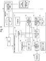
Figure 11 , anon-transitory storage medium 200 included in the computer terminal, the tablet terminal, or the smart phone stores the machining estimation program as an application program. ACPU 100 loads the machining estimation program in amain memory 300 and executes each command described in the machining estimation program.Figure 12A andFigure 12B show processing when theCPU 100 executes each command described in the machining estimation program.Figure 12A andFigure 12B show an operation of the machiningestimation apparatus 10 and processing of the machining estimation method executed by the machiningestimation apparatus 10. - In step S1 of
Figure 12A , theCPU 100 determines whether or not the machining estimation program is started. If the machining estimation program is not started (NO), theCPU 100 repeats the processing of step S1. If the machining estimation program is started (YES), in step S2, theCPU 100 causes thedisplay unit 17 to display theinput window 150 as shown inFigure 3 . - In step S3, the operator inputs each condition for estimation in the
input window 150. As shown inFigure 11 , theinput unit 15 is assumed to be a touch panel integrated with thedisplay unit 17. In step S4, theCPU 100 determines whether or not thecamera button 158 is pressed. If thecamera button 158 is not pressed (NO), theCPU 100 repeats the processing of step S4. If thecamera button 158 is pressed (YES), theCPU 100 starts thecamera 11 in step S5. - In Step S6, the
CPU 100 determines whether or not thedetermination button 111 and thecalculation button 113 are pressed. InFigure 12A , the determination as to whether or not thereturn button 112 is pressed and the processing when thereturn button 112 is pressed are omitted. If thedetermination button 111 and thecalculation button 113 are not pressed (NO), theCPU 100 repeats the processing of step S6. - In step S6, if the
determination button 111 and thecalculation button 113 are pressed (YES), theCPU 100 calculates the machining time in step S7, and then calculates the machining cost in step S8. In step S9, theCPU 100 displays the simulation result on thedisplay unit 17. - As shown in step S10 of
Figure 12B , theCPU 100 determines whether or not an operation to download the simulation result is performed. If the operation to download the simulation result is performed (YES), theCPU 100 downloads the simulation result into theHDD 60 in step S11 and moves the processing to step S12. If the operation to download the simulation result is not performed (NO), theCPU 100 moves the processing to step S12. - In step S12, the
CPU 100 determines whether or not the operation to print the machiningestimation simulation report 400 is performed. If the operation to print the machiningestimation simulation report 400 is performed (YES), theCPU 100 instructs theprinter 40 to print the machiningestimation simulation report 400 in step S13, and move the processing to step S14. If the operation to print the machiningestimation simulation report 400 is not performed (NO), theCPU 100 moves the processing to step S14. - In step S14, the
CPU 100 determines whether or not an operation of re-photography by there-photography button 165 is performed. If the operation of re-photography is performed (YES), in step S15 shown inFigure 12A , theCPU 100 restores the photographedimage 110 ofFigure 5 , and returns the processing to step S6. If the operation of re-photography is not performed (NO), theCPU 100 determines whether or not thereturn button 166 is pressed in step S16. If thereturn button 166 is pressed (YES), theCPU 100 returns the processing to step S2 shown inFigure 12A . - If the
return button 166 is not pressed in step S16 (NO), in step S17, theCPU 100 determined whether or not an operation to end the machining estimation program is performed. If the operation to end the machining estimation program is not performed (NO), theCPU 100 returns the processing to step S9 shown inFigure 12A . If the operation to end the machining estimation program is performed (YES), theCPU 100 ends the processing. - The present invention is not limited to the one or more embodiments described above, and various modifications can be made without departing from the scope of the present invention. In the one or more embodiments, the machining
cost calculation unit 14 is provided to estimate the machining cost, but it is not mandatory to estimate the machining cost, and only the machining time may be estimated. However, it is preferable to estimate both the machining time and the machining cost. - In configuring the machining estimation apparatus in the one or more embodiments, use of hardwear and software is optional. The machining estimation program may be transmitted to the computer terminal, the tablet terminal, or the smartphone via a network such as the Internet so as to be downloaded.
- The disclosure of the present application is related to the subject matter described in
Japanese Patent Application No. 2019-033758 filed on February 27, 2019
Claims (11)
- A machining estimation apparatus, comprising:a camera configured to photograph a part to be estimated and a dimension reference marker, the part to be estimated being produced by cutting a sheet metal in advance;an image processing unit configured to generate edge data by extracting an edge of the part photographed by the camera, and enlarges or reduces the edge data based on a size of the dimension reference marker photographed by the camera such that a size of the edge corresponds to an actual size of the part; anda machining time calculation unit configured to calculate a length of a cutting line for cutting out the part from the sheet metal based on the edge of the edge data corresponding to the actual size of the part, and calculate a machining time for producing the part by cutting the cutting line in accordance with a material and a thickness of the sheet metal.
- The machining estimation apparatus according to claim 1, wherein the machining time calculation unit calculates the machining time based on a total time of a time for making a pierced hole in the sheet metal, a time for cutting an approach from the pierced hole to the cutting line, and a time for cutting the cutting line.
- The machining estimation apparatus according to claim 2, wherein the machining time calculation unit multiplies the total time by a coefficient that is equal to or more than one so that a time, in which a movement time of a machining head that emits a laser beam to the metal sheet to cut the metal sheet is added to the total time, is the machining time.
- The machining estimation apparatus according to claim 3, further comprising a communication unit configured to read out a coefficient accumulated in an external server, wherein
the machining time calculation unit multiplies the total time by the coefficient that the communication unit reads out from the server. - The machining estimation apparatus according to any one of claims 1 to 4, further comprising a machining cost calculation unit configured to calculate a machining cost of the part based on the machining time calculated by the machining time calculation unit.
- A machining estimation method, comprising:photographing, by a camera, a part to be estimated and a dimension reference marker, the part to be estimated being produced by cutting a sheet metal in advance;generating, by an image processing unit, edge data by extracting an edge of the part photographed by the camera;enlarging or reducing, by the image processing unit, the edge data based on a size of the dimension reference marker photographed by the camera such that a size of the edge corresponds to an actual size of the part; andcalculating, by a machining time calculation unit, a length of a cutting line for cutting out the part from the sheet metal based on the edge of the edge data corresponding to the actual size of the part, and calculating, by the machining time calculation unit, a machining time for producing the part by cutting the cutting line in accordance with a material and a thickness of the sheet metal.
- A machining estimation program causing a computer to execute:a step of generating, based on photographed image data obtained by photographing a part to be estimated and a dimension reference marker by a camera, edge data by extracting an edge of the part to be estimated, the part to be estimated being produced by cutting a sheet metal in advance;a step of enlarging or reducing the edge data based on a size of the dimension reference marker in the photographed image data such that a size of the edge corresponds to an actual size of the part;a step of calculating a length of a cutting line for cutting out the part from the sheet metal based on the edge of the edge data corresponding to the actual size of the part; anda step of calculating a machining time for producing the part by cutting the cutting line in accordance with a material and a thickness of the sheet metal.
- The machining estimation program according to claim 7, further causing the computer to execute a step of calculating the machining time based on a total time of a time for making a pierced hole in the sheet metal, a time for cutting an approach from the pierced hole to the cutting line, and a time for cutting the cutting line.
- The machining estimation program according to claim 8, further causing the computer to execute a step of multiplying the total time by a coefficient that is equal to or more than one so that a time, in which a movement time of a machining head that emits a laser beam to the metal sheet to cut the metal sheet is added to the total time, is the machining time.
- The machining estimation program according to claim 9, further causing the computer to execute:a step of reading out a coefficient accumulated in an external server; anda step of multiplying the total time by the coefficient read out from the server.
- The machining estimation program according to any one of claims 7 to 10, further causing the computer to execute a step of calculating a machining cost of the part based on the calculated machining time.
Applications Claiming Priority (2)
| Application Number | Priority Date | Filing Date | Title |
|---|---|---|---|
| JP2019033758A JP6670961B1 (en) | 2019-02-27 | 2019-02-27 | Processing estimation device, processing estimation method, and processing estimation program |
| PCT/JP2020/003716 WO2020175013A1 (en) | 2019-02-27 | 2020-01-31 | Processing estimation device, processing estimation method, and processing estimation program |
Publications (3)
| Publication Number | Publication Date |
|---|---|
| EP3932607A1 true EP3932607A1 (en) | 2022-01-05 |
| EP3932607A4 EP3932607A4 (en) | 2022-04-06 |
| EP3932607B1 EP3932607B1 (en) | 2023-04-19 |
Family
ID=70000786
Family Applications (1)
| Application Number | Title | Priority Date | Filing Date |
|---|---|---|---|
| EP20762566.6A Active EP3932607B1 (en) | 2019-02-27 | 2020-01-31 | Processing estimation device, processing estimation method, and processing estimation program |
Country Status (5)
| Country | Link |
|---|---|
| US (1) | US11914352B2 (en) |
| EP (1) | EP3932607B1 (en) |
| JP (1) | JP6670961B1 (en) |
| CN (1) | CN113490570B (en) |
| WO (1) | WO2020175013A1 (en) |
Families Citing this family (1)
| Publication number | Priority date | Publication date | Assignee | Title |
|---|---|---|---|---|
| CN116944700B (en) * | 2023-08-31 | 2024-02-09 | 深圳市军志丰精密科技有限公司 | Detection and control methods and systems for laser cutting |
Family Cites Families (19)
| Publication number | Priority date | Publication date | Assignee | Title |
|---|---|---|---|---|
| DE8816754U1 (en) * | 1988-02-16 | 1990-07-05 | Dr. Johannes Heidenhain Gmbh, 8225 Traunreut | Post-form arrangement |
| JP2687736B2 (en) * | 1991-02-22 | 1997-12-08 | 日本電気株式会社 | Sheet metal product costing device |
| JPH06320344A (en) * | 1993-05-10 | 1994-11-22 | Fanuc Ltd | Electric discharge machining device |
| CN1217986A (en) | 1997-11-12 | 1999-06-02 | 渡辺正博 | Automatic three-dimension engraving device |
| JP2001101430A (en) * | 1999-10-01 | 2001-04-13 | Hitachi Plant Eng & Constr Co Ltd | CAD drawing creation support method and apparatus |
| JP3610302B2 (en) | 2000-12-28 | 2005-01-12 | 株式会社アマダ | Cost estimation method for sheet metal working |
| CN1392063A (en) | 2001-06-20 | 2003-01-22 | 株式会社日立工程服务 | Reproduction production device |
| CN1402173A (en) * | 2001-08-07 | 2003-03-12 | 株式会社理光 | Cost estimating method and system |
| KR20100086883A (en) * | 2009-01-23 | 2010-08-02 | 이용호 | Method of automatically calculate processing cost for sheet metal working which uses autocad |
| CN102441581A (en) | 2010-09-30 | 2012-05-09 | 邓玥 | Device and method for online detection of section size of profile steel based on machine vision |
| CN103218467A (en) | 2012-01-19 | 2013-07-24 | 昆山思拓机器有限公司 | Method for producing open file by utilizing finished product |
| JP2013246487A (en) * | 2012-05-23 | 2013-12-09 | Zero Four Co Ltd | Estimation device and estimation method |
| JP2015170008A (en) * | 2014-03-05 | 2015-09-28 | 三菱電機株式会社 | Standard processing time estimation supporting device and standard processing time estimation supporting method |
| CN104339658A (en) | 2014-11-15 | 2015-02-11 | 安徽省新方尊铸造科技有限公司 | Customized product manufacturing method combined with laser three-dimensional scanning and 3D (Three-dimensional) printing |
| CN104966138B (en) * | 2015-07-22 | 2019-05-10 | 成都四威高科技产业园有限公司 | Numerical control working hour predictor method |
| JP6309986B2 (en) * | 2016-02-18 | 2018-04-11 | ファナック株式会社 | Machining time prediction device for numerically controlled machine tools |
| CN107262933B (en) | 2017-06-22 | 2019-04-02 | 歌尔股份有限公司 | A kind of parts machining method and system |
| CN107180790B (en) * | 2017-06-29 | 2020-07-17 | 华进半导体封装先导技术研发中心有限公司 | Wafer cutting time calculation method and device |
| JP2019033758A (en) | 2018-10-31 | 2019-03-07 | 株式会社ナガセビューティケァ | Fermented lactic acid bacteria of cruciferous plants, food containing the fermented product, cosmetics and epithelial barrier enhancer, and method for producing the fermented product |
-
2019
- 2019-02-27 JP JP2019033758A patent/JP6670961B1/en active Active
-
2020
- 2020-01-31 CN CN202080017177.6A patent/CN113490570B/en active Active
- 2020-01-31 WO PCT/JP2020/003716 patent/WO2020175013A1/en not_active Ceased
- 2020-01-31 EP EP20762566.6A patent/EP3932607B1/en active Active
- 2020-01-31 US US17/432,967 patent/US11914352B2/en active Active
Also Published As
| Publication number | Publication date |
|---|---|
| WO2020175013A1 (en) | 2020-09-03 |
| CN113490570A (en) | 2021-10-08 |
| US20220155762A1 (en) | 2022-05-19 |
| JP6670961B1 (en) | 2020-03-25 |
| EP3932607A4 (en) | 2022-04-06 |
| JP2020140305A (en) | 2020-09-03 |
| CN113490570B (en) | 2024-03-19 |
| EP3932607B1 (en) | 2023-04-19 |
| US11914352B2 (en) | 2024-02-27 |
Similar Documents
| Publication | Publication Date | Title |
|---|---|---|
| US10261738B2 (en) | Plug-in software program, function extension method, and function extension device | |
| JP6333027B2 (en) | Printing system, printing control apparatus, printing apparatus, program, and storage medium | |
| CN104015505B (en) | Printing device, control method of printing device, and control device | |
| JP5834544B2 (en) | Program, print data generation apparatus, control method for print data generation apparatus, and printing system | |
| EP3932607B1 (en) | Processing estimation device, processing estimation method, and processing estimation program | |
| JP5803346B2 (en) | Display device, portable terminal, display device control method and program | |
| US20170006184A1 (en) | Determining image rescale factors | |
| CN116483291A (en) | Editing method, recording medium and information processing device | |
| US8014023B2 (en) | System and method for identifying attributes of a printed image | |
| US20070100490A1 (en) | Method and apparatus for providing custom-cut film covering to a consumer | |
| US20160311245A1 (en) | Method of Manufacturing Foil Stamped Artwork | |
| JP4525405B2 (en) | Print image display device, print image display method, and print image display program | |
| JP2002073288A (en) | Peripheral device control device, peripheral device control method, and computer-readable storage medium storing peripheral device control program | |
| JP6086880B2 (en) | 3D design apparatus, method and program | |
| JP2005208689A (en) | Electronic submission system, control method thereof, and control program | |
| JP2014085903A (en) | Printing system, printing data generation device, control method of printing data generation device, and program | |
| KR20200115726A (en) | The method to predict output time and material usage with files for 3d printing | |
| JP6083458B2 (en) | Display device, portable terminal, display device control method and program | |
| JP4821450B2 (en) | Information processing apparatus, information processing method, and information processing program | |
| US20150324674A1 (en) | Printing system, printing assistance apparatus and method | |
| US20220391546A1 (en) | Server apparatus, non-transitory computer readable recording medium, and discriminating method | |
| TW202613798A (en) | The editing methods, programs, and information processing devices executed by a computer. | |
| JP2021157256A (en) | Information processing device, storage medium storing display program, and display method | |
| JP2005228218A (en) | Construction workload estimation system | |
| JPH05225444A (en) | Goods unit price managing device classified by every customer |
Legal Events
| Date | Code | Title | Description |
|---|---|---|---|
| STAA | Information on the status of an ep patent application or granted ep patent |
Free format text: STATUS: THE INTERNATIONAL PUBLICATION HAS BEEN MADE |
|
| PUAI | Public reference made under article 153(3) epc to a published international application that has entered the european phase |
Free format text: ORIGINAL CODE: 0009012 |
|
| STAA | Information on the status of an ep patent application or granted ep patent |
Free format text: STATUS: REQUEST FOR EXAMINATION WAS MADE |
|
| 17P | Request for examination filed |
Effective date: 20210823 |
|
| AK | Designated contracting states |
Kind code of ref document: A1 Designated state(s): AL AT BE BG CH CY CZ DE DK EE ES FI FR GB GR HR HU IE IS IT LI LT LU LV MC MK MT NL NO PL PT RO RS SE SI SK SM TR |
|
| A4 | Supplementary search report drawn up and despatched |
Effective date: 20220307 |
|
| RIC1 | Information provided on ipc code assigned before grant |
Ipc: G05B 19/401 20060101ALI20220301BHEP Ipc: G05B 19/4069 20060101ALI20220301BHEP Ipc: G06Q 50/04 20120101ALI20220301BHEP Ipc: G06Q 30/06 20120101ALI20220301BHEP Ipc: B23K 26/382 20140101ALI20220301BHEP Ipc: B23K 26/38 20140101ALI20220301BHEP Ipc: B23K 26/03 20060101AFI20220301BHEP |
|
| DAV | Request for validation of the european patent (deleted) | ||
| DAX | Request for extension of the european patent (deleted) | ||
| GRAP | Despatch of communication of intention to grant a patent |
Free format text: ORIGINAL CODE: EPIDOSNIGR1 |
|
| STAA | Information on the status of an ep patent application or granted ep patent |
Free format text: STATUS: GRANT OF PATENT IS INTENDED |
|
| RIC1 | Information provided on ipc code assigned before grant |
Ipc: G05B 19/401 20060101ALI20221107BHEP Ipc: G05B 19/4069 20060101ALI20221107BHEP Ipc: G06Q 50/04 20120101ALI20221107BHEP Ipc: G06Q 30/06 20120101ALI20221107BHEP Ipc: B23K 26/382 20140101ALI20221107BHEP Ipc: B23K 26/38 20140101ALI20221107BHEP Ipc: B23K 26/03 20060101AFI20221107BHEP |
|
| INTG | Intention to grant announced |
Effective date: 20221130 |
|
| GRAS | Grant fee paid |
Free format text: ORIGINAL CODE: EPIDOSNIGR3 |
|
| GRAA | (expected) grant |
Free format text: ORIGINAL CODE: 0009210 |
|
| STAA | Information on the status of an ep patent application or granted ep patent |
Free format text: STATUS: THE PATENT HAS BEEN GRANTED |
|
| AK | Designated contracting states |
Kind code of ref document: B1 Designated state(s): AL AT BE BG CH CY CZ DE DK EE ES FI FR GB GR HR HU IE IS IT LI LT LU LV MC MK MT NL NO PL PT RO RS SE SI SK SM TR |
|
| REG | Reference to a national code |
Ref country code: GB Ref legal event code: FG4D |
|
| REG | Reference to a national code |
Ref country code: CH Ref legal event code: EP |
|
| REG | Reference to a national code |
Ref country code: DE Ref legal event code: R096 Ref document number: 602020009961 Country of ref document: DE |
|
| REG | Reference to a national code |
Ref country code: IE Ref legal event code: FG4D |
|
| REG | Reference to a national code |
Ref country code: AT Ref legal event code: REF Ref document number: 1560820 Country of ref document: AT Kind code of ref document: T Effective date: 20230515 |
|
| P01 | Opt-out of the competence of the unified patent court (upc) registered |
Effective date: 20230527 |
|
| REG | Reference to a national code |
Ref country code: LT Ref legal event code: MG9D |
|
| REG | Reference to a national code |
Ref country code: NL Ref legal event code: MP Effective date: 20230419 |
|
| REG | Reference to a national code |
Ref country code: AT Ref legal event code: MK05 Ref document number: 1560820 Country of ref document: AT Kind code of ref document: T Effective date: 20230419 |
|
| PG25 | Lapsed in a contracting state [announced via postgrant information from national office to epo] |
Ref country code: NL Free format text: LAPSE BECAUSE OF FAILURE TO SUBMIT A TRANSLATION OF THE DESCRIPTION OR TO PAY THE FEE WITHIN THE PRESCRIBED TIME-LIMIT Effective date: 20230419 |
|
| PG25 | Lapsed in a contracting state [announced via postgrant information from national office to epo] |
Ref country code: SE Free format text: LAPSE BECAUSE OF FAILURE TO SUBMIT A TRANSLATION OF THE DESCRIPTION OR TO PAY THE FEE WITHIN THE PRESCRIBED TIME-LIMIT Effective date: 20230419 Ref country code: PT Free format text: LAPSE BECAUSE OF FAILURE TO SUBMIT A TRANSLATION OF THE DESCRIPTION OR TO PAY THE FEE WITHIN THE PRESCRIBED TIME-LIMIT Effective date: 20230821 Ref country code: NO Free format text: LAPSE BECAUSE OF FAILURE TO SUBMIT A TRANSLATION OF THE DESCRIPTION OR TO PAY THE FEE WITHIN THE PRESCRIBED TIME-LIMIT Effective date: 20230719 Ref country code: ES Free format text: LAPSE BECAUSE OF FAILURE TO SUBMIT A TRANSLATION OF THE DESCRIPTION OR TO PAY THE FEE WITHIN THE PRESCRIBED TIME-LIMIT Effective date: 20230419 Ref country code: AT Free format text: LAPSE BECAUSE OF FAILURE TO SUBMIT A TRANSLATION OF THE DESCRIPTION OR TO PAY THE FEE WITHIN THE PRESCRIBED TIME-LIMIT Effective date: 20230419 |
|
| PG25 | Lapsed in a contracting state [announced via postgrant information from national office to epo] |
Ref country code: RS Free format text: LAPSE BECAUSE OF FAILURE TO SUBMIT A TRANSLATION OF THE DESCRIPTION OR TO PAY THE FEE WITHIN THE PRESCRIBED TIME-LIMIT Effective date: 20230419 Ref country code: PL Free format text: LAPSE BECAUSE OF FAILURE TO SUBMIT A TRANSLATION OF THE DESCRIPTION OR TO PAY THE FEE WITHIN THE PRESCRIBED TIME-LIMIT Effective date: 20230419 Ref country code: LV Free format text: LAPSE BECAUSE OF FAILURE TO SUBMIT A TRANSLATION OF THE DESCRIPTION OR TO PAY THE FEE WITHIN THE PRESCRIBED TIME-LIMIT Effective date: 20230419 Ref country code: LT Free format text: LAPSE BECAUSE OF FAILURE TO SUBMIT A TRANSLATION OF THE DESCRIPTION OR TO PAY THE FEE WITHIN THE PRESCRIBED TIME-LIMIT Effective date: 20230419 Ref country code: IS Free format text: LAPSE BECAUSE OF FAILURE TO SUBMIT A TRANSLATION OF THE DESCRIPTION OR TO PAY THE FEE WITHIN THE PRESCRIBED TIME-LIMIT Effective date: 20230819 Ref country code: HR Free format text: LAPSE BECAUSE OF FAILURE TO SUBMIT A TRANSLATION OF THE DESCRIPTION OR TO PAY THE FEE WITHIN THE PRESCRIBED TIME-LIMIT Effective date: 20230419 Ref country code: GR Free format text: LAPSE BECAUSE OF FAILURE TO SUBMIT A TRANSLATION OF THE DESCRIPTION OR TO PAY THE FEE WITHIN THE PRESCRIBED TIME-LIMIT Effective date: 20230720 Ref country code: AL Free format text: LAPSE BECAUSE OF FAILURE TO SUBMIT A TRANSLATION OF THE DESCRIPTION OR TO PAY THE FEE WITHIN THE PRESCRIBED TIME-LIMIT Effective date: 20230419 |
|
| PG25 | Lapsed in a contracting state [announced via postgrant information from national office to epo] |
Ref country code: FI Free format text: LAPSE BECAUSE OF FAILURE TO SUBMIT A TRANSLATION OF THE DESCRIPTION OR TO PAY THE FEE WITHIN THE PRESCRIBED TIME-LIMIT Effective date: 20230419 |
|
| PG25 | Lapsed in a contracting state [announced via postgrant information from national office to epo] |
Ref country code: SK Free format text: LAPSE BECAUSE OF FAILURE TO SUBMIT A TRANSLATION OF THE DESCRIPTION OR TO PAY THE FEE WITHIN THE PRESCRIBED TIME-LIMIT Effective date: 20230419 |
|
| REG | Reference to a national code |
Ref country code: DE Ref legal event code: R097 Ref document number: 602020009961 Country of ref document: DE |
|
| PG25 | Lapsed in a contracting state [announced via postgrant information from national office to epo] |
Ref country code: SM Free format text: LAPSE BECAUSE OF FAILURE TO SUBMIT A TRANSLATION OF THE DESCRIPTION OR TO PAY THE FEE WITHIN THE PRESCRIBED TIME-LIMIT Effective date: 20230419 Ref country code: SK Free format text: LAPSE BECAUSE OF FAILURE TO SUBMIT A TRANSLATION OF THE DESCRIPTION OR TO PAY THE FEE WITHIN THE PRESCRIBED TIME-LIMIT Effective date: 20230419 Ref country code: RO Free format text: LAPSE BECAUSE OF FAILURE TO SUBMIT A TRANSLATION OF THE DESCRIPTION OR TO PAY THE FEE WITHIN THE PRESCRIBED TIME-LIMIT Effective date: 20230419 Ref country code: EE Free format text: LAPSE BECAUSE OF FAILURE TO SUBMIT A TRANSLATION OF THE DESCRIPTION OR TO PAY THE FEE WITHIN THE PRESCRIBED TIME-LIMIT Effective date: 20230419 Ref country code: DK Free format text: LAPSE BECAUSE OF FAILURE TO SUBMIT A TRANSLATION OF THE DESCRIPTION OR TO PAY THE FEE WITHIN THE PRESCRIBED TIME-LIMIT Effective date: 20230419 Ref country code: CZ Free format text: LAPSE BECAUSE OF FAILURE TO SUBMIT A TRANSLATION OF THE DESCRIPTION OR TO PAY THE FEE WITHIN THE PRESCRIBED TIME-LIMIT Effective date: 20230419 |
|
| PLBE | No opposition filed within time limit |
Free format text: ORIGINAL CODE: 0009261 |
|
| STAA | Information on the status of an ep patent application or granted ep patent |
Free format text: STATUS: NO OPPOSITION FILED WITHIN TIME LIMIT |
|
| 26N | No opposition filed |
Effective date: 20240122 |
|
| PG25 | Lapsed in a contracting state [announced via postgrant information from national office to epo] |
Ref country code: SI Free format text: LAPSE BECAUSE OF FAILURE TO SUBMIT A TRANSLATION OF THE DESCRIPTION OR TO PAY THE FEE WITHIN THE PRESCRIBED TIME-LIMIT Effective date: 20230419 |
|
| PG25 | Lapsed in a contracting state [announced via postgrant information from national office to epo] |
Ref country code: SI Free format text: LAPSE BECAUSE OF FAILURE TO SUBMIT A TRANSLATION OF THE DESCRIPTION OR TO PAY THE FEE WITHIN THE PRESCRIBED TIME-LIMIT Effective date: 20230419 Ref country code: IT Free format text: LAPSE BECAUSE OF FAILURE TO SUBMIT A TRANSLATION OF THE DESCRIPTION OR TO PAY THE FEE WITHIN THE PRESCRIBED TIME-LIMIT Effective date: 20230419 |
|
| PG25 | Lapsed in a contracting state [announced via postgrant information from national office to epo] |
Ref country code: MC Free format text: LAPSE BECAUSE OF FAILURE TO SUBMIT A TRANSLATION OF THE DESCRIPTION OR TO PAY THE FEE WITHIN THE PRESCRIBED TIME-LIMIT Effective date: 20230419 |
|
| PG25 | Lapsed in a contracting state [announced via postgrant information from national office to epo] |
Ref country code: MC Free format text: LAPSE BECAUSE OF FAILURE TO SUBMIT A TRANSLATION OF THE DESCRIPTION OR TO PAY THE FEE WITHIN THE PRESCRIBED TIME-LIMIT Effective date: 20230419 |
|
| REG | Reference to a national code |
Ref country code: CH Ref legal event code: PL |
|
| PG25 | Lapsed in a contracting state [announced via postgrant information from national office to epo] |
Ref country code: LU Free format text: LAPSE BECAUSE OF NON-PAYMENT OF DUE FEES Effective date: 20240131 |
|
| GBPC | Gb: european patent ceased through non-payment of renewal fee |
Effective date: 20240131 |
|
| PG25 | Lapsed in a contracting state [announced via postgrant information from national office to epo] |
Ref country code: LU Free format text: LAPSE BECAUSE OF NON-PAYMENT OF DUE FEES Effective date: 20240131 |
|
| PG25 | Lapsed in a contracting state [announced via postgrant information from national office to epo] |
Ref country code: GB Free format text: LAPSE BECAUSE OF NON-PAYMENT OF DUE FEES Effective date: 20240131 |
|
| PG25 | Lapsed in a contracting state [announced via postgrant information from national office to epo] |
Ref country code: BE Free format text: LAPSE BECAUSE OF NON-PAYMENT OF DUE FEES Effective date: 20240131 |
|
| PG25 | Lapsed in a contracting state [announced via postgrant information from national office to epo] |
Ref country code: FR Free format text: LAPSE BECAUSE OF NON-PAYMENT OF DUE FEES Effective date: 20240131 |
|
| PG25 | Lapsed in a contracting state [announced via postgrant information from national office to epo] |
Ref country code: CH Free format text: LAPSE BECAUSE OF NON-PAYMENT OF DUE FEES Effective date: 20240131 |
|
| PG25 | Lapsed in a contracting state [announced via postgrant information from national office to epo] |
Ref country code: GB Free format text: LAPSE BECAUSE OF NON-PAYMENT OF DUE FEES Effective date: 20240131 Ref country code: FR Free format text: LAPSE BECAUSE OF NON-PAYMENT OF DUE FEES Effective date: 20240131 Ref country code: CH Free format text: LAPSE BECAUSE OF NON-PAYMENT OF DUE FEES Effective date: 20240131 Ref country code: BE Free format text: LAPSE BECAUSE OF NON-PAYMENT OF DUE FEES Effective date: 20240131 |
|
| REG | Reference to a national code |
Ref country code: BE Ref legal event code: MM Effective date: 20240131 |
|
| PG25 | Lapsed in a contracting state [announced via postgrant information from national office to epo] |
Ref country code: BG Free format text: LAPSE BECAUSE OF FAILURE TO SUBMIT A TRANSLATION OF THE DESCRIPTION OR TO PAY THE FEE WITHIN THE PRESCRIBED TIME-LIMIT Effective date: 20230419 |
|
| PG25 | Lapsed in a contracting state [announced via postgrant information from national office to epo] |
Ref country code: BG Free format text: LAPSE BECAUSE OF FAILURE TO SUBMIT A TRANSLATION OF THE DESCRIPTION OR TO PAY THE FEE WITHIN THE PRESCRIBED TIME-LIMIT Effective date: 20230419 |
|
| PG25 | Lapsed in a contracting state [announced via postgrant information from national office to epo] |
Ref country code: IE Free format text: LAPSE BECAUSE OF NON-PAYMENT OF DUE FEES Effective date: 20240131 |
|
| PG25 | Lapsed in a contracting state [announced via postgrant information from national office to epo] |
Ref country code: IE Free format text: LAPSE BECAUSE OF NON-PAYMENT OF DUE FEES Effective date: 20240131 |
|
| PG25 | Lapsed in a contracting state [announced via postgrant information from national office to epo] |
Ref country code: CY Free format text: LAPSE BECAUSE OF FAILURE TO SUBMIT A TRANSLATION OF THE DESCRIPTION OR TO PAY THE FEE WITHIN THE PRESCRIBED TIME-LIMIT; INVALID AB INITIO Effective date: 20200131 |
|
| PG25 | Lapsed in a contracting state [announced via postgrant information from national office to epo] |
Ref country code: HU Free format text: LAPSE BECAUSE OF FAILURE TO SUBMIT A TRANSLATION OF THE DESCRIPTION OR TO PAY THE FEE WITHIN THE PRESCRIBED TIME-LIMIT; INVALID AB INITIO Effective date: 20200131 |
|
| PG25 | Lapsed in a contracting state [announced via postgrant information from national office to epo] |
Ref country code: TR Free format text: LAPSE BECAUSE OF FAILURE TO SUBMIT A TRANSLATION OF THE DESCRIPTION OR TO PAY THE FEE WITHIN THE PRESCRIBED TIME-LIMIT Effective date: 20230419 |
|
| PGFP | Annual fee paid to national office [announced via postgrant information from national office to epo] |
Ref country code: DE Payment date: 20260121 Year of fee payment: 7 |