EP3932606A1 - Joining device for friction stirring point, joined article having joined friction stirring point, and shoulder member - Google Patents
Joining device for friction stirring point, joined article having joined friction stirring point, and shoulder member Download PDFInfo
- Publication number
- EP3932606A1 EP3932606A1 EP20766479.8A EP20766479A EP3932606A1 EP 3932606 A1 EP3932606 A1 EP 3932606A1 EP 20766479 A EP20766479 A EP 20766479A EP 3932606 A1 EP3932606 A1 EP 3932606A1
- Authority
- EP
- European Patent Office
- Prior art keywords
- shoulder
- friction stir
- spot welding
- stir spot
- workpiece
- Prior art date
- Legal status (The legal status is an assumption and is not a legal conclusion. Google has not performed a legal analysis and makes no representation as to the accuracy of the status listed.)
- Withdrawn
Links
Images












Classifications
-
- B—PERFORMING OPERATIONS; TRANSPORTING
- B23—MACHINE TOOLS; METAL-WORKING NOT OTHERWISE PROVIDED FOR
- B23K—SOLDERING OR UNSOLDERING; WELDING; CLADDING OR PLATING BY SOLDERING OR WELDING; CUTTING BY APPLYING HEAT LOCALLY, e.g. FLAME CUTTING; WORKING BY LASER BEAM
- B23K20/00—Non-electric welding by applying impact or other pressure, with or without the application of heat, e.g. cladding or plating
- B23K20/12—Non-electric welding by applying impact or other pressure, with or without the application of heat, e.g. cladding or plating the heat being generated by friction; Friction welding
- B23K20/122—Non-electric welding by applying impact or other pressure, with or without the application of heat, e.g. cladding or plating the heat being generated by friction; Friction welding using a non-consumable tool, e.g. friction stir welding
- B23K20/1245—Non-electric welding by applying impact or other pressure, with or without the application of heat, e.g. cladding or plating the heat being generated by friction; Friction welding using a non-consumable tool, e.g. friction stir welding characterised by the apparatus
- B23K20/125—Rotary tool drive mechanism
-
- B—PERFORMING OPERATIONS; TRANSPORTING
- B23—MACHINE TOOLS; METAL-WORKING NOT OTHERWISE PROVIDED FOR
- B23K—SOLDERING OR UNSOLDERING; WELDING; CLADDING OR PLATING BY SOLDERING OR WELDING; CUTTING BY APPLYING HEAT LOCALLY, e.g. FLAME CUTTING; WORKING BY LASER BEAM
- B23K20/00—Non-electric welding by applying impact or other pressure, with or without the application of heat, e.g. cladding or plating
- B23K20/12—Non-electric welding by applying impact or other pressure, with or without the application of heat, e.g. cladding or plating the heat being generated by friction; Friction welding
- B23K20/122—Non-electric welding by applying impact or other pressure, with or without the application of heat, e.g. cladding or plating the heat being generated by friction; Friction welding using a non-consumable tool, e.g. friction stir welding
- B23K20/1245—Non-electric welding by applying impact or other pressure, with or without the application of heat, e.g. cladding or plating the heat being generated by friction; Friction welding using a non-consumable tool, e.g. friction stir welding characterised by the apparatus
- B23K20/1255—Tools therefor, e.g. characterised by the shape of the probe
-
- B—PERFORMING OPERATIONS; TRANSPORTING
- B32—LAYERED PRODUCTS
- B32B—LAYERED PRODUCTS, i.e. PRODUCTS BUILT-UP OF STRATA OF FLAT OR NON-FLAT, e.g. CELLULAR OR HONEYCOMB, FORM
- B32B15/00—Layered products comprising a layer of metal
- B32B15/01—Layered products comprising a layer of metal all layers being exclusively metallic
-
- B—PERFORMING OPERATIONS; TRANSPORTING
- B32—LAYERED PRODUCTS
- B32B—LAYERED PRODUCTS, i.e. PRODUCTS BUILT-UP OF STRATA OF FLAT OR NON-FLAT, e.g. CELLULAR OR HONEYCOMB, FORM
- B32B7/00—Layered products characterised by the relation between layers; Layered products characterised by the relative orientation of features between layers, or by the relative values of a measurable parameter between layers, i.e. products comprising layers having different physical, chemical or physicochemical properties; Layered products characterised by the interconnection of layers
- B32B7/04—Interconnection of layers
- B32B7/05—Interconnection of layers the layers not being connected over the whole surface, e.g. discontinuous connection or patterned connection
-
- B—PERFORMING OPERATIONS; TRANSPORTING
- B23—MACHINE TOOLS; METAL-WORKING NOT OTHERWISE PROVIDED FOR
- B23K—SOLDERING OR UNSOLDERING; WELDING; CLADDING OR PLATING BY SOLDERING OR WELDING; CUTTING BY APPLYING HEAT LOCALLY, e.g. FLAME CUTTING; WORKING BY LASER BEAM
- B23K2103/00—Materials to be soldered, welded or cut
- B23K2103/02—Iron or ferrous alloys
- B23K2103/04—Steel or steel alloys
-
- B—PERFORMING OPERATIONS; TRANSPORTING
- B23—MACHINE TOOLS; METAL-WORKING NOT OTHERWISE PROVIDED FOR
- B23K—SOLDERING OR UNSOLDERING; WELDING; CLADDING OR PLATING BY SOLDERING OR WELDING; CUTTING BY APPLYING HEAT LOCALLY, e.g. FLAME CUTTING; WORKING BY LASER BEAM
- B23K2103/00—Materials to be soldered, welded or cut
- B23K2103/08—Non-ferrous metals or alloys
- B23K2103/10—Aluminium or alloys thereof
Definitions
- the present invention relates to a friction stir spot welding apparatus, a welded workpiece subjected to friction stir spot welding, and a shoulder.
- a substantially columnar pin and a substantially cylindrical shoulder including a hollow into which the pin is inserted are used to weld a welded workpiece, and a tool driver that operates (drives) the pin and the shoulder (rotary tool; welding tool) is controlled as below.
- the present invention was made to solve the above conventional problems, and a first object of the present invention is to provide a friction stir spot welding apparatus that can make a welding time shorter than welding times of conventional friction stir spot welding apparatuses. Moreover, a second object of the present invention is to provide a friction stir spot welding apparatus that can make welding strength higher than welding strength of welded workpieces welded by the conventional friction stir spot welding apparatuses and also provide a welded workpiece that has higher welding strength than the welded workpieces welded by the conventional friction stir spot welding apparatuses.
- a friction stir spot welding apparatus includes: a pin that is columnar; a shoulder that is cylindrical, the pin being within the shoulder; a rotary driver that rotates the pin and the shoulder about an axis that coincides with a center axis of the pin; and an advance-retreat driver that advances and retreats the pin and the shoulder along the axis.
- a first groove is formed at a tip end portion of an outer peripheral surface of the shoulder so as to extend in a direction along the center axis of the pin.
- a friction stir spot welding apparatus includes: a pin that is columnar; a shoulder that is cylindrical, the pin being within the shoulder; a rotary driver that rotates the pin and the shoulder about an axis that coincides with a center axis of the pin; and an advance-retreat driver that advances and retreats the pin and the shoulder along the axis.
- a second groove is formed on a tip end surface of the shoulder so as to extend in a radial direction of the shoulder.
- a friction stir spot welding apparatus is a friction stir spot welding apparatus that performs friction stir spot welding with respect to a welded workpiece including a first workpiece and a second workpiece.
- the friction stir spot welding apparatus includes: a pin; a shoulder that is hollow, the pin being within the shoulder; a rotary driver that rotates the pin and the shoulder about an axis extending in a longitudinal direction of the pin and a longitudinal direction of the shoulder; and an advance-retreat driver that advances and retreats the pin and the shoulder along the axis.
- the shoulder is configured such that when the shoulder advances while rotating in the welded workpiece, a material softened by plastic flow flows in an advancing direction of the shoulder or a retreating direction of the shoulder.
- the welding strength of the welded workpiece is made higher than the welding strength of the welded workpiece welded by using the conventional friction stir spot welding apparatus.
- a welded workpiece according to the present invention is a welded workpiece subjected to friction stir spot welding by the above friction stir spot welding apparatus.
- a welded workpiece according to the present invention is a welded workpiece subjected to friction stir spot welding by a friction stir spot welding apparatus.
- the welded workpiece includes: a first workpiece; a second workpiece; and a hook in the first workpiece or the second workpiece.
- the welding time is made shorter than those of the conventional friction stir spot welding apparatuses.
- the welding strength of the welded workpiece is made higher than the welding strength of the welded workpiece welded by using the conventional friction stir spot welding apparatus.
- the welded workpiece of the present invention the welded workpiece having higher welding strength than the welded workpiece welded by the conventional friction stir spot welding apparatus is obtained.
- a friction stir spot welding apparatus includes: a pin that is columnar; a shoulder that is cylindrical, the pin being within the shoulder; a rotary driver that rotates the pin and the shoulder about an axis that coincides with a center axis of the pin; and an advance-retreat driver that advances and retreats the pin and the shoulder along the axis.
- a first groove is formed at a tip end portion of an outer peripheral surface of the shoulder so as to extend in a direction along the center axis of the pin.
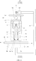
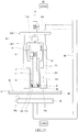
- FIG. 1 is a schematic diagram showing a schematic configuration of the friction stir spot welding apparatus according to Embodiment 1.
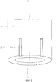
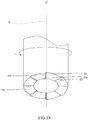
- FIG. 2 is a perspective view schematically showing a tip end portion of a shoulder of the friction stir spot welding apparatus shown in FIG. 1 .
- An upper-lower direction in FIG. 1 is shown as an upper-lower direction of the friction stir spot welding apparatus.
- a friction stir spot welding apparatus 50 includes a pin 11, a shoulder 12, a tool fixture 52, an advance-retreat driver 53, a clamp structure 13, a backing support 55, a backing structure 56, and a rotary driver 57.
- the pin 11, the shoulder 12, the tool fixture 52, the advance-retreat driver 53, the clamp structure 13, and the rotary driver 57 are disposed at an upper end portion of the backing support 55 constituted by a C-shaped gun (C-shaped frame). Moreover, the backing structure 56 is disposed at a lower end portion of the backing support 55.
- the pin 11, the shoulder 12, the clamp structure 13, and the backing structure 56 are attached to the backing support 55 at such positions that the pin 11, the shoulder 12, and the clamp structure 13 are opposed to the backing structure 56.
- a welded workpiece 60 is arranged between the pin 11 and the backing structure 56, between the shoulder 12 and the backing structure 56, and between the clamp structure 13 and the backing structure 56.
- the pin 11, the shoulder 12, and the clamp structure 13 are fixed to the tool fixture 52 constituted by a rotary tool fixture 521 and a clamp fixture 522. Specifically, the pin 11 and the shoulder 12 are fixed to the rotary tool fixture 521, and the clamp structure 13 is fixed to the clamp fixture 522 through a clamp driver 41.
- the rotary tool fixture 521 is supported by the clamp fixture 522 through the rotary driver 57.
- the clamp driver 41 is constituted by springs.
- the pin 11, the shoulder 12, and the clamp structure 13 are driven by the advance-retreat driver 53 constituted by a pin driver 531 and a shoulder driver 532, to advance and retreat in the upper-lower direction.
- the pin 11 is formed in a columnar shape. Although not shown in FIG. 1 in detail, the pin 11 is supported by the rotary tool fixture 521. The pin 11 may be supported by the rotary tool fixture 521 through a linear motion bearing (not shown).
- the pin 11 is rotated by the rotary driver 57 about an axis Xr (rotation axis) that coincides with a center axis of the pin 11. Furthermore, the pin 11 can advance and retreat by the pin driver 531 in a direction indicated by an arrow PI, i.e., in a direction along the axis Xr (in the upper-lower direction in FIG. 1 ).
- the pin driver 531 may apply pressure to the pin 11.
- a mechanism that utilizes gas pressure, hydraulic pressure, a servomotor, or the like may be suitably used.
- the shoulder 12 is formed in a cylindrical shape including a hollow and is supported by the rotary tool fixture 521.
- the pin 11 is inserted into the hollow of the shoulder 12.
- the shoulder 12 is arranged so as to surround an outer peripheral surface of the pin 11.
- the shoulder 12 is rotated by the rotary driver 57 about the same axis Xr as the pin 11. Furthermore, the shoulder can advance and retreat by the shoulder driver 532 in a direction indicated by an arrow P2, i.e., in the direction along the axis Xr.
- the shoulder driver 532 may apply pressure to the shoulder 12.
- a mechanism that utilizes gas pressure, hydraulic pressure, a servomotor, or the like may be suitably used.
- first grooves 21 are formed on an outer peripheral surface of a tip end portion (lower end portion) of the shoulder 12 so as to extend from a tip end surface 12a (tip end of the shoulder 12) (see FIGS. 1 and 2 ).
- the first grooves 21 are formed so as to extend in the direction along the axis Xr.
- the first grooves 21 are not limited to this and may be formed so as to extend in an oblique direction to the axis Xr.
- the first grooves 21 are provided at four positions.
- the first groove 21 may be provided at one position, or the first grooves 21 may be provided at plural positions (for example, two, six, or eight positions).
- the tip ends of the first grooves 21 coincide with the tip end of the shoulder 12.
- the present embodiment is not limited to this.
- the tip ends of the first grooves 21 may be located at a base end side (upper side) of the tip end of the shoulder 12.
- a length of each first groove 21 in a width direction may be 0.3 mm or more or 0.5 mm or more in order to improve welding strength of a welded portion of the welded workpiece 60.
- the length of each first groove 21 in the width direction may be 1.5 mm or less or 1.3 mm or less in order to reduce a welding time of the welded portion of the welded workpiece 60.
- a depth of the first groove 21 (length in a radial direction of the shoulder 12) may be 0.1 mm or more or 0.2 mm or more in order to improve the welding strength of the welded portion of the welded workpiece 60. Moreover, the depth of the first groove 21 may be 0.3 mm or less or 0.5 mm or less in order to reduce the welding time of the welded portion of the welded workpiece 60.
- a length of each first groove 21 in the direction along the axis Xr may be 2.0 mm or less or 1.8 mm or less in order to improve the welding strength of the welded portion of the welded workpiece 60.
- the length of each first groove 21 in the direction along the axis Xr may be 0.7 mm or more or 1.2 mm or more in order to reduce the welding time of the welded portion of the welded workpiece 60.
- the pin 11 and the shoulder 12 are supported by the rotary tool fixture 521 and are integrally rotated by the rotary driver 57 about the axis Xr. Moreover, the pin 11 can advance and retreat by the pin driver 531 in the direction along the axis Xr, and the shoulder 12 can advance and retreat by the shoulder driver 532 in the direction along the axis Xr.
- the pin 11 can independently advance and retreat, and in addition, can advance and retreat in accordance with the advancing and retreating of the shoulder 12.
- the pin 11 and the shoulder 12 may individually advance and retreat.
- the clamp structure 13 is formed in a cylindrical shape including a hollow.
- the clamp structure 13 is disposed such that a center axis of the clamp structure 13 coincides with the axis Xr.
- the shoulder 12 is inserted into the hollow of the clamp structure 13.
- the cylindrical shoulder 12 is arranged so as to surround the outer peripheral surface of the pin 11, and the cylindrical clamp structure 13 is arranged so as to surround an outer peripheral surface of the shoulder 12.
- the clamp structure 13, the shoulder 12, and the pin 11 constitute a coaxial nested structure.
- the clamp structure 13 presses one surface (front surface) of the welded workpiece 60.
- the clamp structure 13 is supported by the clamp fixture 522 through the clamp driver 41.
- the clamp driver 41 biases the clamp structure 13 toward the backing structure 56.
- the clamp structure 13 (and the clamp driver 41 and the clamp fixture 522) can advance and retreat by the shoulder driver 532 in a direction indicated by an arrow P3 (which is the same as the direction indicated by the arrow P1 and the direction indicated by the arrow P2).
- the clamp driver 41 is constituted by springs.
- the clamp driver 41 may apply biasing force or pressure to the clamp structure 13.
- a mechanism that utilizes gas pressure, hydraulic pressure, a servomotor, or the like may be suitably used.
- the pin 11, the shoulder 12, and the clamp structure 13 respectively include a tip end surface 11a, the tip end surface 12a, and a tip end surface 13a. Moreover, the pin 11, the shoulder 12, and the clamp structure 13 advance and retreat by the advance-retreat driver 53 to bring the tip end surface 11a, the tip end surface 12a, and the tip end surface 13a into contact with the front surface of the welded workpiece 60 (the welded portion of the welded workpiece 60) and press the welded workpiece 60.
- the backing structure 56 supports the welded workpiece 60 having a flat plate shape such that a flat surface (supporting surface 56a) of the backing structure 56 contacts a back surface of the welded workpiece 60.
- the configuration of the backing structure 56 is not especially limited as long as the backing structure 56 can appropriately support the welded workpiece 60 such that the friction stir spot welding is performed.
- the backing structures 56 of various shapes may be additionally prepared, and the backing structure 56 may be detachable from the backing support 55 and replaceable in accordance with the types of the welded workpieces 60.
- Embodiment 1 Specific configurations of the pin 11, the shoulder 12, the tool fixture 52, the advance-retreat driver 53, the clamp structure 13, the backing support 55, and the rotary driver 57 in Embodiment 1 are not limited to the above-described configurations, and configurations widely known in the field of the friction stir welding may be suitably used.
- the tool fixture 52 may be supported by the backing support 55 through a linear motion bearing (not shown).
- each of the pin driver 531 and the shoulder driver 532 may be constituted by a motor, a gear mechanism, and the like known in the field of the friction stir welding.
- the backing support 55 is constituted by the C-shaped gun but is not limited to this.
- the backing support 55 may have any configuration as long as: the backing support 55 can support the pin 11, the shoulder 12, and the clamp structure 13 such that the pin 11, the shoulder 12, and the clamp structure 13 can advance and retreat; and the backing support 55 can support the backing structure 56 at a position opposed to the pin 11, the shoulder 12, and the clamp structure 13.
- the friction stir spot welding apparatus 50 according to Embodiment 1 is disposed at a friction stir spot welding robot system (not shown).
- the backing support 55 is attached to a tip end of an arm of the robot system. Therefore, the backing support 55 can be regarded as being included in the friction stir spot welding robot system.
- a specific configuration of the friction stir spot welding robot system including the backing support 55 and the arm is not especially limited, and apparatuses, such as an articulated robot, known in the field of the friction stir welding can be suitably used.
- the present embodiment is not limited to a case where the friction stir spot welding apparatus 50 (including the backing support 55) is applied to the friction stir spot welding robot system.
- the friction stir spot welding apparatus 50 (including the backing support 55) is suitably applicable to known processing apparatuses, such as NC machining apparatuses, large C-shaped frames, and automatic riveters.
- the friction stir spot welding apparatus 50 may be configured such that two or more robots make the backing structure 56 and portions of the friction stir spot welding apparatus 50 other then the backing structure 56 face each other. Furthermore, as long as the friction stir spot welding apparatus 50 can stably perform the friction stir spot welding with respect to the welded workpiece 60, the welded workpiece 60 may be of a handy type, or a robot may be used as a positioner for the welded workpiece 60.
- FIG. 3 is a block diagram schematically showing the control configuration of the friction stir spot welding apparatus shown in FIG. 1 .
- the friction stir spot welding apparatus 50 includes a controller 51, a storage 31, an inputter 32, and a position detector 33.
- the controller 51 controls respective structures (respective devices) constituting the friction stir spot welding apparatus 50. Specifically, the controller 51 reads and executes software, such as a basic program, stored in the storage to control the pin driver 531 and shoulder driver 532 of the advance-retreat driver 53 and the rotary driver 57.
- software such as a basic program
- the controller 51 may be constituted by a single controller 51 which performs centralized control or may be constituted by controllers 51 which cooperate to perform distributed control. Moreover, the controller 51 may be constituted by a microcomputer or may be constituted by an MPU, a PLC (Programmable Logic Controller), a logic circuit, or the like.
- a microcomputer or may be constituted by an MPU, a PLC (Programmable Logic Controller), a logic circuit, or the like.
- the storage 31 stores a basic program and various data such that the basic program and various data are readable.
- the storage 31 is constituted by a known memory, a storage apparatus such as a hard disk, or the like.
- the storage 31 does not have to be a single storage and may be constituted as storage apparatuses (for example, a random access memory and a hard disc drive).
- the controller 51 and the like are constituted by a microcomputer, at least part of the storage 31 may be constituted as an internal memory of the microcomputer or may be constituted as an independent memory.
- the storage 31 stores data, and the data may be read by a device other than the controller 51, and the controller 51 and the like may write data in the storage 31.
- the inputter 32 inputs, to the controller 51, various parameters regarding the control of the friction stir spot welding, other data, and the like.
- the inputter 32 is constituted by a known input device, such as a keyboard, a touch panel, or a button switch group.
- a known input device such as a keyboard, a touch panel, or a button switch group.
- at least data of welding conditions of the welded workpiece 60 can be input by the inputter 32.
- the position detector 33 detects positional information of the tip end portion (tip end surface 12a) of the shoulder 12 and outputs the detected positional information to the controller 51.
- a LVDT, an encoder, or the like may be used as the position detector 33.
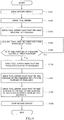
- FIG. 4 is a flow chart showing one example of the operation of the friction stir spot welding apparatus according to Embodiment 1.
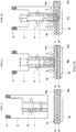
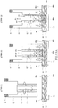
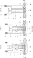
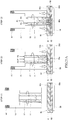
- FIGS. 5A and 5B is a process diagram schematically showing one example of steps of the friction stir spot welding performed by the friction stir spot welding apparatus shown in FIG. 1 .
- FIGS. 5A and 5B shows an example in which: a plate-shaped first workpiece 61 and a plate-shaped second workpiece 62 are used as the welded workpiece 60; and these workpieces 61 and 62 are laminated on each other and coupled to each other by spot welding.
- the first workpiece 61 and the second workpiece 62 may be made of metal (for example, aluminum or steel).
- the welded workpiece 60 is constituted by the plate-shaped first workpiece 61 and the plate-shaped second workpiece 62.
- the present embodiment is not limited to this, and the welded workpiece 60 (the first workpiece 61 and the second workpiece 62) may have any shape, and for example, may have a rectangular solid shape or a circular-arc shape.
- FIGS. 5A and 5B part of the double-acting friction welding apparatus is not shown.
- Arrows r indicate the rotational directions of the pin 11 and the shoulder 12
- block arrows F indicate directions of forces applied to the first workpiece 61 and the second workpiece 62.
- a worker places the welded workpiece 60 on the supporting surface 56a of the backing structure 56.
- the worker manipulates the inputter 32 to input execution of welding of the welded workpiece 60 to the controller 51.
- a robot may place the welded workpiece 60 on the supporting surface 56a of the backing structure 56.
- the controller 51 drives the rotary driver 57 to rotate the pin 11 and the shoulder 12 at a preset and predetermined first rotational frequency (for example, 200 to 3,000 rpm) (Step S101; see Step (1) in FIG. 5A ).
- a preset and predetermined first rotational frequency for example, 200 to 3,000 rpm
- Step S102 while driving the advance-retreat driver 53 (shoulder driver 532) to rotate the pin 11 and the shoulder 12, the controller 51 makes the pin 11, the shoulder 12, and the clamp structure 13 approach the welded workpiece 60 and brings the tip end surface 11a of the pin 11, the tip end surface 12a of the shoulder 12, and the tip end surface 13a of the clamp structure 13 (not shown in FIGS. 5A and 5B ) into contact with the front surface 60c of the welded workpiece 60 (Step S102; see Step (2) in FIG. 5A ).
- the controller 51 controls the advance-retreat driver 53 (shoulder driver 532) such that the pin 11, the shoulder 12, and the clamp structure 13 press the welded workpiece 60 by a preset and predetermined first pressing force (for example, a predetermined value within a range of 3 kN to 10 kN) as a whole.
- a preset and predetermined first pressing force for example, a predetermined value within a range of 3 kN to 10 kN
- first workpiece 61 and the second workpiece 62 are sandwiched by the clamp structure 13 and the backing structure 56, and the clamp structure 13 is biased toward the front surface 60c of the welded workpiece 60 by the contraction of the clamp driver 41 to generate clamping force.
- the front surface 60c of the welded workpiece 60 is subjected to "preheating." With this, a constituent material at a contact region of the first workpiece 61 is softened by heat generated by friction, and thus, a plastically flowing portion 60a is generated in the vicinity of the front surface 60c of the welded workpiece 60.
- the controller 51 drives the advance-retreat driver 53 such that the tip end surface 11a of the pin 11 sinks relative to the tip end surface 12a of the shoulder 12 (Step S103).
- the controller 51 may drive the advance-retreat driver 53 (pin driver 531) such that the pin 11 separates from the welded workpiece 60.
- the controller 51 may drive the advance-retreat driver 53 (shoulder driver 532) such that the shoulder 12 is pressed in the welded workpiece 60.
- Step S104 acquires the positional information of the tip end portion of the shoulder 12 from the position detector 33 (Step S104). Then, the controller 51 determines whether or not the positional information of the tip end portion of the shoulder 12 acquired in Step S104 has reached a preset and predetermined first position (Step S105).
- the first position may be set in advance by experiments or the like.
- a surface of the first workpiece 61 (the front surface 60c of the welded workpiece 60) is regarded as 0%, and a surface of the second workpiece 62 which surface contacts the supporting surface 56a is regarded as 100%
- the first position is set arbitrarily within a range of more than 0% and less than 100%.
- the first position is preferably located close to the surface of the second workpiece 62 which surface contacts the supporting surface 56a.
- the first position may be 25% or more, 50% or more, 75% or more, 80% or more, 90% or more, or 95% or more.
- a softened part of the welded workpiece 60 extends from the first workpiece 61 at the upper side to the second workpiece 62 at the lower side, and the volume of the plastically flowing portion 60a increases. Moreover, a softened material of the plastically flowing portion 60a is pushed away by the shoulder 12 to flow from a position right under the shoulder 12 to a position right under the pin 11. Therefore, the pin 11 retreats and moves upward relative to the shoulder 12 (see Step (3) in FIG. 5A ).
- Step S104 determines that the positional information of the tip end portion of the shoulder 12 acquired in Step S104 has not yet reached the first position (No in Step S105)
- the controller 51 returns to Step S104.
- the controller 51 repeatedly performs Steps S104 and S105 until the controller 51 determines that the positional information of the tip end portion of the shoulder 12 acquired in Step S104 has reached the first position.
- Step S106 when the controller 51 determines that the positional information of the tip end portion of the shoulder 12 acquired in Step S104 has reached the first position (Yes in Step S105), the controller 51 performs Step S106.
- Step S106 the controller 51 drives the advance-retreat driver 53 (pin driver 531) such that the pin 11 advances toward the welded workpiece 60, or the controller 51 drives the advance-retreat driver 53 (shoulder driver 532) such that the shoulder 12 separates from the welded workpiece 60.
- the pin 11 gradually advances toward the first workpiece 61, and the shoulder 12 retreats from the first workpiece 61 (see Step (4) in FIG. 5B ).
- the softened part of the plastically flowing portion 60a flows from the position right under the pin 11 to the position right under the shoulder 12 (to a recess generated by press-in of the shoulder 12).
- the controller 51 may control the advance-retreat driver 53 such that the tip end surface 11a of the pin 11 is located at the first position. Moreover, the controller 51 may control the advance-retreat driver 53 such that the tip end surface 11a of the pin 11 reaches an inside of the second workpiece 62 or may control the advance-retreat driver 53 such that the tip end surface 11a of the pin 11 is located inside the first workpiece 61.
- controller 51 control the advance-retreat driver 53 in Step S103 and/or Step S106 so as to reduce an absolute value of a tool average position Tx defined by Formula (I) below.
- Ap ⁇ Pp + As ⁇ Ps Tx
- the controller 51 controls the advance-retreat driver 53 such that almost no level difference is generated between the tip end surface 11a of the pin 11 and the tip end surface 12a of the shoulder 12 (the tip end surface 11a of the pin 11 and the tip end surface 12a of the shoulder 12 are flush with each other) (Step S107; see Step (5) in FIG. 5B ).
- the front surface 60c of the welded workpiece 60 is shaped, and a substantially flat surface where recesses are not practically generated is obtained.
- the controller 51 drives the advance-retreat driver 53 such that the pin 11, the shoulder 12, and the clamp structure 13 separate from the welded workpiece 60 (Step S108). Then, the controller 51 controls the rotary driver 57 to stop the rotation of the pin 11 and the shoulder 12 (Step S109; see Step (6) in FIG. 5B ) and terminates the friction stir spot welding (step of welding the welded workpiece 60).
- the first grooves 21 are formed on the outer peripheral surface of the tip end portion of the shoulder 12 so as to extend from the tip end surface 12a of the shoulder 12. With this, stirring of the first workpiece 61 and/or the second workpiece 62 is promoted, and this can reduce the welding time.
- the welding strength is made higher than the welding strength of the welded workpiece welded by using the conventional shoulder 12 not including the first grooves 21.
- the friction stir spot welding apparatus according to Modified Example 1 of Embodiment 1 is configured such that in the friction stir spot welding apparatus according to Embodiment 1, second grooves are formed on the tip end surface of the shoulder so as to extend in the radial direction of the shoulder.
- FIG. 6 is a perspective view schematically showing a major component (the tip end portion of the shoulder) of the friction stir spot welding apparatus according to Modified Example 1 of Embodiment 1.
- the friction stir spot welding apparatus according to Modified Example 1 of Embodiment 1 is the same in basic configuration as the friction stir spot welding apparatus 50 according to Embodiment 1 but is different from the friction stir spot welding apparatus 50 according to Embodiment 1 in that in addition to the first grooves 21, second grooves 22 are provided on the tip end surface 12a of the shoulder 12.
- each of the second grooves 22 is formed so as to extend in the radial direction passing through a center (center axis) of the shoulder 12.
- the present embodiment is not limited to this.
- Each of the second grooves 22 may be formed so as to extend in an oblique direction to the radial direction.
- the second grooves 22 are provided at four positions.
- the second groove 22 may be provided at one position, or the second grooves 22 may be provided at plural positions (for example, two, six, or eight positions).
- the second grooves 22 are provided so as to communicate with the first grooves 21.
- the present embodiment is not limited to this.
- the second grooves 22 may be provided so as not to communicate with the first grooves 21.
- a friction stir spot welding apparatus includes: a pin that is columnar; a shoulder that is cylindrical, the pin being within the shoulder; a rotary driver that rotates the pin and the shoulder about an axis that coincides with a center axis of the pin; and an advance-retreat driver that advances and retreats the pin and the shoulder along the axis.
- a second groove is formed on a tip end surface of the shoulder so as to extend in a radial direction of the shoulder.
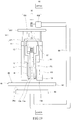
- FIG. 7 is a schematic diagram showing a schematic configuration of the friction stir spot welding apparatus according to Embodiment 2.
- FIG. 8 is a perspective view schematically showing the tip end portion of the shoulder of the friction stir spot welding apparatus shown in FIG. 7 .
- An upper-lower direction in FIG. 7 is shown as an upper-lower direction of the friction stir spot welding apparatus.
- the friction stir spot welding apparatus 50 according to Embodiment 2 is the same in basic configuration as the friction stir spot welding apparatus 50 according to Embodiment 1 but is different from the friction stir spot welding apparatus 50 according to Embodiment 1 in that instead of the first grooves 21, the second grooves 22 are provided on the tip end surface 12a of the shoulder 12.
- each of the second grooves 22 is formed so as to extend in the radial direction passing through the center (center axis) of the shoulder 12.
- the present embodiment is not limited to this.
- Each of the second grooves 22 may be formed so as to extend in an oblique direction to the radial direction.
- the second grooves 22 are provided at four positions.
- the second groove 22 may be provided at one position, or the second grooves 22 may be provided at plural positions (for example, two, six, or eight positions).
- the friction stir spot welding apparatus 50 according to Embodiment 2 configured as above archives the same operational advantages as the friction stir spot welding apparatus 50 according to Embodiment 1.
- the second grooves 22 of the friction stir spot welding apparatus 50 according to Embodiment 2 may be provided at the shoulder 12 of the friction stir spot welding apparatus 50 according to Embodiment 1.
- the first grooves 21 may be provided on the outer peripheral surface of the tip end portion of the shoulder 12, and the second grooves 22 may be provided on the tip end surface 12a of the shoulder 12.
- the first grooves 21 were provided on the outer peripheral surface of the tip end portion of the shoulder 12. Specifically, the first grooves 21 were provided at four positions on the outer peripheral surface of the tip end portion of the shoulder 12, and the length of each first groove 21 in the width direction (circumferential direction of the shoulder 12) was 1.5 mm. Moreover, the depth (length in the radial direction of the shoulder 12) of each first groove 21 was 0.3 mm, and the length of each first groove 21 in the direction along the axis Xr was 2.0 mm.
- the first grooves 21 were provided on the outer peripheral surface of the tip end portion of the shoulder 12. Specifically, the first grooves 21 were provided at four positions on the outer peripheral surface of the tip end portion of the shoulder 12, and the length of each first groove 21 in the width direction was 0.5 mm. Moreover, the depth of each first groove 21 was 0.2 mm, and the length of each first groove 21 in the direction along the axis Xr was 1.8 mm.
- the first grooves 21 were provided on the outer peripheral surface of the tip end portion of the shoulder 12. Specifically, the first grooves 21 were provided at eight positions on the outer peripheral surface of the tip end portion of the shoulder 12, and the length of each first groove 21 in the width direction was 0.5 mm. Moreover, the depth of each first groove 21 was 0.2 mm, and the length of each first groove 21 in the direction along the axis Xr was 1.8 mm.
- second grooves 221 were provided on the tip end surface 12a of the shoulder 12.
- the second grooves 22 were provided at four positions on the tip end surface 12a of the shoulder 12.
- the length of each second groove 22 in the width direction (circumferential direction of the shoulder 12) was 1.73 mm
- the depth (length in the direction along the axis Xr) of each second groove 22 was 0.5 mm.
- the shoulder 12 was the same in configuration as the conventional shoulder 12 and did not include the first grooves 21 and the second grooves 22.
- the first and second workpieces 61 and 62 were subjected to the friction stir spot welding by each of the friction stir spot welding apparatuses 50 according to Comparative Example and Test Examples 1 to 4, and the welding time was measured.
- the welding time was measured as a period of time from when the tip end surface 11a of the pin 11 and the tip end surface 12a of the shoulder 12 were brought into contact with the front surface 60c of the welded workpiece 60 until when the tip end surface 11a of the pin 11 and the tip end surface 12a of the shoulder 12 were separated from the front surface 60c of the welded workpiece 60.
- FIG. 9 is a graph showing the welding times as the results of the friction stir spot welding performed by using the friction stir spot welding apparatuses of Comparative Example and Test Examples 1 to 4 and also showing the results of the cross tension test.
- each of the welding time and the result of the cross tension test when the friction stir spot welding apparatus 50 according to Comparative Example was used is shown as 100%, and based on this, the welding times and the results of the cross tension test when the friction stir spot welding apparatuses 50 of Test Examples 1 to 4 were used to perform the friction stir spot welding are shown.
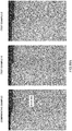
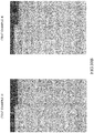
- FIGS. 10A and 10B show pictures of sections of the welded workpieces subjected to the friction stir spot welding by using the friction stir spot welding apparatuses of Comparative Example and Test Examples 1 to 4.
- a friction stir spot welding apparatus is a friction stir spot welding apparatus that performs friction stir spot welding with respect to a welded workpiece including a first workpiece and a second workpiece.
- the friction stir spot welding apparatus includes: a pin; a shoulder that is hollow, the pin being within the shoulder; a rotary driver that rotates the pin and the shoulder about an axis extending in a longitudinal direction of the pin and a longitudinal direction of the shoulder; and an advance-retreat driver that advances and retreats the pin and the shoulder along the axis.
- the shoulder is configured such that when the shoulder advances while rotating in the welded workpiece, a material softened by plastic flow flows in an advancing direction of the shoulder.
- the advancing direction of the shoulder denotes a direction in which the shoulder advances toward the welded workpiece.
- a retreating direction of the shoulder is a direction in which the shoulder separates from the welded workpiece.
- the shoulder may be configured such that a hook of the welded workpiece is formed so as to be directed in the advancing direction of the shoulder.
- tensile strength of the first workpiece may be higher than that of the second workpiece, and the shoulder may be configured such that the hook of the welded workpiece is formed at the first workpiece which has not yet been subjected to the welding.
- the tensile strength denotes strength measured based on JIS Z2241.
- a first groove may be formed on an outer peripheral surface of a tip end portion of the shoulder, and the first groove may be formed such that a front end thereof in a rotational direction of the shoulder is located closer to a base end of the shoulder than a rear end thereof in the rotational direction of the shoulder.
- a tip end portion of the first groove may be formed at a position away from a tip end of the shoulder toward a base end portion of the shoulder.
- the welded workpiece according to Embodiment 3 may be a welded workpiece subjected to the friction stir spot welding by any of the friction stir spot welding apparatuses according to Embodiment 3.
- the tensile strength of the first workpiece may be higher than that of the second workpiece, and the hook may be formed at the first workpiece which has not yet been subjected to the welding.
- the welded workpiece according to Embodiment 3 is a welded workpiece subjected to the friction stir spot welding by the friction stir spot welding apparatus and includes the first workpiece and the second workpiece, and the hook is formed in the first workpiece or the second workpiece.
- the shoulder according to Embodiment 3 includes a recess and/or a projection on the outer peripheral surface thereof, each of the recess and the projection including such an inclined portion that a part thereof in the rotational direction of the shoulder is located closer to the base end of the shoulder than another part thereof in the rotational direction of the shoulder.
- FIG. 11 is a schematic diagram showing a schematic configuration of the friction stir spot welding apparatus according to Embodiment 3.
- FIG. 12 is a perspective view schematically showing the tip end portion of the shoulder of the friction stir spot welding apparatus shown in FIG. 11 .
- An upper-lower direction in FIG. 11 is shown as an upper-lower direction of the friction stir spot welding apparatus.
- the friction stir spot welding apparatus 50 according to Embodiment 3 is the same in basic configuration as the friction stir spot welding apparatus 50 according to Embodiment 1 but is different from the friction stir spot welding apparatus 50 according to Embodiment 1 regarding the shape of the shoulder 12. Since the control configuration of the friction stir spot welding apparatus 50 according to Embodiment 3 is the same as that of the friction stir spot welding apparatus 50 according to Embodiment 1, a detailed explanation thereof is omitted.
- the shoulder 12 is configured such that when the shoulder 12 advances while rotating in the welded workpiece 60, the material softened by the plastic flow flows in the advancing direction of the shoulder 12 (see FIGS. 13A and 14A ).
- the shoulder 12 is configured such that a hook 66 is formed at the welded workpiece 60 so as to be directed in the advancing direction of the shoulder 12.
- first grooves 21 formed on the outer peripheral surface of the tip end portion of the shoulder 12 are formed such that front end parts 21a thereof in the rotational direction of the shoulder 12 are located closer to the base end of the shoulder than rear end parts 21b thereof in the rotational direction of the shoulder 12.
- first grooves 21 are formed on the outer peripheral surface of the tip end portion of the shoulder 12 such that the front end parts 21a thereof are located closer to the base end of the shoulder 12, and the rear end parts 21b thereof are located closer to the tip end of the shoulder 12.
- the first grooves 21 are formed so as to cover the entire outer peripheral surface of the shoulder 12.
- the present embodiment is not limited to this.
- one first groove 21 may be formed in a spiral shape so as to cover the entire outer peripheral surface of the shoulder 12.
- recesses and/or projections may be provided on the outer peripheral surface of the tip end portion of the shoulder 12 so as to be lined up on a straight line or a curved line.
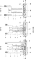
- FIGS. 13A and 13B are process diagram schematically showing one example of steps of the friction stir spot welding performed by the friction stir spot welding apparatus shown in FIG. 11 .
- FIGS. 14A and 14B is a process diagram schematically showing another example of steps of the friction stir spot welding performed by the friction stir spot welding apparatus shown in FIG. 11 .
- FIGS. 13A to 14B shows an example in which: the plate-shaped first workpiece 61 and the plate-shaped second workpiece 62 are used as the welded workpiece 60; and these workpieces 61 and 62 are laminated on each other and coupled to each other by spot welding.
- the first workpiece 61 and the second workpiece 62 are the same in thickness as each other, and the first workpiece 61 is placed on the backing structure 56.
- the first workpiece 61 is higher in tensile strength than the second workpiece 62 and is placed on the backing structure 56.
- FIGS. 13A to 14B part of the friction stir spot welding apparatus 50 is not shown.
- Arrows r indicate the rotational directions of the pin 11 and the shoulder 12
- block arrows F indicate directions of forces applied to the first workpiece 61 and the second workpiece 62.
- FIGS. 13A to 14B Although forces are applied to the first workpiece 61 and the second workpiece 62 also from the backing structure 56, such forces are not shown in FIGS. 13A to 14B for convenience of explanation.
- the shoulder 12 is shown by cross hatching to clearly distinguish between the pin 11 and the clamp structure 13.
- a worker places the welded workpiece 60 on the supporting surface 56a of the backing structure 56.
- the worker manipulates the inputter 32 to input execution of welding of the welded workpiece 60 to the controller 51.
- a robot may place the welded workpiece 60 on the supporting surface 56a of the backing structure 56.
- the controller 51 drives the rotary driver 57 to rotate the pin 11 and the shoulder 12 at a preset and predetermined first rotational frequency (for example, 200 to 3,000 rpm) (see Step (1) in each of FIGS. 13A and 14A ).
- a preset and predetermined first rotational frequency for example, 200 to 3,000 rpm
- the controller 51 makes the pin 11, the shoulder 12, and the clamp structure 13 approach the welded workpiece 60 and brings the tip end surface 11a of the pin 11, the tip end surface 12a of the shoulder 12, and the tip end surface 13a of the clamp structure 13 (not shown in FIGS. 13A to 14B ) into contact with the front surface 60c of the welded workpiece 60 (see Step (2) in each of FIGS. 13A and 14A ).
- the controller 51 controls the advance-retreat driver 53 (shoulder driver 532) such that the pin 11, the shoulder 12, and the clamp structure 13 press the welded workpiece 60 by a preset and predetermined first pressing force (for example, a predetermined value within a range of 3 kN to 10 kN) as a whole.
- a preset and predetermined first pressing force for example, a predetermined value within a range of 3 kN to 10 kN
- first workpiece 61 and the second workpiece 62 are sandwiched by the clamp structure 13 and the backing structure 56, and the clamp structure 13 is biased toward the front surface 60c of the welded workpiece 60 by the contraction of the clamp driver 41 to generate clamping force.
- the front surface 60c of the welded workpiece 60 is subjected to "preheating." With this, a constituent material at a contact region of the welded workpiece 60 is softened by heat generated by friction, and thus, the plastically flowing portion 60a is generated in the vicinity of the front surface 60c of the welded workpiece 60.
- the controller 51 drives the advance-retreat driver 53 such that the tip end surface 11a of the pin 11 sinks relative to the tip end surface 12a of the shoulder 12.
- the controller 51 may drive the advance-retreat driver 53 (pin driver 531) such that the pin 11 separates from the welded workpiece 60.
- the controller 51 may drive the advance-retreat driver 53 (shoulder driver 532) such that the shoulder 12 is pressed in the welded workpiece 60.
- Step (3) of FIG. 13A a softened part of the welded workpiece 60 extends from the first workpiece 61 to the second workpiece 62, and the volume of the plastically flowing portion 60a increases. Moreover, a softened material of the plastically flowing portion 60a is pushed away by the shoulder 12 to flow from a position right under the shoulder 12 to a position right under the pin 11. Therefore, the pin 11 retreats and moves upward relative to the shoulder 12. On this account, upward force F acts on the pin 11 in some cases.
- the shoulder 12 is configured such that the material softened by the plastic flow flows in the advancing direction (lower direction) of the shoulder 12.
- the hook 66 is formed so as to be directed in the advancing direction of the shoulder 12.
- Step (3) of FIG. 14A when the first workpiece 61 is higher in tensile strength than the second workpiece 62, the hook 66 is formed at the first workpiece 61 which has not yet been subjected to the welding.
- the controller 51 acquires the positional information of the tip end portion of the shoulder 12 from the position detector 33. Then, the controller 51 determines whether or not the positional information of the tip end portion of the shoulder 12 acquired in Step S104 has reached the preset and predetermined first position.
- the controller 51 drives the advance-retreat driver 53 (pin driver 531) such that the pin 11 advances toward the welded workpiece 60, or the controller 51 drives the advance-retreat driver 53 (shoulder driver 532) such that the shoulder 12 separates from the welded workpiece 60.
- the controller 51 controls the advance-retreat driver 53 such that almost no level difference is generated between the tip end surface 11a of the pin 11 and the tip end surface 12a of the shoulder 12 (the tip end surface 11a of the pin 11 and the tip end surface 12a of the shoulder 12 are flush with each other) (see Step (5) in each of FIGS. 13B and 14B ).
- the front surface 60c of the welded workpiece 60 is shaped, and a substantially flat surface where recesses are not practically generated is obtained.
- the controller 51 drives the advance-retreat driver 53 such that the pin 11, the shoulder 12, and the clamp structure 13 separate from the welded workpiece 60 (Step S108). Then, the controller 51 controls the rotary driver 57 to stop the rotation of the pin 11 and the shoulder 12 (see Step (6) in each of FIGS. 13B and 14B ) and terminates the friction stir spot welding (step of welding the welded workpiece 60).
- the shoulder 12 is configured such that the material softened by the plastic flow flows in the advancing direction (lower direction) of the shoulder 12.
- the hook 66 is formed so as to be directed in the advancing direction of the shoulder 12. More specifically, when the pin 11 moves in the retreating direction, the hook 66 is slightly pulled in the retreating direction. However, since the hook 66 is deeply pushed inside in the advancing direction, the hook 66 is formed so as to be directed in the advancing direction of the shoulder 12 as a whole.
- the direction of the hook 66 is determined based on the direction of the tip end portion of the hook 66. Therefore, when part of the hook 66 is directed in an upper direction, but the tip end portion of the hook is formed so as to be directed in the lower direction, it is determined that the hook 66 is formed so as to be directed in the lower direction.
- the welding strength of the welded workpiece 60 is made higher than the welding strength of the welded workpiece welded by using the conventional friction stir spot welding apparatus.
- the tip end portion of the first groove 21 is formed at a position away from the tip end surface of the shoulder 12 toward the base end portion of the shoulder 12.
- the shoulder 12 may be configured such that when the shoulder 12 advances while rotating in the welded workpiece 60, the material softened by the plastic flow flows in the advancing direction of the shoulder 12.
- the shape of the shoulder 12 is not limited to the above shape.
- suitable recesses and/or projections may be provided on the outer peripheral surface of the tip end portion of the shoulder 12.
- each of the recesses and/or the projections may be formed so as to include such an inclined portion that a part (for example, the front end part 21a) thereof in the rotational direction of the shoulder 12 is located closer to the base end of the shoulder 12 than another part (for example, the rear end part 21b) thereof in the rotational direction of the shoulder 12.
- the inclined portion may be formed in a linear shape, a curved shape, or a stair shape.
- the second grooves are formed on the tip end surface of the shoulder.
- each second groove may be formed such that a bottom surface thereof is inclined.
- FIG. 15 is a schematic diagram showing a schematic configuration of the friction stir spot welding apparatus according to Modified Example 1 of Embodiment 3.
- FIG. 16 is a perspective view schematically showing the tip end portion of the shoulder of the friction stir spot welding apparatus shown in FIG. 15 .
- An upper-lower direction in FIG. 15 is shown as an upper-lower direction of the friction stir spot welding apparatus.
- the friction stir spot welding apparatus 50 according to Modified Example 1 of Embodiment 3 is the same in basic configuration as the friction stir spot welding apparatus 50 according to Embodiment 3 but is different from the friction stir spot welding apparatus 50 according to Embodiment 3 in that the second grooves 22 are formed on the tip end surface 12a of the shoulder 12 so as to extend in the radial direction.
- the second grooves 22 are formed such that bottom surfaces 22a thereof are inclined.
- each of the bottom surfaces 22a is inclined such that a front end part 221 thereof in the rotational direction of the shoulder 12 is located closer to the base end of the shoulder 12 than a rear end part 222 thereof in the rotational direction of the shoulder 12.
- the material softened by the plastic flow is made to flow in the advancing direction (lower direction) of the shoulder 12. Therefore, the softened material is made to flow in the advancing direction (lower direction) of the shoulder 12 more than the friction stir spot welding apparatus 50 according to Embodiment 3.
- the welding strength of the welded workpiece 60 is made higher than the welding strength of the welded workpiece welded by using the friction stir spot welding apparatus 50 according to Embodiment 3.
- a friction stir spot welding apparatus is a friction stir spot welding apparatus that performs friction stir spot welding with respect to a welded workpiece including a first workpiece and a second workpiece.
- the friction stir spot welding apparatus includes: a pin that is columnar; a shoulder that is cylindrical, the pin being within the shoulder; a rotary driver that rotates the pin and the shoulder about an axis that coincides with a center axis of the pin; and an advance-retreat driver that advances and retreats the pin and the shoulder along the axis.
- the shoulder is configured such that when the shoulder advances in the welded workpiece, a material softened by plastic flow flows in an advancing direction of the shoulder.
- the shoulder may be configured such that a hook of the welded workpiece is formed so as to be directed in the advancing direction of the shoulder.
- a second groove may be formed on a tip end surface of the shoulder so as to extend in a radial direction of the shoulder or a direction along a straight line segment joining two points on a circle of the tip end surface of the shoulder.
- the second groove may be formed such that a bottom surface thereof is inclined.
- the welded workpiece according to Embodiment 4 may be a welded workpiece subjected to the friction stir spot welding by any one of the friction stir spot welding apparatuses according to Embodiment 4.
- tensile strength of the first workpiece may be higher than that of the second workpiece, and the hook may be formed at the first workpiece which has not yet been subjected to the welding.
- FIG. 17 is a schematic diagram showing a schematic configuration of the friction stir spot welding apparatus according to Embodiment 4.
- FIG. 18 is a perspective view schematically showing the tip end portion of the shoulder of the friction stir spot welding apparatus shown in FIG. 17 .
- An upper-lower direction in FIG. 17 is shown as an upper-lower direction of the friction stir spot welding apparatus.
- the friction stir spot welding apparatus 50 according to Embodiment 4 is the same in basic configuration as the friction stir spot welding apparatus 50 according to Embodiment 3 but is different from the friction stir spot welding apparatus 50 according to Embodiment 3 in that instead of the first grooves 21, the second grooves 22 are formed on the tip end surface 12a of the shoulder 12 so as to extend in the radial direction.
- the second grooves 22 are formed such that the bottom surfaces 22a thereof are inclined.
- each of the bottom surfaces 22a is inclined such that the front end part 221 thereof in the rotational direction of the shoulder 12 is located closer to the base end of the shoulder 12 than the rear end part 222 thereof in the rotational direction of the shoulder 12.
- the material softened by the plastic flow is made to flow in the advancing direction (lower direction) of the shoulder 12. Therefore, the softened material is made to flow in the advancing direction (lower direction) of the shoulder 12, and as shown in Test Examples described above, the welding strength of the welded workpiece 60 is made higher.
- the second grooves 22 are formed so as to extend linearly in the radial direction.
- the second grooves 22 may be formed so as to extend curvedly in the radial direction or may be formed so as to extend linearly or curvedly in the direction along the straight line segment joining two points on the circle of the tip end surface of the shoulder 12.
- the friction stir spot welding apparatus is a friction stir spot welding apparatus that performs friction stir spot welding with respect to a welded workpiece including a first workpiece and a second workpiece.
- the friction stir spot welding apparatus includes: a pin that is columnar; a shoulder that is cylindrical, the pin being within the shoulder; a rotary driver that rotates the pin and the shoulder about an axis that coincides with a center axis of the pin; and an advance-retreat driver that advances and retreats the pin and the shoulder along the axis.
- the shoulder is configured such that when the shoulder advances in the welded workpiece, a material softened by plastic flow flows in a retreating direction of the shoulder.
- the shoulder may be configured such that a hook of the welded workpiece is formed so as to be directed in the retreating direction of the shoulder.
- a first groove may be formed on an outer peripheral surface of a tip end portion of the shoulder, and the first groove may be formed such that a rear end thereof in a rotational direction of the shoulder is located closer to a base end of the shoulder than a front end thereof in the rotational direction of the shoulder.
- the welded workpiece according to Embodiment 5 may be a welded workpiece subjected to the friction stir spot welding by any one of the friction stir spot welding apparatuses according to Embodiment 5.
- tensile strength of the first workpiece may be higher than that of the second workpiece, and the hook may be formed at the first workpiece which has not yet been subjected to the welding.
- the welded workpiece according to Embodiment 5 is a welded workpiece subjected to the friction stir spot welding by the friction stir spot welding apparatus and includes the first workpiece and the second workpiece, and the hook is formed in the first workpiece which has not yet been subjected to the welding.
- FIG. 19 is a schematic diagram showing a schematic configuration of the friction stir spot welding apparatus according to Embodiment 5.
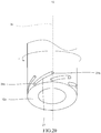
- FIG. 20 is a perspective view schematically showing the tip end portion of the shoulder of the friction stir spot welding apparatus shown in FIG. 19 .
- An upper-lower direction in FIG. 19 is shown as an upper-lower direction of the friction stir spot welding apparatus.
- the friction stir spot welding apparatus 50 according to Embodiment 5 is the same in basic configuration as the friction stir spot welding apparatus 50 according to Embodiment 1 but is different from the friction stir spot welding apparatus 50 according to Embodiment 1 regarding the shape of the shoulder 12. Since the control configuration of the friction stir spot welding apparatus 50 according to Embodiment 5 is the same as that of the friction stir spot welding apparatus 50 according to Embodiment 1, a detailed explanation thereof is omitted.
- the shoulder 12 is configured such that when the shoulder 12 advances in the welded workpiece 60, the material softened by the plastic flow flows in the retreating direction of the shoulder 12 (see FIG. 21A ).
- the shoulder 12 is configured such that the hook 66 is formed at the welded workpiece 60 so as to be directed in the retreating direction of the shoulder 12.
- the first grooves 21 formed on the outer peripheral surface of the tip end portion of the shoulder 12 are formed such that the front end parts 21a thereof in the rotational direction of the shoulder 12 are located closer to the tip end of the shoulder than the rear end parts 21b thereof in the rotational direction of the shoulder 12.
- the first grooves 21 are formed on the outer peripheral surface of the tip end portion of the shoulder 12 such that the front end parts 21a thereof are located closer to the tip end of the shoulder 12, and the rear end parts 21b thereof are located closer to the base end of the shoulder 12.
- the first grooves 21 are formed so as to cover the entire outer peripheral surface of the shoulder 12.
- the present embodiment is not limited to this.
- one first groove 21 may be formed in a spiral shape so as to cover the entire outer peripheral surface of the shoulder 12.
- recesses and/or projections may be provided on the outer peripheral surface of the tip end portion of the shoulder 12 so as to be lined up on a straight line.
- the shoulder 12 may be configured such that when the shoulder 12 advances while rotating in the welded workpiece 60, the material softened by the plastic flow flows in the retreating direction of the shoulder 12.
- the shape of the shoulder 12 is not limited to the above shape.
- suitable recesses and/or projections may be provided on the outer peripheral surface of the tip end portion of the shoulder 12.
- each of the recesses and/or the projections may be formed so as to include such an inclined portion that a part (for example, a rear end part) thereof in the rotational direction of the shoulder 12 is located closer to the base end of the shoulder 12 than another part (for example, a front end part) thereof in the rotational direction of the shoulder 12.
- the inclined portion may be formed in a linear shape, a curved shape, or a stair shape.
- FIGS. 21A and 21B is a process diagram schematically showing one example of steps of the friction stir spot welding performed by the friction stir spot welding apparatus shown in FIG. 19 .
- FIGS. 21A and 21B shows an example in which: the plate-shaped first workpiece 61 and the plate-shaped second workpiece 62 are used as the welded workpiece 60; and these workpieces 61 and 62 are laminated on each other and coupled to each other by spot welding.
- the first workpiece 61 is higher in tensile strength than the second workpiece 62 and is placed on the backing structure 56.
- FIGS. 21A and 21B part of the friction stir spot welding apparatus 50 is not shown.
- Arrows r indicate the rotational directions of the pin 11 and the shoulder 12
- block arrows F indicate directions of forces applied to the first workpiece 61 and the second workpiece 62.
- FIGS. 21A and 21B Although forces are applied to the first workpiece 61 and the second workpiece 62 also from the backing structure 56, such forces are not shown in FIGS. 21A and 21B for convenience of explanation.
- the shoulder 12 is shown by cross hatching to clearly distinguish between the pin 11 and the clamp structure 13.
- a worker places the welded workpiece 60 on the supporting surface 56a of the backing structure 56.
- the worker manipulates the inputter 32 to input execution of welding of the welded workpiece 60 to the controller 51.
- a robot may place the welded workpiece 60 on the supporting surface 56a of the backing structure 56.
- the controller 51 drives the rotary driver 57 to rotate the pin 11 and the shoulder 12 at a preset and predetermined first rotational frequency (for example, 200 to 3,000 rpm) (see Step (1) in FIG. 21A ).
- a preset and predetermined first rotational frequency for example, 200 to 3,000 rpm
- the controller 51 makes the pin 11, the shoulder 12, and the clamp structure 13 approach the welded workpiece 60 and brings the tip end surface 11a of the pin 11, the tip end surface 12a of the shoulder 12, and the tip end surface 13a of the clamp structure 13 (not shown in FIGS. 21A and 21B ) into contact with the front surface 60c of the welded workpiece 60 (see Step (2) in FIG. 21A ).
- the controller 51 controls the advance-retreat driver 53 (shoulder driver 532) such that the pin 11, the shoulder 12, and the clamp structure 13 press the welded workpiece 60 by a preset and predetermined first pressing force (for example, a predetermined value within a range of 3 kN to 10 kN) as a whole.
- a preset and predetermined first pressing force for example, a predetermined value within a range of 3 kN to 10 kN
- first workpiece 61 and the second workpiece 62 are sandwiched by the clamp structure 13 and the backing structure 56, and the clamp structure 13 is biased toward the front surface 60c of the welded workpiece 60 by the contraction of the clamp driver 41 to generate clamping force.
- the front surface 60c of the welded workpiece 60 is subjected to "preheating." With this, a constituent material at a contact region of the first workpiece 61 is softened by heat generated by friction, and thus, the plastically flowing portion 60a is generated in the vicinity of the front surface 60c of the welded workpiece 60.
- the controller 51 drives the advance-retreat driver 53 such that the tip end surface 11a of the pin 11 sinks relative to the tip end surface 12a of the shoulder 12.
- the controller 51 may drive the advance-retreat driver 53 (pin driver 531) such that the pin 11 separates from the welded workpiece 60.
- the controller 51 may drive the advance-retreat driver 53 (shoulder driver 532) such that the shoulder 12 is pressed in the welded workpiece 60.
- Step (3) in FIG. 21A a softened part of the welded workpiece 60 extends from the first workpiece 61 at the upper side to the second workpiece 62 at the lower side, and the volume of the plastically flowing portion 60a increases. Moreover, a softened material of the plastically flowing portion 60a is pushed away by the shoulder 12 to flow from a position right under the shoulder 12 to a position right under the pin 11. Therefore, the pin 11 retreats and moves upward relative to the shoulder 12.
- the shoulder 12 is configured such that the material softened by the plastic flow flows in the retreating direction (upper direction) of the shoulder 12.
- the hook 66 is formed so as to be directed in the retreating direction of the shoulder 12.
- the controller 51 acquires the positional information of the tip end portion of the shoulder 12 from the position detector 33. Then, the controller 51 determines whether or not the positional information of the tip end portion of the shoulder 12 acquired in Step S104 has reached the preset and predetermined first position.
- the controller 51 drives the advance-retreat driver 53 (pin driver 531) such that the pin 11 advances toward the welded workpiece 60, or the controller 51 drives the advance-retreat driver 53 (shoulder driver 532) such that the shoulder 12 separates from the welded workpiece 60.
- the pin 11 gradually advances toward the first workpiece 61, and the shoulder 12 retreats from the first workpiece 61 (see Step (4) in FIG. 21B ).
- the softened part of the plastically flowing portion 60a flows from the position right under the pin 11 to the position right under the shoulder 12 (to a recess generated by press-in of the shoulder 12).
- the controller 51 controls the advance-retreat driver 53 such that almost no level difference is generated between the tip end surface 11a of the pin 11 and the tip end surface 12a of the shoulder 12 (the tip end surface 11a of the pin 11 and the tip end surface 12a of the shoulder 12 are flush with each other) (see Step (5) in FIG. 21B ).
- the front surface 60c of the welded workpiece 60 is shaped, and a substantially flat surface where recesses are not practically generated is obtained.
- the controller 51 drives the advance-retreat driver 53 such that the pin 11, the shoulder 12, and the clamp structure 13 separate from the welded workpiece 60 (Step S108).
- the controller 51 controls the rotary driver 57 to stop the rotation of the pin 11 and the shoulder 12 (see Step (6) in FIG. 21B ) and terminates the friction stir spot welding (step of welding the welded workpiece 60).
- the shoulder 12 is configured such that the material softened by the plastic flow flows in the retreating direction (upper direction) of the shoulder 12.
- the hook 66 is formed so as to be directed in the retreating direction of the shoulder 12, and as shown in Test Examples described below, the hook can be formed at the first workpiece 61 having high tensile strength so as to be larger in height than the hook formed by the conventional shoulder 12 that does not include the first grooves 21. Therefore, the welding strength of the welded workpiece 60 is made higher than the welding strength of the welded workpiece welded by using the conventional friction stir spot welding apparatus.
- the friction stir spot welding apparatus 50 according to Embodiment 3 was used as a friction stir spot welding apparatus of Example 1, and the friction stir spot welding apparatus of Example 1 executed the friction stir spot welding.
- the friction stir spot welding apparatus 50 according to Modified Example 1 of Embodiment 3 was used as a friction stir spot welding apparatus of Example 2, and the friction stir spot welding apparatus of Example 2 executed the friction stir spot welding.
- the friction stir spot welding apparatus 50 according to Embodiment 4 was used as a friction stir spot welding apparatus of Example 3, and the friction stir spot welding apparatus of Example 3 executed the friction stir spot welding.
- the friction stir spot welding apparatus 50 according to Embodiment 5 was used as a friction stir spot welding apparatus of Example 4, and the friction stir spot welding apparatus of Example 4 executed the friction stir spot welding.
- a friction stir spot welding apparatus of Comparative Example 1 executed the friction stir spot welding by using a shoulder 12 that is the same in configuration as the conventional shoulder 12 and does not include the first grooves 21 and the second grooves 22.
- the welded workpieces 60 welded by the friction stir spot welding apparatuses of Comparative Example 1 and Examples 1 and 2 were subjected to the cross tension test (JIS Z 3137) under such conditions that: an aluminum plate (2024-T8) having a thickness of 1.6 mm was used as the second workpiece 62; an aluminum plate (2024-T3) having a thickness of 3.0 mm was used as the first workpiece 61; and the first workpiece 61 was placed on the backing structure 56.
- JIS Z 3137 cross tension test
- FIGS. 22A and 22B show pictures of sections of the welded workpiece which has been subjected to the friction stir spot welding by using the friction stir spot welding apparatus of Example 1 and has not yet been subjected to the cross tension test, and FIG. 22B shows an enlarged picture of a region (B) shown in FIG. 22A .
- FIGS. 23A and 23B show pictures of sections of the welded workpiece which has been subjected to the cross tension test after being subjected to the friction stir spot welding by using the friction stir spot welding apparatus of Example 1, and FIG. 23B shows an enlarged picture of a region (B) shown in FIG. 23A .
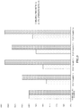
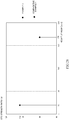
- FIG. 24 is a graph showing results of the cross tension test of the welded workpieces subjected to the friction stir spot welding by using the friction stir spot welding apparatuses of Comparative Example 1 and Examples 1 and 2 and also showing the heights of the hooks.
- each of the results of the cross tension test when the friction stir spot welding apparatus of Comparative Example 1 was used is shown as 100%, and based on this, the results of the cross tension test when the friction stir spot welding apparatuses of Examples 1 and 2 were used to perform the friction stir spot welding are shown.
- a portion at an upper side of a contact surface between the first workpiece 61 and the second workpiece 62 is shown as a positive side, and a portion at a lower side of the contact surface between the first workpiece 61 and the second workpiece 62 is shown as a negative side.
- the height of the hook was -121 ⁇ m.
- the height of the hook was -29 ⁇ m.
- the height of the hook was 117 ⁇ m.
- the welded workpieces 60 welded by the friction stir spot welding apparatuses of Comparative Example 1 and Example 1 were subjected to the cross tension test (JIS Z 3137) under such conditions that: an aluminum plate (2024-T3) having a thickness of 3.0 mm was used as the second workpiece 62; an aluminum plate (2024-T3) having a thickness of 3.0 mm was used as the first workpiece 61; and the first workpiece 61 was placed on the backing structure 56.
- FIGS. 25A and 25B show pictures of sections of the welded workpiece subjected to the friction stir spot welding by using the friction stir spot welding apparatus of Comparative Example 1.
- FIG. 25A shows the picture before the cross tension test
- FIG. 25B shows the picture after the cross tension test.
- FIG. 25A shows an enlarged view of the hook and its vicinity.
- FIGS. 26A and 26B show pictures of sections of the welded workpiece subjected to the friction stir spot welding by using the friction stir spot welding apparatus of Example 1.
- FIG. 26A shows the picture before the cross tension test
- FIG. 26B shows the picture after the cross tension test
- FIG. 26A is an enlarged view of the hook and its vicinity.
- the hook can be formed so as to be directed in the advancing direction of the shoulder 12 by forming the first grooves 21 such that the front end parts 21a thereof in the rotational direction of the shoulder 12 are located closer to the base end of the shoulder than the rear end parts 21b thereof in the rotational direction of the shoulder 12.
- these results also indicate that by selecting the shape of the shoulder 12, the workpiece that breaks in the welded workpiece 60 can be selected.
- the welded workpieces 60 welded by the friction stir spot welding apparatuses of Example 3 and Comparative Example 1 were subjected to the cross tension test (JIS Z 3137) under such conditions that: an aluminum plate (2024-T3) having a thickness of 3.0 mm was used as the second workpiece 62; an aluminum plate (2024-T3) having a thickness of 3.0 mm was used as the first workpiece 61; and the first workpiece 61 was placed on the backing structure 56.
- FIGS. 27A and 27B show pictures of sections of the welded workpiece subjected to the friction stir spot welding by using the friction stir spot welding apparatus of Example 3, and
- FIG. 27B shows an enlarged picture of a region (B) shown in FIG. 27A .
- FIG. 28 is a graph showing results of the cross tension test of the welded workpieces subjected to the friction stir spot welding by using the friction stir spot welding apparatuses of Comparative Example 1 and Example 3 and also showing the heights of the hooks.
- each of the results of the cross tension test when the friction stir spot welding apparatus of Comparative Example 1 was used is shown as 100%, and based on this, the results of the cross tension test when the friction stir spot welding apparatus of Example 3 was used to perform the friction stir spot welding are shown.
- the height of the hook was made smaller than the height of the hook in the welded workpiece 60 subjected to the friction stir spot welding by using the friction stir spot welding apparatus of Comparative Example 1, and the welding strength was made higher than the welding strength of the welded workpiece 60 subjected to the friction stir spot welding by using the friction stir spot welding apparatus of Comparative Example 1.
- the welded workpieces 60 welded by the friction stir spot welding apparatuses of Comparative Example 1 and Example 4 were subjected to the cross tension test (JIS Z 3137) under such conditions that: an aluminum plate (2024-T3) having a thickness of 3.0 mm was used as the second workpiece 62; an aluminum plate (2024-T3) having a thickness of 5.0 mm was used as the first workpiece 61; and the second workpiece 62 was placed on the backing structure 56.
- JIS Z 3137 cross tension test
- FIGS. 29A and 29B show pictures of sections of the welded workpieces subjected to the friction stir spot welding by using the friction stir spot welding apparatuses of Comparative Example 1 and Example 4.
- FIG. 29A shows a picture of a section of the welded workpiece subjected to the friction stir spot welding by using the friction stir spot welding apparatus of Comparative Example 1
- FIG. 29B shows a picture of a section of the welded workpiece subjected to the friction stir spot welding by using the friction stir spot welding apparatus of Example 4.
- FIG. 30 is a graph showing results of the cross tension test of the welded workpieces subjected to the friction stir spot welding by using the friction stir spot welding apparatuses of Comparative Example 1 and Example 4 and also showing the heights of the hooks.
- each of the results of the cross tension test when the friction stir spot welding apparatus of Comparative Example 1 was used is shown as 100%, and based on this, the results of the cross tension test when the friction stir spot welding apparatus of Example 4 was used to perform the friction stir spot welding are shown.
- the height of the hook 66 was made larger than the height of the hook in the welded workpiece 60 subjected to the friction stir spot welding by using the friction stir spot welding apparatus of Comparative Example 1, and the welding strength was made higher than the welding strength of the welded workpiece 60 subjected to the friction stir spot welding by using the friction stir spot welding apparatus of Comparative Example 1.
- the friction stir spot welding apparatus of the present invention is useful since the welding time is made shorter than those of the conventional friction stir spot welding apparatuses.
Landscapes
- Engineering & Computer Science (AREA)
- Mechanical Engineering (AREA)
- Pressure Welding/Diffusion-Bonding (AREA)
Abstract
Description
- The present invention relates to a friction stir spot welding apparatus, a welded workpiece subjected to friction stir spot welding, and a shoulder.
- In transportation machines, such as automobiles, railcars, and aircrafts, resistance spot welding or rivet joining has been used to couple metal materials to each other. However, in recent years, a method (friction stir spot welding method) of welding metal materials by utilizing frictional heat is gathering attention (see
PTL 1, for example). - According to the friction stir spot welding method disclosed in
PTL 1, a substantially columnar pin and a substantially cylindrical shoulder including a hollow into which the pin is inserted are used to weld a welded workpiece, and a tool driver that operates (drives) the pin and the shoulder (rotary tool; welding tool) is controlled as below. - To be specific, the tool driver is controlled to reduce an absolute value of a tool average position Tx defined by a formula "Ap·Pp+As·Ps = Tx", where Ap denotes a sectional area of a tip end surface of the pin, As denotes a sectional area of a tip end surface of the shoulder, Pp denotes a press-in depth of the pin when the pin is pressed in the surface of the welded workpiece, and Ps denotes a press-in depth of the shoulder when the shoulder is pressed in the surface of the welded workpiece.
- With this, satisfactory welding quality can be realized with a preferable degree of accuracy in accordance with welding conditions, and the generation of internal void defects can be prevented or suppressed.
- PTL 1:
Japanese Laid-Open Patent Application Publication No. 2012-196682 - However, according to the friction stir spot welding method disclosed in
PTL 1, there is still room for improvement in terms of a reduction in welding time of the welded workpiece. Moreover, according to the friction stir spot welding method disclosed inPTL 1, there is still room for improvement in terms of welding strength of the welded workpiece. - The present invention was made to solve the above conventional problems, and a first object of the present invention is to provide a friction stir spot welding apparatus that can make a welding time shorter than welding times of conventional friction stir spot welding apparatuses. Moreover, a second object of the present invention is to provide a friction stir spot welding apparatus that can make welding strength higher than welding strength of welded workpieces welded by the conventional friction stir spot welding apparatuses and also provide a welded workpiece that has higher welding strength than the welded workpieces welded by the conventional friction stir spot welding apparatuses.
- In order to solve the above problems, a friction stir spot welding apparatus according to the present invention includes: a pin that is columnar; a shoulder that is cylindrical, the pin being within the shoulder; a rotary driver that rotates the pin and the shoulder about an axis that coincides with a center axis of the pin; and an advance-retreat driver that advances and retreats the pin and the shoulder along the axis. A first groove is formed at a tip end portion of an outer peripheral surface of the shoulder so as to extend in a direction along the center axis of the pin.
- With this, the welding time is made shorter than those of the conventional friction stir spot welding apparatuses.
- Moreover, a friction stir spot welding apparatus according to the present invention includes: a pin that is columnar; a shoulder that is cylindrical, the pin being within the shoulder; a rotary driver that rotates the pin and the shoulder about an axis that coincides with a center axis of the pin; and an advance-retreat driver that advances and retreats the pin and the shoulder along the axis. A second groove is formed on a tip end surface of the shoulder so as to extend in a radial direction of the shoulder.
- With this, the welding time is made shorter than those of the conventional friction stir spot welding apparatuses.
- Moreover, a friction stir spot welding apparatus according to the present invention is a friction stir spot welding apparatus that performs friction stir spot welding with respect to a welded workpiece including a first workpiece and a second workpiece. The friction stir spot welding apparatus includes: a pin; a shoulder that is hollow, the pin being within the shoulder; a rotary driver that rotates the pin and the shoulder about an axis extending in a longitudinal direction of the pin and a longitudinal direction of the shoulder; and an advance-retreat driver that advances and retreats the pin and the shoulder along the axis. The shoulder is configured such that when the shoulder advances while rotating in the welded workpiece, a material softened by plastic flow flows in an advancing direction of the shoulder or a retreating direction of the shoulder.
- With this, the welding strength of the welded workpiece is made higher than the welding strength of the welded workpiece welded by using the conventional friction stir spot welding apparatus.
- Moreover, a welded workpiece according to the present invention is a welded workpiece subjected to friction stir spot welding by the above friction stir spot welding apparatus.
- With this, the welded workpiece having higher welding strength than the welded workpiece welded by the conventional friction stir spot welding apparatus is obtained.
- Furthermore, a welded workpiece according to the present invention is a welded workpiece subjected to friction stir spot welding by a friction stir spot welding apparatus. The welded workpiece includes: a first workpiece; a second workpiece; and a hook in the first workpiece or the second workpiece.
- With this, the welded workpiece having higher welding strength than the welded workpiece welded by the conventional friction stir spot welding apparatus is obtained.
- The above object, other objects, features, and advantages of the present invention will be made clear by the following detailed explanation of preferred embodiments with reference to the attached drawings.
- According to the friction stir spot welding apparatus of the present invention, the welding time is made shorter than those of the conventional friction stir spot welding apparatuses. Moreover, according to the friction stir spot welding apparatus of the present invention, the welding strength of the welded workpiece is made higher than the welding strength of the welded workpiece welded by using the conventional friction stir spot welding apparatus. Furthermore, according to the welded workpiece of the present invention, the welded workpiece having higher welding strength than the welded workpiece welded by the conventional friction stir spot welding apparatus is obtained.
-
-
FIG. 1 is a schematic diagram showing a schematic configuration of a friction stir spot welding apparatus according toEmbodiment 1. -
FIG. 2 is a perspective view schematically showing a tip end portion of a shoulder of the friction stir spot welding apparatus shown inFIG. 1 . -
FIG. 3 is a block diagram schematically showing a control configuration of the friction stir spot welding apparatus shown inFIG. 1 . -
FIG. 4 is a flow chart showing one example of an operation of the friction stir spot welding apparatus according toEmbodiment 1. -
FIG. 5A is a process diagram schematically showing one example of steps of friction stir spot welding performed by the friction stir spot welding apparatus shown inFIG. 1 . -
FIG. 5B is a process diagram schematically showing one example of steps of the friction stir spot welding performed by the friction stir spot welding apparatus shown inFIG. 1 . -
FIG. 6 is a perspective view schematically showing a major component (the tip end portion of the shoulder) of the friction stir spot welding apparatus according to Modified Example 1 ofEmbodiment 1. -
FIG. 7 is a schematic diagram showing a schematic configuration of the friction stir spot welding apparatus according toEmbodiment 2. -
FIG. 8 is a perspective view schematically showing the tip end portion of the shoulder of the friction stir spot welding apparatus shown inFIG. 7 . -
FIG. 9 is a graph showing welding times as results of the friction stir spot welding performed by using the friction stir spot welding apparatuses of Comparative Example and Test Examples 1 to 4 and also showing results of a cross tension test. -
FIG. 10A shows pictures of sections of the welded workpieces subjected to the friction stir spot welding by using the friction stir spot welding apparatuses of Comparative Example and Test Examples 1 to 4. -
FIG. 10A shows pictures of sections of the welded workpieces subjected to the friction stir spot welding by using the friction stir spot welding apparatuses of Comparative Example and Test Examples 1 to 4. -
FIG. 11 is a schematic diagram showing a schematic configuration of the friction stir spot welding apparatus according toEmbodiment 3. -
FIG. 12 is a perspective view schematically showing the tip end portion of the shoulder of the friction stir spot welding apparatus shown inFIG. 11 . -
FIG. 13A is a process diagram schematically showing one example of steps of the friction stir spot welding performed by the friction stir spot welding apparatus shown inFIG. 11 . -
FIG. 13B is a process diagram schematically showing the one example of steps of the friction stir spot welding performed by the friction stir spot welding apparatus shown inFIG. 11 . -
FIG. 14A is a process diagram schematically showing another example of steps of the friction stir spot welding performed by the friction stir spot welding apparatus shown inFIG. 11 . -
FIG. 14B is a process diagram schematically showing the another example of steps of the friction stir spot welding performed by the friction stir spot welding apparatus shown inFIG. 11 . -
FIG. 15 is a schematic diagram showing a schematic configuration of the friction stir spot welding apparatus according to Modified Example 1 ofEmbodiment 3. -
FIG. 16 is a perspective view schematically showing the tip end portion of the shoulder of the friction stir spot welding apparatus shown inFIG. 15 . -
FIG. 17 is a schematic diagram showing a schematic configuration of the friction stir spot welding apparatus according toEmbodiment 4. -
FIG. 18 is a perspective view schematically showing the tip end portion of the shoulder of the friction stir spot welding apparatus shown inFIG. 17 . -
FIG. 19 is a schematic diagram showing a schematic configuration of the friction stir spot welding apparatus according toEmbodiment 5. -
FIG. 20 is a perspective view schematically showing the tip end portion of the shoulder of the friction stir spot welding apparatus shown inFIG. 19 . -
FIG. 21A is a process diagram schematically showing one example of steps of the friction stir spot welding performed by the friction stir spot welding apparatus shown inFIG. 19 . -
FIG. 21B is a process diagram schematically showing the one example of steps of the friction stir spot welding performed by the friction stir spot welding apparatus shown inFIG. 19 . -
FIGS. 22A and 22B show pictures of sections of the welded workpiece subjected to the friction stir spot welding by using the friction stir spot welding apparatuses of Example 1. -
FIGS. 23A and 23B show pictures of sections of the welded workpiece which has been subjected to the cross tension test after being subjected to the friction stir spot welding by using the friction stir spot welding apparatus of Example 1. -
FIG. 24 is a graph showing results of the cross tension test performed with respect to the welded workpieces subjected to the friction stir spot welding by using the friction stir spot welding apparatuses of Comparative Example 1 and Examples 1 and 2 and also showing heights of hooks. -
FIGS. 25A and 25B show pictures of sections of the welded workpiece subjected to the friction stir spot welding by using the friction stir spot welding apparatus of Comparative Example 1. -
FIGS. 26A and 26B show pictures of sections of the welded workpiece subjected to the friction stir spot welding by using the friction stir spot welding apparatus of Example 1. -
FIGS. 27A and 27B show pictures of sections of the welded workpiece subjected to the friction stir spot welding by using the friction stir spot welding apparatus of Example 3. -
FIG. 28 is a graph showing results of the cross tension test performed with respect to the welded workpieces subjected to the friction stir spot welding by using the friction stir spot welding apparatuses of Comparative Example 1 and Example 3 and also showing the heights of the hooks. -
FIGS. 29A and 29B show pictures of sections of the welded workpieces subjected to the friction stir spot welding by using the friction stir spot welding apparatuses of Comparative Example 1 and Example 4. -
FIG. 30 is a graph showing results of the cross tension test performed with respect to the welded workpieces subjected to the friction stir spot welding by using the friction stir spot welding apparatuses of Comparative Example 1 and Example 4 and also showing the heights of the hooks. - Hereinafter, preferred embodiments of the present invention will be described with reference to the drawings. In the following description and the drawings, the same reference signs are used for the same or corresponding components, and the repetition of the same explanation is avoided. Moreover, in the drawings, components necessary to explain the present invention are shown, and the other component may be omitted. Furthermore, the present invention is not limited to the following embodiments.
- A friction stir spot welding apparatus according to
Embodiment 1 includes: a pin that is columnar; a shoulder that is cylindrical, the pin being within the shoulder; a rotary driver that rotates the pin and the shoulder about an axis that coincides with a center axis of the pin; and an advance-retreat driver that advances and retreats the pin and the shoulder along the axis. A first groove is formed at a tip end portion of an outer peripheral surface of the shoulder so as to extend in a direction along the center axis of the pin. - Hereinafter, one example of a friction stir spot welding apparatus according to
Embodiment 1 will be described in detail with reference to the drawings. -
FIG. 1 is a schematic diagram showing a schematic configuration of the friction stir spot welding apparatus according toEmbodiment 1.FIG. 2 is a perspective view schematically showing a tip end portion of a shoulder of the friction stir spot welding apparatus shown inFIG. 1 . An upper-lower direction inFIG. 1 is shown as an upper-lower direction of the friction stir spot welding apparatus. - As shown in
FIG. 1 , a friction stirspot welding apparatus 50 according toEmbodiment 1 includes apin 11, ashoulder 12, atool fixture 52, an advance-retreat driver 53, aclamp structure 13, abacking support 55, abacking structure 56, and arotary driver 57. - The
pin 11, theshoulder 12, thetool fixture 52, the advance-retreat driver 53, theclamp structure 13, and therotary driver 57 are disposed at an upper end portion of thebacking support 55 constituted by a C-shaped gun (C-shaped frame). Moreover, thebacking structure 56 is disposed at a lower end portion of thebacking support 55. Thepin 11, theshoulder 12, theclamp structure 13, and thebacking structure 56 are attached to thebacking support 55 at such positions that thepin 11, theshoulder 12, and theclamp structure 13 are opposed to thebacking structure 56. A weldedworkpiece 60 is arranged between thepin 11 and thebacking structure 56, between theshoulder 12 and thebacking structure 56, and between theclamp structure 13 and thebacking structure 56. - The
pin 11, theshoulder 12, and theclamp structure 13 are fixed to thetool fixture 52 constituted by arotary tool fixture 521 and aclamp fixture 522. Specifically, thepin 11 and theshoulder 12 are fixed to therotary tool fixture 521, and theclamp structure 13 is fixed to theclamp fixture 522 through aclamp driver 41. Therotary tool fixture 521 is supported by theclamp fixture 522 through therotary driver 57. Theclamp driver 41 is constituted by springs. - Moreover, the
pin 11, theshoulder 12, and theclamp structure 13 are driven by the advance-retreat driver 53 constituted by apin driver 531 and ashoulder driver 532, to advance and retreat in the upper-lower direction. - The
pin 11 is formed in a columnar shape. Although not shown inFIG. 1 in detail, thepin 11 is supported by therotary tool fixture 521. Thepin 11 may be supported by therotary tool fixture 521 through a linear motion bearing (not shown). - Moreover, the
pin 11 is rotated by therotary driver 57 about an axis Xr (rotation axis) that coincides with a center axis of thepin 11. Furthermore, thepin 11 can advance and retreat by thepin driver 531 in a direction indicated by an arrow PI, i.e., in a direction along the axis Xr (in the upper-lower direction inFIG. 1 ). Thepin driver 531 may apply pressure to thepin 11. For example, a mechanism that utilizes gas pressure, hydraulic pressure, a servomotor, or the like may be suitably used. - The
shoulder 12 is formed in a cylindrical shape including a hollow and is supported by therotary tool fixture 521. Thepin 11 is inserted into the hollow of theshoulder 12. In other words, theshoulder 12 is arranged so as to surround an outer peripheral surface of thepin 11. - Moreover, the
shoulder 12 is rotated by therotary driver 57 about the same axis Xr as thepin 11. Furthermore, the shoulder can advance and retreat by theshoulder driver 532 in a direction indicated by an arrow P2, i.e., in the direction along the axis Xr. Theshoulder driver 532 may apply pressure to theshoulder 12. For example, a mechanism that utilizes gas pressure, hydraulic pressure, a servomotor, or the like may be suitably used. - Furthermore,
first grooves 21 are formed on an outer peripheral surface of a tip end portion (lower end portion) of theshoulder 12 so as to extend from atip end surface 12a (tip end of the shoulder 12) (seeFIGS. 1 and2 ). Herein, thefirst grooves 21 are formed so as to extend in the direction along the axis Xr. However, thefirst grooves 21 are not limited to this and may be formed so as to extend in an oblique direction to the axis Xr. Moreover, herein, thefirst grooves 21 are provided at four positions. However, the present embodiment is not limited to this. Thefirst groove 21 may be provided at one position, or thefirst grooves 21 may be provided at plural positions (for example, two, six, or eight positions). - Herein, the tip ends of the
first grooves 21 coincide with the tip end of theshoulder 12. However, the present embodiment is not limited to this. The tip ends of thefirst grooves 21 may be located at a base end side (upper side) of the tip end of theshoulder 12. - A length of each
first groove 21 in a width direction (circumferential direction of the shoulder 12) may be 0.3 mm or more or 0.5 mm or more in order to improve welding strength of a welded portion of the weldedworkpiece 60. Moreover, the length of eachfirst groove 21 in the width direction (circumferential direction of the shoulder 12) may be 1.5 mm or less or 1.3 mm or less in order to reduce a welding time of the welded portion of the weldedworkpiece 60. - Moreover, a depth of the first groove 21 (length in a radial direction of the shoulder 12) may be 0.1 mm or more or 0.2 mm or more in order to improve the welding strength of the welded portion of the welded
workpiece 60. Moreover, the depth of thefirst groove 21 may be 0.3 mm or less or 0.5 mm or less in order to reduce the welding time of the welded portion of the weldedworkpiece 60. - Furthermore, a length of each
first groove 21 in the direction along the axis Xr may be 2.0 mm or less or 1.8 mm or less in order to improve the welding strength of the welded portion of the weldedworkpiece 60. Moreover, the length of eachfirst groove 21 in the direction along the axis Xr may be 0.7 mm or more or 1.2 mm or more in order to reduce the welding time of the welded portion of the weldedworkpiece 60. - In the present embodiment, the
pin 11 and theshoulder 12 are supported by therotary tool fixture 521 and are integrally rotated by therotary driver 57 about the axis Xr. Moreover, thepin 11 can advance and retreat by thepin driver 531 in the direction along the axis Xr, and theshoulder 12 can advance and retreat by theshoulder driver 532 in the direction along the axis Xr. - In
Embodiment 1, thepin 11 can independently advance and retreat, and in addition, can advance and retreat in accordance with the advancing and retreating of theshoulder 12. However, thepin 11 and theshoulder 12 may individually advance and retreat. - As with the
shoulder 12, theclamp structure 13 is formed in a cylindrical shape including a hollow. Theclamp structure 13 is disposed such that a center axis of theclamp structure 13 coincides with the axis Xr. Theshoulder 12 is inserted into the hollow of theclamp structure 13. - To be specific, the
cylindrical shoulder 12 is arranged so as to surround the outer peripheral surface of thepin 11, and thecylindrical clamp structure 13 is arranged so as to surround an outer peripheral surface of theshoulder 12. In other words, theclamp structure 13, theshoulder 12, and thepin 11 constitute a coaxial nested structure. - Moreover, the
clamp structure 13 presses one surface (front surface) of the weldedworkpiece 60. As described above, inEmbodiment 1, theclamp structure 13 is supported by theclamp fixture 522 through theclamp driver 41. Theclamp driver 41 biases theclamp structure 13 toward thebacking structure 56. Then, the clamp structure 13 (and theclamp driver 41 and the clamp fixture 522) can advance and retreat by theshoulder driver 532 in a direction indicated by an arrow P3 (which is the same as the direction indicated by the arrow P1 and the direction indicated by the arrow P2). - In
Embodiment 1, theclamp driver 41 is constituted by springs. However, the present embodiment is not limited to this. Theclamp driver 41 may apply biasing force or pressure to theclamp structure 13. For example, a mechanism that utilizes gas pressure, hydraulic pressure, a servomotor, or the like may be suitably used. - The
pin 11, theshoulder 12, and theclamp structure 13 respectively include atip end surface 11a, thetip end surface 12a, and atip end surface 13a. Moreover, thepin 11, theshoulder 12, and theclamp structure 13 advance and retreat by the advance-retreat driver 53 to bring thetip end surface 11a, thetip end surface 12a, and thetip end surface 13a into contact with the front surface of the welded workpiece 60 (the welded portion of the welded workpiece 60) and press the weldedworkpiece 60. - In
Embodiment 1, thebacking structure 56 supports the weldedworkpiece 60 having a flat plate shape such that a flat surface (supportingsurface 56a) of thebacking structure 56 contacts a back surface of the weldedworkpiece 60. The configuration of thebacking structure 56 is not especially limited as long as thebacking structure 56 can appropriately support the weldedworkpiece 60 such that the friction stir spot welding is performed. For example, thebacking structures 56 of various shapes may be additionally prepared, and thebacking structure 56 may be detachable from thebacking support 55 and replaceable in accordance with the types of the weldedworkpieces 60. - Specific configurations of the
pin 11, theshoulder 12, thetool fixture 52, the advance-retreat driver 53, theclamp structure 13, thebacking support 55, and therotary driver 57 inEmbodiment 1 are not limited to the above-described configurations, and configurations widely known in the field of the friction stir welding may be suitably used. For example, thetool fixture 52 may be supported by thebacking support 55 through a linear motion bearing (not shown). Moreover, each of thepin driver 531 and theshoulder driver 532 may be constituted by a motor, a gear mechanism, and the like known in the field of the friction stir welding. - Moreover, in
Embodiment 1, thebacking support 55 is constituted by the C-shaped gun but is not limited to this. Thebacking support 55 may have any configuration as long as: the backingsupport 55 can support thepin 11, theshoulder 12, and theclamp structure 13 such that thepin 11, theshoulder 12, and theclamp structure 13 can advance and retreat; and thebacking support 55 can support thebacking structure 56 at a position opposed to thepin 11, theshoulder 12, and theclamp structure 13. - Furthermore, the friction stir
spot welding apparatus 50 according toEmbodiment 1 is disposed at a friction stir spot welding robot system (not shown). Specifically, thebacking support 55 is attached to a tip end of an arm of the robot system. Therefore, thebacking support 55 can be regarded as being included in the friction stir spot welding robot system. A specific configuration of the friction stir spot welding robot system including thebacking support 55 and the arm is not especially limited, and apparatuses, such as an articulated robot, known in the field of the friction stir welding can be suitably used. - The present embodiment is not limited to a case where the friction stir spot welding apparatus 50 (including the backing support 55) is applied to the friction stir spot welding robot system. The friction stir spot welding apparatus 50 (including the backing support 55) is suitably applicable to known processing apparatuses, such as NC machining apparatuses, large C-shaped frames, and automatic riveters.
- Moreover, the friction stir
spot welding apparatus 50 according toEmbodiment 1 may be configured such that two or more robots make thebacking structure 56 and portions of the friction stirspot welding apparatus 50 other then thebacking structure 56 face each other. Furthermore, as long as the friction stirspot welding apparatus 50 can stably perform the friction stir spot welding with respect to the weldedworkpiece 60, the weldedworkpiece 60 may be of a handy type, or a robot may be used as a positioner for the weldedworkpiece 60. - Next, a control configuration of the friction stir
spot welding apparatus 50 according toEmbodiment 1 will be specifically described with reference toFIG. 3 . -
FIG. 3 is a block diagram schematically showing the control configuration of the friction stir spot welding apparatus shown inFIG. 1 . - As shown in
FIG. 3 , the friction stirspot welding apparatus 50 includes acontroller 51, astorage 31, aninputter 32, and aposition detector 33. - The
controller 51 controls respective structures (respective devices) constituting the friction stirspot welding apparatus 50. Specifically, thecontroller 51 reads and executes software, such as a basic program, stored in the storage to control thepin driver 531 andshoulder driver 532 of the advance-retreat driver 53 and therotary driver 57. - With this, switching between advancing and retreating of the
pin 11 and theshoulder 12, control of the positions of a tip end of thepin 11 and a tip end of theshoulder 12 during advancing or retreating, movement speeds of thepin 11 and theshoulder 12, movement directions of thepin 11 and theshoulder 12, and the like can be controlled. Moreover, pressing forces applied to the weldedworkpiece 60 from thepin 11, theshoulder 12, and theclamp structure 13 can be controlled. Furthermore, rotational frequencies of thepin 11 and theshoulder 12 can be controlled. - The
controller 51 may be constituted by asingle controller 51 which performs centralized control or may be constituted bycontrollers 51 which cooperate to perform distributed control. Moreover, thecontroller 51 may be constituted by a microcomputer or may be constituted by an MPU, a PLC (Programmable Logic Controller), a logic circuit, or the like. - The
storage 31 stores a basic program and various data such that the basic program and various data are readable. Thestorage 31 is constituted by a known memory, a storage apparatus such as a hard disk, or the like. Thestorage 31 does not have to be a single storage and may be constituted as storage apparatuses (for example, a random access memory and a hard disc drive). When thecontroller 51 and the like are constituted by a microcomputer, at least part of thestorage 31 may be constituted as an internal memory of the microcomputer or may be constituted as an independent memory. - Needless to say, the
storage 31 stores data, and the data may be read by a device other than thecontroller 51, and thecontroller 51 and the like may write data in thestorage 31. - The
inputter 32 inputs, to thecontroller 51, various parameters regarding the control of the friction stir spot welding, other data, and the like. Theinputter 32 is constituted by a known input device, such as a keyboard, a touch panel, or a button switch group. InEmbodiment 1, at least data of welding conditions of the weldedworkpiece 60, such as the thickness, material, and the like of the weldedworkpiece 60, can be input by theinputter 32. - The
position detector 33 detects positional information of the tip end portion (tipend surface 12a) of theshoulder 12 and outputs the detected positional information to thecontroller 51. A LVDT, an encoder, or the like may be used as theposition detector 33. - Next, the operation of the friction stir
spot welding apparatus 50 according toEmbodiment 1 will be specifically described with reference toFIGS. 4 ,5A , and5B . The following operation is executed in such a manner that thecontroller 51 reads a program stored in thestorage 31. -
FIG. 4 is a flow chart showing one example of the operation of the friction stir spot welding apparatus according toEmbodiment 1. Each ofFIGS. 5A and5B is a process diagram schematically showing one example of steps of the friction stir spot welding performed by the friction stir spot welding apparatus shown inFIG. 1 . - Each of
FIGS. 5A and5B shows an example in which: a plate-shapedfirst workpiece 61 and a plate-shapedsecond workpiece 62 are used as the weldedworkpiece 60; and theseworkpieces first workpiece 61 and thesecond workpiece 62 may be made of metal (for example, aluminum or steel). - Moreover, in
Embodiment 1, the weldedworkpiece 60 is constituted by the plate-shapedfirst workpiece 61 and the plate-shapedsecond workpiece 62. However, the present embodiment is not limited to this, and the welded workpiece 60 (thefirst workpiece 61 and the second workpiece 62) may have any shape, and for example, may have a rectangular solid shape or a circular-arc shape. - Moreover, in
FIGS. 5A and5B , part of the double-acting friction welding apparatus is not shown. Arrows r indicate the rotational directions of thepin 11 and theshoulder 12, and block arrows F indicate directions of forces applied to thefirst workpiece 61 and thesecond workpiece 62. - Although forces are applied to the
first workpiece 61 and thesecond workpiece 62 also from thebacking structure 56, such forces are not shown inFIGS. 5A and5B for convenience of explanation. Theshoulder 12 is shown by cross hatching to clearly distinguish between thepin 11 and theclamp structure 13. - First, a worker (operator) places the welded
workpiece 60 on the supportingsurface 56a of thebacking structure 56. Next, the worker manipulates theinputter 32 to input execution of welding of the weldedworkpiece 60 to thecontroller 51. A robot may place the weldedworkpiece 60 on the supportingsurface 56a of thebacking structure 56. - Then, as shown in
FIG. 4 , thecontroller 51 drives therotary driver 57 to rotate thepin 11 and theshoulder 12 at a preset and predetermined first rotational frequency (for example, 200 to 3,000 rpm) (Step S101; see Step (1) inFIG. 5A ). - Next, while driving the advance-retreat driver 53 (shoulder driver 532) to rotate the
pin 11 and theshoulder 12, thecontroller 51 makes thepin 11, theshoulder 12, and theclamp structure 13 approach the weldedworkpiece 60 and brings thetip end surface 11a of thepin 11, thetip end surface 12a of theshoulder 12, and thetip end surface 13a of the clamp structure 13 (not shown inFIGS. 5A and5B ) into contact with thefront surface 60c of the welded workpiece 60 (Step S102; see Step (2) inFIG. 5A ). - At this time, the
controller 51 controls the advance-retreat driver 53 (shoulder driver 532) such that thepin 11, theshoulder 12, and theclamp structure 13 press the weldedworkpiece 60 by a preset and predetermined first pressing force (for example, a predetermined value within a range of 3 kN to 10 kN) as a whole. - With this, the
first workpiece 61 and thesecond workpiece 62 are sandwiched by theclamp structure 13 and thebacking structure 56, and theclamp structure 13 is biased toward thefront surface 60c of the weldedworkpiece 60 by the contraction of theclamp driver 41 to generate clamping force. - Moreover, in this state, since the
pin 11 and theshoulder 12 do not advance or retreat, thefront surface 60c of the weldedworkpiece 60 is subjected to "preheating." With this, a constituent material at a contact region of thefirst workpiece 61 is softened by heat generated by friction, and thus, a plastically flowingportion 60a is generated in the vicinity of thefront surface 60c of the weldedworkpiece 60. - Next, the
controller 51 drives the advance-retreat driver 53 such that thetip end surface 11a of thepin 11 sinks relative to thetip end surface 12a of the shoulder 12 (Step S103). At this time, thecontroller 51 may drive the advance-retreat driver 53 (pin driver 531) such that thepin 11 separates from the weldedworkpiece 60. Moreover, thecontroller 51 may drive the advance-retreat driver 53 (shoulder driver 532) such that theshoulder 12 is pressed in the weldedworkpiece 60. - Next, the
controller 51 acquires the positional information of the tip end portion of theshoulder 12 from the position detector 33 (Step S104). Then, thecontroller 51 determines whether or not the positional information of the tip end portion of theshoulder 12 acquired in Step S104 has reached a preset and predetermined first position (Step S105). - The first position may be set in advance by experiments or the like. When a surface of the first workpiece 61 (the
front surface 60c of the welded workpiece 60) is regarded as 0%, and a surface of thesecond workpiece 62 which surface contacts the supportingsurface 56a is regarded as 100%, the first position is set arbitrarily within a range of more than 0% and less than 100%. To improve welding strength, the first position is preferably located close to the surface of thesecond workpiece 62 which surface contacts the supportingsurface 56a. The first position may be 25% or more, 50% or more, 75% or more, 80% or more, 90% or more, or 95% or more. - With this, a softened part of the welded
workpiece 60 extends from thefirst workpiece 61 at the upper side to thesecond workpiece 62 at the lower side, and the volume of the plastically flowingportion 60a increases. Moreover, a softened material of the plastically flowingportion 60a is pushed away by theshoulder 12 to flow from a position right under theshoulder 12 to a position right under thepin 11. Therefore, thepin 11 retreats and moves upward relative to the shoulder 12 (see Step (3) inFIG. 5A ). - When the
controller 51 determines that the positional information of the tip end portion of theshoulder 12 acquired in Step S104 has not yet reached the first position (No in Step S105), thecontroller 51 returns to Step S104. Thecontroller 51 repeatedly performs Steps S104 and S105 until thecontroller 51 determines that the positional information of the tip end portion of theshoulder 12 acquired in Step S104 has reached the first position. - In contrast, when the
controller 51 determines that the positional information of the tip end portion of theshoulder 12 acquired in Step S104 has reached the first position (Yes in Step S105), thecontroller 51 performs Step S106. - In Step S106, the
controller 51 drives the advance-retreat driver 53 (pin driver 531) such that thepin 11 advances toward the weldedworkpiece 60, or thecontroller 51 drives the advance-retreat driver 53 (shoulder driver 532) such that theshoulder 12 separates from the weldedworkpiece 60. - With this, the
pin 11 gradually advances toward thefirst workpiece 61, and theshoulder 12 retreats from the first workpiece 61 (see Step (4) inFIG. 5B ). At this time, the softened part of the plastically flowingportion 60a flows from the position right under thepin 11 to the position right under the shoulder 12 (to a recess generated by press-in of the shoulder 12). - The
controller 51 may control the advance-retreat driver 53 such that thetip end surface 11a of thepin 11 is located at the first position. Moreover, thecontroller 51 may control the advance-retreat driver 53 such that thetip end surface 11a of thepin 11 reaches an inside of thesecond workpiece 62 or may control the advance-retreat driver 53 such that thetip end surface 11a of thepin 11 is located inside thefirst workpiece 61. - Moreover, it is preferable that the
controller 51 control the advance-retreat driver 53 in Step S103 and/or Step S106 so as to reduce an absolute value of a tool average position Tx defined by Formula (I) below.
- In Formula (I), Ap denotes an area of the tip end surface of the
pin 11, As denotes an area of the tip end surface of theshoulder 12, Pp denotes a press-in depth of thepin 11, and Ps denotes a press-in depth of theshoulder 12. It is more preferable that thecontroller 51 control the advance-retreat driver 53 such that the tool average position Tx becomes zero. Since specific control of reducing the absolute value of the tool average position Tx is disclosed inPTL 1 in detail, an explanation thereof is omitted herein. - Next, the
controller 51 controls the advance-retreat driver 53 such that almost no level difference is generated between thetip end surface 11a of thepin 11 and thetip end surface 12a of the shoulder 12 (thetip end surface 11a of thepin 11 and thetip end surface 12a of theshoulder 12 are flush with each other) (Step S107; see Step (5) inFIG. 5B ). With this, thefront surface 60c of the weldedworkpiece 60 is shaped, and a substantially flat surface where recesses are not practically generated is obtained. - Next, the
controller 51 drives the advance-retreat driver 53 such that thepin 11, theshoulder 12, and theclamp structure 13 separate from the welded workpiece 60 (Step S108). Then, thecontroller 51 controls therotary driver 57 to stop the rotation of thepin 11 and the shoulder 12 (Step S109; see Step (6) inFIG. 5B ) and terminates the friction stir spot welding (step of welding the welded workpiece 60). - With this, since the rotation (and pressing) of the
pin 11 and theshoulder 12 during the contact of thepin 11 and theshoulder 12 with thefirst workpiece 61 and thesecond workpiece 62 is not applied to thefirst workpiece 61 and thesecond workpiece 62, the plastic flow stops at the plastically flowingportion 60a spreading in both thefirst workpiece 61 and thesecond workpiece 62, and the plastically flowingportion 60a becomes a weldedportion 60b. - In the friction stir
spot welding apparatus 50 according toEmbodiment 1 configured as above, thefirst grooves 21 are formed on the outer peripheral surface of the tip end portion of theshoulder 12 so as to extend from thetip end surface 12a of theshoulder 12. With this, stirring of thefirst workpiece 61 and/or thesecond workpiece 62 is promoted, and this can reduce the welding time. - Moreover, since the
first grooves 21 are formed on the outer peripheral surface of the tip end portion of theshoulder 12, as shown in Test Examples below, the welding strength is made higher than the welding strength of the welded workpiece welded by using theconventional shoulder 12 not including thefirst grooves 21. - Next, Modified Example of the friction stir spot welding apparatus according to
Embodiment 1 will be described. - The friction stir spot welding apparatus according to Modified Example 1 of
Embodiment 1 is configured such that in the friction stir spot welding apparatus according toEmbodiment 1, second grooves are formed on the tip end surface of the shoulder so as to extend in the radial direction of the shoulder. - Hereinafter, the friction stir spot welding apparatus according to Modified Example 1 of
Embodiment 1 will be described in detail with reference toFIG. 6 . -
FIG. 6 is a perspective view schematically showing a major component (the tip end portion of the shoulder) of the friction stir spot welding apparatus according to Modified Example 1 ofEmbodiment 1. - As shown in
FIG. 6 , the friction stir spot welding apparatus according to Modified Example 1 ofEmbodiment 1 is the same in basic configuration as the friction stirspot welding apparatus 50 according toEmbodiment 1 but is different from the friction stirspot welding apparatus 50 according toEmbodiment 1 in that in addition to thefirst grooves 21,second grooves 22 are provided on thetip end surface 12a of theshoulder 12. - Herein, each of the
second grooves 22 is formed so as to extend in the radial direction passing through a center (center axis) of theshoulder 12. However, the present embodiment is not limited to this. Each of thesecond grooves 22 may be formed so as to extend in an oblique direction to the radial direction. Moreover, herein, thesecond grooves 22 are provided at four positions. However, the present embodiment is not limited to this. Thesecond groove 22 may be provided at one position, or thesecond grooves 22 may be provided at plural positions (for example, two, six, or eight positions). - Moreover, the
second grooves 22 are provided so as to communicate with thefirst grooves 21. However, the present embodiment is not limited to this. Thesecond grooves 22 may be provided so as not to communicate with thefirst grooves 21. - A friction stir spot welding apparatus according to
Embodiment 2 includes: a pin that is columnar; a shoulder that is cylindrical, the pin being within the shoulder; a rotary driver that rotates the pin and the shoulder about an axis that coincides with a center axis of the pin; and an advance-retreat driver that advances and retreats the pin and the shoulder along the axis. A second groove is formed on a tip end surface of the shoulder so as to extend in a radial direction of the shoulder. - Hereinafter, one example of the friction stir spot welding apparatus according to
Embodiment 2 will be described in detail with reference toFIGS. 7 and8 . Since the operation of the friction stir spot welding apparatus according toEmbodiment 2 is basically the same as the operation of the friction stir spot welding apparatus according toEmbodiment 1, a detailed explanation thereof is omitted. -
FIG. 7 is a schematic diagram showing a schematic configuration of the friction stir spot welding apparatus according toEmbodiment 2.FIG. 8 is a perspective view schematically showing the tip end portion of the shoulder of the friction stir spot welding apparatus shown inFIG. 7 . An upper-lower direction inFIG. 7 is shown as an upper-lower direction of the friction stir spot welding apparatus. - As shown in
FIGS. 7 and8 , the friction stirspot welding apparatus 50 according toEmbodiment 2 is the same in basic configuration as the friction stirspot welding apparatus 50 according toEmbodiment 1 but is different from the friction stirspot welding apparatus 50 according toEmbodiment 1 in that instead of thefirst grooves 21, thesecond grooves 22 are provided on thetip end surface 12a of theshoulder 12. - Herein, each of the
second grooves 22 is formed so as to extend in the radial direction passing through the center (center axis) of theshoulder 12. However, the present embodiment is not limited to this. Each of thesecond grooves 22 may be formed so as to extend in an oblique direction to the radial direction. Moreover, herein, thesecond grooves 22 are provided at four positions. However, the present embodiment is not limited to this. Thesecond groove 22 may be provided at one position, or thesecond grooves 22 may be provided at plural positions (for example, two, six, or eight positions). - The friction stir
spot welding apparatus 50 according toEmbodiment 2 configured as above archives the same operational advantages as the friction stirspot welding apparatus 50 according toEmbodiment 1. - The
second grooves 22 of the friction stirspot welding apparatus 50 according toEmbodiment 2 may be provided at theshoulder 12 of the friction stirspot welding apparatus 50 according toEmbodiment 1. To be specific, thefirst grooves 21 may be provided on the outer peripheral surface of the tip end portion of theshoulder 12, and thesecond grooves 22 may be provided on thetip end surface 12a of theshoulder 12. - Next, Test Examples of the friction stir
spot welding apparatuses 50 according toEmbodiments - In the friction stir
spot welding apparatus 50 of Test Example 1, thefirst grooves 21 were provided on the outer peripheral surface of the tip end portion of theshoulder 12. Specifically, thefirst grooves 21 were provided at four positions on the outer peripheral surface of the tip end portion of theshoulder 12, and the length of eachfirst groove 21 in the width direction (circumferential direction of the shoulder 12) was 1.5 mm. Moreover, the depth (length in the radial direction of the shoulder 12) of eachfirst groove 21 was 0.3 mm, and the length of eachfirst groove 21 in the direction along the axis Xr was 2.0 mm. - In the friction stir
spot welding apparatus 50 of Test Example 2, thefirst grooves 21 were provided on the outer peripheral surface of the tip end portion of theshoulder 12. Specifically, thefirst grooves 21 were provided at four positions on the outer peripheral surface of the tip end portion of theshoulder 12, and the length of eachfirst groove 21 in the width direction was 0.5 mm. Moreover, the depth of eachfirst groove 21 was 0.2 mm, and the length of eachfirst groove 21 in the direction along the axis Xr was 1.8 mm. - In the friction stir
spot welding apparatus 50 of Test Example 3, thefirst grooves 21 were provided on the outer peripheral surface of the tip end portion of theshoulder 12. Specifically, thefirst grooves 21 were provided at eight positions on the outer peripheral surface of the tip end portion of theshoulder 12, and the length of eachfirst groove 21 in the width direction was 0.5 mm. Moreover, the depth of eachfirst groove 21 was 0.2 mm, and the length of eachfirst groove 21 in the direction along the axis Xr was 1.8 mm. - In the friction stir
spot welding apparatus 50 of Test Example 4,second grooves 221 were provided on thetip end surface 12a of theshoulder 12. Specifically, thesecond grooves 22 were provided at four positions on thetip end surface 12a of theshoulder 12. Moreover, the length of eachsecond groove 22 in the width direction (circumferential direction of the shoulder 12) was 1.73 mm, and the depth (length in the direction along the axis Xr) of eachsecond groove 22 was 0.5 mm. - In the friction stir
spot welding apparatus 50 of Comparative Example, theshoulder 12 was the same in configuration as theconventional shoulder 12 and did not include thefirst grooves 21 and thesecond grooves 22. - An aluminum plate having a thickness of 2.0 mm was used as each of the first and
second workpieces second workpieces spot welding apparatuses 50 according to Comparative Example and Test Examples 1 to 4, and the welding time was measured. - The welding time was measured as a period of time from when the
tip end surface 11a of thepin 11 and thetip end surface 12a of theshoulder 12 were brought into contact with thefront surface 60c of the weldedworkpiece 60 until when thetip end surface 11a of thepin 11 and thetip end surface 12a of theshoulder 12 were separated from thefront surface 60c of the weldedworkpiece 60. - Moreover, a cross tension test (JIS Z 3137) was performed by using the welded
workpieces 60 subjected to the friction stir spot welding. -
FIG. 9 is a graph showing the welding times as the results of the friction stir spot welding performed by using the friction stir spot welding apparatuses of Comparative Example and Test Examples 1 to 4 and also showing the results of the cross tension test. InFIG. 9 , each of the welding time and the result of the cross tension test when the friction stirspot welding apparatus 50 according to Comparative Example was used is shown as 100%, and based on this, the welding times and the results of the cross tension test when the friction stirspot welding apparatuses 50 of Test Examples 1 to 4 were used to perform the friction stir spot welding are shown. -
FIGS. 10A and10B show pictures of sections of the welded workpieces subjected to the friction stir spot welding by using the friction stir spot welding apparatuses of Comparative Example and Test Examples 1 to 4. - As shown in
FIG. 9 , when the weldedworkpiece 60 was subjected to the friction stir spot welding by using each of the friction stirspot welding apparatuses 50 of Test Examples 1 to 4, the welding time was shorter, and the welding strength was higher than when the weldedworkpiece 60 was subjected to the friction stir spot welding by using the friction stirspot welding apparatus 50 of Comparative Example. - Moreover, as shown in
FIGS. 10A and10B , according to the friction stirspot welding apparatus 50 of Comparative Example, an interface was formed between an inner wall surface 65 (see Step (6) inFIG. 5B ) of the welded workpiece 60 (first workpiece 61) and a portion (weldedportion 60b) backfilled by the softened material, theinner wall surface 65 forming a recess generated by the press-in of theshoulder 12. On the other hand, according to the friction stirspot welding apparatuses 50 of Test Examples 1 to 4, the formation of the interface between theinner wall surface 65 and the weldedportion 60b was suppressed more than the friction stirspot welding apparatus 50 of Comparative Example. - These results indicate that: according to the friction stir
spot welding apparatuses 50 of Test Examples 1 to 4, since the formation of the interface between theinner wall surface 65 and the weldedportion 60b is suppressed, the welding was adequately performed in a region in the vicinity of the interface; and therefore, the welding strength improves. - A friction stir spot welding apparatus according to
Embodiment 3 is a friction stir spot welding apparatus that performs friction stir spot welding with respect to a welded workpiece including a first workpiece and a second workpiece. The friction stir spot welding apparatus includes: a pin; a shoulder that is hollow, the pin being within the shoulder; a rotary driver that rotates the pin and the shoulder about an axis extending in a longitudinal direction of the pin and a longitudinal direction of the shoulder; and an advance-retreat driver that advances and retreats the pin and the shoulder along the axis. The shoulder is configured such that when the shoulder advances while rotating in the welded workpiece, a material softened by plastic flow flows in an advancing direction of the shoulder. - Herein, the advancing direction of the shoulder denotes a direction in which the shoulder advances toward the welded workpiece. A retreating direction of the shoulder is a direction in which the shoulder separates from the welded workpiece.
- Moreover, in the friction stir spot welding apparatus according to
Embodiment 3, the shoulder may be configured such that a hook of the welded workpiece is formed so as to be directed in the advancing direction of the shoulder. - Moreover, in the friction stir spot welding apparatus according to
Embodiment 3, tensile strength of the first workpiece may be higher than that of the second workpiece, and the shoulder may be configured such that the hook of the welded workpiece is formed at the first workpiece which has not yet been subjected to the welding. - Herein, the tensile strength denotes strength measured based on JIS Z2241.
- Moreover, in the friction stir spot welding apparatus according to
Embodiment 3, a first groove may be formed on an outer peripheral surface of a tip end portion of the shoulder, and the first groove may be formed such that a front end thereof in a rotational direction of the shoulder is located closer to a base end of the shoulder than a rear end thereof in the rotational direction of the shoulder. - Moreover, in the friction stir spot welding apparatus according to
Embodiment 3, a tip end portion of the first groove may be formed at a position away from a tip end of the shoulder toward a base end portion of the shoulder. - The welded workpiece according to
Embodiment 3 may be a welded workpiece subjected to the friction stir spot welding by any of the friction stir spot welding apparatuses according toEmbodiment 3. - Moreover, according to the welded workpiece of
Embodiment 3, the tensile strength of the first workpiece may be higher than that of the second workpiece, and the hook may be formed at the first workpiece which has not yet been subjected to the welding. - Furthermore, the welded workpiece according to
Embodiment 3 is a welded workpiece subjected to the friction stir spot welding by the friction stir spot welding apparatus and includes the first workpiece and the second workpiece, and the hook is formed in the first workpiece or the second workpiece. - The shoulder according to
Embodiment 3 includes a recess and/or a projection on the outer peripheral surface thereof, each of the recess and the projection including such an inclined portion that a part thereof in the rotational direction of the shoulder is located closer to the base end of the shoulder than another part thereof in the rotational direction of the shoulder. - Hereinafter, the friction stir spot welding apparatus and the welded workpiece according to
Embodiment 3 will be described in detail with reference toFIGS. 11 to 14B . -
FIG. 11 is a schematic diagram showing a schematic configuration of the friction stir spot welding apparatus according toEmbodiment 3.FIG. 12 is a perspective view schematically showing the tip end portion of the shoulder of the friction stir spot welding apparatus shown inFIG. 11 . An upper-lower direction inFIG. 11 is shown as an upper-lower direction of the friction stir spot welding apparatus. - As shown in
FIGS. 11 and12 , the friction stirspot welding apparatus 50 according toEmbodiment 3 is the same in basic configuration as the friction stirspot welding apparatus 50 according toEmbodiment 1 but is different from the friction stirspot welding apparatus 50 according toEmbodiment 1 regarding the shape of theshoulder 12. Since the control configuration of the friction stirspot welding apparatus 50 according toEmbodiment 3 is the same as that of the friction stirspot welding apparatus 50 according toEmbodiment 1, a detailed explanation thereof is omitted. - Specifically, the
shoulder 12 is configured such that when theshoulder 12 advances while rotating in the weldedworkpiece 60, the material softened by the plastic flow flows in the advancing direction of the shoulder 12 (seeFIGS. 13A and14A ). In other words, theshoulder 12 is configured such that ahook 66 is formed at the weldedworkpiece 60 so as to be directed in the advancing direction of theshoulder 12. - More specifically, the
first grooves 21 formed on the outer peripheral surface of the tip end portion of theshoulder 12 are formed such thatfront end parts 21a thereof in the rotational direction of theshoulder 12 are located closer to the base end of the shoulder thanrear end parts 21b thereof in the rotational direction of theshoulder 12. To be specific, thefirst grooves 21 are formed on the outer peripheral surface of the tip end portion of theshoulder 12 such that thefront end parts 21a thereof are located closer to the base end of theshoulder 12, and therear end parts 21b thereof are located closer to the tip end of theshoulder 12. - In
Embodiment 3, thefirst grooves 21 are formed so as to cover the entire outer peripheral surface of theshoulder 12. However, the present embodiment is not limited to this. For example, onefirst groove 21 may be formed in a spiral shape so as to cover the entire outer peripheral surface of theshoulder 12. Moreover, instead of thefirst grooves 21, recesses and/or projections may be provided on the outer peripheral surface of the tip end portion of theshoulder 12 so as to be lined up on a straight line or a curved line. - Next, the operation of the friction stir
spot welding apparatus 50 according toEmbodiment 3 will be specifically described with reference toFIGS. 11 to 14B . The following operation is executed in such a manner that thecontroller 51 reads a program stored in thestorage 31. - Each of
FIGS. 13A and13B is a process diagram schematically showing one example of steps of the friction stir spot welding performed by the friction stir spot welding apparatus shown inFIG. 11 . Each ofFIGS. 14A and14B is a process diagram schematically showing another example of steps of the friction stir spot welding performed by the friction stir spot welding apparatus shown inFIG. 11 . - Each of
FIGS. 13A to 14B shows an example in which: the plate-shapedfirst workpiece 61 and the plate-shapedsecond workpiece 62 are used as the weldedworkpiece 60; and theseworkpieces FIGS. 13A and13B , thefirst workpiece 61 and thesecond workpiece 62 are the same in thickness as each other, and thefirst workpiece 61 is placed on thebacking structure 56. Moreover, inFIGS. 14A and14B , thefirst workpiece 61 is higher in tensile strength than thesecond workpiece 62 and is placed on thebacking structure 56. - Moreover, in
FIGS. 13A to 14B , part of the friction stirspot welding apparatus 50 is not shown. Arrows r indicate the rotational directions of thepin 11 and theshoulder 12, and block arrows F indicate directions of forces applied to thefirst workpiece 61 and thesecond workpiece 62. - Although forces are applied to the
first workpiece 61 and thesecond workpiece 62 also from thebacking structure 56, such forces are not shown inFIGS. 13A to 14B for convenience of explanation. Theshoulder 12 is shown by cross hatching to clearly distinguish between thepin 11 and theclamp structure 13. - First, a worker (operator) places the welded
workpiece 60 on the supportingsurface 56a of thebacking structure 56. Next, the worker manipulates theinputter 32 to input execution of welding of the weldedworkpiece 60 to thecontroller 51. A robot may place the weldedworkpiece 60 on the supportingsurface 56a of thebacking structure 56. - Then, the
controller 51 drives therotary driver 57 to rotate thepin 11 and theshoulder 12 at a preset and predetermined first rotational frequency (for example, 200 to 3,000 rpm) (see Step (1) in each ofFIGS. 13A and14A ). - Next, while driving the advance-retreat driver 53 (shoulder driver 532) to rotate the
pin 11 and theshoulder 12, thecontroller 51 makes thepin 11, theshoulder 12, and theclamp structure 13 approach the weldedworkpiece 60 and brings thetip end surface 11a of thepin 11, thetip end surface 12a of theshoulder 12, and thetip end surface 13a of the clamp structure 13 (not shown inFIGS. 13A to 14B ) into contact with thefront surface 60c of the welded workpiece 60 (see Step (2) in each ofFIGS. 13A and14A ). - At this time, the
controller 51 controls the advance-retreat driver 53 (shoulder driver 532) such that thepin 11, theshoulder 12, and theclamp structure 13 press the weldedworkpiece 60 by a preset and predetermined first pressing force (for example, a predetermined value within a range of 3 kN to 10 kN) as a whole. - With this, the
first workpiece 61 and thesecond workpiece 62 are sandwiched by theclamp structure 13 and thebacking structure 56, and theclamp structure 13 is biased toward thefront surface 60c of the weldedworkpiece 60 by the contraction of theclamp driver 41 to generate clamping force. - Moreover, in this state, since the
pin 11 and theshoulder 12 do not advance or retreat, thefront surface 60c of the weldedworkpiece 60 is subjected to "preheating." With this, a constituent material at a contact region of the weldedworkpiece 60 is softened by heat generated by friction, and thus, the plastically flowingportion 60a is generated in the vicinity of thefront surface 60c of the weldedworkpiece 60. - Next, the
controller 51 drives the advance-retreat driver 53 such that thetip end surface 11a of thepin 11 sinks relative to thetip end surface 12a of theshoulder 12. Thecontroller 51 may drive the advance-retreat driver 53 (pin driver 531) such that thepin 11 separates from the weldedworkpiece 60. Moreover, thecontroller 51 may drive the advance-retreat driver 53 (shoulder driver 532) such that theshoulder 12 is pressed in the weldedworkpiece 60. - At this time, as shown in Step (3) of
FIG. 13A , a softened part of the weldedworkpiece 60 extends from thefirst workpiece 61 to thesecond workpiece 62, and the volume of the plastically flowingportion 60a increases. Moreover, a softened material of the plastically flowingportion 60a is pushed away by theshoulder 12 to flow from a position right under theshoulder 12 to a position right under thepin 11. Therefore, thepin 11 retreats and moves upward relative to theshoulder 12. On this account, upward force F acts on thepin 11 in some cases. - Moreover, in
Embodiment 3, theshoulder 12 is configured such that the material softened by the plastic flow flows in the advancing direction (lower direction) of theshoulder 12. With this, as shown in Step (3) in each ofFIGS. 13A and14A , thehook 66 is formed so as to be directed in the advancing direction of theshoulder 12. As shown in Step (3) ofFIG. 14A , when thefirst workpiece 61 is higher in tensile strength than thesecond workpiece 62, thehook 66 is formed at thefirst workpiece 61 which has not yet been subjected to the welding. - Next, the
controller 51 acquires the positional information of the tip end portion of theshoulder 12 from theposition detector 33. Then, thecontroller 51 determines whether or not the positional information of the tip end portion of theshoulder 12 acquired in Step S104 has reached the preset and predetermined first position. - When the
controller 51 determines that the positional information of the tip end portion of theshoulder 12 has reached the first position, thecontroller 51 drives the advance-retreat driver 53 (pin driver 531) such that thepin 11 advances toward the weldedworkpiece 60, or thecontroller 51 drives the advance-retreat driver 53 (shoulder driver 532) such that theshoulder 12 separates from the weldedworkpiece 60. - With this, the
pin 11 gradually advances toward the weldedworkpiece 60, and theshoulder 12 retreats from the welded workpiece 60 (see Step (4) in each ofFIGS. 13B and14B ). At this time, the softened part of the plastically flowingportion 60a flows from the position right under thepin 11 to the position right under the shoulder 12 (to a recess generated by press-in of the shoulder 12). - Next, the
controller 51 controls the advance-retreat driver 53 such that almost no level difference is generated between thetip end surface 11a of thepin 11 and thetip end surface 12a of the shoulder 12 (thetip end surface 11a of thepin 11 and thetip end surface 12a of theshoulder 12 are flush with each other) (see Step (5) in each ofFIGS. 13B and14B ). With this, thefront surface 60c of the weldedworkpiece 60 is shaped, and a substantially flat surface where recesses are not practically generated is obtained. - Next, the
controller 51 drives the advance-retreat driver 53 such that thepin 11, theshoulder 12, and theclamp structure 13 separate from the welded workpiece 60 (Step S108). Then, thecontroller 51 controls therotary driver 57 to stop the rotation of thepin 11 and the shoulder 12 (see Step (6) in each ofFIGS. 13B and14B ) and terminates the friction stir spot welding (step of welding the welded workpiece 60). - With this, since the rotation (and pressing) of the
pin 11 and theshoulder 12 during the contact of thepin 11 and theshoulder 12 with thefirst workpiece 61 and thesecond workpiece 62 is not applied to thefirst workpiece 61 and thesecond workpiece 62, the plastic flow stops at the plastically flowingportion 60a spreading in both thefirst workpiece 61 and thesecond workpiece 62, and the plastically flowingportion 60a becomes the weldedportion 60b. - In the friction stir
spot welding apparatus 50 according toEmbodiment 3 configured as above, theshoulder 12 is configured such that the material softened by the plastic flow flows in the advancing direction (lower direction) of theshoulder 12. - With this, the
hook 66 is formed so as to be directed in the advancing direction of theshoulder 12. More specifically, when thepin 11 moves in the retreating direction, thehook 66 is slightly pulled in the retreating direction. However, since thehook 66 is deeply pushed inside in the advancing direction, thehook 66 is formed so as to be directed in the advancing direction of theshoulder 12 as a whole. - The direction of the
hook 66 is determined based on the direction of the tip end portion of thehook 66. Therefore, when part of thehook 66 is directed in an upper direction, but the tip end portion of the hook is formed so as to be directed in the lower direction, it is determined that thehook 66 is formed so as to be directed in the lower direction. - Therefore, as shown in Test Examples below, the welding strength of the welded
workpiece 60 is made higher than the welding strength of the welded workpiece welded by using the conventional friction stir spot welding apparatus. - Moreover, in the friction stir
spot welding apparatus 50 according toEmbodiment 3, the tip end portion of thefirst groove 21 is formed at a position away from the tip end surface of theshoulder 12 toward the base end portion of theshoulder 12. With this, since no corners are formed on the tip end surface of theshoulder 12, the tip end portion of theshoulder 12 hardly chips, and therefore, the life of theshoulder 12 improves. - The
shoulder 12 may be configured such that when theshoulder 12 advances while rotating in the weldedworkpiece 60, the material softened by the plastic flow flows in the advancing direction of theshoulder 12. The shape of theshoulder 12 is not limited to the above shape. For example, suitable recesses and/or projections may be provided on the outer peripheral surface of the tip end portion of theshoulder 12. - In this case, each of the recesses and/or the projections may be formed so as to include such an inclined portion that a part (for example, the
front end part 21a) thereof in the rotational direction of theshoulder 12 is located closer to the base end of theshoulder 12 than another part (for example, therear end part 21b) thereof in the rotational direction of theshoulder 12. Moreover, the inclined portion may be formed in a linear shape, a curved shape, or a stair shape. - Next, Modified Example of the friction stir
spot welding apparatus 50 according toEmbodiment 3 will be described. - In the friction stir spot welding apparatus according to Modified Example 1 of
Embodiment 3, the second grooves are formed on the tip end surface of the shoulder. - Moreover, in the friction stir spot welding apparatus according to Modified Example 1 of
Embodiment 3, each second groove may be formed such that a bottom surface thereof is inclined. - Hereinafter, one example of the friction stir spot welding apparatus and the welded workpiece according to Modified Example 1 of
Embodiment 3 will be described with reference toFIGS. 15 and16 . -
FIG. 15 is a schematic diagram showing a schematic configuration of the friction stir spot welding apparatus according to Modified Example 1 ofEmbodiment 3.FIG. 16 is a perspective view schematically showing the tip end portion of the shoulder of the friction stir spot welding apparatus shown inFIG. 15 . An upper-lower direction inFIG. 15 is shown as an upper-lower direction of the friction stir spot welding apparatus. - As shown in
FIGS. 15 and16 , the friction stirspot welding apparatus 50 according to Modified Example 1 ofEmbodiment 3 is the same in basic configuration as the friction stirspot welding apparatus 50 according toEmbodiment 3 but is different from the friction stirspot welding apparatus 50 according toEmbodiment 3 in that thesecond grooves 22 are formed on thetip end surface 12a of theshoulder 12 so as to extend in the radial direction. Herein, thesecond grooves 22 are formed such that bottom surfaces 22a thereof are inclined. - Specifically, each of the
bottom surfaces 22a is inclined such that afront end part 221 thereof in the rotational direction of theshoulder 12 is located closer to the base end of theshoulder 12 than arear end part 222 thereof in the rotational direction of theshoulder 12. - With this, the material softened by the plastic flow is made to flow in the advancing direction (lower direction) of the
shoulder 12. Therefore, the softened material is made to flow in the advancing direction (lower direction) of theshoulder 12 more than the friction stirspot welding apparatus 50 according toEmbodiment 3. As shown in Test Examples described below, the welding strength of the weldedworkpiece 60 is made higher than the welding strength of the welded workpiece welded by using the friction stirspot welding apparatus 50 according toEmbodiment 3. - A friction stir spot welding apparatus according to
Embodiment 4 is a friction stir spot welding apparatus that performs friction stir spot welding with respect to a welded workpiece including a first workpiece and a second workpiece. The friction stir spot welding apparatus includes: a pin that is columnar; a shoulder that is cylindrical, the pin being within the shoulder; a rotary driver that rotates the pin and the shoulder about an axis that coincides with a center axis of the pin; and an advance-retreat driver that advances and retreats the pin and the shoulder along the axis. The shoulder is configured such that when the shoulder advances in the welded workpiece, a material softened by plastic flow flows in an advancing direction of the shoulder. - Moreover, in the friction stir spot welding apparatus according to
Embodiment 4, the shoulder may be configured such that a hook of the welded workpiece is formed so as to be directed in the advancing direction of the shoulder. - Moreover, in the friction stir spot welding apparatus according to
Embodiment 4, a second groove may be formed on a tip end surface of the shoulder so as to extend in a radial direction of the shoulder or a direction along a straight line segment joining two points on a circle of the tip end surface of the shoulder. - Moreover, in the friction stir spot welding apparatus according to
Embodiment 4, the second groove may be formed such that a bottom surface thereof is inclined. - The welded workpiece according to
Embodiment 4 may be a welded workpiece subjected to the friction stir spot welding by any one of the friction stir spot welding apparatuses according toEmbodiment 4. - Moreover, in the welded workpiece according to
Embodiment 4, tensile strength of the first workpiece may be higher than that of the second workpiece, and the hook may be formed at the first workpiece which has not yet been subjected to the welding. - Hereinafter, one example of the friction stir spot welding apparatus and the welded workpiece according to
Embodiment 4 will be described with reference toFIGS. 17 and18 . -
FIG. 17 is a schematic diagram showing a schematic configuration of the friction stir spot welding apparatus according toEmbodiment 4.FIG. 18 is a perspective view schematically showing the tip end portion of the shoulder of the friction stir spot welding apparatus shown inFIG. 17 . An upper-lower direction inFIG. 17 is shown as an upper-lower direction of the friction stir spot welding apparatus. - As shown
FIGS. 17 and18 , the friction stirspot welding apparatus 50 according toEmbodiment 4 is the same in basic configuration as the friction stirspot welding apparatus 50 according toEmbodiment 3 but is different from the friction stirspot welding apparatus 50 according toEmbodiment 3 in that instead of thefirst grooves 21, thesecond grooves 22 are formed on thetip end surface 12a of theshoulder 12 so as to extend in the radial direction. Herein, thesecond grooves 22 are formed such that the bottom surfaces 22a thereof are inclined. - Specifically, each of the
bottom surfaces 22a is inclined such that thefront end part 221 thereof in the rotational direction of theshoulder 12 is located closer to the base end of theshoulder 12 than therear end part 222 thereof in the rotational direction of theshoulder 12. - With this, the material softened by the plastic flow is made to flow in the advancing direction (lower direction) of the
shoulder 12. Therefore, the softened material is made to flow in the advancing direction (lower direction) of theshoulder 12, and as shown in Test Examples described above, the welding strength of the weldedworkpiece 60 is made higher. - In the present embodiment, the
second grooves 22 are formed so as to extend linearly in the radial direction. However, the present embodiment is not limited to this. Thesecond grooves 22 may be formed so as to extend curvedly in the radial direction or may be formed so as to extend linearly or curvedly in the direction along the straight line segment joining two points on the circle of the tip end surface of theshoulder 12. - The friction stir spot welding apparatus according to
Embodiment 5 is a friction stir spot welding apparatus that performs friction stir spot welding with respect to a welded workpiece including a first workpiece and a second workpiece. The friction stir spot welding apparatus includes: a pin that is columnar; a shoulder that is cylindrical, the pin being within the shoulder; a rotary driver that rotates the pin and the shoulder about an axis that coincides with a center axis of the pin; and an advance-retreat driver that advances and retreats the pin and the shoulder along the axis. The shoulder is configured such that when the shoulder advances in the welded workpiece, a material softened by plastic flow flows in a retreating direction of the shoulder. - Moreover, in the friction stir spot welding apparatus according to
Embodiment 5, the shoulder may be configured such that a hook of the welded workpiece is formed so as to be directed in the retreating direction of the shoulder. - Moreover, in the friction stir spot welding apparatus according to
Embodiment 5, a first groove may be formed on an outer peripheral surface of a tip end portion of the shoulder, and the first groove may be formed such that a rear end thereof in a rotational direction of the shoulder is located closer to a base end of the shoulder than a front end thereof in the rotational direction of the shoulder. - The welded workpiece according to
Embodiment 5 may be a welded workpiece subjected to the friction stir spot welding by any one of the friction stir spot welding apparatuses according toEmbodiment 5. - Moreover, in the welded workpiece according to
Embodiment 5, tensile strength of the first workpiece may be higher than that of the second workpiece, and the hook may be formed at the first workpiece which has not yet been subjected to the welding. - Moreover, the welded workpiece according to
Embodiment 5 is a welded workpiece subjected to the friction stir spot welding by the friction stir spot welding apparatus and includes the first workpiece and the second workpiece, and the hook is formed in the first workpiece which has not yet been subjected to the welding. - Hereinafter, one example of the friction stir spot welding apparatus and the welded workpiece according to
Embodiment 5 will be described with reference toFIGS. 19 to 21B . -
FIG. 19 is a schematic diagram showing a schematic configuration of the friction stir spot welding apparatus according toEmbodiment 5.FIG. 20 is a perspective view schematically showing the tip end portion of the shoulder of the friction stir spot welding apparatus shown inFIG. 19 . An upper-lower direction inFIG. 19 is shown as an upper-lower direction of the friction stir spot welding apparatus. - As shown in
FIGS. 19 and20 , the friction stirspot welding apparatus 50 according toEmbodiment 5 is the same in basic configuration as the friction stirspot welding apparatus 50 according toEmbodiment 1 but is different from the friction stirspot welding apparatus 50 according toEmbodiment 1 regarding the shape of theshoulder 12. Since the control configuration of the friction stirspot welding apparatus 50 according toEmbodiment 5 is the same as that of the friction stirspot welding apparatus 50 according toEmbodiment 1, a detailed explanation thereof is omitted. - Specifically, the
shoulder 12 is configured such that when theshoulder 12 advances in the weldedworkpiece 60, the material softened by the plastic flow flows in the retreating direction of the shoulder 12 (seeFIG. 21A ). In other words, theshoulder 12 is configured such that thehook 66 is formed at the weldedworkpiece 60 so as to be directed in the retreating direction of theshoulder 12. - More specifically, the
first grooves 21 formed on the outer peripheral surface of the tip end portion of theshoulder 12 are formed such that thefront end parts 21a thereof in the rotational direction of theshoulder 12 are located closer to the tip end of the shoulder than therear end parts 21b thereof in the rotational direction of theshoulder 12. To be specific, thefirst grooves 21 are formed on the outer peripheral surface of the tip end portion of theshoulder 12 such that thefront end parts 21a thereof are located closer to the tip end of theshoulder 12, and therear end parts 21b thereof are located closer to the base end of theshoulder 12. - In
Embodiment 5, thefirst grooves 21 are formed so as to cover the entire outer peripheral surface of theshoulder 12. However, the present embodiment is not limited to this. For example, onefirst groove 21 may be formed in a spiral shape so as to cover the entire outer peripheral surface of theshoulder 12. Moreover, instead of thefirst grooves 21, recesses and/or projections may be provided on the outer peripheral surface of the tip end portion of theshoulder 12 so as to be lined up on a straight line. - The
shoulder 12 may be configured such that when theshoulder 12 advances while rotating in the weldedworkpiece 60, the material softened by the plastic flow flows in the retreating direction of theshoulder 12. The shape of theshoulder 12 is not limited to the above shape. For example, suitable recesses and/or projections may be provided on the outer peripheral surface of the tip end portion of theshoulder 12. - In this case, each of the recesses and/or the projections may be formed so as to include such an inclined portion that a part (for example, a rear end part) thereof in the rotational direction of the
shoulder 12 is located closer to the base end of theshoulder 12 than another part (for example, a front end part) thereof in the rotational direction of theshoulder 12. Moreover, the inclined portion may be formed in a linear shape, a curved shape, or a stair shape. - Next, the operation of the friction stir
spot welding apparatus 50 according toEmbodiment 5 will be specifically described with reference toFIGS. 19 to 21B . The following operation is executed in such a manner that thecontroller 51 reads a program stored in thestorage 31. - Each of
FIGS. 21A and21B is a process diagram schematically showing one example of steps of the friction stir spot welding performed by the friction stir spot welding apparatus shown inFIG. 19 . - Each of
FIGS. 21A and21B shows an example in which: the plate-shapedfirst workpiece 61 and the plate-shapedsecond workpiece 62 are used as the weldedworkpiece 60; and theseworkpieces FIGS. 21A and21B , thefirst workpiece 61 is higher in tensile strength than thesecond workpiece 62 and is placed on thebacking structure 56. - Moreover, in
FIGS. 21A and21B , part of the friction stirspot welding apparatus 50 is not shown. Arrows r indicate the rotational directions of thepin 11 and theshoulder 12, and block arrows F indicate directions of forces applied to thefirst workpiece 61 and thesecond workpiece 62. - Although forces are applied to the
first workpiece 61 and thesecond workpiece 62 also from thebacking structure 56, such forces are not shown inFIGS. 21A and21B for convenience of explanation. Theshoulder 12 is shown by cross hatching to clearly distinguish between thepin 11 and theclamp structure 13. - First, a worker (operator) places the welded
workpiece 60 on the supportingsurface 56a of thebacking structure 56. Next, the worker manipulates theinputter 32 to input execution of welding of the weldedworkpiece 60 to thecontroller 51. A robot may place the weldedworkpiece 60 on the supportingsurface 56a of thebacking structure 56. - Then, the
controller 51 drives therotary driver 57 to rotate thepin 11 and theshoulder 12 at a preset and predetermined first rotational frequency (for example, 200 to 3,000 rpm) (see Step (1) inFIG. 21A ). - Next, while driving the advance-retreat driver 53 (shoulder driver 532) to rotate the
pin 11 and theshoulder 12, thecontroller 51 makes thepin 11, theshoulder 12, and theclamp structure 13 approach the weldedworkpiece 60 and brings thetip end surface 11a of thepin 11, thetip end surface 12a of theshoulder 12, and thetip end surface 13a of the clamp structure 13 (not shown inFIGS. 21A and21B ) into contact with thefront surface 60c of the welded workpiece 60 (see Step (2) inFIG. 21A ). - At this time, the
controller 51 controls the advance-retreat driver 53 (shoulder driver 532) such that thepin 11, theshoulder 12, and theclamp structure 13 press the weldedworkpiece 60 by a preset and predetermined first pressing force (for example, a predetermined value within a range of 3 kN to 10 kN) as a whole. - With this, the
first workpiece 61 and thesecond workpiece 62 are sandwiched by theclamp structure 13 and thebacking structure 56, and theclamp structure 13 is biased toward thefront surface 60c of the weldedworkpiece 60 by the contraction of theclamp driver 41 to generate clamping force. - Moreover, in this state, since the
pin 11 and theshoulder 12 do not advance or retreat, thefront surface 60c of the weldedworkpiece 60 is subjected to "preheating." With this, a constituent material at a contact region of thefirst workpiece 61 is softened by heat generated by friction, and thus, the plastically flowingportion 60a is generated in the vicinity of thefront surface 60c of the weldedworkpiece 60. - Next, the
controller 51 drives the advance-retreat driver 53 such that thetip end surface 11a of thepin 11 sinks relative to thetip end surface 12a of theshoulder 12. Thecontroller 51 may drive the advance-retreat driver 53 (pin driver 531) such that thepin 11 separates from the weldedworkpiece 60. Moreover, thecontroller 51 may drive the advance-retreat driver 53 (shoulder driver 532) such that theshoulder 12 is pressed in the weldedworkpiece 60. - At this time, as shown in Step (3) in
FIG. 21A , a softened part of the weldedworkpiece 60 extends from thefirst workpiece 61 at the upper side to thesecond workpiece 62 at the lower side, and the volume of the plastically flowingportion 60a increases. Moreover, a softened material of the plastically flowingportion 60a is pushed away by theshoulder 12 to flow from a position right under theshoulder 12 to a position right under thepin 11. Therefore, thepin 11 retreats and moves upward relative to theshoulder 12. - Moreover, in
Embodiment 5, theshoulder 12 is configured such that the material softened by the plastic flow flows in the retreating direction (upper direction) of theshoulder 12. With this, thehook 66 is formed so as to be directed in the retreating direction of theshoulder 12. - Next, the
controller 51 acquires the positional information of the tip end portion of theshoulder 12 from theposition detector 33. Then, thecontroller 51 determines whether or not the positional information of the tip end portion of theshoulder 12 acquired in Step S104 has reached the preset and predetermined first position. - When the
controller 51 determines that the positional information of the tip end portion of theshoulder 12 has reached the first position, thecontroller 51 drives the advance-retreat driver 53 (pin driver 531) such that thepin 11 advances toward the weldedworkpiece 60, or thecontroller 51 drives the advance-retreat driver 53 (shoulder driver 532) such that theshoulder 12 separates from the weldedworkpiece 60. - With this, the
pin 11 gradually advances toward thefirst workpiece 61, and theshoulder 12 retreats from the first workpiece 61 (see Step (4) inFIG. 21B ). At this time, the softened part of the plastically flowingportion 60a flows from the position right under thepin 11 to the position right under the shoulder 12 (to a recess generated by press-in of the shoulder 12). - Next, the
controller 51 controls the advance-retreat driver 53 such that almost no level difference is generated between thetip end surface 11a of thepin 11 and thetip end surface 12a of the shoulder 12 (thetip end surface 11a of thepin 11 and thetip end surface 12a of theshoulder 12 are flush with each other) (see Step (5) inFIG. 21B ). With this, thefront surface 60c of the weldedworkpiece 60 is shaped, and a substantially flat surface where recesses are not practically generated is obtained. - Next, the
controller 51 drives the advance-retreat driver 53 such that thepin 11, theshoulder 12, and theclamp structure 13 separate from the welded workpiece 60 (Step S108). Next, thecontroller 51 controls therotary driver 57 to stop the rotation of thepin 11 and the shoulder 12 (see Step (6) inFIG. 21B ) and terminates the friction stir spot welding (step of welding the welded workpiece 60). - With this, since the rotation (and pressing) of the
pin 11 and theshoulder 12 during the contact of thepin 11 and theshoulder 12 with thefirst workpiece 61 and thesecond workpiece 62 is not applied to thefirst workpiece 61 and thesecond workpiece 62, the plastic flow stops at the plastically flowingportion 60a spreading in both thefirst workpiece 61 and thesecond workpiece 62, and the plastically flowingportion 60a becomes the weldedportion 60b. - In the friction stir
spot welding apparatus 50 according toEmbodiment 5 configured as above, theshoulder 12 is configured such that the material softened by the plastic flow flows in the retreating direction (upper direction) of theshoulder 12. - With this, the
hook 66 is formed so as to be directed in the retreating direction of theshoulder 12, and as shown in Test Examples described below, the hook can be formed at thefirst workpiece 61 having high tensile strength so as to be larger in height than the hook formed by theconventional shoulder 12 that does not include thefirst grooves 21. Therefore, the welding strength of the weldedworkpiece 60 is made higher than the welding strength of the welded workpiece welded by using the conventional friction stir spot welding apparatus. - Next, Examples of the friction stir
spot welding apparatuses 50 according to Embodiments 3 (including Modified Example 1) to 5 will be described. - The friction stir
spot welding apparatus 50 according toEmbodiment 3 was used as a friction stir spot welding apparatus of Example 1, and the friction stir spot welding apparatus of Example 1 executed the friction stir spot welding. - The friction stir
spot welding apparatus 50 according to Modified Example 1 ofEmbodiment 3 was used as a friction stir spot welding apparatus of Example 2, and the friction stir spot welding apparatus of Example 2 executed the friction stir spot welding. - The friction stir
spot welding apparatus 50 according toEmbodiment 4 was used as a friction stir spot welding apparatus of Example 3, and the friction stir spot welding apparatus of Example 3 executed the friction stir spot welding. - The friction stir
spot welding apparatus 50 according toEmbodiment 5 was used as a friction stir spot welding apparatus of Example 4, and the friction stir spot welding apparatus of Example 4 executed the friction stir spot welding. - A friction stir spot welding apparatus of Comparative Example 1 executed the friction stir spot welding by using a
shoulder 12 that is the same in configuration as theconventional shoulder 12 and does not include thefirst grooves 21 and thesecond grooves 22. - The welded
workpieces 60 welded by the friction stir spot welding apparatuses of Comparative Example 1 and Examples 1 and 2 were subjected to the cross tension test (JIS Z 3137) under such conditions that: an aluminum plate (2024-T8) having a thickness of 1.6 mm was used as thesecond workpiece 62; an aluminum plate (2024-T3) having a thickness of 3.0 mm was used as thefirst workpiece 61; and thefirst workpiece 61 was placed on thebacking structure 56. -
FIGS. 22A and 22B show pictures of sections of the welded workpiece which has been subjected to the friction stir spot welding by using the friction stir spot welding apparatus of Example 1 and has not yet been subjected to the cross tension test, andFIG. 22B shows an enlarged picture of a region (B) shown inFIG. 22A .FIGS. 23A and 23B show pictures of sections of the welded workpiece which has been subjected to the cross tension test after being subjected to the friction stir spot welding by using the friction stir spot welding apparatus of Example 1, andFIG. 23B shows an enlarged picture of a region (B) shown inFIG. 23A . -
FIG. 24 is a graph showing results of the cross tension test of the welded workpieces subjected to the friction stir spot welding by using the friction stir spot welding apparatuses of Comparative Example 1 and Examples 1 and 2 and also showing the heights of the hooks. - In
FIG. 24 , each of the results of the cross tension test when the friction stir spot welding apparatus of Comparative Example 1 was used is shown as 100%, and based on this, the results of the cross tension test when the friction stir spot welding apparatuses of Examples 1 and 2 were used to perform the friction stir spot welding are shown. Moreover, inFIG. 24 , a portion at an upper side of a contact surface between thefirst workpiece 61 and thesecond workpiece 62 is shown as a positive side, and a portion at a lower side of the contact surface between thefirst workpiece 61 and thesecond workpiece 62 is shown as a negative side. - As shown in
FIGS. 22A to 24 , when the weldedworkpiece 60 was subjected to the friction stir spot welding by using each of the friction stir spot welding apparatuses of Examples 1 and 2, the hook was formed at the first workpiece 61 (negative side). - Specifically, when the welded
workpiece 60 was subjected to the friction stir spot welding by using the friction stir spot welding apparatus of Example 1, the height of the hook was -121 µm. Moreover, when the weldedworkpiece 60 was subjected to the friction stir spot welding by using the friction stir spot welding apparatus of Example 2, the height of the hook was -29 µm. Furthermore, when the weldedworkpiece 60 was subjected to the friction stir spot welding by using the friction stir spot welding apparatus of Comparative Example 1, the height of the hook was 117 µm. - Moreover, as shown in
FIGS. 23A and 23B , when the weldedworkpiece 60 subjected to the friction stir spot welding by using the friction stir spot welding apparatus of Example 1 was subjected to the cross tension test, cracks were generated downward, and the workpiece (second workpiece 62) having lower tensile strength broke. - Furthermore, as shown in
FIG. 24 , when the weldedworkpiece 60 was subjected to the friction stir spot welding by using each of the friction stir spot welding apparatuses of Examples 1 and 2, the welding strength was higher than when the weldedworkpiece 60 was subjected to the friction stir spot welding by using the friction stir spot welding apparatus of Comparative Example 1. - These results indicate that the welding strength is made high by configuring the
shoulder 12 such that the hook is formed at the workpiece (inTest Result 1, the first workpiece 61) having higher tensile strength. - The welded
workpieces 60 welded by the friction stir spot welding apparatuses of Comparative Example 1 and Example 1 were subjected to the cross tension test (JIS Z 3137) under such conditions that: an aluminum plate (2024-T3) having a thickness of 3.0 mm was used as thesecond workpiece 62; an aluminum plate (2024-T3) having a thickness of 3.0 mm was used as thefirst workpiece 61; and thefirst workpiece 61 was placed on thebacking structure 56. -
FIGS. 25A and 25B show pictures of sections of the welded workpiece subjected to the friction stir spot welding by using the friction stir spot welding apparatus of Comparative Example 1.FIG. 25A shows the picture before the cross tension test, andFIG. 25B shows the picture after the cross tension test.FIG. 25A shows an enlarged view of the hook and its vicinity. -
FIGS. 26A and 26B show pictures of sections of the welded workpiece subjected to the friction stir spot welding by using the friction stir spot welding apparatus of Example 1. -
FIG. 26A shows the picture before the cross tension test, andFIG. 26B shows the picture after the cross tension test.FIG. 26A is an enlarged view of the hook and its vicinity. - As shown in
FIG. 25A , when the friction stir spot welding was performed by using the friction stir spot welding apparatus of Comparative Example 1, the hook was formed so as to be directed in the retreating direction (at the second workpiece 62) of theshoulder 12. Moreover, as shown inFIG. 26A , when the friction stir spot welding was performed by using the friction stir spot welding apparatus of Example 1, the hook was formed so as to be directed in the advancing direction (at the first workpiece 61) of theshoulder 12. Then, as shown inFIGS. 25B and26B , the workpiece where the hook was formed broke. - These results indicate that the hook can be formed so as to be directed in the advancing direction of the
shoulder 12 by forming thefirst grooves 21 such that thefront end parts 21a thereof in the rotational direction of theshoulder 12 are located closer to the base end of the shoulder than therear end parts 21b thereof in the rotational direction of theshoulder 12. Moreover, these results also indicate that by selecting the shape of theshoulder 12, the workpiece that breaks in the weldedworkpiece 60 can be selected. - The welded
workpieces 60 welded by the friction stir spot welding apparatuses of Example 3 and Comparative Example 1 were subjected to the cross tension test (JIS Z 3137) under such conditions that: an aluminum plate (2024-T3) having a thickness of 3.0 mm was used as thesecond workpiece 62; an aluminum plate (2024-T3) having a thickness of 3.0 mm was used as thefirst workpiece 61; and thefirst workpiece 61 was placed on thebacking structure 56. -
FIGS. 27A and 27B show pictures of sections of the welded workpiece subjected to the friction stir spot welding by using the friction stir spot welding apparatus of Example 3, and -
FIG. 27B shows an enlarged picture of a region (B) shown inFIG. 27A .FIG. 28 is a graph showing results of the cross tension test of the welded workpieces subjected to the friction stir spot welding by using the friction stir spot welding apparatuses of Comparative Example 1 and Example 3 and also showing the heights of the hooks. - In
FIG. 28 , each of the results of the cross tension test when the friction stir spot welding apparatus of Comparative Example 1 was used is shown as 100%, and based on this, the results of the cross tension test when the friction stir spot welding apparatus of Example 3 was used to perform the friction stir spot welding are shown. - As shown in
FIGS. 27A to 28 , according to the weldedworkpiece 60 subjected to the friction stir spot welding by using the friction stir spot welding apparatus of Example 3, the height of the hook was made smaller than the height of the hook in the weldedworkpiece 60 subjected to the friction stir spot welding by using the friction stir spot welding apparatus of Comparative Example 1, and the welding strength was made higher than the welding strength of the weldedworkpiece 60 subjected to the friction stir spot welding by using the friction stir spot welding apparatus of Comparative Example 1. - This indicates that when the tensile strength of the
first workpiece 61 and the tensile strength of thesecond workpiece 62 are equal to each other, the welding strength is made higher by reducing the height of the hook. - The welded
workpieces 60 welded by the friction stir spot welding apparatuses of Comparative Example 1 and Example 4 were subjected to the cross tension test (JIS Z 3137) under such conditions that: an aluminum plate (2024-T3) having a thickness of 3.0 mm was used as thesecond workpiece 62; an aluminum plate (2024-T3) having a thickness of 5.0 mm was used as thefirst workpiece 61; and thesecond workpiece 62 was placed on thebacking structure 56. -
FIGS. 29A and 29B show pictures of sections of the welded workpieces subjected to the friction stir spot welding by using the friction stir spot welding apparatuses of Comparative Example 1 and Example 4.FIG. 29A shows a picture of a section of the welded workpiece subjected to the friction stir spot welding by using the friction stir spot welding apparatus of Comparative Example 1, andFIG. 29B shows a picture of a section of the welded workpiece subjected to the friction stir spot welding by using the friction stir spot welding apparatus of Example 4. -
FIG. 30 is a graph showing results of the cross tension test of the welded workpieces subjected to the friction stir spot welding by using the friction stir spot welding apparatuses of Comparative Example 1 and Example 4 and also showing the heights of the hooks. InFIG. 30 , each of the results of the cross tension test when the friction stir spot welding apparatus of Comparative Example 1 was used is shown as 100%, and based on this, the results of the cross tension test when the friction stir spot welding apparatus of Example 4 was used to perform the friction stir spot welding are shown. - As shown in
FIGS. 29A, 29B , and30 , according to the weldedworkpiece 60 subjected to the friction stir spot welding by using the friction stir spot welding apparatus of Example 4, the height of thehook 66 was made larger than the height of the hook in the weldedworkpiece 60 subjected to the friction stir spot welding by using the friction stir spot welding apparatus of Comparative Example 1, and the welding strength was made higher than the welding strength of the weldedworkpiece 60 subjected to the friction stir spot welding by using the friction stir spot welding apparatus of Comparative Example 1. - Although not shown, after the welded
workpiece 60 subjected to the friction stir spot welding by using the friction stir spot welding apparatus of Example 4 was subjected to the cross tension test, the workpiece (second workpiece 62) having lower tensile strength broke. - These results indicate that the welding strength is made high by configuring the
shoulder 12 such that the high hook is formed at the workpiece (inTest Result 4, the first workpiece 61) having higher tensile strength. - From the foregoing explanation, many modifications and other embodiments of the present invention are obvious to one skilled in the art. Therefore, the foregoing explanation should be interpreted only as an example and is provided for the purpose of teaching the best mode for carrying out the present invention to one skilled in the art. The structures and/or functional details may be substantially modified within the scope of the present invention. In addition, various inventions can be made by suitable combinations of components disclosed in the above embodiments.
- The friction stir spot welding apparatus of the present invention is useful since the welding time is made shorter than those of the conventional friction stir spot welding apparatuses.
-
- 11
- 11 pin
- 11a
- tip end surface
- 12
- shoulder
- 12a
- tip end surface
- 13
- clamp structure
- 13a
- tip end surface
- 21
- first groove
- 21a
- front end part
- 21b
- rear end part
- 22
- second groove
- 31
- storage
- 32
- inputter
- 33
- position detector
- 41
- clamp driver
- 50
- friction stir spot welding apparatus
- 51
- controller
- 52
- tool fixture
- 53
- advance-retreat driver
- 55
- backing support
- 56
- backing structure
- 56a
- supporting surface
- 57
- rotary driver
- 60
- welded workpiece
- 60a
- plastically flowing portion
- 60b
- welded portion
- 60c
- front surface
- 61
- first workpiece
- 62
- second workpiece
- 65
- inner wall surface
- 66
- hook
- 221
- front end part
- 222
- rear end part
- 521
- rotary tool fixture
- 522
- clamp fixture
- 531
- pin driver
- 532
- shoulder driver
- Xr
- axis
Claims (16)
- A friction stir spot welding apparatus comprising:a pin that is columnar;a shoulder that is cylindrical, the pin being within the shoulder;a rotary driver that rotates the pin and the shoulder about an axis that coincides with a center axis of the pin; andan advance-retreat driver that advances and retreats the pin and the shoulder along the axis, whereina first groove is formed at a tip end portion of an outer peripheral surface of the shoulder so as to extend in a direction along the center axis of the pin.
- The friction stir spot welding apparatus according to claim 1, wherein a second groove is formed on a tip end surface of the shoulder so as to extend in a radial direction of the shoulder.
- A friction stir spot welding apparatus comprising:a pin that is columnar;a shoulder that is cylindrical, the pin being within the shoulder;a rotary driver that rotates the pin and the shoulder about an axis that coincides with a center axis of the pin; andan advance-retreat driver that advances and retreats the pin and the shoulder along the axis, whereina second groove is formed on a tip end surface of the shoulder so as to extend in a radial direction of the shoulder.
- A friction stir spot welding apparatus that performs friction stir spot welding with respect to a welded workpiece including a first workpiece and a second workpiece,
the friction stir spot welding apparatus comprising:a pin;a shoulder that is hollow, the pin being within the shoulder;a rotary driver that rotates the pin and the shoulder about an axis extending in a longitudinal direction of the pin and a longitudinal direction of the shoulder; andan advance-retreat driver that advances and retreats the pin and the shoulder along the axis, whereinthe shoulder is configured such that when the shoulder advances while rotating in the welded workpiece, a material softened by plastic flow flows in an advancing direction of the shoulder or a retreating direction of the shoulder. - The friction stir spot welding apparatus according to claim 4, wherein the shoulder is configured such that a hook of the welded workpiece is formed so as to be directed in the advancing direction of the shoulder or the retreating direction of the shoulder.
- The friction stir spot welding apparatus according to claim 4 or 5, wherein:tensile strength of the first workpiece is higher than tensile strength of the second workpiece; andthe shoulder is configured such that a hook of the welded workpiece is formed at the first workpiece that has not yet been subjected to the welding.
- The friction stir welding apparatus according to any one of claims 4 to 6, wherein a recess and/or a projection are formed on an outer peripheral surface of the shoulder so as to include such an inclined portion that a part thereof in a rotational direction of the shoulder is located closer to a base end of the shoulder than another part thereof in the rotational direction of the shoulder.
- The friction stir spot welding apparatus according to any one of claims 4 to 6, wherein:a first groove is formed on an outer peripheral surface of a tip end portion of the shoulder; andthe first groove is formed such that a front end thereof in a rotational direction of the shoulder is located closer to a base end of the shoulder than a rear end thereof in the rotational direction of the shoulder.
- The friction stir spot welding apparatus according to any one of claims 4 to 6, wherein:a first groove is formed on an outer peripheral surface of a tip end portion of the shoulder; andthe first groove is formed such a rear end thereof in a rotational direction of the shoulder is located closer to a base end of the shoulder than a front end thereof in the rotational direction of the shoulder.
- The friction stir spot welding apparatus according to any one of claims 7 to 9, wherein a tip end portion of the first groove is formed at a position away from a tip end of the outer peripheral surface of the shoulder toward a base end portion of the shoulder.
- The friction stir spot welding apparatus according to any one of claims 4 to 10, wherein a second groove is formed on a tip end surface of the shoulder so as to extend in a radial direction of the shoulder or a direction along a straight line segment joining two points on a circle of the tip end surface of the shoulder.
- The friction stir spot welding apparatus according to claim 11, wherein the second groove is formed such that a bottom surface thereof is inclined.
- A welded workpiece subjected to friction stir spot welding by the friction stir spot welding apparatus according to any one of claims 4 to 12.
- A welded workpiece subjected to friction stir spot welding by a friction stir spot welding apparatus,
the welded workpiece comprising:a first workpiece;a second workpiece; anda hook in the first workpiece or the second workpiece. - The welded workpiece according to claim 14, wherein:tensile strength of the first workpiece is higher than tensile strength of the second workpiece; andthe hook is formed at the first workpiece that has not yet been subjected to the welding.
- A shoulder comprising a recess and/or a projection on an outer peripheral surface of the shoulder, each of the recess and the projection including such an inclined portion that a part thereof in a rotational direction of the shoulder is located closer to a base end of the shoulder than another part thereof in the rotational direction.
Applications Claiming Priority (3)
| Application Number | Priority Date | Filing Date | Title |
|---|---|---|---|
| JP2019037715 | 2019-03-01 | ||
| JP2019143030 | 2019-08-02 | ||
| PCT/JP2020/008285 WO2020179661A1 (en) | 2019-03-01 | 2020-02-28 | Joining device for friction stirring point, joined article having joined friction stirring point, and shoulder member |
Publications (2)
| Publication Number | Publication Date |
|---|---|
| EP3932606A1 true EP3932606A1 (en) | 2022-01-05 |
| EP3932606A4 EP3932606A4 (en) | 2022-12-21 |
Family
ID=72338676
Family Applications (1)
| Application Number | Title | Priority Date | Filing Date |
|---|---|---|---|
| EP20766479.8A Withdrawn EP3932606A4 (en) | 2019-03-01 | 2020-02-28 | FRICTION POINT ASSEMBLY, ASSEMBLED ARTICLE HAVING FRICTION POINT AND SHOULDER MEMBER |
Country Status (6)
| Country | Link |
|---|---|
| US (1) | US20220143739A1 (en) |
| EP (1) | EP3932606A4 (en) |
| JP (1) | JP7684900B2 (en) |
| KR (1) | KR102602950B1 (en) |
| CN (1) | CN113260478A (en) |
| WO (1) | WO2020179661A1 (en) |
Families Citing this family (11)
| Publication number | Priority date | Publication date | Assignee | Title |
|---|---|---|---|---|
| EP3981537B1 (en) * | 2017-09-04 | 2025-03-12 | Kawasaki Jukogyo Kabushiki Kaisha | Method for operating double-action friction stir welding device, and double-action friction stir welding device |
| JP7149181B2 (en) * | 2018-12-26 | 2022-10-06 | 川崎重工業株式会社 | FRICTION STIR SPOT WELDING DEVICE AND OPERATION METHOD THEREOF |
| JP7596088B2 (en) * | 2020-07-09 | 2024-12-09 | 株式会社Uacj | Friction stir spot welding apparatus and friction stir spot welding method |
| WO2022054905A1 (en) * | 2020-09-11 | 2022-03-17 | 川崎重工業株式会社 | Friction stir spot welding method and welded body using same |
| JP7524122B2 (en) * | 2021-03-30 | 2024-07-29 | 川崎重工業株式会社 | Joined structure and joining method |
| AT525198B1 (en) * | 2021-06-29 | 2025-05-15 | Stirtec Gmbh | Method for joining components arranged one above the other, composite component and device for carrying out a corresponding method |
| CN115870607B (en) * | 2021-08-25 | 2025-07-15 | 中国航发商用航空发动机有限责任公司 | Inertia Friction Welding Machine |
| US12599987B2 (en) * | 2021-08-31 | 2026-04-14 | Jfe Steel Corporation | Friction stir spot welded joint and production method therefor, and friction stir spot welding method |
| JP7869015B2 (en) * | 2022-04-01 | 2026-06-02 | 川崎重工業株式会社 | Friction stir welding apparatus and its maintenance method |
| CN116140789B (en) * | 2023-04-23 | 2023-06-20 | 成都航空职业技术学院 | A backfill type friction stir spot welding equipment and welding method |
| WO2025253900A1 (en) * | 2024-06-03 | 2025-12-11 | 川崎重工業株式会社 | Friction stir spot-welding device and friction stir spot-welding method |
Family Cites Families (18)
| Publication number | Priority date | Publication date | Assignee | Title |
|---|---|---|---|---|
| JP3709972B2 (en) * | 2000-03-17 | 2005-10-26 | 住友軽金属工業株式会社 | Aluminum alloy spot joining method and apparatus |
| US6352193B1 (en) * | 2000-08-01 | 2002-03-05 | General Electric Company | Apparatus for joining electrically conductive materials |
| JP4148152B2 (en) | 2004-02-16 | 2008-09-10 | マツダ株式会社 | Friction spot joint structure |
| JP2007054885A (en) * | 2005-08-26 | 2007-03-08 | Kawasaki Heavy Ind Ltd | Welding tool and friction stir welding method |
| US20080048005A1 (en) * | 2006-08-24 | 2008-02-28 | Mariana G Forrest | Friction stir welding system and method |
| JP5588385B2 (en) | 2011-03-18 | 2014-09-10 | 川崎重工業株式会社 | Friction stir spot welding apparatus and friction stir spot welding method |
| JP5815961B2 (en) | 2011-03-18 | 2015-11-17 | 川崎重工業株式会社 | Friction stir spot welding apparatus and friction stir spot welding method |
| JP2013086175A (en) * | 2011-10-24 | 2013-05-13 | Jfe Steel Corp | Joining tool of high tensile strength steel sheet and joining method |
| JP6155155B2 (en) * | 2013-09-27 | 2017-06-28 | 三菱重工業株式会社 | Friction stir tool, friction stir welding apparatus, and friction stir welding method |
| JP5971273B2 (en) * | 2014-03-26 | 2016-08-17 | トヨタ自動車株式会社 | Joining method |
| KR101854794B1 (en) * | 2014-10-23 | 2018-05-08 | 카와사키 주코교 카부시키 카이샤 | Friction stir spot welding device and friction stir spot welding method |
| JP6650801B2 (en) * | 2016-03-17 | 2020-02-19 | 川崎重工業株式会社 | Friction stir spot welding method and friction stir spot welding apparatus |
| JP2017200702A (en) * | 2016-05-06 | 2017-11-09 | 株式会社Uacj | Friction stirring joining tool and friction stirring joining method |
| CN207154997U (en) * | 2017-09-08 | 2018-03-30 | 北京世佳博科技发展有限公司 | It is a kind of to be applied to the stirring-head without the welding of advance inclination angle agitating friction |
| CN108015407A (en) * | 2017-12-28 | 2018-05-11 | 重庆派馨特机电有限公司 | A kind of stirring header structure for agitating friction weldering |
| JP6824213B2 (en) * | 2018-03-12 | 2021-02-03 | 株式会社東芝 | Friction stir welding tool, friction stir welding device, and friction stir welding method |
| JP7411507B2 (en) * | 2020-06-04 | 2024-01-11 | 本田技研工業株式会社 | Friction stir welding equipment |
| JP7432453B2 (en) * | 2020-06-26 | 2024-02-16 | 本田技研工業株式会社 | Friction stir welding equipment and friction stir welding method |
-
2020
- 2020-02-28 US US17/435,658 patent/US20220143739A1/en not_active Abandoned
- 2020-02-28 CN CN202080008198.1A patent/CN113260478A/en active Pending
- 2020-02-28 WO PCT/JP2020/008285 patent/WO2020179661A1/en not_active Ceased
- 2020-02-28 KR KR1020217028780A patent/KR102602950B1/en active Active
- 2020-02-28 EP EP20766479.8A patent/EP3932606A4/en not_active Withdrawn
- 2020-02-28 JP JP2021504044A patent/JP7684900B2/en active Active
Also Published As
| Publication number | Publication date |
|---|---|
| WO2020179661A1 (en) | 2020-09-10 |
| CN113260478A (en) | 2021-08-13 |
| EP3932606A4 (en) | 2022-12-21 |
| JP7684900B2 (en) | 2025-05-28 |
| KR20210122847A (en) | 2021-10-12 |
| JPWO2020179661A1 (en) | 2020-09-10 |
| US20220143739A1 (en) | 2022-05-12 |
| KR102602950B1 (en) | 2023-11-16 |
Similar Documents
| Publication | Publication Date | Title |
|---|---|---|
| US20220143739A1 (en) | Friction stir spot welding apparatus, welded workpiece subjected to friction stir spot welding, and shoulder | |
| EP3909714B1 (en) | Friction stir spot welding device and friction stir spot welding method | |
| EP4159356B1 (en) | Friction stir spot welding apparatus for joining a to-be-joined object by softening the object with frictional heat, and method of joining a to-be-joined object by softening the object with frictional heat | |
| EP3903986B1 (en) | Friction stir spot welding device and method for operating same | |
| US20250312865A1 (en) | Friction stir spot welder and friction stir spot welding method | |
| CN1491770A (en) | Friction stir welding method and device | |
| US20250249531A1 (en) | Friction stir spot welder and method of operating friction stir spot welder | |
| US12496655B2 (en) | Friction stir joining device, method of operating the same and joint structure | |
| KR102759552B1 (en) | Jointing system and its operating method | |
| KR20210099146A (en) | Dissimilar metal welding method | |
| KR102747977B1 (en) | Friction stir spot welding device and method for operating same | |
| WO2025253900A1 (en) | Friction stir spot-welding device and friction stir spot-welding method |
Legal Events
| Date | Code | Title | Description |
|---|---|---|---|
| STAA | Information on the status of an ep patent application or granted ep patent |
Free format text: STATUS: THE INTERNATIONAL PUBLICATION HAS BEEN MADE |
|
| PUAI | Public reference made under article 153(3) epc to a published international application that has entered the european phase |
Free format text: ORIGINAL CODE: 0009012 |
|
| STAA | Information on the status of an ep patent application or granted ep patent |
Free format text: STATUS: REQUEST FOR EXAMINATION WAS MADE |
|
| 17P | Request for examination filed |
Effective date: 20210929 |
|
| AK | Designated contracting states |
Kind code of ref document: A1 Designated state(s): AL AT BE BG CH CY CZ DE DK EE ES FI FR GB GR HR HU IE IS IT LI LT LU LV MC MK MT NL NO PL PT RO RS SE SI SK SM TR |
|
| DAV | Request for validation of the european patent (deleted) | ||
| DAX | Request for extension of the european patent (deleted) | ||
| RAP3 | Party data changed (applicant data changed or rights of an application transferred) |
Owner name: KAWASAKI JUKOGYO KABUSHIKI KAISHA |
|
| RIN1 | Information on inventor provided before grant (corrected) |
Inventor name: MAEDA, KENGO Inventor name: MIYAKE, MASAHIRO Inventor name: HARUNA, SHUNSUKE Inventor name: YOSHIDA, YUSUKE Inventor name: FUKADA, SHINTARO Inventor name: HATANO, RYOICHI |
|
| A4 | Supplementary search report drawn up and despatched |
Effective date: 20221122 |
|
| RIC1 | Information provided on ipc code assigned before grant |
Ipc: B23K 20/12 20060101AFI20221116BHEP |
|
| STAA | Information on the status of an ep patent application or granted ep patent |
Free format text: STATUS: EXAMINATION IS IN PROGRESS |
|
| 17Q | First examination report despatched |
Effective date: 20251119 |
|
| STAA | Information on the status of an ep patent application or granted ep patent |
Free format text: STATUS: THE APPLICATION HAS BEEN WITHDRAWN |
|
| 18W | Application withdrawn |
Effective date: 20260305 |