EP3932580A1 - Method of producing a wheel for straddled vehicles - Google Patents
Method of producing a wheel for straddled vehicles Download PDFInfo
- Publication number
- EP3932580A1 EP3932580A1 EP21181766.3A EP21181766A EP3932580A1 EP 3932580 A1 EP3932580 A1 EP 3932580A1 EP 21181766 A EP21181766 A EP 21181766A EP 3932580 A1 EP3932580 A1 EP 3932580A1
- Authority
- EP
- European Patent Office
- Prior art keywords
- rim
- precursory
- intermediate product
- mandrel
- producing
- Prior art date
- Legal status (The legal status is an assumption and is not a legal conclusion. Google has not performed a legal analysis and makes no representation as to the accuracy of the status listed.)
- Granted
Links
Images












Classifications
-
- B—PERFORMING OPERATIONS; TRANSPORTING
- B22—CASTING; POWDER METALLURGY
- B22D—CASTING OF METALS; CASTING OF OTHER SUBSTANCES BY THE SAME PROCESSES OR DEVICES
- B22D15/00—Casting using a mould or core of which a part significant to the process is of high thermal conductivity, e.g. chill casting; Moulds or accessories specially adapted therefor
- B22D15/005—Casting using a mould or core of which a part significant to the process is of high thermal conductivity, e.g. chill casting; Moulds or accessories specially adapted therefor of rolls, wheels or the like
-
- B—PERFORMING OPERATIONS; TRANSPORTING
- B21—MECHANICAL METAL-WORKING WITHOUT ESSENTIALLY REMOVING MATERIAL; PUNCHING METAL
- B21D—WORKING OR PROCESSING OF SHEET METAL OR METAL TUBES, RODS OR PROFILES WITHOUT ESSENTIALLY REMOVING MATERIAL; PUNCHING METAL
- B21D22/00—Shaping without cutting, by stamping, spinning, or deep-drawing
- B21D22/14—Spinning
- B21D22/18—Spinning using tools guided to produce the required profile
-
- B—PERFORMING OPERATIONS; TRANSPORTING
- B21—MECHANICAL METAL-WORKING WITHOUT ESSENTIALLY REMOVING MATERIAL; PUNCHING METAL
- B21D—WORKING OR PROCESSING OF SHEET METAL OR METAL TUBES, RODS OR PROFILES WITHOUT ESSENTIALLY REMOVING MATERIAL; PUNCHING METAL
- B21D53/00—Making other particular articles
- B21D53/26—Making other particular articles wheels or the like
- B21D53/30—Making other particular articles wheels or the like wheel rims
-
- B—PERFORMING OPERATIONS; TRANSPORTING
- B22—CASTING; POWDER METALLURGY
- B22D—CASTING OF METALS; CASTING OF OTHER SUBSTANCES BY THE SAME PROCESSES OR DEVICES
- B22D31/00—Cutting-off surplus material, e.g. gates; Cleaning and working on castings
- B22D31/002—Cleaning, working on castings
Definitions
- the present invention relates to a method of producing a wheel for straddled vehicles.
- JP 5205655 B2 discloses a method of producing a wheel made of an aluminum alloy, where a tilting gravity casting apparatus is used.
- Employing a gravity casting technique for producing a wheel is advantageous in terms of reducing the weight of relatively large wheels because it is easy to form a hollow structure by utilizing a core.
- the present invention has been made in view of the above problem, and an objective thereof is to provide a method of producing a wheel for straddled vehicles that is able to adequately improve the mechanical properties of a rim. According to the present invention said object is solved by a method of producing a wheel for straddled vehicles having the features of independent claim 1. Preferred embodiments are laid down in the dependent claims.
- the present specification discloses a method of producing a wheel for straddled vehicles as recited in the following Items.
- a method of producing a wheel for straddled vehicles including: a hub having an aperture into which a wheel shaft is to be inserted; an annular rim; and a plurality of spokes connecting the hub and the rim, the method comprising:
- step (B) of performing a flow forming process for a precursory rim of the intermediate product is performed.
- mechanical properties (e.g., elongation) of the rim can be adequately improved.
- a ratio of a wall thickness of the precursory rim after step (B) and before step (C) to a wall thickness of the rim after step (C) is not less than 132% and not more than 433%.
- step (B) is performed in such a manner that, in at least a portion of the precursory rim, a ratio of the wall thickness of the precursory rim after step (B) and before step (C) to a wall thickness of the precursory rim before step (B) is 50% or less.
- step (B) is preferably performed in such a manner that, in at least a portion of the precursory rim, a ratio of the wall thickness of the precursory rim after step (B) and before step (C) to the wall thickness of the precursory rim before step (B) is 50% or less.
- the flow forming apparatus includes: a first mandrel having a first abutting surface that abuts with an inner peripheral surface of the precursory rim of the intermediate product from one direction along the axial direction; a second mandrel having a second abutting surface that abuts with the inner peripheral surface of the precursory rim of the intermediate product from an opposite direction along the axial direction; a rotating mechanism to rotate the first mandrel and the second mandrel; and a roller to be pressed against an outer peripheral surface of the precursory rim of the intermediate product.
- the flow forming apparatus further includes a knockout ring located near an outer periphery of the first mandrel so as to be able to move up and down; an upper surface of the knockout ring is offset from a reference plane along the first direction; and an amount of offset of an upper surface of the knockout ring from the reference plane is set so that the amount increases as a ratio L1/L2 increases, wherein the ratio L1/L2 is a ratio of a length L1 of the precursory rim after step (B) and before step (C) as taken along the axial direction to a length L2 of the rim after step (C) as taken along the axial direction.
- the upper surface of the knockout ring may be offset from the reference plane along the first direction. This will restrain the precursory rim from abutting with the upper surface of the knockout ring during the flow forming process, thus making it easier for the precursory rim to undergo sufficient plastic deformation.
- an amount of offset of the knockout ring from the reference plane is preferably set in accordance with a ratio L1/L2 of a length L1 of the precursory rim after step (B) and before step (C) as taken along the axial direction to a length L2 of the rim after step (C) as taken along the axial direction. Specifically, it is preferable that the amount of offset increases as the ratio L1/L2 increases.
- the ratio L1/L2 is preferably set to not less than 101% and not more than 113%.
- the inner peripheral surface of the precursory rim of the intermediate product formed at step (A) includes a first region to abut with the first abutting surface of the first mandrel and a second region to abut with the second abutting surface of the second mandrel; and each of the first region and the second region of the inner peripheral surface of the precursory rim includes at least one stepped portion protruding inwardly along a radial direction of the intermediate product.
- each of the region (first region) to abut with the first mandrel and the region (second region) to abut with the second mandrel may include at least one stepped portion protruding inwardly along the radial direction of the intermediate product.
- the torque from the first mandrel and the second mandrel being rotated by the rotating mechanism can be sufficiently transmitted to the intermediate product.
- the stepped portion(s) enables clamping of the intermediate product. Since this makes it unnecessary to rely on the precursory hub or the precursory spoke for the clamping of the intermediate product, it becomes possible to produce the wheel for straddled vehicles in such a manner that clamp scars will not be left on the hub and the spoke.
- the at least one stepped portion may be one stepped portion that is formed along the entire circumference along the circumferential direction of the intermediate product.
- an upper surface (i.e., a surface of the intermediate product outward along the axial direction) of the stepped portion has an annular shape, this upper surface functioning as a clamping surface.
- clamping of the intermediate product is achieved by utilizing a frictional force occurring between the upper surface (clamping surface) of the stepped portion and the abutting surface (i.e., the first abutting surface of the first mandrel or the second abutting surface of the second mandrel) of each mandrel pressed against the upper surface.
- the at least one stepped portion comprises a plurality of stepped portions that are formed discretely along a circumferential direction of the intermediate product.
- the at least one stepped portion may be a plurality of stepped portions that are formed discretely along the circumferential direction of the intermediate product.
- the torque from the mandrel (the first mandrel or the second mandrel) can be received on a partial side surface (a side surface oriented in the circumferential direction of the intermediate product) of each stepped portion, so that not only the upper surface of each stepped portion but also the partial side surface functions as a clamping surface.
- the intermediate product can be prevented from slipping against each mandrel. Moreover, a smaller amount of metal material is needed to form the intermediate product than in the case where one stepped portion is formed continuously along the entire circumference.
- each of the first abutting surface of the first mandrel and the second abutting surface of the second mandrel includes at least one engaging portion to engage with the at least one stepped portion.
- Each of the first abutting surface of the first mandrel and the second abutting surface of the second mandrel is preferably shaped so as to correspond to at least one stepped portion of the intermediate product.
- each of the first abutting surface of the first mandrel and the second abutting surface of the second mandrel preferably includes at least one engaging portion to engage with at least one stepped portion.
- step (C) Because the at least one stepped portion including a clamping surface is removed at step (C), no clamp scars will be left on the final product (i.e., the wheel for straddled vehicles).
- a method of producing a wheel for straddled vehicles that is able to adequately improve the mechanical properties of a rim.
- FIGS. 1 to 3 an example of a wheel for straddled vehicles (hereinafter simply referred to as a "wheel") that is produced by a production method according to an embodiment of the present teaching will be described.
- FIGS. 1 and 2 are a left side view and a right side view, respectively, schematically showing the wheel 100.
- FIG. 3 is a plan view showing the wheel 100 from a radial direction.
- the wheel 100 includes a hub 110, a rim 120, and a plurality of spokes 130.
- the wheel 100 is made of a metal material.
- the hub 110, the rim 120, and the plurality of spokes 130 are monolithically formed.
- the hub 110 is located in the center of the wheel 100, and has an aperture (wheel-shaft insertion hole) 111, into which a wheel shaft is to be inserted.
- a direction that is parallel to a center axis of the wheel-shaft insertion hole 111 may be referred to as the "axial direction" hereinbelow. Note that the specific shape of the hub 110 is not limited to what is illustrated in FIG. 1 , etc.
- the rim 120 has an annular shape, and extends along the circumferential direction of the wheel 100.
- the rim 120 has an inner peripheral surface 120a and an outer peripheral surface 120b.
- a tire is to be mounted on the outer peripheral surface 120b of the rim 120.
- the plurality of spokes 130 connect the hub 110 and the rim 120. More specifically, the plurality of spokes 130 connect an outer periphery of the hub 110 and the inner peripheral surface 120a of the rim 120. Although the example shown illustrates the wheel 100 as having ten spokes 130, the number of spokes 130 is not limited to ten. Although the example shown illustrates that two adjacent spokes 130 are united at the hub 110 side, the configuration of the spokes 130 is not limited thereto.
- FIG. 4 is a flowchart showing an example of a method of producing the wheel 100.
- an intermediate product (hereinafter referred to as a "workpiece") 100' is formed from an aluminum alloy (Step s1). Specific shapes for the workpiece 100' are shown in FIG. 5 to FIG. 8 .
- FIG. 5 and FIG. 6 are a left side view and a right side view, respectively, schematically showing the workpiece 100'.
- FIG. 7 is a plan view showing the workpiece 100' as viewed from a radial direction.
- FIG. 8 is a cross-sectional view taken along line 8A-8A' in FIG. 5 .
- the workpiece 100' includes a precursory hub 110', a precursory rim 120', and a plurality of precursory spokes 130' connecting the precursory hub 110' and the precursory rim 120'.
- the precursory hub 110' is a portion to become the hub 110 of the wheel 100.
- the precursory rim 120' is a portion to become the rim 120
- the precursory spokes 130' are portions to become the spokes 130.
- the precursory hub 110' is located at the center of the workpiece 100'. In the example shown, the wheel-shaft insertion hole 111 is not formed in the precursory hub 110' yet.
- the precursory rim 120' has an annular shape, and extends along the circumferential direction of the workpiece 100'.
- the precursory rim 120' has an inner peripheral surface 120a' and an outer peripheral surface 120b'.
- the plurality of precursory spokes 130' connect the precursory hub 110' and the precursory rim 120'. More specifically, the plurality of precursory spokes 130' connect an outer periphery of the precursory hub 110' and the inner peripheral surface 120a' of the precursory rim 120'.
- Step s2 a flow forming process is performed for the precursory rim 120' of the workpiece 100' by using a flow forming apparatus (Step s2).
- Step s2 while the workpiece 100' is rotated, at least a portion of the precursory rim 120' is drawn in a first direction D1, which is one direction that extends from the center of the workpiece 100' on its axial direction (see FIG. 8 ) and in a second direction D2, which is an opposite direction that extends from the center of the workpiece 100' on its axial direction (see FIG. 8 ).
- FIG. 9 An example of a flow forming apparatus to be used at Step s2 is shown in FIG. 9 .
- the flow forming apparatus 10 shown in FIG. 9 includes: a first mandrel 21 and a second mandrel 22; a rotating mechanism 31 to rotate the first mandrel 21 and the second mandrel 22; and a roller 41 to be pressed against the outer peripheral surface 120b' of the precursory rim 120' of the workpiece 100'.
- first mandrel 21 and the second mandrel 22 the first mandrel 21 being located relatively low will be referred to as the "lower mandrel”, whereas the second mandrel 22 being located relatively high will be referred to as the "upper mandrel”.
- the lower mandrel 21 is attached to a leading end of the rotating mechanism 31.
- a mandrel moving mechanism 32 to move the upper mandrel 22 up or down is placed.
- the upper mandrel 22 is attached to a leading end of the mandrel moving mechanism 32.
- a roller moving mechanism 33 to move the roller 41 in the up-down direction, the right-left direction, or the front-rear direction is placed.
- the roller 41 is supported, in a rotatable manner, by an arm 42 that is attached to a leading end of the roller moving mechanism 33.
- a flow forming process is performed.
- the lower mandrel 21 and the upper mandrel 22 are coupled in such a manner that the upper mandrel 22 will rotate as the lower mandrel 21 rotates.
- the flow forming process may be performed in a state where a portion the lower mandrel 21 is fitted in a portion of the upper mandrel 22.
- the lower mandrel 21 has a surface (hereinafter referred to as the "first abutting surface") 21a that abuts with the inner peripheral surface 120a' of the precursory rim 120' of the workpiece 100' from one direction (e.g., from below herein) along the axial direction of the workpiece 100'.
- first abutting surface a surface that abuts with the inner peripheral surface 120a' of the precursory rim 120' of the workpiece 100' from one direction (e.g., from below herein) along the axial direction of the workpiece 100'.
- the upper mandrel 22 has a surface (hereinafter referred to as the "second abutting surface") 22a that abuts with the inner peripheral surface 120a' of the precursory rim 120' of the workpiece 100' from the opposite direction (e.g., from above herein) along the axial direction of the workpiece 100'.
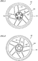
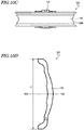
- FIGS. 10A, 10B , 10C, and 10D The workpiece 100' after the flow forming process is shown in FIGS. 10A, 10B , 10C, and 10D .
- FIG. 10A and FIG. 10B are a left side view and a right side view, respectively, schematically showing the workpiece 100' after the flow forming process.
- FIG. 10C is a plan view showing the workpiece 100' after the flow forming process as viewed from a radial direction.
- FIG. 10D is a cross-sectional view taken along line 10D-10D' in FIG. 10A .
- the flow forming process has caused plastic deformation of the precursory rim 120'; more specifically, the precursory rim 120' has been stretched along the axial direction while being also thinned.
- a heat treatment is performed. More specifically, a solution treatment (Step s3), a quenching process (Step s4), and an artificial aging process (Step s5) are performed in this order. This series of processes may sometimes be called a T6 heat treatment.
- the solution treatment may be performed at 530°C for 4.5 hours, for example.
- the quenching process may be performed through water-cooling at 60°C, for example.
- the artificial aging process may be performed at 170°C for 3.2 hours, for example.
- FIG. 11 shows a cross section taken along line 11A-11A' in FIG. 1 .
- a ratio of the wall thickness t1 (see FIG. 10D ) of the precursory rim 120' after Step s2 and before Step s6 to the wall thickness t2 (see FIG. 11 ) of the rim 120 after Step s6 (hereinafter denoted as the "wall thickness ratio t1/t2") is set within a predetermined range.
- the "wall thickness ratio” refers to the ratio of wall thicknesses taken at the same place (or site). Note that the wheel-shaft insertion hole 111 does not need to be formed via a cutting process. For example, at step S1, a workpiece 100' that already has a wheel-shaft insertion hole 111 may be provided.
- Step s1 of forming an intermediate product from an aluminum alloy by a gravity casting technique Step s2 of performing a flow forming process for a precursory rim of the intermediate product is performed.
- Step s2 of performing a flow forming process for a precursory rim of the intermediate product is performed.
- mechanical properties of the rim 120 can be adequately improved.
- the wall thickness ratio t1/t2 is set within a predetermined range. Specifically, the percentage wall thickness ratio t1/t2 is not less than 132% and not more than 433%. As a result, while suitably realizing a desired product shape, the efficiency of material use can be enhanced. Hereinafter, this point will be described in detail.
- the wall thickness ratio t1/t2 preferably satisfies the relationship 1+3/t2max ⁇ t1/t2 ⁇ 1+5/t2min.
- the wall thickness ratio t1/t2 is preferably not less than 132% and not more than 433%, as is calculated from the above equation.
- the efficiency of material use can be enhanced.
- Step s2 is preferably performed in such a manner that, in at least a portion of the precursory rim 120', a ratio of the wall thickness t1 of the precursory rim 120' after Step s2 and before Step s6 to the wall thickness t0 of the precursory rim before Step s2 (see FIG. 8 ) is 50% or less.
- Step s3 of performing a solution treatment after the flow forming process of Step s2, Step s4 of performing a quenching process after Step s3, and Step s5 of performing an artificial aging process after Step s4 may further be included.
- This series of heat treatment processes allows the mechanical properties of the wheel 100 made of an aluminum alloy to be adjusted (e.g., so that it increases in tensile strength, proof stress, and hardness).
- the flow forming apparatus 10 may further include a knockout ring 24 located at an outer periphery of the first mandrel 21.
- the knockout ring 24 is able to move up and down.
- the knockout ring 24 allows the workpiece 100' after the flow forming process to be released from the first mandrel 21.
- an end face (upper surface) of the knockout ring 24 is essentially flush with this reference plane p in the example shown in FIG. 12A ; however, the position of the end face of the knockout ring 24 is not limited thereto.
- the end face of the knockout ring 24 may be offset from the reference plane p along the first direction D1. This will restrain the precursory rim 120' from abutting with the end face of the knockout ring 24 during the flow forming process, thus making it easier for the precursory rim 120' to undergo sufficient plastic deformation.
- an amount of offset a of the knockout ring 24 from the reference plane p is preferably set in accordance with a ratio L1/L2 of a length L1 of the precursory rim 120' after Step s2 and before Step s6 as taken along the axial direction (see FIG. 10D ) to a length L2 of the rim 120 after Step s6 as taken along the axial direction (see FIG. 11 ).
- the amount of offset a increases as the ratio L1/L2 increases.
- the ratio L1/L2 is set to not less than 101% and not more than 113%.
- an intermediate product made of an aluminum alloy is provided.
- the workpiece may suitably be formed by a gravity casting technique, for example.
- Specific shapes for the workpiece are shown in FIG. 13 to FIG. 16 .
- FIG. 13 and FIG. 14 are a left side view and a right side view, respectively, schematically showing the workpiece 100'.
- FIG. 15 and FIG. 16 are cross-sectional views taken along line 15A-15A' and line 16A-16A', respectively, in FIG. 13 .
- the workpiece 100' includes a precursory hub 110', a precursory rim 120', and a plurality of precursory spokes 130' connecting the precursory hub 110' and the precursory rim 120'.
- the precursory hub 110' is a portion to become the hub 110 of the wheel 100.
- the precursory rim 120' is a portion to become the rim 120
- the precursory spokes 130' are portions to become the spokes 130.
- the precursory hub 110' is located at the center of the workpiece 100'. In the example shown, the wheel-shaft insertion hole 111 is not formed in the precursory hub 110' yet.
- the precursory rim 120' has an annular shape, and extends along the circumferential direction of the workpiece 100'.
- the precursory rim 120' has an inner peripheral surface 120a' and an outer peripheral surface 120b'.
- the plurality of precursory spokes 130' connect the precursory hub 110' and the precursory rim 120'. More specifically, the plurality of precursory spokes 130' connect an outer periphery of the precursory hub 110' and the inner peripheral surface 120a' of the precursory rim 120'.
- a flow forming process is performed for the precursory rim 120' of the workpiece 100' by using a flow forming apparatus.
- the flow forming apparatus illustrated in FIG. 9 can be used.
- the inner peripheral surface 120a' of the precursory rim 120' of the workpiece 100' includes: a first region R1 to abut with a first abutting surface 21a of the lower mandrel 21; and a second region R2 to abut with a second abutting surface 22a of the upper mandrel 22.
- each of the first region R1 and the second region R2 includes at least one stepped portion (protrusion) 121 protruding inwardly along the radial direction of the workpiece 100'.
- each of the first region R1 and the second region R2 includes a plurality of (i.e., two or more) stepped portions 121 that are formed discretely along the circumferential direction of the workpiece 100'.
- the stepped portions 121 in the first region R1 and the stepped portions 121 in the second region R2 overlap one another when viewed along the axial direction; however, the positioning of the stepped portions 121 is not limited thereto.
- the stepped portions 121 in the first region R1 and the stepped portions 121 in the second region R2 may be shifted from one another when viewed along the axial direction (i.e., so that the stepped portions 121 in the first region R1 and the stepped portions 121 in the second region R2 are staggered along the circumferential direction).
- the positioning of the first region R1 and the second region R2 is not limited thereto.
- only a portion of a half of the inner peripheral surface 120a' along the axial direction i.e., a lower half in FIG. 15 and FIG. 16
- only a portion of another half of the inner peripheral surface 120a' along the axial direction i.e., an upper half in FIG. 15 and FIG. 16
- FIG. 17 and FIG. 18 show specific examples of the lower mandrel 21 and the upper mandrel 22.
- FIG. 17 is a side view schematically showing the lower mandrel 21 and the upper mandrel 22, illustrating a state where the lower mandrel 21 and the upper mandrel 22 are coupled (more specifically, a guide pin 25 of the lower mandrel 21 is inserted in an aperture of the upper mandrel 22).
- FIG. 18 is a cross-sectional view schematically showing a state where the workpiece 100' is clamped by the lower mandrel 21 and the upper mandrel 22.
- the lower mandrel 21 has the first abutting surface 21a, which abuts with the inner peripheral surface 120a' of the precursory rim 120' from below; and the upper mandrel 22 has the second abutting surface 22a, which abuts with the inner peripheral surface 120a' of the precursory rim 120' from above.
- Each of the first abutting surface 21a of the lower mandrel 21 and the second abutting surface 22a of the upper mandrel 22 is shaped so as to correspond to the plurality of stepped portions 121 of the workpiece 100'.
- each of the first abutting surface 21a of the lower mandrel 21 and the second abutting surface 22a of the upper mandrel 22 includes a plurality of engaging portions (recesses) 23 to engage with the plurality of stepped portions 121.
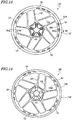
- FIG. 19 and FIG. 20 are a left side view and a right side view, respectively, schematically showing the workpiece 100' after the flow forming process.
- the flow forming process has caused plastic deformation of the precursory rim 120'; more specifically, the precursory rim 120' has been stretched along the axial direction while being also thinned.
- a heat treatment is performed. More specifically, a solution treatment, a quenching process, and an artificial aging process are performed in this order (T6 heat treatment).
- a cutting process is performed. Through the cutting process, the wheel-shaft insertion hole 111 and the like are formed, and also their dimensions are adjusted. At this point, the plurality of stepped portions 121 on the inner peripheral surface 120a' of the precursory rim 120' are removed. In this manner, the wheel 100 is obtained. Note that the wheel-shaft insertion hole 111 does not need to be formed via a cutting process. For example, at the step of providing the workpiece 100', a workpiece 100' that already has a wheel-shaft insertion hole 111 may be provided.
- each of the region (first region) R1 to abut with the lower mandrel (first mandrel) 21 and the region (second region) R2 to abut with the upper mandrel (second mandrel) 22 includes at least one stepped portion 121 protruding inwardly along the radial direction of the workpiece 100'. Because of such a stepped portion(s) 121 being provided on the inner peripheral surface 120a' of the precursory rim 120', the torque from the lower mandrel 21 and the upper mandrel 22 being rotated by the rotating mechanism 31 can be sufficiently transmitted to the workpiece 100'.
- the stepped portion(s) 121 enables clamping of the workpiece 100'. Since this makes it unnecessary to rely on the precursory hub 110' or the precursory spoke 130' for the clamping of the workpiece 100', it becomes possible to produce the wheel 100 in such a manner that clamp scars will not be left on the hub 110 and the spoke 130. For example, since the at least one stepped portion 121 including a clamping surface is removed at the step of performing a cutting process, no clamp scars will be left on the final product (i.e., the wheel 100 for straddled vehicles).
- each of the first region R1 and the second region R2 is not limited to what is illustrated in FIG. 13 and FIG. 14 . It suffices if at least one stepped portion 121 is provided in each of the first region R1 and the second region R2.
- FIG. 21 and FIG. 22 Another exemplary configuration of the stepped portion 121 is shown in FIG. 21 and FIG. 22 .
- only one stepped portion 121 is provided in each of the first region R1 and the second region R2.
- Such a configuration also allows the wheel 100 to be produced without leaving clamp scars on the hub 110 and the spoke 130.
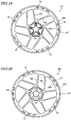
- FIG. 23, FIG. 24 , FIG. 25 and FIG. 26 Still another exemplary configuration of the stepped portion 121 is shown in FIG. 23, FIG. 24 , FIG. 25 and FIG. 26 .
- one stepped portion 121 is formed along the entire circumference along the circumferential direction of the workpiece 100'.
- an upper surface (i.e., a surface of the workpiece 100' facing outward along the axial direction) 121u of the stepped portion 121 has an annular shape, this upper surface 121u functioning as a clamping surface.
- clamping of the workpiece 100' is achieved by utilizing a frictional force occurring between the upper surface (clamping surface) 121u of the stepped portion 121 and the abutting surface (i.e., the first abutting surface 21a of the lower mandrel 21 or the second abutting surface 22a of the upper mandrel 22) of each mandrel pressed against the upper surface 121u.
- a stepped portion 121 (a stepped portion 121 being formed along the entire circumference along the circumferential direction of the workpiece 100') are provided in each of the first region R1 and the second region R2 of the inner peripheral surface 120a' of the precursory rim 120', there is an advantage in that the workpiece 100' can be easily set to the flow forming apparatus 10.
- the workpiece 100' can be prevented from slipping against each mandrel. Moreover, a smaller amount of metal material is needed to form the workpiece 100' than in the case where one stepped portion 121 is formed continuously along the entire circumference.
- Each of the first abutting surface 21a of the lower mandrel 21 and the second abutting surface 22a of the upper mandrel 22 is preferably shaped so as to correspond to at least one stepped portion 121 of the workpiece 100'.
- each of the first abutting surface 21a of the lower mandrel 21 and the second abutting surface 22a of the upper mandrel 22 preferably includes at least one engaging portion 23 to engage with at least one stepped portion 121.
- the workpiece 100' can be formed from a metal material by a gravity casting technique.
- Employing a gravity casting technique provides an advantage of reducing the weight of relatively large wheels because it is easy to form a hollow structure by utilizing a core.
- the aluminum alloy contains silicon (Si) in an amount of not less than 5.0 mass% and not more than 7.5 mass%, magnesium (Mg) in an amount of not less than 0.40 mass% and not more than 0.90 mass%, and aluminum (Al) and inevitable impurities as a balance.
- Non-Patent Document 1 states that, for example, given a constant pour point, lowest fluidity results when the percentage content of Si is 2 to 3 mass%. On the other hand, if the percentage content of Si is too high, toughness may lower. When the percentage content of Si is 7.5 mass% or less, a decrease in toughness can be suppressed.
- Mg yields a deposition (Mg2Si) with Si
- Mg2Si a deposition
- tensile strength and proof stress can be improved.
- the percentage content of Mg is too high, elongation may lower.
- the percentage content of Mg is 0.90 mass% or less, a decrease in elongation due to Mg can be kept at an insignificant level.
- an aluminum alloy having the aforementioned composition has good castability, as well as good tensile strength and proof stress.
- Good castability makes it easier to realize a complicated shape (e.g., the shape of a vehicle wheel) or a thin-walled shape, even by using a gravity casting technique.
- Goode tensile strength and proof stress make it possible to provide a sufficient strength even in the case of a complicated shape or a thin-walled shape.
- an aluminum alloy having the aforementioned composition can be suitably used for vehicle wheels that are produced through a combination of a gravity casting technique and a flow forming process.
- the percentage content of Cu is preferably 0.20 mass% or less.
- the percentage content of Fe is preferably 0.20 mass% or less. If the percentage content of Fe is too high, toughness may lower. When the percentage content of Fe is 0.20 mass% or less, a decrease in toughness that is ascribable to Fe can be suppressed. From the standpoint of suppressing a decrease in toughness, it is more preferable that the percentage content of Fe is 0.15 mass% or less.
- the percentage content of Ti is preferably 0.20 mass% or less. If the percentage content of Ti is too high, a decrease in toughness may be caused. When the percentage content of Ti is 0.20 mass% or less, a decrease in toughness that is ascribable to Ti can be suppressed.
- the aluminum alloy further contains Na in an amount of not less than 0.002 mass% and not more than 0.01 mass%, or Sr in an amount of not less than 0.005 mass% and not more than 0.03 mass%, modification (microstructuring of the eutectic Si phase) can be suitably achieved.
- Table 1 shows the compositions and measurement results of tensile strength, proof stress, and elongation for aluminum alloys of Examples 1 to 3 and Reference Examples 1 to 3.
- elongation the case where a flow forming process was not performed for the sample (indicated as "w/o FF") and the case where a flow forming process was performed for the sample (indicated as "w/ FF") are also shown.
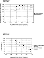
- Examples 1 to 3 and Reference Example 3 their relationship between the percentage content of Si and tensile strength and proof stress is shown in FIG. 27
- their relationship between the percentage content of Si and elongation is shown in FIG. 28 .
- a preferable tensile strength of 300 MPa or more and a preferable proof stress of 250 MPa or more are assumed, and a preferable elongation (in the case of not performing a flow forming process) of 3% or more and a preferable elongation (in the case of performing a flow forming process) of 5% or more are assumed.
- Table 2 shows the compositions and measurement results of tensile strength, proof stress, and elongation for aluminum alloys of Examples 3 to 7 and Reference Examples 4 and 5. Also, for Examples 3 to 7 and Reference Examples 4 and 5, their relationship between the percentage content of Mg and tensile strength and proof stress is shown in FIG. 29 , and their relationship between the percentage content of Mg and elongation is shown in FIG. 30 .
- Table 3 shows the compositions and measurement results of tensile strength, proof stress, and elongation for aluminum alloys of Examples 3, 8 and 9. Also, for Examples 3, 8 and 9, their relationship between the percentage content of Cu and tensile strength and proof stress is shown in FIG. 31 , and their relationship between the percentage content of Cu and elongation is shown in FIG. 32 .
- Example 8 0.20 7.0 0.70 0.11 0.10 0.000 0.012 balance 331 285 3.2 5.4
- Example 9 0.25 7.0 0.71 0.11 0.11 0.000 0.015 balance 333 290 2.5 3.9
- Example 3 and FIG. 31 and FIG. 32 As can be seen from Table 3 and FIG. 31 and FIG. 32 , in Examples 3 and 8, preferable levels are attained in all of tensile strength, proof stress, and elongation. On the other hand, in Example 9, where the percentage content of Cu is 0.25 mass% (i.e., above 0.20 mass%), elongation is smaller than in Examples 3 and 8, as can be seen from Table 3 and FIG. 32 .
- Table 4 shows the compositions and measurement results of tensile strength, proof stress, and elongation for aluminum alloys of Examples 3, 10 and 11. Also, for Examples 3, 10 and 11, their relationship between the percentage content of Fe and tensile strength and proof stress is shown in FIG. 33 , and their relationship between the percentage content of Fe and elongation is shown in FIG. 34 .
- Example 10 0.00 7.3 0.70 0.20 0.11 0.000 0.014 balance 325 285 3.1 5.0
- Example 11 0.00 7.2 0.70 0.24 0.11 0.000 0.012 balance 328 286 1.5 3.0
- Example 3 As can be seen from Table 4 and FIG. 33 and FIG. 34 , in Examples 3 and 10, preferable levels are attained in all of tensile strength, proof stress, and elongation. On the other hand, in Example 11, where the percentage content of Fe is 0.24 mass% (i.e., above 0.20 mass%), elongation is smaller (i.e., toughness is lower) than in Examples 3 and 10, as can be seen from Table 4 and FIG. 34 .
- Table 5 shows the compositions and measurement results of tensile strength, proof stress, and elongation for aluminum alloys of Examples 3, 12 and 13. Also, for Examples 3, 12 and 13, their relationship between the percentage content of Ti and tensile strength and proof stress is shown in FIG. 35 , and their relationship between the percentage content of Ti and elongation is shown in FIG. 36 .
- Example 3 As can be seen from Table 5 and FIG. 35 and FIG. 36 , in Examples 3 and 12, preferable levels are attained in all of tensile strength, proof stress, and elongation. On the other hand, in Example 13, where the percentage content of Ti is 0.24 mass% (i.e., above 0.20 mass%), elongation is smaller (i.e., toughness is lower) than in Examples 3 and 10, as can be seen from Table 5 and FIG. 36 .
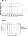
- Table 6 shows the compositions and measurement results of tensile strength, proof stress, and elongation for aluminum alloys of Examples 3, and 14 to 20. Also, for Examples 14 to 17, their relationship between the percentage content of Na and tensile strength and proof stress is shown in FIG. 37 , and their relationship between the percentage content of Na and elongation is shown in FIG. 38 . Also, for Examples 3, 14, and 18 to 20, their relationship between the percentage content of Sr and tensile strength and proof stress is shown in FIG. 39 , and their relationship between the percentage content of Sr and elongation is shown in FIG. 40 .
- Example 3 As can be seen from Table 6 and FIG. 37 to FIG. 40 , in Examples 3, and 15 to 20, preferable levels are attained in all of tensile strength, proof stress, and elongation. On the other hand, in Example 14, where neither Na nor Sr is substantially contained, elongation is smaller than in Examples 3, and 15 to 20, as can be seen from Table 6 and FIG. 38 and FIG. 40 . This is presumably because modification (microstructuring of the eutectic Si phase) is not suitably achieved.
- a method of producing a wheel for straddled vehicles that is able to adequately improve the mechanical properties of a rim.
- a production method according to an embodiment of the present teaching can be suitably used for the production of a wheel for various straddled vehicles, such as motorcycles.
Landscapes
- Engineering & Computer Science (AREA)
- Mechanical Engineering (AREA)
- Forging (AREA)
Abstract
Description
- The present invention relates to a method of producing a wheel for straddled vehicles.
- In recent years, along with steels, aluminum alloys are widely used as the material of wheels for automotive vehicles.
-
JP 5205655 B2 - However, when producing a wheel made of an aluminum alloy by using a gravity casting technique, some improvement could still be made in the material strength (mechanical properties) of the rim, in which solidification tends to be slow and defects are likely to remain.
- The present invention has been made in view of the above problem, and an objective thereof is to provide a method of producing a wheel for straddled vehicles that is able to adequately improve the mechanical properties of a rim. According to the present invention said object is solved by a method of producing a wheel for straddled vehicles having the features of
independent claim 1. Preferred embodiments are laid down in the dependent claims. - The present specification discloses a method of producing a wheel for straddled vehicles as recited in the following Items.
- A method of producing a wheel for straddled vehicles, the wheel including: a hub having an aperture into which a wheel shaft is to be inserted; an annular rim; and a plurality of spokes connecting the hub and the rim, the method comprising:
- step (A) of forming an intermediate product from an aluminum alloy by using a gravity casting technique, the intermediate product including a precursory hub, an annular precursory rim, and a plurality of precursory spokes connecting the precursory hub and the precursory rim;
- step (B) of performing a flow forming process for the precursory rim of the intermediate product by using a flow forming apparatus, wherein, while the intermediate product is rotated, at least a portion of the precursory rim is drawn in a first direction and a second direction, the first direction being one direction that extends from a center of the intermediate product on an axial direction thereof, and the second direction being an opposite direction that extends from the center of the intermediate product on the axial direction; and
- step (C) of, after step (B), performing a cutting process for the intermediate product to at least complete the rim, wherein,
- In the production method according to
Item 1, after step (A) of forming an intermediate product from an aluminum alloy by a gravity casting technique, step (B) of performing a flow forming process for a precursory rim of the intermediate product is performed. As a result of this, mechanical properties (e.g., elongation) of the rim can be adequately improved. Moreover, a ratio of a wall thickness of the precursory rim after step (B) and before step (C) to a wall thickness of the rim after step (C) is not less than 132% and not more than 433%. As a result, while suitably realizing a desired product shape, the efficiency of material use can be enhanced. - The production method of
Item 1, wherein step (B) is performed in such a manner that, in at least a portion of the precursory rim, a ratio of the wall thickness of the precursory rim after step (B) and before step (C) to a wall thickness of the precursory rim before step (B) is 50% or less. - From the standpoint of adequately improving the mechanical properties of the rim through the flow forming process, step (B) is preferably performed in such a manner that, in at least a portion of the precursory rim, a ratio of the wall thickness of the precursory rim after step (B) and before step (C) to the wall thickness of the precursory rim before step (B) is 50% or less.
- [Item 3]
- The production method of
Item
the flow forming apparatus includes:
a first mandrel having a first abutting surface that abuts with an inner peripheral surface of the precursory rim of the intermediate product from one direction along the axial direction;
a second mandrel having a second abutting surface that abuts with the inner peripheral surface of the precursory rim of the intermediate product from an opposite direction along the axial direction;
a rotating mechanism to rotate the first mandrel and the second mandrel; and
a roller to be pressed against an outer peripheral surface of the precursory rim of the intermediate product. - The production method of Item 3, wherein,
the flow forming apparatus further includes a knockout ring located near an outer periphery of the first mandrel so as to be able to move up and down;
an upper surface of the knockout ring is offset from a reference plane along the first direction; and
an amount of offset of an upper surface of the knockout ring from the reference plane is set so that the amount increases as a ratio L1/L2 increases, wherein the ratio L1/L2 is a ratio of a length L1 of the precursory rim after step (B) and before step (C) as taken along the axial direction to a length L2 of the rim after step (C) as taken along the axial direction. - The upper surface of the knockout ring may be offset from the reference plane along the first direction. This will restrain the precursory rim from abutting with the upper surface of the knockout ring during the flow forming process, thus making it easier for the precursory rim to undergo sufficient plastic deformation. Herein, an amount of offset of the knockout ring from the reference plane is preferably set in accordance with a ratio L1/L2 of a length L1 of the precursory rim after step (B) and before step (C) as taken along the axial direction to a length L2 of the rim after step (C) as taken along the axial direction. Specifically, it is preferable that the amount of offset increases as the ratio L1/L2 increases.
- The production method of Item 4, wherein the ratio L1/L2 is not less than 101% and not more than 113%.
- The ratio L1/L2 is preferably set to not less than 101% and not more than 113%.
- The production method of any of Items 3 to 5, wherein,
the inner peripheral surface of the precursory rim of the intermediate product formed at step (A) includes a first region to abut with the first abutting surface of the first mandrel and a second region to abut with the second abutting surface of the second mandrel; and
each of the first region and the second region of the inner peripheral surface of the precursory rim includes at least one stepped portion protruding inwardly along a radial direction of the intermediate product. - Within the inner peripheral surface of the precursory rim of the intermediate product (workpiece) provided, each of the region (first region) to abut with the first mandrel and the region (second region) to abut with the second mandrel may include at least one stepped portion protruding inwardly along the radial direction of the intermediate product. As a result, the torque from the first mandrel and the second mandrel being rotated by the rotating mechanism can be sufficiently transmitted to the intermediate product. In other words, the stepped portion(s) enables clamping of the intermediate product. Since this makes it unnecessary to rely on the precursory hub or the precursory spoke for the clamping of the intermediate product, it becomes possible to produce the wheel for straddled vehicles in such a manner that clamp scars will not be left on the hub and the spoke.
- The production method of
Item 6, wherein the at least one stepped portion is one stepped portion formed along an entire circumference along a circumferential direction of the intermediate product. - The at least one stepped portion may be one stepped portion that is formed along the entire circumference along the circumferential direction of the intermediate product. In that case, an upper surface (i.e., a surface of the intermediate product outward along the axial direction) of the stepped portion has an annular shape, this upper surface functioning as a clamping surface. Specifically, clamping of the intermediate product is achieved by utilizing a frictional force occurring between the upper surface (clamping surface) of the stepped portion and the abutting surface (i.e., the first abutting surface of the first mandrel or the second abutting surface of the second mandrel) of each mandrel pressed against the upper surface.
- In the case where such a stepped portion (a stepped portion being formed along the entire circumference along the circumferential direction of the intermediate product) are provided in each of the first region and the second region of the inner peripheral surface of the precursory rim, there is an advantage in that the intermediate product can be easily set to the flow forming apparatus.
- The production method of
Item 6, wherein the at least one stepped portion comprises a plurality of stepped portions that are formed discretely along a circumferential direction of the intermediate product. - The at least one stepped portion may be a plurality of stepped portions that are formed discretely along the circumferential direction of the intermediate product. In that case, the torque from the mandrel (the first mandrel or the second mandrel) can be received on a partial side surface (a side surface oriented in the circumferential direction of the intermediate product) of each stepped portion, so that not only the upper surface of each stepped portion but also the partial side surface functions as a clamping surface.
- In the case where such a plurality of stepped portions are provided on the inner peripheral surface of the precursory rim, the intermediate product can be prevented from slipping against each mandrel. Moreover, a smaller amount of metal material is needed to form the intermediate product than in the case where one stepped portion is formed continuously along the entire circumference.
- The production method of any of
Items 6 to 8, wherein each of the first abutting surface of the first mandrel and the second abutting surface of the second mandrel includes at least one engaging portion to engage with the at least one stepped portion. - Each of the first abutting surface of the first mandrel and the second abutting surface of the second mandrel is preferably shaped so as to correspond to at least one stepped portion of the intermediate product. Specifically, each of the first abutting surface of the first mandrel and the second abutting surface of the second mandrel preferably includes at least one engaging portion to engage with at least one stepped portion.
- The production method of any of
Items 6 to 9, wherein the at least one stepped portion is removed in step (C). - Because the at least one stepped portion including a clamping surface is removed at step (C), no clamp scars will be left on the final product (i.e., the wheel for straddled vehicles).
- According to an embodiment of the present teaching, there is provided a method of producing a wheel for straddled vehicles that is able to adequately improve the mechanical properties of a rim.
-
-
FIG. 1 is a left side view schematically showing awheel 100 for straddled vehicles. -
FIG. 2 is a right side view schematically showing thewheel 100. -
FIG. 3 is a plan view showing thewheel 100 as viewed from a radial direction. -
FIG. 4 is a flowchart showing an example of a method of producing thewheel 100. -
FIG. 5 is a left side view schematically showing an intermediate product (workpiece) 100'. -
FIG. 6 is a right side view schematically showing the workpiece 100'. -
FIG. 7 is a plan view showing the workpiece 100' as viewed from a radial direction. -
FIG. 8 is a cross-sectional view taken alongline 8A-8A' inFIG. 5 . -
FIG. 9 is a diagram schematically showing aflow forming apparatus 10. -
FIG. 10A is a left side view schematically showing the workpiece 100' after a flow forming process. -
FIG. 10B is a right side view schematically showing the workpiece 100' after a flow forming process. -
FIG. 10C is a plan view showing the workpiece 100' after a flow forming process as viewed from a radial direction. -
FIG. 10D is a cross-sectional view taken alongline 10D-10D' inFIG. 10A . -
FIG. 11 is a cross-sectional view taken alongline 11A-11A' inFIG. 1 . -
FIG. 12A is a diagram showing an example positioning of aknockout ring 24. -
FIG. 12B is a diagram showing another example positioning of theknockout ring 24. -
FIG. 13 is a left side view schematically showing the workpiece 100'. -
FIG. 14 is a right side view schematically showing the workpiece 100'. -
FIG. 15 is a cross-sectional view taken alongline 15A-15A' inFIG. 13 . -
FIG. 16 is a cross-sectional view taken alongline 16A-16A' inFIG. 13 . -
FIG. 17 is a side view schematically showing alower mandrel 21 and anupper mandrel 22. -
FIG. 18 is a cross-sectional view schematically showing a state where the workpiece 100' is clamped by thelower mandrel 21 and theupper mandrel 22. -
FIG. 19 is a left side view schematically showing the workpiece 100' after a flow forming process. -
FIG. 20 is a right side view schematically showing the workpiece 100' after a flow forming process. -
FIG. 21 is a left side view schematically showing the workpiece 100'. -
FIG. 22 is a right side view schematically showing the workpiece 100'. -
FIG. 23 is a left side view schematically showing the workpiece 100'. -
FIG. 24 is a right side view schematically showing the workpiece 100'. -
FIG. 25 is a cross-sectional view taken alongline 25A-25A' inFIG. 23 . -
FIG. 26 is a cross-sectional view taken alongline 26A-26A' inFIG. 23 . -
FIG. 27 is a graph showing a relationship between the percentage content of Si and tensile strength and proof stress for Examples 1 to 3 and Reference Example 3. -
FIG. 28 is a graph showing a relationship between the percentage content of Si and elongation for Examples 1 to 3 and Reference Example 3. -
FIG. 29 is a graph showing a relationship between the percentage content of Mg and tensile strength and proof stress for Examples 3 to 7 and Reference Examples 4 and 5. -
FIG. 30 is a graph showing a relationship between the percentage content of Mg and elongation for Examples 3 to 7 and Reference Examples 4 and 5. -
FIG. 31 is a graph showing a relationship between the percentage content of Cu and tensile strength and proof stress for Examples 3, 8 and 9. -
FIG. 32 is a graph showing a relationship between the percentage content of Cu and elongation for Examples 3, 8 and 9. -
FIG. 33 is a graph showing a relationship between the percentage content of Fe and tensile strength and proof stress for Examples 3, 10 and 11. -
FIG. 34 is a graph showing a relationship between the percentage content of Fe and elongation for Examples 3, 10 and 11. -
FIG. 35 is a graph showing a relationship between the percentage content of Ti and tensile strength and proof stress for Examples 3, 12 and 13. -
FIG. 36 is a graph showing a relationship between the percentage content of Ti and elongation for Examples 3, 12 and 13. -
FIG. 37 is a graph showing a relationship between the percentage content of Na and tensile strength and proof stress for Examples 14 to 17. -
FIG. 38 is a graph showing a relationship between the percentage content of Na and elongation for Examples 14 to 17. -
FIG. 39 is a graph showing a relationship between the percentage content of Sr and tensile strength and proof stress for Examples 3, 14, and 18 to 20. -
FIG. 40 is a graph showing a relationship between the percentage content of Sr and elongation for Examples 3, 14, and 18 to 20. - Hereinafter, embodiments of the present teaching will be described with reference to the drawings.
- With reference to
FIGS. 1 to 3 , an example of a wheel for straddled vehicles (hereinafter simply referred to as a "wheel") that is produced by a production method according to an embodiment of the present teaching will be described.FIGS. 1 and 2 are a left side view and a right side view, respectively, schematically showing thewheel 100.FIG. 3 is a plan view showing thewheel 100 from a radial direction. - As shown in
FIGS. 1, 2 and3 , thewheel 100 includes ahub 110, arim 120, and a plurality ofspokes 130. Thewheel 100 is made of a metal material. Thehub 110, therim 120, and the plurality ofspokes 130 are monolithically formed. - The
hub 110 is located in the center of thewheel 100, and has an aperture (wheel-shaft insertion hole) 111, into which a wheel shaft is to be inserted. A direction that is parallel to a center axis of the wheel-shaft insertion hole 111 may be referred to as the "axial direction" hereinbelow. Note that the specific shape of thehub 110 is not limited to what is illustrated inFIG. 1 , etc. - The
rim 120 has an annular shape, and extends along the circumferential direction of thewheel 100. Therim 120 has an innerperipheral surface 120a and an outerperipheral surface 120b. A tire is to be mounted on the outerperipheral surface 120b of therim 120. - The plurality of
spokes 130 connect thehub 110 and therim 120. More specifically, the plurality ofspokes 130 connect an outer periphery of thehub 110 and the innerperipheral surface 120a of therim 120. Although the example shown illustrates thewheel 100 as having tenspokes 130, the number ofspokes 130 is not limited to ten. Although the example shown illustrates that twoadjacent spokes 130 are united at thehub 110 side, the configuration of thespokes 130 is not limited thereto. - With reference to
FIG. 4 , a method of producing thewheel 100 will be described.FIG. 4 is a flowchart showing an example of a method of producing thewheel 100. - First, by using a gravity casting technique, an intermediate product (hereinafter referred to as a "workpiece") 100' is formed from an aluminum alloy (Step s1). Specific shapes for the workpiece 100' are shown in
FIG. 5 to FIG. 8 .FIG. 5 and FIG. 6 are a left side view and a right side view, respectively, schematically showing the workpiece 100'.FIG. 7 is a plan view showing the workpiece 100' as viewed from a radial direction.FIG. 8 is a cross-sectional view taken alongline 8A-8A' inFIG. 5 . - As shown in
FIG. 5 to FIG. 7 , the workpiece 100' includes a precursory hub 110', a precursory rim 120', and a plurality ofprecursory spokes 130' connecting the precursory hub 110' and the precursory rim 120'. The precursory hub 110' is a portion to become thehub 110 of thewheel 100. Similarly, the precursory rim 120' is a portion to become therim 120, and theprecursory spokes 130' are portions to become thespokes 130. - The precursory hub 110' is located at the center of the workpiece 100'. In the example shown, the wheel-
shaft insertion hole 111 is not formed in the precursory hub 110' yet. The precursory rim 120' has an annular shape, and extends along the circumferential direction of the workpiece 100'. The precursory rim 120' has an innerperipheral surface 120a' and an outerperipheral surface 120b'. The plurality ofprecursory spokes 130' connect the precursory hub 110' and the precursory rim 120'. More specifically, the plurality ofprecursory spokes 130' connect an outer periphery of the precursory hub 110' and the innerperipheral surface 120a' of the precursory rim 120'. - Then, a flow forming process is performed for the precursory rim 120' of the workpiece 100' by using a flow forming apparatus (Step s2). In this Step s2, while the workpiece 100' is rotated, at least a portion of the precursory rim 120' is drawn in a first direction D1, which is one direction that extends from the center of the workpiece 100' on its axial direction (see
FIG. 8 ) and in a second direction D2, which is an opposite direction that extends from the center of the workpiece 100' on its axial direction (seeFIG. 8 ). - An example of a flow forming apparatus to be used at Step s2 is shown in
FIG. 9 . Theflow forming apparatus 10 shown inFIG. 9 includes: afirst mandrel 21 and asecond mandrel 22; arotating mechanism 31 to rotate thefirst mandrel 21 and thesecond mandrel 22; and aroller 41 to be pressed against the outerperipheral surface 120b' of the precursory rim 120' of the workpiece 100'. - Hereinafter, between the
first mandrel 21 and thesecond mandrel 22, thefirst mandrel 21 being located relatively low will be referred to as the "lower mandrel", whereas thesecond mandrel 22 being located relatively high will be referred to as the "upper mandrel". - The
rotating mechanism 31, which includes a motor, is placed on a pedestal 11. Thelower mandrel 21 is attached to a leading end of therotating mechanism 31. On aroof 12, amandrel moving mechanism 32 to move theupper mandrel 22 up or down is placed. Theupper mandrel 22 is attached to a leading end of themandrel moving mechanism 32. On awall 13, aroller moving mechanism 33 to move theroller 41 in the up-down direction, the right-left direction, or the front-rear direction is placed. Theroller 41 is supported, in a rotatable manner, by anarm 42 that is attached to a leading end of theroller moving mechanism 33. - With the workpiece 100' being externally fitted on the
lower mandrel 21 and theupper mandrel 22, a flow forming process is performed. At this time, thelower mandrel 21 and theupper mandrel 22 are coupled in such a manner that theupper mandrel 22 will rotate as thelower mandrel 21 rotates. For example, the flow forming process may be performed in a state where a portion thelower mandrel 21 is fitted in a portion of theupper mandrel 22. - The
lower mandrel 21 has a surface (hereinafter referred to as the "first abutting surface") 21a that abuts with the innerperipheral surface 120a' of the precursory rim 120' of the workpiece 100' from one direction (e.g., from below herein) along the axial direction of the workpiece 100'. - The
upper mandrel 22 has a surface (hereinafter referred to as the "second abutting surface") 22a that abuts with the innerperipheral surface 120a' of the precursory rim 120' of the workpiece 100' from the opposite direction (e.g., from above herein) along the axial direction of the workpiece 100'. - When the
lower mandrel 21 and theupper mandrel 22 are rotated by the rotatingmechanism 31, the workpiece 100' rotates accordingly. As theroller 41 is pressed against the outerperipheral surface 120b' of the precursory rim 120' of the workpiece 100' in this state, the flow forming process is accomplished. - The workpiece 100' after the flow forming process is shown in
FIGS. 10A, 10B ,10C, and 10D .FIG. 10A and FIG. 10B are a left side view and a right side view, respectively, schematically showing the workpiece 100' after the flow forming process.FIG. 10C is a plan view showing the workpiece 100' after the flow forming process as viewed from a radial direction.FIG. 10D is a cross-sectional view taken alongline 10D-10D' inFIG. 10A . As shown inFIGS. 10A, 10B ,10C, and 10D , the flow forming process has caused plastic deformation of the precursory rim 120'; more specifically, the precursory rim 120' has been stretched along the axial direction while being also thinned. - Next, a heat treatment is performed. More specifically, a solution treatment (Step s3), a quenching process (Step s4), and an artificial aging process (Step s5) are performed in this order. This series of processes may sometimes be called a T6 heat treatment. The solution treatment may be performed at 530°C for 4.5 hours, for example. The quenching process may be performed through water-cooling at 60°C, for example. The artificial aging process may be performed at 170°C for 3.2 hours, for example.
- Thereafter, a cutting process is performed for the workpiece 100', thereby at least completing the rim 120 (Step s6). Through the cutting process, the wheel-
shaft insertion hole 111 and the like are formed, and also their dimensions are adjusted. In this manner, thewheel 100 is obtained.FIG. 11 shows a cross section taken alongline 11A-11A' inFIG. 1 . In the present embodiment, a ratio of the wall thickness t1 (seeFIG. 10D ) of the precursory rim 120' after Step s2 and before Step s6 to the wall thickness t2 (seeFIG. 11 ) of therim 120 after Step s6 (hereinafter denoted as the "wall thickness ratio t1/t2") is set within a predetermined range. Note that the "wall thickness ratio" refers to the ratio of wall thicknesses taken at the same place (or site). Note that the wheel-shaft insertion hole 111 does not need to be formed via a cutting process. For example, at step S1, a workpiece 100' that already has a wheel-shaft insertion hole 111 may be provided. - As described above, in the method of producing the
wheel 100 according to an embodiment of the present teaching, after Step s1 of forming an intermediate product from an aluminum alloy by a gravity casting technique, Step s2 of performing a flow forming process for a precursory rim of the intermediate product is performed. As a result of this, mechanical properties of therim 120 can be adequately improved. - Moreover, in the method of producing the
wheel 100 according to an embodiment of the present teaching, the wall thickness ratio t1/t2 is set within a predetermined range. Specifically, the percentage wall thickness ratio t1/t2 is not less than 132% and not more than 433%. As a result, while suitably realizing a desired product shape, the efficiency of material use can be enhanced. Hereinafter, this point will be described in detail. - Assuming a cut margin a [mm] in Step s6 (cutting process), the wall thickness t1 is expressed as t1=t2+a, and therefore the wall thickness ratio t1/t2 is expressed as t1/t2=1+a/t2. If the cut margin a is less than 3.0 mm, it may be difficult to realize a desired product shape. On the other hand, if the cut margin exceeds 5.0 mm, the efficiency of use of the material (which herein is an aluminum alloy) is somewhat decreased. Therefore, when one assumes a minimum product wall thickness t2min [mm] and a maximum product wall thickness t2max [mm], it may be said that the wall thickness ratio t1/t2 preferably satisfies the
relationship 1+3/t2max ≤ t1/t2 ≤ 1+5/t2min. Herein, given that the minimum product wall thickness t2min is 1.5 mm and that the maximum product wall thickness t2max is 9.5 mm, the wall thickness ratio t1/t2 is preferably not less than 132% and not more than 433%, as is calculated from the above equation. - Thus, because of the wall thickness ratio t1/t2 being not less than 132% and not more than 433%, while suitably realizing a desired product shape, the efficiency of material use can be enhanced.
- From the standpoint of adequately improving the mechanical properties of the
rim 120 through the flow forming process, Step s2 is preferably performed in such a manner that, in at least a portion of the precursory rim 120', a ratio of the wall thickness t1 of the precursory rim 120' after Step s2 and before Step s6 to the wall thickness t0 of the precursory rim before Step s2 (seeFIG. 8 ) is 50% or less. - Moreover, as in the above-described production method, Step s3 of performing a solution treatment after the flow forming process of Step s2, Step s4 of performing a quenching process after Step s3, and Step s5 of performing an artificial aging process after Step s4 may further be included. This series of heat treatment processes allows the mechanical properties of the
wheel 100 made of an aluminum alloy to be adjusted (e.g., so that it increases in tensile strength, proof stress, and hardness). - As shown in
FIG. 12A , theflow forming apparatus 10 may further include aknockout ring 24 located at an outer periphery of thefirst mandrel 21. Theknockout ring 24 is able to move up and down. Theknockout ring 24 allows the workpiece 100' after the flow forming process to be released from thefirst mandrel 21. - Given a reference plane p, which is an imaginary plane that is defined by one end face of the workpiece 100' after the flow forming process along the axial direction, an end face (upper surface) of the
knockout ring 24 is essentially flush with this reference plane p in the example shown inFIG. 12A ; however, the position of the end face of theknockout ring 24 is not limited thereto. As shown inFIG. 12B , the end face of theknockout ring 24 may be offset from the reference plane p along the first direction D1. This will restrain the precursory rim 120' from abutting with the end face of theknockout ring 24 during the flow forming process, thus making it easier for the precursory rim 120' to undergo sufficient plastic deformation. Herein, an amount of offset a of theknockout ring 24 from the reference plane p is preferably set in accordance with a ratio L1/L2 of a length L1 of the precursory rim 120' after Step s2 and before Step s6 as taken along the axial direction (seeFIG. 10D ) to a length L2 of therim 120 after Step s6 as taken along the axial direction (seeFIG. 11 ). Specifically, it is preferable that the amount of offset a increases as the ratio L1/L2 increases. Preferably, the ratio L1/L2 is set to not less than 101% and not more than 113%. - Another example method of producing the
wheel 100 will be described. - First, an intermediate product (workpiece) made of an aluminum alloy is provided. The workpiece may suitably be formed by a gravity casting technique, for example. Specific shapes for the workpiece are shown in
FIG. 13 to FIG. 16 .FIG. 13 and FIG. 14 are a left side view and a right side view, respectively, schematically showing the workpiece 100'.FIG. 15 and FIG. 16 are cross-sectional views taken alongline 15A-15A' andline 16A-16A', respectively, inFIG. 13 . - As shown in
FIG. 13 to FIG. 16 , the workpiece 100' includes a precursory hub 110', a precursory rim 120', and a plurality ofprecursory spokes 130' connecting the precursory hub 110' and the precursory rim 120'. The precursory hub 110' is a portion to become thehub 110 of thewheel 100. Similarly, the precursory rim 120' is a portion to become therim 120, and theprecursory spokes 130' are portions to become thespokes 130. - The precursory hub 110' is located at the center of the workpiece 100'. In the example shown, the wheel-
shaft insertion hole 111 is not formed in the precursory hub 110' yet. The precursory rim 120' has an annular shape, and extends along the circumferential direction of the workpiece 100'. The precursory rim 120' has an innerperipheral surface 120a' and an outerperipheral surface 120b'. The plurality ofprecursory spokes 130' connect the precursory hub 110' and the precursory rim 120'. More specifically, the plurality ofprecursory spokes 130' connect an outer periphery of the precursory hub 110' and the innerperipheral surface 120a' of the precursory rim 120'. - Then, a flow forming process is performed for the precursory rim 120' of the workpiece 100' by using a flow forming apparatus. At this step, the flow forming apparatus illustrated in
FIG. 9 can be used. - As shown in
FIG. 15 and FIG. 16 , the innerperipheral surface 120a' of the precursory rim 120' of the workpiece 100' includes: a first region R1 to abut with a firstabutting surface 21a of thelower mandrel 21; and a second region R2 to abut with a secondabutting surface 22a of theupper mandrel 22. As shown inFIG. 13, FIG. 14 andFIG. 16 , each of the first region R1 and the second region R2 includes at least one stepped portion (protrusion) 121 protruding inwardly along the radial direction of the workpiece 100'. In the example shown, each of the first region R1 and the second region R2 includes a plurality of (i.e., two or more) steppedportions 121 that are formed discretely along the circumferential direction of the workpiece 100'. - In the configuration illustrated herein, the stepped
portions 121 in the first region R1 and the steppedportions 121 in the second region R2 overlap one another when viewed along the axial direction; however, the positioning of the steppedportions 121 is not limited thereto. Alternatively, the steppedportions 121 in the first region R1 and the steppedportions 121 in the second region R2 may be shifted from one another when viewed along the axial direction (i.e., so that the steppedportions 121 in the first region R1 and the steppedportions 121 in the second region R2 are staggered along the circumferential direction). Although an example has been illustrated where essentially the entire innerperipheral surface 120a' of the precursory rim 120' consists of the first region R1 and the second region R2, the positioning of the first region R1 and the second region R2 is not limited thereto. Alternatively, only a portion of a half of the innerperipheral surface 120a' along the axial direction (i.e., a lower half inFIG. 15 and FIG. 16 ) may be the first region R1, while only a portion of another half of the innerperipheral surface 120a' along the axial direction (i.e., an upper half inFIG. 15 and FIG. 16 ) may be the second region R2. -
FIG. 17 andFIG. 18 show specific examples of thelower mandrel 21 and theupper mandrel 22.FIG. 17 is a side view schematically showing thelower mandrel 21 and theupper mandrel 22, illustrating a state where thelower mandrel 21 and theupper mandrel 22 are coupled (more specifically, aguide pin 25 of thelower mandrel 21 is inserted in an aperture of the upper mandrel 22).FIG. 18 is a cross-sectional view schematically showing a state where the workpiece 100' is clamped by thelower mandrel 21 and theupper mandrel 22. - As has already been described, the
lower mandrel 21 has the firstabutting surface 21a, which abuts with the innerperipheral surface 120a' of the precursory rim 120' from below; and theupper mandrel 22 has the secondabutting surface 22a, which abuts with the innerperipheral surface 120a' of the precursory rim 120' from above. Each of the firstabutting surface 21a of thelower mandrel 21 and the secondabutting surface 22a of theupper mandrel 22 is shaped so as to correspond to the plurality of steppedportions 121 of the workpiece 100'. Specifically, each of the firstabutting surface 21a of thelower mandrel 21 and the secondabutting surface 22a of theupper mandrel 22 includes a plurality of engaging portions (recesses) 23 to engage with the plurality of steppedportions 121. - When the
lower mandrel 21 and theupper mandrel 22 are rotated by the rotatingmechanism 31, the workpiece 100' rotates accordingly. As theroller 41 is pressed against the outerperipheral surface 120b' of the precursory rim 120' of the workpiece 100' in this state, the flow forming process is accomplished. - The workpiece 100' after the flow forming process are shown in
FIG. 19 and FIG. 20. FIG. 19 and FIG. 20 are a left side view and a right side view, respectively, schematically showing the workpiece 100' after the flow forming process. The flow forming process has caused plastic deformation of the precursory rim 120'; more specifically, the precursory rim 120' has been stretched along the axial direction while being also thinned. - Next, a heat treatment is performed. More specifically, a solution treatment, a quenching process, and an artificial aging process are performed in this order (T6 heat treatment).
- Thereafter, a cutting process is performed. Through the cutting process, the wheel-
shaft insertion hole 111 and the like are formed, and also their dimensions are adjusted. At this point, the plurality of steppedportions 121 on the innerperipheral surface 120a' of the precursory rim 120' are removed. In this manner, thewheel 100 is obtained. Note that the wheel-shaft insertion hole 111 does not need to be formed via a cutting process. For example, at the step of providing the workpiece 100', a workpiece 100' that already has a wheel-shaft insertion hole 111 may be provided. - In the example described above, within the inner
peripheral surface 120a' of the precursory rim 120' of the intermediate product (workpiece) 100' provided, each of the region (first region) R1 to abut with the lower mandrel (first mandrel) 21 and the region (second region) R2 to abut with the upper mandrel (second mandrel) 22 includes at least one steppedportion 121 protruding inwardly along the radial direction of the workpiece 100'. Because of such a stepped portion(s) 121 being provided on the innerperipheral surface 120a' of the precursory rim 120', the torque from thelower mandrel 21 and theupper mandrel 22 being rotated by the rotatingmechanism 31 can be sufficiently transmitted to the workpiece 100'. In other words, the stepped portion(s) 121 enables clamping of the workpiece 100'. Since this makes it unnecessary to rely on the precursory hub 110' or the precursory spoke 130' for the clamping of the workpiece 100', it becomes possible to produce thewheel 100 in such a manner that clamp scars will not be left on thehub 110 and thespoke 130. For example, since the at least one steppedportion 121 including a clamping surface is removed at the step of performing a cutting process, no clamp scars will be left on the final product (i.e., thewheel 100 for straddled vehicles). - Note that the number of stepped
portions 121 in each of the first region R1 and the second region R2 is not limited to what is illustrated inFIG. 13 and FIG. 14 . It suffices if at least one steppedportion 121 is provided in each of the first region R1 and the second region R2. - Another exemplary configuration of the stepped
portion 121 is shown inFIG. 21 and FIG. 22 . In the example shown inFIG. 21 and FIG. 22 , only one steppedportion 121 is provided in each of the first region R1 and the second region R2. Such a configuration also allows thewheel 100 to be produced without leaving clamp scars on thehub 110 and thespoke 130. - Still another exemplary configuration of the stepped
portion 121 is shown inFIG. 23, FIG. 24 ,FIG. 25 and FIG. 26 . In the example shown inFIG. 23 to FIG. 26 , in each of the first region R1 and the second region R2, one steppedportion 121 is formed along the entire circumference along the circumferential direction of the workpiece 100'. In this case, an upper surface (i.e., a surface of the workpiece 100' facing outward along the axial direction) 121u of the steppedportion 121 has an annular shape, thisupper surface 121u functioning as a clamping surface. Specifically, clamping of the workpiece 100' is achieved by utilizing a frictional force occurring between the upper surface (clamping surface) 121u of the steppedportion 121 and the abutting surface (i.e., the firstabutting surface 21a of thelower mandrel 21 or the secondabutting surface 22a of the upper mandrel 22) of each mandrel pressed against theupper surface 121u. - In the case where such a stepped portion 121 (a stepped
portion 121 being formed along the entire circumference along the circumferential direction of the workpiece 100') are provided in each of the first region R1 and the second region R2 of the innerperipheral surface 120a' of the precursory rim 120', there is an advantage in that the workpiece 100' can be easily set to theflow forming apparatus 10. - On the other hand, as was illustrated in
FIG. 13 and FIG. 14 , etc., when a plurality of steppedportions 121 are formed discretely along the circumferential direction of the workpiece 100', the torque from the mandrel (thelower mandrel 21 or the upper mandrel 22) can be received on a partial side surface (a side surface oriented in the circumferential direction of the workpiece 100') of each steppedportion 121, so that not only theupper surface 121u of each steppedportion 121 but also the partial side surface functions as a clamping surface. - In the case where a plurality of stepped
portions 121 are provided on the innerperipheral surface 120a' of the precursory rim 120', the workpiece 100' can be prevented from slipping against each mandrel. Moreover, a smaller amount of metal material is needed to form the workpiece 100' than in the case where one steppedportion 121 is formed continuously along the entire circumference. - Each of the first
abutting surface 21a of thelower mandrel 21 and the secondabutting surface 22a of theupper mandrel 22 is preferably shaped so as to correspond to at least one steppedportion 121 of the workpiece 100'. Specifically, as is illustrated, each of the firstabutting surface 21a of thelower mandrel 21 and the secondabutting surface 22a of theupper mandrel 22 preferably includes at least one engagingportion 23 to engage with at least one steppedportion 121. - In the step of providing the workpiece 100', the workpiece 100' can be formed from a metal material by a gravity casting technique. Employing a gravity casting technique provides an advantage of reducing the weight of relatively large wheels because it is easy to form a hollow structure by utilizing a core.
- Preferable compositions for the aluminum alloy to be used as the material of the
wheel 100 will be described. - Preferably, the aluminum alloy contains silicon (Si) in an amount of not less than 5.0 mass% and not more than 7.5 mass%, magnesium (Mg) in an amount of not less than 0.40 mass% and not more than 0.90 mass%, and aluminum (Al) and inevitable impurities as a balance.
- When the percentage content of Si is 5.0 mass% or more, castability (e.g., melt fluidity) can be adequately improved. The influence of the percentage content of Si on the melt fluidity is disclosed in Kitaoka and 2 others, "Al-Si type alloys", Light Metals, 1988, pp.426-446 (hereinafter "
Non-Patent Document 1"), for example.Non-Patent Document 1 states that, for example, given a constant pour point, lowest fluidity results when the percentage content of Si is 2 to 3 mass%. On the other hand, if the percentage content of Si is too high, toughness may lower. When the percentage content of Si is 7.5 mass% or less, a decrease in toughness can be suppressed. - Moreover, since Mg yields a deposition (Mg2Si) with Si, when the percentage content of Mg is 0.40 mass% or more, tensile strength and proof stress can be improved. However, if the percentage content of Mg is too high, elongation may lower. When the percentage content of Mg is 0.90 mass% or less, a decrease in elongation due to Mg can be kept at an insignificant level.
- Thus, an aluminum alloy having the aforementioned composition has good castability, as well as good tensile strength and proof stress. Good castability makes it easier to realize a complicated shape (e.g., the shape of a vehicle wheel) or a thin-walled shape, even by using a gravity casting technique. Goode tensile strength and proof stress make it possible to provide a sufficient strength even in the case of a complicated shape or a thin-walled shape.
- As has already been described, as the amount of Mg added to the aluminum alloy is increased, tensile strength and proof stress may improve, but elongation (toughness) tends to lower. When a flow forming process is performed for the product (intermediate product) after casting (e.g., gravity casting), the metallographic structure changes through plastic deformation (or more specifically, the metallographic structure becomes stretched out to create a metal flow) at the site(s) which have been subjected to the flow forming process; as a result, elongation improves, thus to compensate for a decrease in elongation that is ascribable to the increased amount of Mg added. Therefore, an aluminum alloy having the aforementioned composition can be suitably used for vehicle wheels that are produced through a combination of a gravity casting technique and a flow forming process.
- If the percentage content of Cu is too high, elongation may lower. Therefore, the percentage content of Cu is preferably 0.20 mass% or less.
- The percentage content of Fe is preferably 0.20 mass% or less. If the percentage content of Fe is too high, toughness may lower. When the percentage content of Fe is 0.20 mass% or less, a decrease in toughness that is ascribable to Fe can be suppressed. From the standpoint of suppressing a decrease in toughness, it is more preferable that the percentage content of Fe is 0.15 mass% or less.
- The percentage content of Ti is preferably 0.20 mass% or less. If the percentage content of Ti is too high, a decrease in toughness may be caused. When the percentage content of Ti is 0.20 mass% or less, a decrease in toughness that is ascribable to Ti can be suppressed.
- When the aluminum alloy further contains Na in an amount of not less than 0.002 mass% and not more than 0.01 mass%, or Sr in an amount of not less than 0.005 mass% and not more than 0.03 mass%, modification (microstructuring of the eutectic Si phase) can be suitably achieved.
- Now, results of studying influences of changes in the percentage content of Si, Mg, etc., in the aluminum alloy on tensile strength, proof stress, and elongation (toughness) will be described. In the following, any Example in which Si is not in the range of not less than 5.0 mass% and not more than 7.5 mass% and any Example in which Mg is not in the range of not less than 0.40 mass% and not more than 0.90 mass% is indicated as "Reference Example" for ease of understanding.
- Table 1 shows the compositions and measurement results of tensile strength, proof stress, and elongation for aluminum alloys of Examples 1 to 3 and Reference Examples 1 to 3. As for elongation, the case where a flow forming process was not performed for the sample (indicated as "w/o FF") and the case where a flow forming process was performed for the sample (indicated as "w/ FF") are also shown. Also, for Examples 1 to 3 and Reference Example 3, their relationship between the percentage content of Si and tensile strength and proof stress is shown in
FIG. 27 , and their relationship between the percentage content of Si and elongation is shown inFIG. 28 . In the following, a preferable tensile strength of 300 MPa or more and a preferable proof stress of 250 MPa or more are assumed, and a preferable elongation (in the case of not performing a flow forming process) of 3% or more and a preferable elongation (in the case of performing a flow forming process) of 5% or more are assumed.[Table 1] composition (mass%) measurement results tensile strength (MPa) proof stress (MPa) elongation (%) Cu Si Mg Fe Ti Na Sr Al w/o FF w/FF Reference Example 1 0.00 4.5 0.70 0.12 0.11 0.000 0.013 balance 298 265 5.8 8.0 Reference Example 2 0.00 4.8 0.68 0.11 0.12 0.000 0.014 balance 305 266 5.5 7.8 Example 1 0.00 5.8 0.71 0.09 0.12 0.000 0.009 balance 310 270 5.4 7.6 Example 2 0.00 6.9 0.70 0.11 0.10 0.000 0.010 balance 319 275 5.2 7.3 Example 3 0.00 7.3 0.68 0.12 0.12 0.000 0.010 balance 321 278 5.0 7.1 Reference Example 3 0.00 8.0 0.72 0.12 0.10 0.000 0.013 balance 322 282 2.5 4.3 - As can be seen from Table 1 and
FIG. 27 and FIG. 28 , in Examples 1 to 3, preferable levels are attained in all of tensile strength, proof stress, and elongation. On the other hand, in Reference Example 3, where the percentage content of Si is 8.0 mass% (i.e., above 7.5 mass%), elongation is insufficient and toughness is poor, as can be seen from Table 1 andFIG. 28 . - Table 2 shows the compositions and measurement results of tensile strength, proof stress, and elongation for aluminum alloys of Examples 3 to 7 and Reference Examples 4 and 5. Also, for Examples 3 to 7 and Reference Examples 4 and 5, their relationship between the percentage content of Mg and tensile strength and proof stress is shown in
FIG. 29 , and their relationship between the percentage content of Mg and elongation is shown inFIG. 30 .[Table 2] influences of Mg percentage content composition (mass%) measurement results tensile strength (MPa) proof stress (MPa) elongation (%) Cu Si Mg Fe Ti Na Sr Al w/o FF w/ F Reference Example 4 0.00 7.2 0.35 0.10 0.11 0.000 0.010 balance 278 230 9.8 12.0 Example 4 0.00 7.2 0.40 0.09 0.12 0.000 0.013 balance 310 252 9.0 11.7 Example 5 0.00 6.9 0.51 0.09 0.11 0.000 0.015 balance 325 264 7.5 10.0 Example 6 0.00 7.1 0.62 0.11 0.11 0.000 0.013 balance 324 278 6.0 8.0 Example 3 0.00 7.3 0.68 0.12 0.12 0.000 0.010 balance 321 278 5.0 7.1 Example 7 0.00 6.9 0.89 0.12 0.11 0.000 0.015 balance 319 280 3.5 5.0 Reference Example 5 0.00 7.0 0.95 0.11 0.10 0.000 0.015 balance 321 283 2.0 3.5 - As can be seen from Table 2 and
FIG. 29 and FIG. 30 , in Examples 3 to 7, preferable levels are attained in all of tensile strength, proof stress, and elongation. On the other hand, in Reference Example 4, where the percentage content of Mg is 0.35 mass% (i.e., below 0.40 mass%), tensile strength and proof stress are insufficient, as can be seen from Table 2 andFIG. 29 . Moreover, in Reference Example 5, where the percentage content of Mg is 0.95 mass% (i.e., above 0.90 mass%), elongation is insufficient, as can be seen from Table 2 andFIG. 30 . - Table 3 shows the compositions and measurement results of tensile strength, proof stress, and elongation for aluminum alloys of Examples 3, 8 and 9. Also, for Examples 3, 8 and 9, their relationship between the percentage content of Cu and tensile strength and proof stress is shown in
FIG. 31 , and their relationship between the percentage content of Cu and elongation is shown inFIG. 32 .[Table 3] influences of Cu percentage content composition (mass%) measurement results tensile strength (MPa) proof stress (MPa) elongation (%) Cu Si Mg Fe Ti Na Sr Al w/o FF w/FF Example 3 0.00 7.3 0.68 0.12 0.12 0.000 0.010 balance 321 278 5.0 7.1 Example 8 0.20 7.0 0.70 0.11 0.10 0.000 0.012 balance 331 285 3.2 5.4 Example 9 0.25 7.0 0.71 0.11 0.11 0.000 0.015 balance 333 290 2.5 3.9 - As can be seen from Table 3 and
FIG. 31 and FIG. 32 , in Examples 3 and 8, preferable levels are attained in all of tensile strength, proof stress, and elongation. On the other hand, in Example 9, where the percentage content of Cu is 0.25 mass% (i.e., above 0.20 mass%), elongation is smaller than in Examples 3 and 8, as can be seen from Table 3 andFIG. 32 . - Table 4 shows the compositions and measurement results of tensile strength, proof stress, and elongation for aluminum alloys of Examples 3, 10 and 11. Also, for Examples 3, 10 and 11, their relationship between the percentage content of Fe and tensile strength and proof stress is shown in
FIG. 33 , and their relationship between the percentage content of Fe and elongation is shown inFIG. 34 .[Table 4] influences of Fe percentage content composition (mass%) measurement results tensile strength (MPa) proof stress (MPa) elongation (%) Cu Si Mg Fe Ti Na Sr Al w/o FF w/FF Example 3 0.00 7.3 0.68 0.12 0.12 0.000 0.010 balance 321 278 5.0 7.1 Example 10 0.00 7.3 0.70 0.20 0.11 0.000 0.014 balance 325 285 3.1 5.0 Example 11 0.00 7.2 0.70 0.24 0.11 0.000 0.012 balance 328 286 1.5 3.0 - As can be seen from Table 4 and
FIG. 33 and FIG. 34 , in Examples 3 and 10, preferable levels are attained in all of tensile strength, proof stress, and elongation. On the other hand, in Example 11, where the percentage content of Fe is 0.24 mass% (i.e., above 0.20 mass%), elongation is smaller (i.e., toughness is lower) than in Examples 3 and 10, as can be seen from Table 4 andFIG. 34 . - Table 5 shows the compositions and measurement results of tensile strength, proof stress, and elongation for aluminum alloys of Examples 3, 12 and 13. Also, for Examples 3, 12 and 13, their relationship between the percentage content of Ti and tensile strength and proof stress is shown in
FIG. 35 , and their relationship between the percentage content of Ti and elongation is shown inFIG. 36 .[Table 5] influences of Ti percentage content composition (mass%) measurement results tensile strength (MPa) proof stress (MPa) elongation (%) Cu Si Mg Fe Ti Na Sr Al w/o FF w/FF Example 3 0.00 7.3 0.68 0.12 0.12 0.000 0.010 balance 321 278 5.0 7.1 Example 12 0.00 7.4 0.72 0.11 0.19 0.000 0.009 balance 324 286 4.0 5.3 Example 13 0.00 7.5 0.71 0.12 0.24 0.000 0.011 balance 330 290 2.8 4.0 - As can be seen from Table 5 and
FIG. 35 and FIG. 36 , in Examples 3 and 12, preferable levels are attained in all of tensile strength, proof stress, and elongation. On the other hand, in Example 13, where the percentage content of Ti is 0.24 mass% (i.e., above 0.20 mass%), elongation is smaller (i.e., toughness is lower) than in Examples 3 and 10, as can be seen from Table 5 andFIG. 36 . - Table 6 shows the compositions and measurement results of tensile strength, proof stress, and elongation for aluminum alloys of Examples 3, and 14 to 20. Also, for Examples 14 to 17, their relationship between the percentage content of Na and tensile strength and proof stress is shown in
FIG. 37 , and their relationship between the percentage content of Na and elongation is shown inFIG. 38 . Also, for Examples 3, 14, and 18 to 20, their relationship between the percentage content of Sr and tensile strength and proof stress is shown inFIG. 39 , and their relationship between the percentage content of Sr and elongation is shown inFIG. 40 .[Table 6] influences of Na and Sr percentage contents composition (mass%) measurement results tensile strength (MPa) proof stress (MPa) elongation (%) Cu Si Mg Fe Ti Na Sr Al w/o FF w/FF Example 14 0.00 7.2 0.73 0.10 0.11 0.000 0.000 balance 322 280 2.5 3.7 Example 15 0.00 7.0 0.70 0.10 0.12 0.002 0.000 balance 320 280 3.0 5.2 Example 16 0.00 7.3 0.69 0.12 0.12 0.012 0.000 balance 319 275 5.5 8.0 Example 17 0.00 7.1 0.71 0.11 0.11 0.019 0.000 balance 325 277 5.7 7.9 Example 18 0.00 7.1 0.70 0.09 0.12 0.000 0.005 balance 318 275 4.1 6.2 Example 3 0.00 7.3 0.68 0.12 0.12 0.000 0.010 balance 321 278 5.0 7.1 Example 19 0.00 7.2 0.70 0.12 0.10 0.000 0.028 balance 326 280 6.9 9.3 Example 20 0.00 6.9 0.72 0.10 0.11 0.000 0.040 balance 325 282 7.0 9.5 - As can be seen from Table 6 and
FIG. 37 to FIG. 40 , in Examples 3, and 15 to 20, preferable levels are attained in all of tensile strength, proof stress, and elongation. On the other hand, in Example 14, where neither Na nor Sr is substantially contained, elongation is smaller than in Examples 3, and 15 to 20, as can be seen from Table 6 andFIG. 38 andFIG. 40 . This is presumably because modification (microstructuring of the eutectic Si phase) is not suitably achieved. - According to an embodiment of the present teaching, there is provided a method of producing a wheel for straddled vehicles that is able to adequately improve the mechanical properties of a rim. A production method according to an embodiment of the present teaching can be suitably used for the production of a wheel for various straddled vehicles, such as motorcycles.
Claims (10)
- A method of producing a wheel (100) for straddled vehicles, the wheel (100) including: a hub (110) having an aperture (111) into which a wheel shaft is to be inserted; an annular rim (120); and a plurality of spokes (130) connecting the hub (110) and the rim (120), the method comprising:step A of forming an intermediate product (100') from an aluminum alloy by using a gravity casting technique, the intermediate product (100') including a precursory hub (110'), an annular precursory rim (120'), and a plurality of precursory spokes (130') connecting the precursory hub (110') and the precursory rim (120');step B of performing a flow forming process for the precursory rim (120') of the intermediate product (100') by using a flow forming apparatus (10), wherein, while the intermediate product (100') is rotated, at least a portion of the precursory rim (120') is drawn in a first direction (D1) and a second direction (D2), the first direction (D1) being one direction that extends from a center of the intermediate product (100') on an axial direction of the intermediate product (100'), and the second direction (D2) being an opposite direction that extends from the center of the intermediate product (100') on the axial direction of the intermediate product (100'); andstep C of, after step B, performing a cutting process for the intermediate product (100') to at least complete the rim (120), wherein,a ratio of a wall thickness (t1) of the precursory rim (120') after step B and before step C to a wall thickness (t2) of the rim (120) after step C is not less than 132% and not more than 433%.
- The method of producing of claim 1, wherein step B is performed in such a manner that, in at least a portion of the precursory rim (120'), a ratio of the wall thickness (t1) of the precursory rim (120') after step B and before step C to a wall thickness (t2) of the precursory rim (120') before step B is 50% or less.
- The method of producing of claim 1 or 2, wherein the flow forming apparatus (10) includes:a first mandrel (21) having a first abutting surface (21a) that abuts with an inner peripheral surface (120a') of the precursory rim (120') of the intermediate product (100') from one direction along the axial direction of the intermediate product (100');a second mandrel (22) having a second abutting surface (22a) that abuts with the inner peripheral surface (120a') of the precursory rim (120') of the intermediate product (100') from an opposite direction along the axial direction of the intermediate product (100');a rotating mechanism (31) to rotate the first mandrel (21) and the second mandrel (22); anda roller (41) to be pressed against an outer peripheral surface (120b') of the precursory rim (120') of the intermediate product (100').
- The method of producing of claim 3, wherein, the flow forming apparatus (10) further includes a knockout ring (24) located near an outer periphery of the first mandrel (21) so as to be able to move up and down;
an upper surface of the knockout ring (24) is offset from a reference plane (p) along the first direction (D1); and
an amount of offset of an upper surface of the knockout ring (24) from the reference plane (p) is set so that the amount increases as a ratio L1/L2 increases, wherein the ratio L1/L2 is a ratio of a length L1 of the precursory rim (120') after step B and before step C as taken along the axial direction of the intermediate product (100') to a length L2 of the rim (120) after step C as taken along the axial direction of the intermediate product (100'). - The method of producing of claim 4, wherein the ratio L1/L2 is not less than 101% and not more than 113%.
- The method of producing of any of claims 3 to 5, wherein, the inner peripheral surface (120a') of the precursory rim (120') of the intermediate product (100') formed at step A includes a first region R1 to abut with the first abutting surface (21a) of the first mandrel (21) and a second region (R2) to abut with the second abutting surface (22a) of the second mandrel (22); and
each of the first region (R1) and the second region (R2) of the inner peripheral surface (120a') of the precursory rim (120') includes at least one stepped portion (121) protruding inwardly along a radial direction of the intermediate product (100'). - The method of producing of claim 6, wherein the at least one stepped portion (121) is one stepped portion (121) formed along an entire circumference along a circumferential direction of the intermediate product (100').
- The method of producing of claim 6, wherein the at least one stepped portion (121) comprises a plurality of stepped portions that are formed discretely along a circumferential direction of the intermediate product (100').
- The method of producing of any of claims 6 to 8, wherein each of the first abutting surface (21a) of the first mandrel (21) and the second abutting surface (22a) of the second mandrel (22) includes at least one engaging portion (23) to engage with the at least one stepped portion (121).
- The method of producing of any of claims 6 to 9, wherein the at least one stepped portion (121) is removed in step C.
Applications Claiming Priority (2)
| Application Number | Priority Date | Filing Date | Title |
|---|---|---|---|
| JP2020112092 | 2020-06-29 | ||
| JP2020145282A JP2022013538A (en) | 2020-06-29 | 2020-08-31 | Manufacturing method of wheel for saddle-riding type vehicle |
Publications (2)
| Publication Number | Publication Date |
|---|---|
| EP3932580A1 true EP3932580A1 (en) | 2022-01-05 |
| EP3932580B1 EP3932580B1 (en) | 2024-03-06 |
Family
ID=76971624
Family Applications (1)
| Application Number | Title | Priority Date | Filing Date |
|---|---|---|---|
| EP21181766.3A Active EP3932580B1 (en) | 2020-06-29 | 2021-06-25 | Method of producing a wheel for straddled vehicles |
Country Status (1)
| Country | Link |
|---|---|
| EP (1) | EP3932580B1 (en) |
Cited By (1)
| Publication number | Priority date | Publication date | Assignee | Title |
|---|---|---|---|---|
| CN117549013A (en) * | 2024-01-10 | 2024-02-13 | 江苏凯特汽车部件有限公司 | New energy automobile aluminum wheel casting spinning manufacturing method |
Citations (5)
| Publication number | Priority date | Publication date | Assignee | Title |
|---|---|---|---|---|
| US4624038A (en) * | 1983-09-16 | 1986-11-25 | Walther William D | Method of producing motor vehicle wheels |
| EP0765700A1 (en) * | 1995-09-29 | 1997-04-02 | REYNOLDS WHEELS S.p.A. | A process for the forming of metal alloy wheel rims |
| JP2002254133A (en) * | 2001-02-28 | 2002-09-10 | Toto Ltd | Apparatus and method for manufacturing metallic products |
| JP5205655B2 (en) | 2010-01-22 | 2013-06-05 | 株式会社森川金型製作所 | Gravity casting equipment |
| CN209439701U (en) * | 2019-01-15 | 2019-09-27 | 中信戴卡股份有限公司 | Automated closed die forging production line for wheels and aluminum alloy wheels |
-
2021
- 2021-06-25 EP EP21181766.3A patent/EP3932580B1/en active Active
Patent Citations (5)
| Publication number | Priority date | Publication date | Assignee | Title |
|---|---|---|---|---|
| US4624038A (en) * | 1983-09-16 | 1986-11-25 | Walther William D | Method of producing motor vehicle wheels |
| EP0765700A1 (en) * | 1995-09-29 | 1997-04-02 | REYNOLDS WHEELS S.p.A. | A process for the forming of metal alloy wheel rims |
| JP2002254133A (en) * | 2001-02-28 | 2002-09-10 | Toto Ltd | Apparatus and method for manufacturing metallic products |
| JP5205655B2 (en) | 2010-01-22 | 2013-06-05 | 株式会社森川金型製作所 | Gravity casting equipment |
| CN209439701U (en) * | 2019-01-15 | 2019-09-27 | 中信戴卡股份有限公司 | Automated closed die forging production line for wheels and aluminum alloy wheels |
Non-Patent Citations (2)
| Title |
|---|
| FLOWFORM WHEELS: "FlowForm Wheels | A Look Inside The Factory", 7 May 2020 (2020-05-07), XP055859085, Retrieved from the Internet <URL:https://www.youtube.com/watch?v=C6nMHWsWPMg> [retrieved on 20211109] * |
| KITAOKA: "AI-Si type alloys", LIGHT METALS, 1988, pages 426 - 446 |
Cited By (2)
| Publication number | Priority date | Publication date | Assignee | Title |
|---|---|---|---|---|
| CN117549013A (en) * | 2024-01-10 | 2024-02-13 | 江苏凯特汽车部件有限公司 | New energy automobile aluminum wheel casting spinning manufacturing method |
| CN117549013B (en) * | 2024-01-10 | 2024-03-26 | 江苏凯特汽车部件有限公司 | A casting and spinning manufacturing method for new energy vehicle aluminum wheels |
Also Published As
| Publication number | Publication date |
|---|---|
| EP3932580B1 (en) | 2024-03-06 |
Similar Documents
| Publication | Publication Date | Title |
|---|---|---|
| EP3933062A1 (en) | Aluminum alloy for vehicle wheels, vehicle wheel, and method of producing vehicle wheel | |
| US20180305793A1 (en) | Light metal cast component | |
| EP3932581A1 (en) | Method of producing a wheel for straddled vehicles and flow forming apparatus | |
| EP0686208B1 (en) | Process for making high formability aluminium alloy sheets | |
| JPH09249951A (en) | Manufacturing method of forged aluminum product having fine structure | |
| FR3018824A1 (en) | PROCESS FOR MANUFACTURING A DECOLLETE AND ANODIZED 6XXX ALLOY MECHANICAL PIECE HAVING LOW ROUGHNESS AFTER ANODIZATION | |
| EP3932580B1 (en) | Method of producing a wheel for straddled vehicles | |
| JP2010082693A (en) | Method of manufacturing wheel by extrusion and wheel | |
| WO2012095940A1 (en) | Wheel and method for manufacturing same | |
| EP2987881B1 (en) | Underbracket for two-wheeled vehicle and three-wheeled vehicle, and production method for same | |
| JP4822324B2 (en) | Aluminum alloy forged road wheel and manufacturing method thereof | |
| JPH08225874A (en) | Aluminum alloy extruded material for automobile structural member and manufacturing method thereof | |
| US20230013726A1 (en) | Method for producing a motor vehicle rim made of an aluminum alloy for a wheel of a motor vehicle and corresponding motor vehicle rim | |
| JP2022013538A (en) | Manufacturing method of wheel for saddle-riding type vehicle | |
| JP5438553B2 (en) | Vehicle wheel and method of manufacturing the same | |
| JP5247994B2 (en) | Aluminum alloy plate for can body excellent in circulation pinhole resistance and method for producing can body excellent in distribution pinhole resistance | |
| JP2017039986A (en) | Aluminum alloy-made vehicular wheel | |
| JP3037926B2 (en) | Aluminum alloy for aluminum wheel casting | |
| EP3344790B1 (en) | Extruded product made from al-cu-mg alloy with improved compromise between mechanical resistance and toughness | |
| JP5247996B2 (en) | Aluminum alloy plate for can body excellent in circulation pinhole resistance and method for producing can body excellent in distribution pinhole resistance | |
| DE102020100694B3 (en) | Method for producing a motor vehicle rim from aluminum or an aluminum alloy for a wheel of a motor vehicle and a casting tool for producing a motor vehicle rim | |
| JPH0596901A (en) | Aluminum wheel and manufacture thereof | |
| JP2007197816A (en) | Aluminum alloy plate for can bodies with excellent distribution pinhole resistance | |
| US20080202647A1 (en) | Alluminum alloy pipe and aluminum alloy structural member for automobile using the same | |
| FR3103016A1 (en) | LIGHTWEIGHT BEARING CAGE FOR TURBINE ENGINES AND METHOD OF FORMING A LIGHTWEIGHT BEARING CAGE |
Legal Events
| Date | Code | Title | Description |
|---|---|---|---|
| PUAI | Public reference made under article 153(3) epc to a published international application that has entered the european phase |
Free format text: ORIGINAL CODE: 0009012 |
|
| STAA | Information on the status of an ep patent application or granted ep patent |
Free format text: STATUS: REQUEST FOR EXAMINATION WAS MADE |
|
| 17P | Request for examination filed |
Effective date: 20210625 |
|
| AK | Designated contracting states |
Kind code of ref document: A1 Designated state(s): AL AT BE BG CH CY CZ DE DK EE ES FI FR GB GR HR HU IE IS IT LI LT LU LV MC MK MT NL NO PL PT RO RS SE SI SK SM TR |
|
| B565 | Issuance of search results under rule 164(2) epc |
Effective date: 20211119 |
|
| STAA | Information on the status of an ep patent application or granted ep patent |
Free format text: STATUS: EXAMINATION IS IN PROGRESS |
|
| RBV | Designated contracting states (corrected) |
Designated state(s): AL AT BE BG CH CY CZ DE DK EE ES FI FR GB GR HR HU IE IS IT LI LT LU LV MC MK MT NL NO PL PT RO RS SE SI SK SM TR |
|
| 17Q | First examination report despatched |
Effective date: 20220720 |
|
| P01 | Opt-out of the competence of the unified patent court (upc) registered |
Effective date: 20230527 |
|
| GRAP | Despatch of communication of intention to grant a patent |
Free format text: ORIGINAL CODE: EPIDOSNIGR1 |
|
| STAA | Information on the status of an ep patent application or granted ep patent |
Free format text: STATUS: GRANT OF PATENT IS INTENDED |
|
| INTG | Intention to grant announced |
Effective date: 20231201 |
|
| GRAS | Grant fee paid |
Free format text: ORIGINAL CODE: EPIDOSNIGR3 |
|
| GRAA | (expected) grant |
Free format text: ORIGINAL CODE: 0009210 |
|
| STAA | Information on the status of an ep patent application or granted ep patent |
Free format text: STATUS: THE PATENT HAS BEEN GRANTED |
|
| AK | Designated contracting states |
Kind code of ref document: B1 Designated state(s): AL AT BE BG CH CY CZ DE DK EE ES FI FR GB GR HR HU IE IS IT LI LT LU LV MC MK MT NL NO PL PT RO RS SE SI SK SM TR |
|
| REG | Reference to a national code |
Ref country code: CH Ref legal event code: EP |
|
| REG | Reference to a national code |
Ref country code: DE Ref legal event code: R096 Ref document number: 602021010011 Country of ref document: DE |
|
| REG | Reference to a national code |
Ref country code: IE Ref legal event code: FG4D |
|
| REG | Reference to a national code |
Ref country code: LT Ref legal event code: MG9D |
|
| PG25 | Lapsed in a contracting state [announced via postgrant information from national office to epo] |
Ref country code: LT Free format text: LAPSE BECAUSE OF FAILURE TO SUBMIT A TRANSLATION OF THE DESCRIPTION OR TO PAY THE FEE WITHIN THE PRESCRIBED TIME-LIMIT Effective date: 20240306 |
|
| REG | Reference to a national code |
Ref country code: NL Ref legal event code: MP Effective date: 20240306 |
|
| PG25 | Lapsed in a contracting state [announced via postgrant information from national office to epo] |
Ref country code: GR Free format text: LAPSE BECAUSE OF FAILURE TO SUBMIT A TRANSLATION OF THE DESCRIPTION OR TO PAY THE FEE WITHIN THE PRESCRIBED TIME-LIMIT Effective date: 20240607 |
|
| PG25 | Lapsed in a contracting state [announced via postgrant information from national office to epo] |
Ref country code: HR Free format text: LAPSE BECAUSE OF FAILURE TO SUBMIT A TRANSLATION OF THE DESCRIPTION OR TO PAY THE FEE WITHIN THE PRESCRIBED TIME-LIMIT Effective date: 20240306 Ref country code: RS Free format text: LAPSE BECAUSE OF FAILURE TO SUBMIT A TRANSLATION OF THE DESCRIPTION OR TO PAY THE FEE WITHIN THE PRESCRIBED TIME-LIMIT Effective date: 20240606 |
|
| PG25 | Lapsed in a contracting state [announced via postgrant information from national office to epo] |
Ref country code: ES Free format text: LAPSE BECAUSE OF FAILURE TO SUBMIT A TRANSLATION OF THE DESCRIPTION OR TO PAY THE FEE WITHIN THE PRESCRIBED TIME-LIMIT Effective date: 20240306 |
|
| PG25 | Lapsed in a contracting state [announced via postgrant information from national office to epo] |
Ref country code: RS Free format text: LAPSE BECAUSE OF FAILURE TO SUBMIT A TRANSLATION OF THE DESCRIPTION OR TO PAY THE FEE WITHIN THE PRESCRIBED TIME-LIMIT Effective date: 20240606 Ref country code: NO Free format text: LAPSE BECAUSE OF FAILURE TO SUBMIT A TRANSLATION OF THE DESCRIPTION OR TO PAY THE FEE WITHIN THE PRESCRIBED TIME-LIMIT Effective date: 20240606 Ref country code: LT Free format text: LAPSE BECAUSE OF FAILURE TO SUBMIT A TRANSLATION OF THE DESCRIPTION OR TO PAY THE FEE WITHIN THE PRESCRIBED TIME-LIMIT Effective date: 20240306 Ref country code: HR Free format text: LAPSE BECAUSE OF FAILURE TO SUBMIT A TRANSLATION OF THE DESCRIPTION OR TO PAY THE FEE WITHIN THE PRESCRIBED TIME-LIMIT Effective date: 20240306 Ref country code: GR Free format text: LAPSE BECAUSE OF FAILURE TO SUBMIT A TRANSLATION OF THE DESCRIPTION OR TO PAY THE FEE WITHIN THE PRESCRIBED TIME-LIMIT Effective date: 20240607 Ref country code: FI Free format text: LAPSE BECAUSE OF FAILURE TO SUBMIT A TRANSLATION OF THE DESCRIPTION OR TO PAY THE FEE WITHIN THE PRESCRIBED TIME-LIMIT Effective date: 20240306 Ref country code: ES Free format text: LAPSE BECAUSE OF FAILURE TO SUBMIT A TRANSLATION OF THE DESCRIPTION OR TO PAY THE FEE WITHIN THE PRESCRIBED TIME-LIMIT Effective date: 20240306 Ref country code: BG Free format text: LAPSE BECAUSE OF FAILURE TO SUBMIT A TRANSLATION OF THE DESCRIPTION OR TO PAY THE FEE WITHIN THE PRESCRIBED TIME-LIMIT Effective date: 20240306 |
|
| REG | Reference to a national code |
Ref country code: AT Ref legal event code: MK05 Ref document number: 1662986 Country of ref document: AT Kind code of ref document: T Effective date: 20240306 |
|
| PG25 | Lapsed in a contracting state [announced via postgrant information from national office to epo] |
Ref country code: SE Free format text: LAPSE BECAUSE OF FAILURE TO SUBMIT A TRANSLATION OF THE DESCRIPTION OR TO PAY THE FEE WITHIN THE PRESCRIBED TIME-LIMIT Effective date: 20240306 Ref country code: LV Free format text: LAPSE BECAUSE OF FAILURE TO SUBMIT A TRANSLATION OF THE DESCRIPTION OR TO PAY THE FEE WITHIN THE PRESCRIBED TIME-LIMIT Effective date: 20240306 |
|
| PG25 | Lapsed in a contracting state [announced via postgrant information from national office to epo] |
Ref country code: NL Free format text: LAPSE BECAUSE OF FAILURE TO SUBMIT A TRANSLATION OF THE DESCRIPTION OR TO PAY THE FEE WITHIN THE PRESCRIBED TIME-LIMIT Effective date: 20240306 |
|
| PG25 | Lapsed in a contracting state [announced via postgrant information from national office to epo] |
Ref country code: NL Free format text: LAPSE BECAUSE OF FAILURE TO SUBMIT A TRANSLATION OF THE DESCRIPTION OR TO PAY THE FEE WITHIN THE PRESCRIBED TIME-LIMIT Effective date: 20240306 |
|
| PG25 | Lapsed in a contracting state [announced via postgrant information from national office to epo] |
Ref country code: IS Free format text: LAPSE BECAUSE OF FAILURE TO SUBMIT A TRANSLATION OF THE DESCRIPTION OR TO PAY THE FEE WITHIN THE PRESCRIBED TIME-LIMIT Effective date: 20240706 |
|
| PG25 | Lapsed in a contracting state [announced via postgrant information from national office to epo] |
Ref country code: PT Free format text: LAPSE BECAUSE OF FAILURE TO SUBMIT A TRANSLATION OF THE DESCRIPTION OR TO PAY THE FEE WITHIN THE PRESCRIBED TIME-LIMIT Effective date: 20240708 Ref country code: SM Free format text: LAPSE BECAUSE OF FAILURE TO SUBMIT A TRANSLATION OF THE DESCRIPTION OR TO PAY THE FEE WITHIN THE PRESCRIBED TIME-LIMIT Effective date: 20240306 |
|
| PG25 | Lapsed in a contracting state [announced via postgrant information from national office to epo] |
Ref country code: EE Free format text: LAPSE BECAUSE OF FAILURE TO SUBMIT A TRANSLATION OF THE DESCRIPTION OR TO PAY THE FEE WITHIN THE PRESCRIBED TIME-LIMIT Effective date: 20240306 Ref country code: CZ Free format text: LAPSE BECAUSE OF FAILURE TO SUBMIT A TRANSLATION OF THE DESCRIPTION OR TO PAY THE FEE WITHIN THE PRESCRIBED TIME-LIMIT Effective date: 20240306 |
|
| PG25 | Lapsed in a contracting state [announced via postgrant information from national office to epo] |
Ref country code: AT Free format text: LAPSE BECAUSE OF FAILURE TO SUBMIT A TRANSLATION OF THE DESCRIPTION OR TO PAY THE FEE WITHIN THE PRESCRIBED TIME-LIMIT Effective date: 20240306 |
|
| PG25 | Lapsed in a contracting state [announced via postgrant information from national office to epo] |
Ref country code: PL Free format text: LAPSE BECAUSE OF FAILURE TO SUBMIT A TRANSLATION OF THE DESCRIPTION OR TO PAY THE FEE WITHIN THE PRESCRIBED TIME-LIMIT Effective date: 20240306 |
|
| PG25 | Lapsed in a contracting state [announced via postgrant information from national office to epo] |
Ref country code: SK Free format text: LAPSE BECAUSE OF FAILURE TO SUBMIT A TRANSLATION OF THE DESCRIPTION OR TO PAY THE FEE WITHIN THE PRESCRIBED TIME-LIMIT Effective date: 20240306 |
|
| PG25 | Lapsed in a contracting state [announced via postgrant information from national office to epo] |
Ref country code: SM Free format text: LAPSE BECAUSE OF FAILURE TO SUBMIT A TRANSLATION OF THE DESCRIPTION OR TO PAY THE FEE WITHIN THE PRESCRIBED TIME-LIMIT Effective date: 20240306 Ref country code: SK Free format text: LAPSE BECAUSE OF FAILURE TO SUBMIT A TRANSLATION OF THE DESCRIPTION OR TO PAY THE FEE WITHIN THE PRESCRIBED TIME-LIMIT Effective date: 20240306 Ref country code: RO Free format text: LAPSE BECAUSE OF FAILURE TO SUBMIT A TRANSLATION OF THE DESCRIPTION OR TO PAY THE FEE WITHIN THE PRESCRIBED TIME-LIMIT Effective date: 20240306 Ref country code: PT Free format text: LAPSE BECAUSE OF FAILURE TO SUBMIT A TRANSLATION OF THE DESCRIPTION OR TO PAY THE FEE WITHIN THE PRESCRIBED TIME-LIMIT Effective date: 20240708 Ref country code: PL Free format text: LAPSE BECAUSE OF FAILURE TO SUBMIT A TRANSLATION OF THE DESCRIPTION OR TO PAY THE FEE WITHIN THE PRESCRIBED TIME-LIMIT Effective date: 20240306 Ref country code: IS Free format text: LAPSE BECAUSE OF FAILURE TO SUBMIT A TRANSLATION OF THE DESCRIPTION OR TO PAY THE FEE WITHIN THE PRESCRIBED TIME-LIMIT Effective date: 20240706 Ref country code: EE Free format text: LAPSE BECAUSE OF FAILURE TO SUBMIT A TRANSLATION OF THE DESCRIPTION OR TO PAY THE FEE WITHIN THE PRESCRIBED TIME-LIMIT Effective date: 20240306 Ref country code: CZ Free format text: LAPSE BECAUSE OF FAILURE TO SUBMIT A TRANSLATION OF THE DESCRIPTION OR TO PAY THE FEE WITHIN THE PRESCRIBED TIME-LIMIT Effective date: 20240306 Ref country code: AT Free format text: LAPSE BECAUSE OF FAILURE TO SUBMIT A TRANSLATION OF THE DESCRIPTION OR TO PAY THE FEE WITHIN THE PRESCRIBED TIME-LIMIT Effective date: 20240306 |
|
| REG | Reference to a national code |
Ref country code: DE Ref legal event code: R097 Ref document number: 602021010011 Country of ref document: DE |
|
| PLBE | No opposition filed within time limit |
Free format text: ORIGINAL CODE: 0009261 |
|
| STAA | Information on the status of an ep patent application or granted ep patent |
Free format text: STATUS: NO OPPOSITION FILED WITHIN TIME LIMIT |
|
| PG25 | Lapsed in a contracting state [announced via postgrant information from national office to epo] |
Ref country code: DK Free format text: LAPSE BECAUSE OF FAILURE TO SUBMIT A TRANSLATION OF THE DESCRIPTION OR TO PAY THE FEE WITHIN THE PRESCRIBED TIME-LIMIT Effective date: 20240306 |
|
| PG25 | Lapsed in a contracting state [announced via postgrant information from national office to epo] |
Ref country code: DK Free format text: LAPSE BECAUSE OF FAILURE TO SUBMIT A TRANSLATION OF THE DESCRIPTION OR TO PAY THE FEE WITHIN THE PRESCRIBED TIME-LIMIT Effective date: 20240306 Ref country code: MC Free format text: LAPSE BECAUSE OF FAILURE TO SUBMIT A TRANSLATION OF THE DESCRIPTION OR TO PAY THE FEE WITHIN THE PRESCRIBED TIME-LIMIT Effective date: 20240306 |
|
| REG | Reference to a national code |
Ref country code: CH Ref legal event code: PL |
|
| 26N | No opposition filed |
Effective date: 20241209 |
|
| PG25 | Lapsed in a contracting state [announced via postgrant information from national office to epo] |
Ref country code: LU Free format text: LAPSE BECAUSE OF NON-PAYMENT OF DUE FEES Effective date: 20240625 |
|
| PG25 | Lapsed in a contracting state [announced via postgrant information from national office to epo] |
Ref country code: IE Free format text: LAPSE BECAUSE OF NON-PAYMENT OF DUE FEES Effective date: 20240625 |
|
| PG25 | Lapsed in a contracting state [announced via postgrant information from national office to epo] |
Ref country code: SI Free format text: LAPSE BECAUSE OF FAILURE TO SUBMIT A TRANSLATION OF THE DESCRIPTION OR TO PAY THE FEE WITHIN THE PRESCRIBED TIME-LIMIT Effective date: 20240306 Ref country code: BE Free format text: LAPSE BECAUSE OF NON-PAYMENT OF DUE FEES Effective date: 20240630 Ref country code: CH Free format text: LAPSE BECAUSE OF NON-PAYMENT OF DUE FEES Effective date: 20240630 |
|
| REG | Reference to a national code |
Ref country code: BE Ref legal event code: MM Effective date: 20240630 |
|
| PGFP | Annual fee paid to national office [announced via postgrant information from national office to epo] |
Ref country code: DE Payment date: 20250618 Year of fee payment: 5 |
|
| PGFP | Annual fee paid to national office [announced via postgrant information from national office to epo] |
Ref country code: FR Payment date: 20250627 Year of fee payment: 5 |
|
| PGFP | Annual fee paid to national office [announced via postgrant information from national office to epo] |
Ref country code: IT Payment date: 20250624 Year of fee payment: 5 |
|
| PG25 | Lapsed in a contracting state [announced via postgrant information from national office to epo] |
Ref country code: CY Free format text: LAPSE BECAUSE OF FAILURE TO SUBMIT A TRANSLATION OF THE DESCRIPTION OR TO PAY THE FEE WITHIN THE PRESCRIBED TIME-LIMIT; INVALID AB INITIO Effective date: 20210625 |
|
| GBPC | Gb: european patent ceased through non-payment of renewal fee |
Effective date: 20250625 |
|
| PG25 | Lapsed in a contracting state [announced via postgrant information from national office to epo] |
Ref country code: HU Free format text: LAPSE BECAUSE OF FAILURE TO SUBMIT A TRANSLATION OF THE DESCRIPTION OR TO PAY THE FEE WITHIN THE PRESCRIBED TIME-LIMIT; INVALID AB INITIO Effective date: 20210625 |
|
| PG25 | Lapsed in a contracting state [announced via postgrant information from national office to epo] |
Ref country code: GB Free format text: LAPSE BECAUSE OF NON-PAYMENT OF DUE FEES Effective date: 20250625 |