EP0765700A1 - A process for the forming of metal alloy wheel rims - Google Patents
A process for the forming of metal alloy wheel rims Download PDFInfo
- Publication number
- EP0765700A1 EP0765700A1 EP96830479A EP96830479A EP0765700A1 EP 0765700 A1 EP0765700 A1 EP 0765700A1 EP 96830479 A EP96830479 A EP 96830479A EP 96830479 A EP96830479 A EP 96830479A EP 0765700 A1 EP0765700 A1 EP 0765700A1
- Authority
- EP
- European Patent Office
- Prior art keywords
- rim
- lateral surface
- flow forming
- blank
- semi
- Prior art date
- Legal status (The legal status is an assumption and is not a legal conclusion. Google has not performed a legal analysis and makes no representation as to the accuracy of the status listed.)
- Granted
Links
Images

Classifications
-
- B—PERFORMING OPERATIONS; TRANSPORTING
- B21—MECHANICAL METAL-WORKING WITHOUT ESSENTIALLY REMOVING MATERIAL; PUNCHING METAL
- B21D—WORKING OR PROCESSING OF SHEET METAL OR METAL TUBES, RODS OR PROFILES WITHOUT ESSENTIALLY REMOVING MATERIAL; PUNCHING METAL
- B21D22/00—Shaping without cutting, by stamping, spinning, or deep-drawing
- B21D22/14—Spinning
- B21D22/16—Spinning over shaping mandrels or formers
-
- B—PERFORMING OPERATIONS; TRANSPORTING
- B21—MECHANICAL METAL-WORKING WITHOUT ESSENTIALLY REMOVING MATERIAL; PUNCHING METAL
- B21D—WORKING OR PROCESSING OF SHEET METAL OR METAL TUBES, RODS OR PROFILES WITHOUT ESSENTIALLY REMOVING MATERIAL; PUNCHING METAL
- B21D53/00—Making other particular articles
- B21D53/26—Making other particular articles wheels or the like
- B21D53/30—Making other particular articles wheels or the like wheel rims
-
- Y—GENERAL TAGGING OF NEW TECHNOLOGICAL DEVELOPMENTS; GENERAL TAGGING OF CROSS-SECTIONAL TECHNOLOGIES SPANNING OVER SEVERAL SECTIONS OF THE IPC; TECHNICAL SUBJECTS COVERED BY FORMER USPC CROSS-REFERENCE ART COLLECTIONS [XRACs] AND DIGESTS
- Y10—TECHNICAL SUBJECTS COVERED BY FORMER USPC
- Y10T—TECHNICAL SUBJECTS COVERED BY FORMER US CLASSIFICATION
- Y10T29/00—Metal working
- Y10T29/49—Method of mechanical manufacture
- Y10T29/49481—Wheel making
- Y10T29/49492—Land wheel
- Y10T29/49496—Disc type wheel
- Y10T29/49503—Integral rim and disc making
Definitions
- the present invention relates to a process for forming wheel rims in metal alloy.
- a semi-finished part or rim blank is obtained by a forging process, which consists in hot forming the metal alloy while it is ductile enough to make a rim of the required shape with the minimum of work.
- Rims made using this process have good mechanical properties but cannot have complex shapes.
- the blank is heated and then deformed by repeated application of a compressive force alternated, if necessary, with further heating operations. That means that complicated shapes, such as wheel rims, can be obtained only approximately.
- the process involves several finishing operations which are not only complex but also very time-consuming. A process of this kind applied to the manufacture of wheel rims is described, for example, in United States patent US-A-4 528 734.
- the semi-finished part or rim blank is obtained by casting in any of the known modes, for example, low pressure or gravity casting in dies made of refractory sand or metal. Shaping a metal by casting it in its molten state is a short and economical way to obtain products in a wide variety of shapes, even the most intricate.
- the mechanical quality of such products is, however, lower than that of forgings, mainly on account of defects such as microshrinkage or microporosity in the structure of the metal and, consequently, further processing and heat treatments are required to improve their mechanical properties.
- a process of this kind applied to the manufacture of wheel rims is described, for example, in United States patent US-A-5 092 040.
- the aim of the present invention as characterized in the claims below is to make improvements to casting technology by overcoming the typical drawbacks without affecting the advantages of the casting process constituted by its simplicity and low cost.
- the process for the forming of metal alloy wheel rims 1 envisages that an unworked piece or blank 2 be obtained by a casting process in which aluminium alloy billets are melted and the molten metal is then poured into the cavity of the die 8 of the blank 2.
- the blank 2 thus obtained is approximately in the shape of a double Y, in diametral cross section, with nearly constant thickness in all the branches of the Y section. This type of section avoids problems that may arise when thicknesses differ on account of nonuniform cooling of the blank.
- the blank 2 is extracted from the die 8 and cold machined.
- the cold machining process envisages a first chip removal operation in which the blank is rotated about its axis 20 and material cut away from its central portion 9, to make the hole for the hub, from the inner surface 4 of the blank 2 and from the lateral surface 12 of the blank 2.
- the said first machining process is shown with a dashed line in Fig. 2.
- This machining process removes material from the blank 2 to generate a reference surface for subsequent machine operations and, at the same time, creates a blank of defined dimensions which hereinafter will be referred to as semi-finished work 3.
- the reason for this first machine operation is that the casting process cannot guarantee a constant volume of material in all sections of the blank.
- the material must, however, be distributed uniformly all round the blank, that is to say, the allowance on the entire circumferential surface of the blank must be the same.
- the subsequent flow-forming process is a constant volume process where the work has to have a well-defined, constant volume of material to start with.
- the lathe turning process on the lateral surface 12 also creates a groove 6 (see Fig. 2) whose shape matches the outer profile of a flow forming roller 5. The purpose of this groove is explained in more detail below.
- the semi-finished work 3 that is, the one shown with the dashed line in Figs. 2 and 3, is heated in a furnace to a temperature of preferably 380° to 400°C.
- the semi-finished work 3 heated in this way can be plastically deformed more easily and using less energy. Heating also avoids the problem of cracking which often arises in cold machining processes. Moreover, combined with the subsequent flow forming, it contributes to the elimination of casting defects.
- the semi-finished work 3 After being heated, the semi-finished work 3 is fixed to a spindle 14 of a special flow forming lathe and locked in place by a tailstock 15 which rests against the front 19 of the rim 1, the outer shape of the spindle 14 substantially corresponding to the required end shape of the inner surface 4 of the rim 1.
- the semi-finished work 3 and the spindle 14 are turned about an axis which corresponds to the axis of rotation 20 of the rim. In this way, the subsequent flow forming process on the lateral surface 12 of the rim guarantees the concentricity of the lateral surface 12 with the axis of rotation 20.
- the semi-finished work 3 is machined by flow forming on the areas constituted by the lateral surface 12 to create a channel 21 with an inner edge 17, an outer edge 18 and a middle portion 13, leaving a defined machining allowance depending on the subsequent heat treatments.
- the flow forming process consists of a series of axial-symmetric forming operations whereby a rotating workpiece is compressed into shape by a suitable rolling tool 5 which rolls the material down to a predefined thickness.
- the roller 5, only a half of which is illustrated in Fig. 3, should preferably be made of hardened steel and be rotated about its axis 5a by a known type of drive motor so that its peripheral speed is the same as that of the surface of the semi-finished work 3 so as to prevent the development of considerable tangential forces due to tangential friction between the two surfaces.
- the roller 5 is inserted into the groove 5, made previously by the cold machining process, without compressing the lateral surface of the rim 1. It is necessary to proceed in this way because the rim, in the area of the disc 7, usually consists of an alternate sequence of spokes 10, that is, parts full of material, and gaps 11, that is, spaces free of material. If the roller 5 is inserted into the lateral surface 12 in an area corresponding to a gap 11, the thickness of the wall 16 is relatively small and contrasts the compressive action of the roller. Therefore, if the groove 6 is not made by cutting away material but by compression instead, the wall 16 of the lateral surface 12 would buckle.
- roller 5 when the roller 5 is inserted into the groove 6 it moves sideways first in the direction of the front 19 of the rim 1, thus forming the outer edge 18, and then, after being inserted into the groove 6 again, moves sideways in the direction opposite the front 19, so as to form the inner edge 17 and the middle portion 13.
- the outer edge 18 of the rim 1 is made beforehand at the casting stage because its axial dimensions are considerably smaller than those of the inner edge 17 and the middle portion 13.
- the flow forming process on the outer edge 18 is omitted and this part is only cold processed by removal of material
- the profile of the lateral surface 12 of the roller 5 is formed by the combination of the two movements of the roller 5 in the axial and tangential directions with respect to the rim 1; the roller is driven preferably by a computer numerical control (CNC) system.
- CNC computer numerical control
- the compression generated by the flow process on the heated material squeezes out typical casting defects such as microporosity and microshrinkage and, in so doing, greatly improves the mechanical properties of the material.
- the wall 16 of the lateral surface 12 of the rim may be made considerably thinner than the corresponding wall of a rim obtained by casting.
- the flow forming process totally eliminates the problem of air leaks through microporosity in the rim material, this being a significant improvement if one considers that practically all tyres currently made are tubeless.
- the process described above should preferably be followed by a solution heat treatment designed to hold, that is, retain the solid solution of the previously heated alloy.
- This treatment homogenizes the structure of the material deformed by the earlier flow forming process and relieves internal stress, especially in the area where the lateral surface 12 joins the disc 7.
- the solution heat treatment may be followed by age hardening in order to further improve the mechanical properties of the alloy.
- the rim is then cold processed by cutting material away from the entire lateral surface 12, including the inner edge 17, the outer edge 18 and the middle portion 13, to remove the machining allowance left by the earlier flow forming process and to work the rim down to the required size.
- This process should preferably be performed using a diamond cutting tool capable of dealing with the considerable hardness of the alloy following the age hardening treatment and of producing a fine surface finish.
- the latter mechanical process also guarantees the perfect static and dynamic balance of the rim.
- the manufacturing process described above is relatively simple, the rims 1 obtained in this way, illustrated in Fig. 4, have similar mechanical properties to forged rims and are better quality than cast rims.
Abstract
Description
- The present invention relates to a process for forming wheel rims in metal alloy.
- Conventional single-piece forming processes used in the manufacture of wheel rims can be divided broadly into two types.
- In processes of the first type, a semi-finished part or rim blank is obtained by a forging process, which consists in hot forming the metal alloy while it is ductile enough to make a rim of the required shape with the minimum of work. Rims made using this process have good mechanical properties but cannot have complex shapes. In forging, the blank is heated and then deformed by repeated application of a compressive force alternated, if necessary, with further heating operations. That means that complicated shapes, such as wheel rims, can be obtained only approximately. Moreover, the process involves several finishing operations which are not only complex but also very time-consuming. A process of this kind applied to the manufacture of wheel rims is described, for example, in United States patent US-A-4 528 734.
- In known processes of the second type, the semi-finished part or rim blank is obtained by casting in any of the known modes, for example, low pressure or gravity casting in dies made of refractory sand or metal. Shaping a metal by casting it in its molten state is a short and economical way to obtain products in a wide variety of shapes, even the most intricate. The mechanical quality of such products is, however, lower than that of forgings, mainly on account of defects such as microshrinkage or microporosity in the structure of the metal and, consequently, further processing and heat treatments are required to improve their mechanical properties. A process of this kind applied to the manufacture of wheel rims is described, for example, in United States patent US-A-5 092 040.
- The aim of the present invention as characterized in the claims below is to make improvements to casting technology by overcoming the typical drawbacks without affecting the advantages of the casting process constituted by its simplicity and low cost.
- This aim is achieved in the present invention by providing a process for the forming of metal alloy wheel rims starting from cast blanks. The technical characteristics of the invention are described in the claims below and its advantages are apparent from the detailed description which follows, with reference to the accompanying drawings, in which:
- Figure 1 shows a blank and the die used to obtain it, schematically and in cross section;
- Figures 2 and 3 show, schematically and in cross section half views, the sequence of steps in a single-piece forming cycle of a wheel rim according to the present invention;
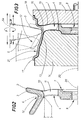
- Figure 4 illustrates a wheel rim obtained using the process illustrated in Figs. 1, 2 and 3.
- With reference to the drawings listed above, the process for the forming of metal alloy wheel rims 1 envisages that an unworked piece or blank 2 be obtained by a casting process in which aluminium alloy billets are melted and the molten metal is then poured into the cavity of the die 8 of the blank 2. The blank 2 thus obtained is approximately in the shape of a double Y, in diametral cross section, with nearly constant thickness in all the branches of the Y section. This type of section avoids problems that may arise when thicknesses differ on account of nonuniform cooling of the blank.
- When the time necessary to solidify the alloy has elapsed, the blank 2 is extracted from the die 8 and cold machined. The cold machining process (refer to Fig. 2) envisages a first chip removal operation in which the blank is rotated about its
axis 20 and material cut away from itscentral portion 9, to make the hole for the hub, from the inner surface 4 of the blank 2 and from thelateral surface 12 of the blank 2. For clarity, the said first machining process is shown with a dashed line in Fig. 2. This machining process removes material from the blank 2 to generate a reference surface for subsequent machine operations and, at the same time, creates a blank of defined dimensions which hereinafter will be referred to as semi-finished work 3. - The reason for this first machine operation is that the casting process cannot guarantee a constant volume of material in all sections of the blank. The material must, however, be distributed uniformly all round the blank, that is to say, the allowance on the entire circumferential surface of the blank must be the same.
- In this regard, it must be stressed that it is very important to guarantee that there are constant volumes of material distributed uniformly along the entire circumference of the blank 2. In fact, this is essential to enable the subsequent compression process known technically as "flow forming", to be carried out on the blank 2, this being a process which requires uniform thicknesses along the entire surface of the blank 2. If the thicknesses are different, the flow forming process applies nonuniform forces to the blank while it is being rotated. This gives rise to vibrations and knocking, preventing the process from proceeding correctly and worsening the quality of the result. In such an event, the subsequent removal of excess burrs would require further processing, on a lathe, for example. Moreover, since the excess burrs would not be distributed uniformly, even lathing would be hampered by the resulting shocks and vibrations. In all events, therefore, it is very important that the total volume of material of the semi-finished work 3, including the uniformly distributed machining allowance, is within well-defined limits so as to avoid burring due to excess material, which would have to be removed by further machining.
- In short, the subsequent flow-forming process is a constant volume process where the work has to have a well-defined, constant volume of material to start with.
- The lathe turning process on the
lateral surface 12 also creates a groove 6 (see Fig. 2) whose shape matches the outer profile of aflow forming roller 5. The purpose of this groove is explained in more detail below. - Next, the semi-finished work 3, that is, the one shown with the dashed line in Figs. 2 and 3, is heated in a furnace to a temperature of preferably 380° to 400°C. During the subsequent flow forming process, the semi-finished work 3 heated in this way can be plastically deformed more easily and using less energy. Heating also avoids the problem of cracking which often arises in cold machining processes. Moreover, combined with the subsequent flow forming, it contributes to the elimination of casting defects.
- After being heated, the semi-finished work 3 is fixed to a
spindle 14 of a special flow forming lathe and locked in place by atailstock 15 which rests against thefront 19 of the rim 1, the outer shape of thespindle 14 substantially corresponding to the required end shape of the inner surface 4 of the rim 1. The semi-finished work 3 and thespindle 14 are turned about an axis which corresponds to the axis ofrotation 20 of the rim. In this way, the subsequent flow forming process on thelateral surface 12 of the rim guarantees the concentricity of thelateral surface 12 with the axis ofrotation 20. - The semi-finished work 3 is machined by flow forming on the areas constituted by the
lateral surface 12 to create achannel 21 with aninner edge 17, anouter edge 18 and amiddle portion 13, leaving a defined machining allowance depending on the subsequent heat treatments. - The flow forming process consists of a series of axial-symmetric forming operations whereby a rotating workpiece is compressed into shape by a suitable
rolling tool 5 which rolls the material down to a predefined thickness. - The
roller 5, only a half of which is illustrated in Fig. 3, should preferably be made of hardened steel and be rotated about itsaxis 5a by a known type of drive motor so that its peripheral speed is the same as that of the surface of the semi-finished work 3 so as to prevent the development of considerable tangential forces due to tangential friction between the two surfaces. - Initially, the
roller 5 is inserted into thegroove 5, made previously by the cold machining process, without compressing the lateral surface of the rim 1. It is necessary to proceed in this way because the rim, in the area of thedisc 7, usually consists of an alternate sequence ofspokes 10, that is, parts full of material, andgaps 11, that is, spaces free of material. If theroller 5 is inserted into thelateral surface 12 in an area corresponding to agap 11, the thickness of thewall 16 is relatively small and contrasts the compressive action of the roller. Therefore, if the groove 6 is not made by cutting away material but by compression instead, thewall 16 of thelateral surface 12 would buckle. Nor would it possible to support thewall 16 of thelateral surface 12 in the area corresponding to thegap 11 since thetailstock 15 rests only against thefront 19 of the rim and it would be extremely complicated to construct a tailstock to fit exactly into thegaps 11 of the rim 1 so as to provide adequate support for thewall 16 of thelateral surface 12. The groove 6 is also necessary to start the flow forming process on the lateral surface since the material must be rolled down to the required, smaller thickness in a single pass of theroller 5. According to a general embodiment, when theroller 5 is inserted into the groove 6 it moves sideways first in the direction of thefront 19 of the rim 1, thus forming theouter edge 18, and then, after being inserted into the groove 6 again, moves sideways in the direction opposite thefront 19, so as to form theinner edge 17 and themiddle portion 13. - According to another embodiment, the
outer edge 18 of the rim 1 is made beforehand at the casting stage because its axial dimensions are considerably smaller than those of theinner edge 17 and themiddle portion 13. In this case, the flow forming process on theouter edge 18 is omitted and this part is only cold processed by removal of material It should be noted that the profile of thelateral surface 12 of theroller 5 is formed by the combination of the two movements of theroller 5 in the axial and tangential directions with respect to the rim 1; the roller is driven preferably by a computer numerical control (CNC) system. - The compression generated by the flow process on the heated material squeezes out typical casting defects such as microporosity and microshrinkage and, in so doing, greatly improves the mechanical properties of the material. In particular, the
wall 16 of thelateral surface 12 of the rim may be made considerably thinner than the corresponding wall of a rim obtained by casting. Moreover, the flow forming process totally eliminates the problem of air leaks through microporosity in the rim material, this being a significant improvement if one considers that practically all tyres currently made are tubeless. - The process described above should preferably be followed by a solution heat treatment designed to hold, that is, retain the solid solution of the previously heated alloy. This treatment homogenizes the structure of the material deformed by the earlier flow forming process and relieves internal stress, especially in the area where the
lateral surface 12 joins thedisc 7. The solution heat treatment may be followed by age hardening in order to further improve the mechanical properties of the alloy. - These heat treatments, however, cause dimensional and geometrical variations in the rim. It is therefore necessary to leave a certain amount of machine allowance so that the rim can be worked down to the required size and shape by a suitable chip removal process.
- The rim is then cold processed by cutting material away from the entire
lateral surface 12, including theinner edge 17, theouter edge 18 and themiddle portion 13, to remove the machining allowance left by the earlier flow forming process and to work the rim down to the required size. This process should preferably be performed using a diamond cutting tool capable of dealing with the considerable hardness of the alloy following the age hardening treatment and of producing a fine surface finish. The latter mechanical process also guarantees the perfect static and dynamic balance of the rim. - Finally, the holes for fixing the rim to the hub and the hole for the valve are made in the rim using known methods.
- Although the manufacturing process described above is relatively simple, the rims 1 obtained in this way, illustrated in Fig. 4, have similar mechanical properties to forged rims and are better quality than cast rims.
- The invention described can be subject to modifications and variations without thereby departing from the scope of the inventive concept. Moreover, all the details of the invention may be substituted by technically equivalent elements.
Claims (6)
- A process for the forming of wheel rims (1) in metal alloy of the kind consisting of a disc (7) from which an alternating sequence of spokes (10) and gaps (11) is made and of a lateral surface (12) defined by a middle portion (13) delimited by an inner edge (17) and an outer edge (18), characterized in that it comprises the following stages at least:- obtaining a blank (2) by a casting process;- mechanically cold processing the blank by cutting material away from its central area (9), from the inner surface (4) of the disc (7) and from its lateral surface (12);- heating the semi-finished work (3) in a furnace;- fixing the heated semi-finished work (3) across a spindle (14) and a tailstock (15);- turning the spindle (14) and the semi-finished work (3) about an axis corresponding to the axis of rotation of the rim (1);- flow forming by passing a roller (5) over the areas constituted by the lateral surface (12) of the semi-finished work (3) to create a channel (21) with an inner edge (17), an outer edge (18) and a middle portion (13), leaving a defined machining allowance depending on the subsequent heat treatments;- mechanically cold processing the rim by cutting material away from the lateral surface (12), including the inner edge (17), the outer edge (18) and the middle portion (13), to remove the machining allowance left by the earlier flow forming process and to work the rim down to the required size.
- The process according to claim 1, characterized in that the cold mechanical process that precedes the flow forming process and that cuts material away from the blank creates a groove (6) that substantially matches the shape of the outer profile of a flow forming roller (5).
- The process according to claim 1, characterized in that the flow forming process on the lateral surface (12) is performed using a lathe whose spindle (14) has an outer profile that substantially corresponds to the required end profile of the inner surface (4) of the rim.
- The process according to claim 3, characterized in that the cold mechanical process whereby material is cut away from the lateral surface (12) and that follows the flow forming process is preceded by a solution heat treatment.
- The process according to claim 4, characterized in that the solution heat treatment is followed by an age hardening treatment.
- A metal alloy wheel rim characterized in that it is made according to the process claimed in one of the foregoing claims.
Applications Claiming Priority (2)
| Application Number | Priority Date | Filing Date | Title |
|---|---|---|---|
| IT95BO000460A IT1279738B1 (en) | 1995-09-29 | 1995-09-29 | METAL ALLOY WHEEL RIMS FORMING PROCESS |
| ITBO950460 | 1995-09-29 |
Publications (2)
| Publication Number | Publication Date |
|---|---|
| EP0765700A1 true EP0765700A1 (en) | 1997-04-02 |
| EP0765700B1 EP0765700B1 (en) | 1999-03-31 |
Family
ID=11340829
Family Applications (1)
| Application Number | Title | Priority Date | Filing Date |
|---|---|---|---|
| EP96830479A Expired - Lifetime EP0765700B1 (en) | 1995-09-29 | 1996-09-25 | A process for the forming of metal alloy wheel rims |
Country Status (7)
| Country | Link |
|---|---|
| US (1) | US5772801A (en) |
| EP (1) | EP0765700B1 (en) |
| AT (1) | ATE178234T1 (en) |
| CA (1) | CA2186421A1 (en) |
| DE (1) | DE69601911T2 (en) |
| ES (1) | ES2130774T3 (en) |
| IT (1) | IT1279738B1 (en) |
Cited By (3)
| Publication number | Priority date | Publication date | Assignee | Title |
|---|---|---|---|---|
| EP1016477A2 (en) * | 1998-12-28 | 2000-07-05 | Mazda Motor Corporation | Light metal forging material manufacturing method and forged member manufacturing method using the material |
| EP3932581A1 (en) * | 2020-06-29 | 2022-01-05 | Yamaha Hatsudoki Kabushiki Kaisha | Method of producing a wheel for straddled vehicles and flow forming apparatus |
| EP3932580A1 (en) * | 2020-06-29 | 2022-01-05 | Yamaha Hatsudoki Kabushiki Kaisha | Method of producing a wheel for straddled vehicles |
Families Citing this family (14)
| Publication number | Priority date | Publication date | Assignee | Title |
|---|---|---|---|---|
| DE10141510A1 (en) * | 2001-08-24 | 2003-03-13 | Audi Ag | Process for the production of light alloy rims |
| US7270382B2 (en) * | 2003-10-21 | 2007-09-18 | Hodges Frank J | Wheel with increased interior lip depth |
| US7228629B2 (en) * | 2003-11-10 | 2007-06-12 | Beyer Michael J | Method of spin forming an automotive wheel rim |
| US7581315B2 (en) | 2004-11-16 | 2009-09-01 | Mahle Technology, Inc. | Connecting rod assembly for an internal combustion engine and method of manufacturing same |
| US7516546B2 (en) * | 2004-11-16 | 2009-04-14 | Mahle Technology, Inc. | Method of manufacturing a connecting rod assembly for an internal combustion engine |
| US8613137B2 (en) | 2004-11-16 | 2013-12-24 | Mahle International Gmbh | Connecting rod lubrication recess |
| US20090113713A1 (en) * | 2007-11-01 | 2009-05-07 | Wang-Fa Tsai | Method for Making a Wheel Rim |
| US20110018335A1 (en) * | 2009-07-21 | 2011-01-27 | Hodges Frank J | Wheel component covering |
| US8919890B2 (en) * | 2009-11-02 | 2014-12-30 | Segiu Anca | Wheel with increased interior lip depth |
| US9023431B2 (en) * | 2011-09-19 | 2015-05-05 | Basf Se | Method for coating light alloy rims |
| US10442241B2 (en) * | 2013-09-05 | 2019-10-15 | GM Global Technology Operations LLC | Methods and apparatus to produce high performance axisymmetric components |
| CN103551461B (en) * | 2013-10-31 | 2015-04-29 | 刘湘平 | Special mold for rim spinning device |
| GB2568857B (en) * | 2017-09-05 | 2020-12-30 | Nissan Motor Mfg Uk Ltd | Method of toolpath generation for a spin forming process |
| DE102020127595A1 (en) | 2020-07-02 | 2022-01-05 | Dr. Ing. H.C. F. Porsche Aktiengesellschaft | CAST WHEEL WITH A ROTATION AXLE FOR A MOTOR VEHICLE |
Citations (5)
| Publication number | Priority date | Publication date | Assignee | Title |
|---|---|---|---|---|
| US4528734A (en) | 1982-07-08 | 1985-07-16 | Ni Industries, Inc. | Method of spin forging a vehicle wheel |
| US4579604A (en) * | 1982-07-08 | 1986-04-01 | Ni Industries, Inc. | Method of spin forging a finished article |
| US4624038A (en) * | 1983-09-16 | 1986-11-25 | Walther William D | Method of producing motor vehicle wheels |
| DE3801104A1 (en) * | 1988-01-16 | 1989-08-03 | Lemmerz Werke Kgaa | Method for the production of a light-alloy wheel |
| EP0366049A2 (en) * | 1988-10-24 | 1990-05-02 | Asahi Tec Corporation | Spinning molding process, spinning molding apparatus, spinning molding raw material, spinning molding process of vehicle wheel, and spinning molding apparatus of vehicle wheel |
Family Cites Families (1)
| Publication number | Priority date | Publication date | Assignee | Title |
|---|---|---|---|---|
| JP2676466B2 (en) * | 1992-09-30 | 1997-11-17 | マツダ株式会社 | Magnesium alloy member and manufacturing method thereof |
-
1995
- 1995-09-29 IT IT95BO000460A patent/IT1279738B1/en active IP Right Grant
-
1996
- 1996-09-23 US US08/717,717 patent/US5772801A/en not_active Expired - Lifetime
- 1996-09-25 EP EP96830479A patent/EP0765700B1/en not_active Expired - Lifetime
- 1996-09-25 ES ES96830479T patent/ES2130774T3/en not_active Expired - Lifetime
- 1996-09-25 AT AT96830479T patent/ATE178234T1/en not_active IP Right Cessation
- 1996-09-25 DE DE69601911T patent/DE69601911T2/en not_active Expired - Fee Related
- 1996-09-25 CA CA002186421A patent/CA2186421A1/en not_active Abandoned
Patent Citations (6)
| Publication number | Priority date | Publication date | Assignee | Title |
|---|---|---|---|---|
| US4528734A (en) | 1982-07-08 | 1985-07-16 | Ni Industries, Inc. | Method of spin forging a vehicle wheel |
| US4579604A (en) * | 1982-07-08 | 1986-04-01 | Ni Industries, Inc. | Method of spin forging a finished article |
| US4624038A (en) * | 1983-09-16 | 1986-11-25 | Walther William D | Method of producing motor vehicle wheels |
| DE3801104A1 (en) * | 1988-01-16 | 1989-08-03 | Lemmerz Werke Kgaa | Method for the production of a light-alloy wheel |
| EP0366049A2 (en) * | 1988-10-24 | 1990-05-02 | Asahi Tec Corporation | Spinning molding process, spinning molding apparatus, spinning molding raw material, spinning molding process of vehicle wheel, and spinning molding apparatus of vehicle wheel |
| US5092040A (en) | 1988-10-24 | 1992-03-03 | Asahi Malleable Iron Co., Ltd. | Spin molding process for manufacturing a vehicle wheel |
Cited By (4)
| Publication number | Priority date | Publication date | Assignee | Title |
|---|---|---|---|---|
| EP1016477A2 (en) * | 1998-12-28 | 2000-07-05 | Mazda Motor Corporation | Light metal forging material manufacturing method and forged member manufacturing method using the material |
| EP1016477A3 (en) * | 1998-12-28 | 2001-03-14 | Mazda Motor Corporation | Light metal forging material manufacturing method and forged member manufacturing method using the material |
| EP3932581A1 (en) * | 2020-06-29 | 2022-01-05 | Yamaha Hatsudoki Kabushiki Kaisha | Method of producing a wheel for straddled vehicles and flow forming apparatus |
| EP3932580A1 (en) * | 2020-06-29 | 2022-01-05 | Yamaha Hatsudoki Kabushiki Kaisha | Method of producing a wheel for straddled vehicles |
Also Published As
| Publication number | Publication date |
|---|---|
| ES2130774T3 (en) | 1999-07-01 |
| DE69601911D1 (en) | 1999-05-06 |
| DE69601911T2 (en) | 1999-08-05 |
| US5772801A (en) | 1998-06-30 |
| CA2186421A1 (en) | 1997-03-30 |
| ITBO950460A1 (en) | 1995-12-29 |
| EP0765700B1 (en) | 1999-03-31 |
| IT1279738B1 (en) | 1997-12-16 |
| ATE178234T1 (en) | 1999-04-15 |
Similar Documents
| Publication | Publication Date | Title |
|---|---|---|
| EP0765700B1 (en) | A process for the forming of metal alloy wheel rims | |
| JPS63251128A (en) | Manufacture of ring gear | |
| CN109048241B (en) | Method for forging input shaft of automobile gearbox and rough machining and forming blank of input shaft | |
| US4606206A (en) | Method and apparatus for edge preparation of spinning blanks | |
| JPS63214564A (en) | Manufacture of ring gear quasi-forged part | |
| US5689882A (en) | Method of producing a rear wheel spindle | |
| JPS63215331A (en) | Method for forging series of ring roll preform and forging mold therefor | |
| US3822458A (en) | Method of making wheels | |
| EP0509610A1 (en) | Procedure for production of vehicle wheels | |
| EP1158194B1 (en) | Process for forming steel roller bearings | |
| US5577323A (en) | Method of manufactoring a race ring for a rolling bearing | |
| WO1998003281A1 (en) | Process for spin forming a vehicle wheel | |
| JP3503816B2 (en) | Bevel gear with web cold forging die and method of manufacturing bevel gear with web | |
| JP3954104B2 (en) | Method for forming spun or twisted ring and spun or twisted ring manufactured without cutting | |
| JPS63134B2 (en) | ||
| KR101449270B1 (en) | Method for manufacturing extruded helical gear having postprocess of extruded helical gear | |
| CN113941678B (en) | Forging process for hub sleeve warm forging and cold extrusion and die thereof | |
| JP2596688B2 (en) | Manufacturing method of light alloy wheel | |
| JPS61147935A (en) | Manufacture of mono-black wheel | |
| JPH11254080A (en) | Forging apparatus, and forging method | |
| JP2003019534A (en) | Circular work forging method | |
| JP3746828B2 (en) | Manufacturing method for cylindrical parts | |
| US20080273936A1 (en) | Method for Producing Rotationally Symmetrical, undercut Contours | |
| RU2245210C2 (en) | Method of producing elastic hanger of dynamically tuned gyro | |
| JPH08112639A (en) | Formation of outer gear with chamfer |
Legal Events
| Date | Code | Title | Description |
|---|---|---|---|
| PUAI | Public reference made under article 153(3) epc to a published international application that has entered the european phase |
Free format text: ORIGINAL CODE: 0009012 |
|
| AK | Designated contracting states |
Kind code of ref document: A1 Designated state(s): AT BE DE ES GB IT |
|
| 17P | Request for examination filed |
Effective date: 19970715 |
|
| 17Q | First examination report despatched |
Effective date: 19971021 |
|
| RIN1 | Information on inventor provided before grant (corrected) |
Inventor name: EDWARDS, DAVID J., C/O REYNOLDS WHEELS S.P.A. Inventor name: BALDI, VALTER |
|
| GRAG | Despatch of communication of intention to grant |
Free format text: ORIGINAL CODE: EPIDOS AGRA |
|
| GRAG | Despatch of communication of intention to grant |
Free format text: ORIGINAL CODE: EPIDOS AGRA |
|
| GRAH | Despatch of communication of intention to grant a patent |
Free format text: ORIGINAL CODE: EPIDOS IGRA |
|
| GRAH | Despatch of communication of intention to grant a patent |
Free format text: ORIGINAL CODE: EPIDOS IGRA |
|
| GRAA | (expected) grant |
Free format text: ORIGINAL CODE: 0009210 |
|
| AK | Designated contracting states |
Kind code of ref document: B1 Designated state(s): AT BE DE ES GB IT |
|
| REF | Corresponds to: |
Ref document number: 178234 Country of ref document: AT Date of ref document: 19990415 Kind code of ref document: T |
|
| ITF | It: translation for a ep patent filed |
Owner name: BUGNION S.P.A. |
|
| REF | Corresponds to: |
Ref document number: 69601911 Country of ref document: DE Date of ref document: 19990506 |
|
| REG | Reference to a national code |
Ref country code: ES Ref legal event code: FG2A Ref document number: 2130774 Country of ref document: ES Kind code of ref document: T3 |
|
| PLBE | No opposition filed within time limit |
Free format text: ORIGINAL CODE: 0009261 |
|
| STAA | Information on the status of an ep patent application or granted ep patent |
Free format text: STATUS: NO OPPOSITION FILED WITHIN TIME LIMIT |
|
| 26N | No opposition filed | ||
| REG | Reference to a national code |
Ref country code: GB Ref legal event code: IF02 |
|
| PGFP | Annual fee paid to national office [announced via postgrant information from national office to epo] |
Ref country code: GB Payment date: 20030924 Year of fee payment: 8 |
|
| PGFP | Annual fee paid to national office [announced via postgrant information from national office to epo] |
Ref country code: AT Payment date: 20030926 Year of fee payment: 8 |
|
| PGFP | Annual fee paid to national office [announced via postgrant information from national office to epo] |
Ref country code: DE Payment date: 20031002 Year of fee payment: 8 |
|
| PGFP | Annual fee paid to national office [announced via postgrant information from national office to epo] |
Ref country code: ES Payment date: 20031030 Year of fee payment: 8 |
|
| PGFP | Annual fee paid to national office [announced via postgrant information from national office to epo] |
Ref country code: BE Payment date: 20031208 Year of fee payment: 8 |
|
| PG25 | Lapsed in a contracting state [announced via postgrant information from national office to epo] |
Ref country code: GB Free format text: LAPSE BECAUSE OF NON-PAYMENT OF DUE FEES Effective date: 20040925 Ref country code: AT Free format text: LAPSE BECAUSE OF NON-PAYMENT OF DUE FEES Effective date: 20040925 |
|
| PG25 | Lapsed in a contracting state [announced via postgrant information from national office to epo] |
Ref country code: ES Free format text: LAPSE BECAUSE OF NON-PAYMENT OF DUE FEES Effective date: 20040927 |
|
| PG25 | Lapsed in a contracting state [announced via postgrant information from national office to epo] |
Ref country code: BE Free format text: LAPSE BECAUSE OF NON-PAYMENT OF DUE FEES Effective date: 20040930 |
|
| BERE | Be: lapsed |
Owner name: *REYNOLDS WHEELS S.P.A. Effective date: 20040930 |
|
| PG25 | Lapsed in a contracting state [announced via postgrant information from national office to epo] |
Ref country code: DE Free format text: LAPSE BECAUSE OF NON-PAYMENT OF DUE FEES Effective date: 20050401 |
|
| GBPC | Gb: european patent ceased through non-payment of renewal fee |
Effective date: 20040925 |
|
| PG25 | Lapsed in a contracting state [announced via postgrant information from national office to epo] |
Ref country code: IT Free format text: LAPSE BECAUSE OF NON-PAYMENT OF DUE FEES;WARNING: LAPSES OF ITALIAN PATENTS WITH EFFECTIVE DATE BEFORE 2007 MAY HAVE OCCURRED AT ANY TIME BEFORE 2007. THE CORRECT EFFECTIVE DATE MAY BE DIFFERENT FROM THE ONE RECORDED. Effective date: 20050925 |
|
| REG | Reference to a national code |
Ref country code: ES Ref legal event code: FD2A Effective date: 20040927 |
|
| BERE | Be: lapsed |
Owner name: *REYNOLDS WHEELS S.P.A. Effective date: 20040930 |