EP3932508B1 - Body mounting system for a model vehicle - Google Patents
Body mounting system for a model vehicle Download PDFInfo
- Publication number
- EP3932508B1 EP3932508B1 EP21183318.1A EP21183318A EP3932508B1 EP 3932508 B1 EP3932508 B1 EP 3932508B1 EP 21183318 A EP21183318 A EP 21183318A EP 3932508 B1 EP3932508 B1 EP 3932508B1
- Authority
- EP
- European Patent Office
- Prior art keywords
- mount
- model vehicle
- chassis
- mounting system
- vehicle body
- Prior art date
- Legal status (The legal status is an assumption and is not a legal conclusion. Google has not performed a legal analysis and makes no representation as to the accuracy of the status listed.)
- Active
Links
Images



Classifications
-
- A—HUMAN NECESSITIES
- A63—SPORTS; GAMES; AMUSEMENTS
- A63H—TOYS, e.g. TOPS, DOLLS, HOOPS OR BUILDING BLOCKS
- A63H17/00—Toy vehicles, e.g. with self-drive; ; Cranes, winches or the like; Accessories therefor
- A63H17/26—Details; Accessories
- A63H17/262—Chassis; Wheel mountings; Wheels; Axles; Suspensions; Fitting body portions to chassis
-
- A—HUMAN NECESSITIES
- A63—SPORTS; GAMES; AMUSEMENTS
- A63H—TOYS, e.g. TOPS, DOLLS, HOOPS OR BUILDING BLOCKS
- A63H17/00—Toy vehicles, e.g. with self-drive; ; Cranes, winches or the like; Accessories therefor
- A63H17/002—Toy vehicles, e.g. with self-drive; ; Cranes, winches or the like; Accessories therefor made of parts to be assembled
-
- A—HUMAN NECESSITIES
- A63—SPORTS; GAMES; AMUSEMENTS
- A63H—TOYS, e.g. TOPS, DOLLS, HOOPS OR BUILDING BLOCKS
- A63H17/00—Toy vehicles, e.g. with self-drive; ; Cranes, winches or the like; Accessories therefor
- A63H17/26—Details; Accessories
- A63H17/264—Coupling mechanisms
Definitions
- Radio-Controlled or RC model vehicles are a popular hobby for a growing segment of the population.
- electrically powered vehicles as the electronics become more sophisticated and the batteries more advanced, the ease of operation and the run time of RC model vehicles have increased dramatically.
- one area that has fallen behind in terms of ease of operation is the removal and attachment of a model vehicle body to a model vehicle chassis.
- US 3 653 149 A1 relates to a toy vehicle body simulating a high performance vehicle.
- the toy vehicle body is hingedly attached to a toy vehicle chassis and a body support member is hingedly attached to the toy vehicle chassis to support the toy vehicle body above the toy vehicle chassis to allow the exposure of the toy vehicle's engine and interior assembly, when desired.
- US 2 141 267 A1 relates to a vehicle in which a body structure is pivotally mounted on a chassis structure to provide a vehicle having a body structure movably connected to a chassis structure of the vehicle.
- the vehicle is provided with a hydraulic brake cylinder together with a brake pedal for operating the same, the combination of a main frame assembly, a rock shaft mounted on said main frame assembly, a lever member fixedly mounted on said rock shaft and pivotally connected with said hydraulic brake cylinder, an idler lever pivotally mounted on said main frame assembly, a second lever member fixedly mounted on said rock shaft, a rod member pivotally connected with said second lever member and said idler lever, a collar member fixedly mounted on said rod member, an auxiliary frame assembly pivotally supported on said main frame assembly, and a forked lever member pivotally mounted on said auxiliary frame assembly and adapted to straddle said rod member and engage said collar member, said forked lever being connected with said brake pedal.
- a model vehicle comprising a model vehicle chassis, a model vehicle body, and a body mounting system.
- the body mounting system comprises a first mount pivotally connected to a first end of the model vehicle body and a second mount connected to a second end of the model vehicle body located opposite to the first end.
- the first mount releasably couples the first end of the model vehicle body to the model vehicle chassis and the model vehicle body is pivoted about a rotation point and releasably coupled to the model vehicle chassis via the second mount.
- a model vehicle comprising a model vehicle chassis, a model vehicle body comprising a body support mechanism, and a body mounting system.
- the body mounting system comprises a first mount pivotally connected to a first end of the model vehicle body via the body support mechanism and a second mount connected to a second end of the model vehicle body located opposite to the first end via the body support mechanism.
- the first mount releasably couples the first end of the model vehicle body to the model vehicle chassis in a first direction.
- the second end of the model vehicle body is rotated about the pivotal connection and the second mount releasably couples the second end of the model vehicle body to the model vehicle chassis in a second direction.
- a body mounting system for a model vehicle comprising a first mount and a second mount.
- the first mount comprises a first body mount and a first chassis mount.
- the first body mount comprises a first support and a first latch.
- the first chassis mount comprises a first support receptacle a first latch receptacle.
- the second mount comprises a second body mount and a second chassis mount.
- the second body mount comprises a second support and a second latch.
- the second chassis mount comprises a second support receptacle and a second latch receptacle.
- Radio Controlled (RC) model vehicles usually comprise a scale version of a model vehicle body coupled to a model vehicle chassis.
- the model vehicle chassis contains the electronics, batteries, and servos required for operating an RC model vehicle.
- the model vehicle body must be removed in order to activate and deactivate the Electronic Speed Control (ESC), or to charge, replace, or connect a battery pack. And during operation, the model vehicle body must remain securely coupled to the model vehicle chassis while the vehicle is run in a variety of conditions and circumstances.
- ESC Electronic Speed Control
- RC model vehicles typically comprise mounting posts coupled to a model vehicle chassis with protruding pins located at the top of each of the posts.
- the mounting posts are typically vertical relative to the horizontal model vehicle chassis.
- the model vehicle body is provided with a number of pin holes corresponding to the protruding pins.
- Each of the protruding pins include clip holes and body support pads.
- the model vehicle body In order to secure a model vehicle body to a model vehicle chassis, the model vehicle body lowered vertically over the mounting posts and the protruding pins.
- the protruding pins pass through the corresponding pin holes until the interior of the model vehicle body rests on the body support pads.
- the protruding pins extend through the model vehicle body to the point where the clip holes are located external to the model vehicle body.
- Clips are then inserted into the pins holes provided in the protruding pins, retaining the model vehicle body in position relative to the model vehicle chassis.
- FIG. 1 shows an embodiment of a model vehicle 100 including a transparent model vehicle body 200 and a model vehicle chassis 300.
- the model vehicle 100 further comprises a body mounting system that includes a first mount 400 and a second mount 500.
- the first mount 400 and the second mount 500 will be described later in more detail.
- FIG. 1 shows the model vehicle body 200 and the model vehicle chassis 300 in their assembled, ready to operate configuration, with both the first mount 400 and the second mount 500 in releasably coupled configurations.
- FIG. 2 this figure shows an exemplary embodiment of the model vehicle 100 as shown in FIG. 1 , but in a partially opened configuration.
- the first mount 400 has been releasably coupled to the model vehicle chassis 300 via a latch, and the second mount 500 is open or uncoupled.
- the model vehicle body 200 would have to be rotated in a clockwise manner until the second mount 500 is releasably coupled with the model vehicle chassis 300 via a latch.
- auxiliary mount 600 also shown in this exemplary embodiment is an auxiliary mount 600.
- the auxiliary mount 600 in this case comprises auxiliary mounting posts 610, protruding pins 620, clips 630, and body support pads 640. Other embodiments may not have this auxiliary mount 600 depending upon the application.
- the stiffness and type of model vehicle body 200 and model vehicle chassis 300 may be enough to only use a first mount 400 and a second mount 500.
- the clips 630 are removed from the protruding pins 620.
- the protruding pins 620 extend through the mounting holes (not visible in this view) of the model vehicle body 200 until an interior surface of the model vehicle body 200 rests upon the body support pads 640.
- the model vehicle body 200 is releasably secured in operational position by inserting clips 630 through the protruding pins 620.
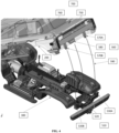
- FIG. 3 shows a lower, rear, right enlarged perspective assembly view of the model vehicle body 200, the model vehicle chassis 300, and the first mount 400.
- the first mount 400 includes the first body mount 460 and the first chassis mount 410.
- the first body mount 460 is pivotally coupled to the model vehicle body 200 and the first chassis mount 410 is fixedly coupled to the model vehicle chassis 300.
- first body mount 460 is shown as being pivotally coupled to the model vehicle body and the first chassis mount 410 is shown as being fixedly coupled to the model vehicle chassis 300, the pivoting and fixed nature of these mounts could be reversed and the pivot provided between the model vehicle chassis 300 and the first chassis mount 410.
- the description will refer to the current configuration as representative of other configurations.
- first body mount 460 and the first chassis mount 410 are illustrated at the front of the model vehicle body and the model vehicle chassis, they could have easily been located at the opposite ends of both of these assemblies. Both the location of the first mount and whether the pivot is provided between the model vehicle body or the model vehicle chassis are matters of application and should both be within the scope of the current disclosure.
- the first mount 400 in this figure is shown prior to the releasable coupling of first body mount 460 with the first chassis mount 410.
- the model vehicle body 200 is completely separate from the model vehicle chassis 300.
- the first body mount 460 is inserted into the first chassis mount 410 in a first direction 490 as shown by the arrows.
- the arrows represent an exemplary horizontal direction for the first direction 490, but the teachings of this disclosure should not be limited to this single illustrative orientation.
- the first body mount 460 further includes first latches 480A and 480B.
- the first latches 480A and 480B each have a retention tab 485. During the connection of the first body mount 460 to the first chassis mount 410, the first latches 480A and 480B are inserted into a first latch receptacle 420 of the first chassis mount 410.
- the retention tabs 485 resiliently interact with the side walls of the first latch receptacle 420 to inhibit the removal of the first body mount 460 from the first chassis mount 410.
- the two first latches 480A and 480B are resiliently bent towards one another, thereby releasing the retention tabs 485 from the side walls of the first latch receptacle 420.
- While a snap fit latching mechanism is shown as the configuration for the releasable coupling of the first body mount 460 to the first chassis mount 410, other releasable configurations may be used by a person of skill in the art in accordance with the teachings of this disclosure. For example, single first latches, toggle draw latches, and butterfly twist latches, can be used among others.
- the first body mount 460 also comprises first supports 470A and 470B. While two first latches 480A and 480B and two first supports 470A and 470B are shown in this illustrative example, the actual number and configuration of the latches and supports may be selected according to the particular application of the first mount 400.
- First supports 470A and 470B differ from the first latches 480A and 480B in that they are relatively more rigid and configured to provide strength and stability to the releasable connection between the first body mount 460 and the first chassis mount 410.
- the first supports 470A and 470B are shown as rectangular protrusions with a square cross-section.
- the actual configuration and geometry of the first supports 470A and 470B may be selected based upon a specific application.
- the first supports 470A and 470B may be conical, cylindrical, polygonal, or made of different materials among others.
- the first supports 470A and 470B are configured to securely fit within a corresponding number of first support receptacles 430A and 430B (only first support receptacle 430A is visible in this view).
- the first supports 470A and 470B are inserted into the first support receptacles 430A and 430B in the first direction 490 and provide additional strength and support for the first body mount 460 and first chassis mount 410 about a first plane perpendicular to the first direction 490.
- the first supports 470A and 470B engagement with the first support receptacles 430A and 430B will have their greatest resistance to forces impacting the model vehicle body 200 relative to the model vehicle chassis 300 in a first plane that extends vertically and from either side (e.g., perpendicular) to the first direction 490.
- a body support mechanism 700 In some cases the model vehicle body 200 will be rigid or durable enough to allow the first body mount 460 to directly attach to an end of the model vehicle body 200. However, in other cases, a model vehicle body 200 for a model vehicle 100 may be made of a lightweight, thin plastic material. In these cases, an additional body support mechanism 700 may be used to strengthen or reinforce the model vehicle body 200, as well as to distribute the loading from either the first and/or second mount 400, 500 across or about the model vehicle body 200.
- the body support mechanism 700 may include one or both of a separate front body support mechanism 740 and a rear body support mechanism 750 (not visible in this figure). As described in the current disclosure, one body support mechanism 700 may extend along the length of the model vehicle body 200 and tie the first mount 400 to the second mount 500 via a body support structure 760. As seen in FIG. 3 , first body mount 460 is pivotally coupled to first body support mechanism 740 via a first pivoting coupling 465.
- the first pivoting coupling 465 allows the first body support mechanism 740 and the attached model vehicle body 200 to pivot relative to the front body mount 460. While the illustrated exemplary first pivoting coupling 465 uses two hinges, other types of coupling the first body mount 460 to the first body support mechanism 740 may be used. For example, in some cases a single hinged connection or a resiliently bendable connection made via a resiliently deformable flexible material such as an elastomer silicone rubber or Ethylene Propylene Diene Monomer EPDM, among others, may be used for the pivotal couple.
- a single hinged connection or a resiliently bendable connection made via a resiliently deformable flexible material such as an elastomer silicone rubber or Ethylene Propylene Diene Monomer EPDM, among others, may be used for the pivotal couple.
- this illustrative embodiment has a single body support mechanism 700 coupling the first mount 400 to the second mount 500, a portion of the body support structure 760 is attached to the first body support mechanism 740 and shown in this view.
- the model vehicle body 200 is fixedly coupled to the body support mechanism 700 in an appropriate manner, i.e., mechanical fasteners, adhesive, and plastic welding, among others.
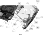
- FIG. 4 shows the second mount 500 in an uncoupled, open configuration prior to coupling the second body mount 560 to the second chassis mount 510.
- An exemplary illustration showing the second body mount 500 in a coupled, closed configuration is seen in FIG. 5 .
- the model vehicle body 200 is pivotally coupled to the model vehicle chassis 300 via the first mount 400.
- the model vehicle body 200 is rotated about the pivot point in the first mount 400 so that the second body mount 560 engages the second chassis mount 510 in a second direction 590 (shown by the arrows in FIG. 4 ).
- the second direction 590 is determined at the approximate point of rotation of the model vehicle body 200 when the second body mount 560 initiates engagement with the second chassis mount 510. Generally at this point during the rotation, the second direction 590 is substantially perpendicular (e.g., in the vertical direction to within a few degrees) to the first direction 490.
- first mount 400 and the second mount 500 Having two separate mounting directions, such as the first direction 490 (e.g., approximately horizontal) and the second direction 590 (e.g., approximately vertical), results in the first mount 400 and the second mount 500 supporting the mounting of the model vehicle body 200 relative the model vehicle chassis 300 along different directions.
- the second mount 500 may be strengthened and reinforced against forces acting perpendicular to the second direction 590, or in a second, substantially horizontal plane.
- the second mount 500 includes a second body mount 560 and a second chassis mount 510.
- the second body mount 560 comprises second supports 570A and 570B, and a second latch 580.
- the second chassis mount 510 comprises a corresponding number of second support receptacles 530A and 530B, and a second latch receptacle 520.
- the model vehicle body 200 is inhibited from rotating relative to the model vehicle chassis 300 once the second latch 580 is releasably coupled with the second latch receptacle 520.
- Engaging the second latch 580 to the second latch receptacle 520 includes inserting the second latch 580 until a second retention tab 585 engages with an edge of a sidewall of the second latch receptacle 520 (more readily seen in FIG. 5 ) in a snap fit connection.
- the second latch 580 in order to release the latching mechanism the second latch 580 would be resiliently moved towards the rear of the model vehicle 100, allowing the second retention tab 585 to move out of engagement with the side wall of the second latch receptacle 520.
- a snap fit latching mechanism is shown to releasably couple the second body mount 560 to the second chassis mount 510
- other releasable configurations may be used by a person of skill in the art in accordance with the teachings of this disclosure.
- two second latches, toggle draw latches, and butterfly twist latches can be used among others.
- the second body mount 560 further includes two second supports 570A and 570B.
- Two second supports 570A and 570B are illustrated in this exemplary embodiment, however, the actual number and configuration of the latches and supports may be one or more than two and may be selected according to the particular application of the second mount 500.
- the two second supports 570A and 570B may be relatively more rigid than the second latch 580 and configured to increase the strength or robustness of a latched second mount 500.
- the two second supports 570A and 570B are shown as being rectangular protrusions with a relatively square cross-section. However, the actual configuration and number of second supports 570A, 570B may be selected based upon a specific application.
- the second supports 570A and 570B may be conical, cylindrical, polygonal, or made of different materials, among others.
- the second supports 570A and 570B are configured to fit securely within a corresponding number of second support receptacles 530A and 530 B provided in the second chassis mount 510.
- the second supports 570A and 570B are inserted into the second support receptacles 530A and 530B in the second direction 590 and provide additional strength and support for a coupled second mount 500 in a second plane, perpendicular to the second direction 590.
- the second plane is a substantially horizontal plane extending from side to side and front to back about the second direction.
- the resistance of the second mount 500 to the forces impacting the model vehicle body 200 relative to the model vehicle chassis 300 will be at its highest in the second plane about each of the second supports 570A and 570B.
- the second body support mechanism 750 coupled to the model vehicle body 200 and the second body mount 560.
- the first body mount 460 and/or the second body mount 560 may be attached directly to the model vehicle body 200.
- the second body mount 560 is fixedly coupled to the second body support mechanism 750.
- the body support structure 760 is shown as coupling to the second body support mechanism 750. Accordingly, body support structure 760 may increase the strength and stiffness of the model vehicle body 200 and may also tie the first mount 400 to the second mount 500, potentially increasing the overall effectiveness of the first and second mounts 400, 500. However, in other embodiments, the body support structure 760 may be omitted and the first body support mechanism 740 may be independent from the second body support mechanism 750.
Landscapes
- Toys (AREA)
Description
- The following descriptions and examples are not admitted to be prior art by virtue of their inclusion in this section.
- Radio-Controlled or RC model vehicles are a popular hobby for a growing segment of the population. In the case of electrically powered vehicles, as the electronics become more sophisticated and the batteries more advanced, the ease of operation and the run time of RC model vehicles have increased dramatically. However, one area that has fallen behind in terms of ease of operation is the removal and attachment of a model vehicle body to a model vehicle chassis.
- Traditional methods of removal and attachment include dealing with a multitude of mounting posts and protruding pins that must be used with clips in order to secure the model vehicle body to the model vehicle chassis. This process takes time and the user has to be on guard against losing any of the many clips in an outdoor environment. Since the body must be removed every time in order to initially activate the vehicle and again whenever there is a need to charge the batteries, valuable run time is wasted on this necessary procedure.
-
US 3 653 149 A1 relates to a toy vehicle body simulating a high performance vehicle. The toy vehicle body is hingedly attached to a toy vehicle chassis and a body support member is hingedly attached to the toy vehicle chassis to support the toy vehicle body above the toy vehicle chassis to allow the exposure of the toy vehicle's engine and interior assembly, when desired. -
US 2 141 267 A1 relates to a vehicle in which a body structure is pivotally mounted on a chassis structure to provide a vehicle having a body structure movably connected to a chassis structure of the vehicle. The vehicle is provided with a hydraulic brake cylinder together with a brake pedal for operating the same, the combination of a main frame assembly, a rock shaft mounted on said main frame assembly, a lever member fixedly mounted on said rock shaft and pivotally connected with said hydraulic brake cylinder, an idler lever pivotally mounted on said main frame assembly, a second lever member fixedly mounted on said rock shaft, a rod member pivotally connected with said second lever member and said idler lever, a collar member fixedly mounted on said rod member, an auxiliary frame assembly pivotally supported on said main frame assembly, and a forked lever member pivotally mounted on said auxiliary frame assembly and adapted to straddle said rod member and engage said collar member, said forked lever being connected with said brake pedal. - This summary is provided to introduce a selection of concepts that are further described below in the detailed description. This summary is not intended to identify key or essential features of the claimed subject matter, nor is it intended to be used as an aid in limiting the scope of the claimed subject matter.
- According to aspects of the present disclosure there are provided a body mounting system and a model vehicle as set forth in the appended claims. Other features of the invention will be apparent from the dependent claims, and the description which follows and the attached drawings.
- In accordance with one embodiment, a model vehicle is provided comprising a model vehicle chassis, a model vehicle body, and a body mounting system. The body mounting system comprises a first mount pivotally connected to a first end of the model vehicle body and a second mount connected to a second end of the model vehicle body located opposite to the first end. Wherein the first mount releasably couples the first end of the model vehicle body to the model vehicle chassis and the model vehicle body is pivoted about a rotation point and releasably coupled to the model vehicle chassis via the second mount.
- In another embodiment a model vehicle is provided comprising a model vehicle chassis, a model vehicle body comprising a body support mechanism, and a body mounting system. The body mounting system comprises a first mount pivotally connected to a first end of the model vehicle body via the body support mechanism and a second mount connected to a second end of the model vehicle body located opposite to the first end via the body support mechanism. Wherein the first mount releasably couples the first end of the model vehicle body to the model vehicle chassis in a first direction. In addition, the second end of the model vehicle body is rotated about the pivotal connection and the second mount releasably couples the second end of the model vehicle body to the model vehicle chassis in a second direction.
- In still another embodiment a body mounting system for a model vehicle is provided comprising a first mount and a second mount. The first mount comprises a first body mount and a first chassis mount. The first body mount comprises a first support and a first latch. The first chassis mount comprises a first support receptacle a first latch receptacle. The second mount comprises a second body mount and a second chassis mount. The second body mount comprises a second support and a second latch. The second chassis mount comprises a second support receptacle and a second latch receptacle. Wherein the first body mount releasably couples to the first chassis mount in a first direction, and the first body mount is configured to be pivotally coupled to a model vehicle body;
- Other or alternative features will become apparent from the following description, from the drawings, and from the claims.
- Certain embodiments will hereafter be described with reference to the accompanying drawings, wherein like reference numerals denote like elements. It should be understood, however, that the accompanying drawings illustrate only the various implementations described herein and are not meant to limit the scope of various technologies described herein. The drawings are as follows:
-
FIG. 1 is an elevated side view of a transparent body on a model vehicle chassis in a closed position, in accordance to an embodiment of the current disclosure; -
FIG. 2 is an elevated side view of the transparent body on a model vehicle chassis ofFIG. 1 in an open position, in accordance with an embodiment of the current disclosure; -
FIG. 3 is an enlarged assembly partial perspective view of a first mount showing both the first body mount and the corresponding first chassis mount, in accordance with an embodiment of the current disclosure; -
FIG. 4 is an enlarged assembly perspective view of a second mount showing both the second body mount and the corresponding second chassis mount, in accordance with an embodiment of the current disclosure; and -
FIG. 5 is an enlarged perspective view of the second mount ofFIG. 4 showing the mount in an engaged position, in accordance with an embodiment of the current disclosure. - In the following specification, numerous specific details are set forth to provide a thorough understanding of embodiments of the present disclosure. However, those skilled in the art will appreciate that the embodiments may be practiced without such specific details. In other instances, well-known elements have been illustrated in schematic or block diagram form in order not to obscure embodiments of the present disclosure in unnecessary detail.
- Reference throughout the specification to "one embodiment," "an embodiment," "some embodiments," "one aspect," "an aspect," or "some aspects" means that a particular feature, structure, method, or characteristic described in connection with the embodiment or aspect is included in at least one embodiment of the present disclosure. Thus, the appearance of the phrases "in one embodiment" or "in an embodiment" or "in some embodiments" in various places throughout the specification are not necessarily all referring to the same embodiment. Furthermore, the particular features, structures, methods, or characteristics may be combined in any suitable manner in one or more embodiments. The words "including" and "having" shall have the same meaning as the word "comprising."
- Moreover, inventive aspects lie in less than all features of a single disclosed embodiment. Thus, the claims following the Detailed Description are hereby expressly incorporated into this Detailed Description, with each claim standing on its own as a separate embodiment.
- Radio Controlled (RC) model vehicles usually comprise a scale version of a model vehicle body coupled to a model vehicle chassis. The model vehicle chassis contains the electronics, batteries, and servos required for operating an RC model vehicle. The model vehicle body must be removed in order to activate and deactivate the Electronic Speed Control (ESC), or to charge, replace, or connect a battery pack. And during operation, the model vehicle body must remain securely coupled to the model vehicle chassis while the vehicle is run in a variety of conditions and circumstances.
- RC model vehicles typically comprise mounting posts coupled to a model vehicle chassis with protruding pins located at the top of each of the posts. In use, the mounting posts are typically vertical relative to the horizontal model vehicle chassis. The model vehicle body is provided with a number of pin holes corresponding to the protruding pins. Each of the protruding pins include clip holes and body support pads.
- In order to secure a model vehicle body to a model vehicle chassis, the model vehicle body lowered vertically over the mounting posts and the protruding pins. The protruding pins pass through the corresponding pin holes until the interior of the model vehicle body rests on the body support pads. The protruding pins extend through the model vehicle body to the point where the clip holes are located external to the model vehicle body.
- Clips are then inserted into the pins holes provided in the protruding pins, retaining the model vehicle body in position relative to the model vehicle chassis.
- Referring generally to
FIG. 1 , this figure shows an embodiment of amodel vehicle 100 including a transparentmodel vehicle body 200 and amodel vehicle chassis 300. Themodel vehicle 100 further comprises a body mounting system that includes afirst mount 400 and asecond mount 500. Thefirst mount 400 and thesecond mount 500 will be described later in more detail.FIG. 1 shows themodel vehicle body 200 and themodel vehicle chassis 300 in their assembled, ready to operate configuration, with both thefirst mount 400 and thesecond mount 500 in releasably coupled configurations. - Turning now to
FIG. 2 , this figure shows an exemplary embodiment of themodel vehicle 100 as shown inFIG. 1 , but in a partially opened configuration. At the point shown inFIG. 2 , thefirst mount 400 has been releasably coupled to themodel vehicle chassis 300 via a latch, and thesecond mount 500 is open or uncoupled. In order to be able to operate themodel vehicle 100, themodel vehicle body 200 would have to be rotated in a clockwise manner until thesecond mount 500 is releasably coupled with themodel vehicle chassis 300 via a latch. - Also shown in this exemplary embodiment is an
auxiliary mount 600. Theauxiliary mount 600 in this case comprises auxiliary mountingposts 610, protrudingpins 620,clips 630, andbody support pads 640. Other embodiments may not have thisauxiliary mount 600 depending upon the application. In some embodiments, the stiffness and type ofmodel vehicle body 200 andmodel vehicle chassis 300 may be enough to only use afirst mount 400 and asecond mount 500. - In order to releasably couple the
model vehicle body 200 to the auxiliary mountingposts 610, theclips 630 are removed from the protruding pins 620. The protruding pins 620 extend through the mounting holes (not visible in this view) of themodel vehicle body 200 until an interior surface of themodel vehicle body 200 rests upon thebody support pads 640. Themodel vehicle body 200 is releasably secured in operational position by insertingclips 630 through the protruding pins 620. - Referring now to
FIG. 3 , this figure shows a lower, rear, right enlarged perspective assembly view of themodel vehicle body 200, themodel vehicle chassis 300, and thefirst mount 400. Thefirst mount 400 includes thefirst body mount 460 and thefirst chassis mount 410. Thefirst body mount 460 is pivotally coupled to themodel vehicle body 200 and thefirst chassis mount 410 is fixedly coupled to themodel vehicle chassis 300. - Although the
first body mount 460 is shown as being pivotally coupled to the model vehicle body and thefirst chassis mount 410 is shown as being fixedly coupled to themodel vehicle chassis 300, the pivoting and fixed nature of these mounts could be reversed and the pivot provided between themodel vehicle chassis 300 and thefirst chassis mount 410. For the purposes of illustrating a general embodiment of this disclosure, the description will refer to the current configuration as representative of other configurations. - Also, while the
first body mount 460 and thefirst chassis mount 410 are illustrated at the front of the model vehicle body and the model vehicle chassis, they could have easily been located at the opposite ends of both of these assemblies. Both the location of the first mount and whether the pivot is provided between the model vehicle body or the model vehicle chassis are matters of application and should both be within the scope of the current disclosure. - The
first mount 400 in this figure is shown prior to the releasable coupling offirst body mount 460 with thefirst chassis mount 410. At the moment illustrated inFIG. 3 , themodel vehicle body 200 is completely separate from themodel vehicle chassis 300. In order to attach themodel vehicle body 200 to themodel vehicle chassis 300, thefirst body mount 460 is inserted into thefirst chassis mount 410 in afirst direction 490 as shown by the arrows. Again, for the purposes of illustration for this example, the arrows represent an exemplary horizontal direction for thefirst direction 490, but the teachings of this disclosure should not be limited to this single illustrative orientation. - The
first body mount 460 further includesfirst latches retention tab 485. During the connection of thefirst body mount 460 to thefirst chassis mount 410, thefirst latches first latch receptacle 420 of thefirst chassis mount 410. - When the
first latches first latch receptacle 420, theretention tabs 485 resiliently interact with the side walls of thefirst latch receptacle 420 to inhibit the removal of thefirst body mount 460 from thefirst chassis mount 410. In order to remove thefirst body mount 460 from thefirst chassis mount 410, the twofirst latches retention tabs 485 from the side walls of thefirst latch receptacle 420. - While a snap fit latching mechanism is shown as the configuration for the releasable coupling of the
first body mount 460 to thefirst chassis mount 410, other releasable configurations may be used by a person of skill in the art in accordance with the teachings of this disclosure. For example, single first latches, toggle draw latches, and butterfly twist latches, can be used among others. - In addition to
first latches first body mount 460 also comprisesfirst supports first latches first supports first mount 400. - First supports 470A and 470B differ from the
first latches first body mount 460 and thefirst chassis mount 410. For this example, thefirst supports first supports first supports - The first supports 470A and 470B are configured to securely fit within a corresponding number of
first support receptacles 430A and 430B (onlyfirst support receptacle 430A is visible in this view). The first supports 470A and 470B are inserted into thefirst support receptacles 430A and 430B in thefirst direction 490 and provide additional strength and support for thefirst body mount 460 andfirst chassis mount 410 about a first plane perpendicular to thefirst direction 490. For amodel vehicle 100 such as the one described, thefirst supports first support receptacles 430A and 430B will have their greatest resistance to forces impacting themodel vehicle body 200 relative to themodel vehicle chassis 300 in a first plane that extends vertically and from either side (e.g., perpendicular) to thefirst direction 490. - Also shown in
FIG. 3 is abody support mechanism 700. In some cases themodel vehicle body 200 will be rigid or durable enough to allow thefirst body mount 460 to directly attach to an end of themodel vehicle body 200. However, in other cases, amodel vehicle body 200 for amodel vehicle 100 may be made of a lightweight, thin plastic material. In these cases, an additionalbody support mechanism 700 may be used to strengthen or reinforce themodel vehicle body 200, as well as to distribute the loading from either the first and/orsecond mount model vehicle body 200. - The
body support mechanism 700 may include one or both of a separate frontbody support mechanism 740 and a rear body support mechanism 750 (not visible in this figure). As described in the current disclosure, onebody support mechanism 700 may extend along the length of themodel vehicle body 200 and tie thefirst mount 400 to thesecond mount 500 via abody support structure 760. As seen inFIG. 3 ,first body mount 460 is pivotally coupled to firstbody support mechanism 740 via afirst pivoting coupling 465. - The
first pivoting coupling 465 allows the firstbody support mechanism 740 and the attachedmodel vehicle body 200 to pivot relative to thefront body mount 460. While the illustrated exemplaryfirst pivoting coupling 465 uses two hinges, other types of coupling thefirst body mount 460 to the firstbody support mechanism 740 may be used. For example, in some cases a single hinged connection or a resiliently bendable connection made via a resiliently deformable flexible material such as an elastomer silicone rubber or Ethylene Propylene Diene Monomer EPDM, among others, may be used for the pivotal couple. - Since this illustrative embodiment has a single
body support mechanism 700 coupling thefirst mount 400 to thesecond mount 500, a portion of thebody support structure 760 is attached to the firstbody support mechanism 740 and shown in this view. Themodel vehicle body 200 is fixedly coupled to thebody support mechanism 700 in an appropriate manner, i.e., mechanical fasteners, adhesive, and plastic welding, among others. - Referring generally to
FIG. 4 , this figure shows thesecond mount 500 in an uncoupled, open configuration prior to coupling thesecond body mount 560 to thesecond chassis mount 510. An exemplary illustration showing thesecond body mount 500 in a coupled, closed configuration is seen inFIG. 5 . Themodel vehicle body 200 is pivotally coupled to themodel vehicle chassis 300 via thefirst mount 400. In order to close and couple themodel vehicle body 200 to themodel vehicle chassis 300 via thesecond mount 500, themodel vehicle body 200 is rotated about the pivot point in thefirst mount 400 so that thesecond body mount 560 engages thesecond chassis mount 510 in a second direction 590 (shown by the arrows inFIG. 4 ). - Although the arrows in
FIG. 4 describe a radial motion, for the purposes of simplifying this disclosure thesecond direction 590 is determined at the approximate point of rotation of themodel vehicle body 200 when thesecond body mount 560 initiates engagement with thesecond chassis mount 510. Generally at this point during the rotation, thesecond direction 590 is substantially perpendicular (e.g., in the vertical direction to within a few degrees) to thefirst direction 490. - Having two separate mounting directions, such as the first direction 490 (e.g., approximately horizontal) and the second direction 590 (e.g., approximately vertical), results in the
first mount 400 and thesecond mount 500 supporting the mounting of themodel vehicle body 200 relative themodel vehicle chassis 300 along different directions. For example, thesecond mount 500 may be strengthened and reinforced against forces acting perpendicular to thesecond direction 590, or in a second, substantially horizontal plane. - As shown in these figures, the
second mount 500 includes asecond body mount 560 and asecond chassis mount 510. Thesecond body mount 560 comprisessecond supports second latch 580. Thesecond chassis mount 510 comprises a corresponding number ofsecond support receptacles second latch receptacle 520. Themodel vehicle body 200 is inhibited from rotating relative to themodel vehicle chassis 300 once thesecond latch 580 is releasably coupled with thesecond latch receptacle 520. - Engaging the
second latch 580 to thesecond latch receptacle 520 includes inserting thesecond latch 580 until asecond retention tab 585 engages with an edge of a sidewall of the second latch receptacle 520 (more readily seen inFIG. 5 ) in a snap fit connection. In the example shown, in order to release the latching mechanism thesecond latch 580 would be resiliently moved towards the rear of themodel vehicle 100, allowing thesecond retention tab 585 to move out of engagement with the side wall of thesecond latch receptacle 520. - As in the
first mount 400, while a snap fit latching mechanism is shown to releasably couple thesecond body mount 560 to thesecond chassis mount 510, other releasable configurations may be used by a person of skill in the art in accordance with the teachings of this disclosure. For example, two second latches, toggle draw latches, and butterfly twist latches, can be used among others. - The
second body mount 560 further includes twosecond supports second supports second mount 500. - The two
second supports second latch 580 and configured to increase the strength or robustness of a latchedsecond mount 500. The twosecond supports second supports second supports - The second supports 570A and 570B are configured to fit securely within a corresponding number of
second support receptacles second chassis mount 510. The second supports 570A and 570B are inserted into thesecond support receptacles second direction 590 and provide additional strength and support for a coupledsecond mount 500 in a second plane, perpendicular to thesecond direction 590. For this illustrative example, the second plane is a substantially horizontal plane extending from side to side and front to back about the second direction. During operation, the resistance of thesecond mount 500 to the forces impacting themodel vehicle body 200 relative to themodel vehicle chassis 300 will be at its highest in the second plane about each of thesecond supports - Also shown in the figures is the second
body support mechanism 750 coupled to themodel vehicle body 200 and thesecond body mount 560. As stated previously, due to configuration and/or materials, thefirst body mount 460 and/or thesecond body mount 560 may be attached directly to themodel vehicle body 200. In this case, thesecond body mount 560 is fixedly coupled to the secondbody support mechanism 750. - In this exemplary embodiment, the
body support structure 760 is shown as coupling to the secondbody support mechanism 750. Accordingly,body support structure 760 may increase the strength and stiffness of themodel vehicle body 200 and may also tie thefirst mount 400 to thesecond mount 500, potentially increasing the overall effectiveness of the first andsecond mounts body support structure 760 may be omitted and the firstbody support mechanism 740 may be independent from the secondbody support mechanism 750. - Elements of the embodiments have been introduced with either the articles "a" or "an." The articles are intended to mean that there are one or more of the elements. The terms "including" and "having" are intended to be inclusive such that there may be additional elements other than the elements listed. The term "or" when used with a list of at least two elements is intended to mean any element.
Claims (15)
- A body mounting system for a model vehicle comprising:a first mount (400) for pivotally connecting to a first end of a model vehicle body (200); anda second mount (500) for connecting to a second end of the model vehicle body (200),characterised in that:the first mount (400) is configured to releasably couple the first end of the model vehicle body (200) to a model vehicle chassis (300) in a first direction (490);the second mount (500) is configured to releasably couple the second end of the model vehicle body (200) to the model vehicle chassis (300) in a second direction (590), the second direction (590) different from the first direction (490); andwhen the body mounting system is in use, the model vehicle body (200) is arranged to be pivoted about a rotation point and releasably coupled to the model vehicle chassis (300) via the second mount (500).
- The body mounting system according to claim 1, wherein the second end of the model vehicle body (300) is located opposite to the first end.
- The body mounting system according to any preceding claim, wherein the first direction (490) is substantially perpendicular to the second direction (590).
- The body mounting system according to any preceding claim, wherein:the first mount (400) comprises a first body mount (460) and a first chassis mount (410);the second mount (500) comprises a second body mount (560) and a second chassis mount (510);the first body mount (460) is configured to releasably couple to the first chassis mount (410) in the first direction (490), and the first body mount (460) is configured to be pivotally coupled to the model vehicle body (200); andthe second body mount (560) is configured to releasably couple to the second chassis mount (510) in the second direction (590).
- The body mounting system according to claim 4, wherein the first body mount (460) comprises a hinge configured to pivotally couple the first body mount (460) to the model vehicle body (200).
- The body mounting system according to any preceding claim, wherein at least one of the first or second mounts (400, 500) is configured to releasably couple the corresponding first or second end of the model vehicle body (200) to the model vehicle chassis (300) via a snap fit connection.
- The body mounting system according to claim 6 when dependent on claim 4 or 5, wherein:the first body mount (460) comprises a first latch (480A, 480B) and the first chassis mount (410) comprises a first latch receptacle (420); and/orthe second body mount (560) comprises a second latch (580) and the second chassis mount (510) comprises a second latch receptacle (520),and the snap fit connection comprises:the first latch (480A, 480B) and the first latch receptacle (420); and/orthe second latch (580) and the second latch receptacle (520),and optionally wherein at least one of the first latch (480A, 480B) and the second latch (580) comprises a resilient latch comprising a retention tab (485, 585).
- The body mounting system according to any preceding claim, wherein, when in use:the first mount (400) is arranged to be reinforced by first supports (470A, 470B) about a first plane substantially perpendicular to the first direction (490); and/orthe second mount (500) is arranged to be reinforced by second supports (570A, 570B) about a second plane substantially perpendicular to the second direction (590).
- The body mounting system according to claim 8 when dependent on claim 4, 5 or 7, wherein:the first body mount (460) comprises the first support (470A, 470B) and the first chassis mount (410) comprises a first support receptacle (430A, 430B); and/orthe second body mount (560) comprises the second support (570A, 570B) and the second chassis mount (510) comprises a second support receptacle (530A, 530B).
- The body mounting system according to claim 9, wherein:the first support (470A, 470B) and the first support receptacle (430A, 430B) are configured to constrain the first body mount (460) relative to the first chassis mount (410) from moving about the first plane perpendicular to the first direction (490); and/orthe second support (570A, 570B) and the second support receptacle (530A, 530B) are configured to constrain the second body mount (560) relative to the second chassis mount (510) from moving about the second plane perpendicular to the second direction (590).
- A model vehicle (100) comprising:a model vehicle chassis (300);a model vehicle body (200); andthe body mounting system according to any preceding claim configured to releasably couple the model vehicle body (200) to the model vehicle chassis (300).
- The model vehicle (100) according to claim 11, wherein the model vehicle body (200) further comprises a body support mechanism (700), and:a first mount (400) of the body mounting system is configured to be pivotally connected to the model vehicle body (200) via the body support mechanism (700);a second mount (500) of the body mounting system is configured to be connected to the model vehicle body (200) via the body support mechanism (700); and/orthe body support mechanism (700) is configured to couple the first mount (400) to the second mount (500) of the body mounting system.
- The model vehicle (100) according to claim 12, wherein the first mount (400) is configured to be pivotally connected via a resiliently flexible hinge.
- The model vehicle (100) according to claim 11, 12 or 13, wherein the model vehicle chassis (300) further comprises an auxiliary mount (600) configured to be fixedly coupled to the model vehicle chassis (300) and releasably coupled to the model vehicle body (200).
- The model vehicle (100) according to claim 14, wherein the auxiliary mount (600) comprise posts (610), and
wherein the model vehicle body (200) is configured to be releasably coupled to the model vehicle chassis (300) via clips (630) inserted into the posts (610).
Applications Claiming Priority (1)
| Application Number | Priority Date | Filing Date | Title |
|---|---|---|---|
| US202063047344P | 2020-07-02 | 2020-07-02 |
Publications (3)
| Publication Number | Publication Date |
|---|---|
| EP3932508A1 EP3932508A1 (en) | 2022-01-05 |
| EP3932508B1 true EP3932508B1 (en) | 2025-01-01 |
| EP3932508C0 EP3932508C0 (en) | 2025-01-01 |
Family
ID=76764838
Family Applications (1)
| Application Number | Title | Priority Date | Filing Date |
|---|---|---|---|
| EP21183318.1A Active EP3932508B1 (en) | 2020-07-02 | 2021-07-01 | Body mounting system for a model vehicle |
Country Status (2)
| Country | Link |
|---|---|
| US (1) | US20220001290A1 (en) |
| EP (1) | EP3932508B1 (en) |
Families Citing this family (3)
| Publication number | Priority date | Publication date | Assignee | Title |
|---|---|---|---|---|
| US11911708B2 (en) * | 2020-12-18 | 2024-02-27 | Traxxas, L.P. | Body mounting system for a model vehicle |
| CN219897032U (en) * | 2023-09-22 | 2023-10-27 | 广东美嘉欣创新科技股份有限公司 | Model car |
| USD1106351S1 (en) | 2024-09-04 | 2025-12-16 | Traxxas, L.P. | Model vehicle clipless latch |
Family Cites Families (37)
| Publication number | Priority date | Publication date | Assignee | Title |
|---|---|---|---|---|
| US1895968A (en) * | 1932-10-24 | 1933-01-31 | Hubley Mfg Co | Toy vehicle |
| US2141267A (en) * | 1935-09-03 | 1938-12-27 | Dillon Hugh Joseph | Vehicle |
| US2691244A (en) * | 1951-04-27 | 1954-10-12 | Clayton E Steinke | Dump truck |
| US3653149A (en) * | 1970-09-18 | 1972-04-04 | Mattel Inc | Simulated high performance miniature toy vehicle |
| US3721042A (en) * | 1971-03-01 | 1973-03-20 | Mattel Inc | Toy vehicle with adjustable body |
| JPS6010626Y2 (en) * | 1980-12-25 | 1985-04-10 | 株式会社タカラ | traveling toy |
| US4466215A (en) * | 1982-06-14 | 1984-08-21 | Buddy L Corporation | Miniature toy vehicle assembly |
| US4615686A (en) * | 1985-07-03 | 1986-10-07 | Parma International Inc. | Slot car chassis |
| JPH0327678Y2 (en) * | 1985-10-08 | 1991-06-14 | ||
| US4655727A (en) * | 1985-10-15 | 1987-04-07 | Mattel, Inc. | Toy vehicle |
| US4764150A (en) * | 1987-04-30 | 1988-08-16 | Kabushiki Kaisha Uchino Shoten | Running toy |
| JPH0428636Y2 (en) * | 1987-06-23 | 1992-07-10 | ||
| GB8817388D0 (en) * | 1988-07-21 | 1988-08-24 | Hang H L R | Toy car |
| JPH0639754Y2 (en) * | 1989-08-08 | 1994-10-19 | 株式会社トミー | Siren sound blowing mechanism for running toys |
| US5167563A (en) * | 1992-02-07 | 1992-12-01 | Mattel, Inc. | Toy vehicle having changeable appearance |
| US5322469A (en) * | 1992-07-31 | 1994-06-21 | Tyco Investment Corp | Vehicle toy with elevating body |
| US5292275A (en) * | 1992-08-17 | 1994-03-08 | Mattel, Inc. | Toy vehicle having growling action |
| US5334078A (en) * | 1992-08-17 | 1994-08-02 | Mattel, Inc. | Toy vehicle having articulated jaws |
| JP3290753B2 (en) * | 1993-05-26 | 2002-06-10 | 株式会社ニッコー | Radio controlled toys |
| US5816888A (en) * | 1996-10-30 | 1998-10-06 | Myers; Jeff D. | Remote controlled three-in-one vehicle |
| US6648723B2 (en) * | 2001-01-16 | 2003-11-18 | Leonard R. Clark, Jr. | Bodyslammers toy racing vehicles |
| US6918627B2 (en) * | 2001-10-11 | 2005-07-19 | The Best Automotive Toy Art Company (The B.A.T.A. Co.) | Toy vehicles having interchangeable body styles |
| US7559822B2 (en) * | 2003-04-28 | 2009-07-14 | Traxxas Lp | Electronic shift lockout for scale model vehicle |
| US7204779B2 (en) * | 2003-09-26 | 2007-04-17 | Koji Irikura | Hydraulic steering transaxle and hydraulic driving vehicle |
| US7128634B2 (en) * | 2003-10-08 | 2006-10-31 | Radioshack Corporation | Convertible drive train for radio-controlled toy |
| EP1875950A4 (en) * | 2005-03-30 | 2010-01-27 | Ruslandov Aleksandr Semenovich | Vehicle designer (variants) |
| US7887074B2 (en) * | 2005-04-07 | 2011-02-15 | Traxxas Lp | Rocker arm assembly for a model vehicle |
| US7387558B2 (en) * | 2006-05-04 | 2008-06-17 | Mattel, Inc. | Interactive toy vehicle |
| US8579674B2 (en) * | 2008-10-10 | 2013-11-12 | Jakks Pacific, Inc. | Mobile toy with displaceable flywheel |
| JP4875758B2 (en) * | 2010-01-15 | 2012-02-15 | 株式会社タカラトミー | Joint structure for toys |
| KR101327305B1 (en) * | 2012-02-24 | 2013-11-11 | 최신규 | Transform toy car and playing device using the same |
| US20130309938A1 (en) * | 2012-05-15 | 2013-11-21 | Ridemakerz | Toy vehicle having variable heights |
| US20150367242A1 (en) * | 2013-02-06 | 2015-12-24 | Automoblox Company, Llc | Interchangeable vehicle system |
| WO2017053465A1 (en) * | 2015-09-22 | 2017-03-30 | Traxxas Lp | Motor-operated model vehicle |
| WO2021016784A1 (en) * | 2019-07-29 | 2021-02-04 | 深圳市杜安工贸有限公司 | Magnetic suction electrically-conductive vehicle model |
| CN114470800B (en) * | 2020-10-23 | 2024-02-23 | 港威奥图亚有限公司 | car model |
| US11911708B2 (en) * | 2020-12-18 | 2024-02-27 | Traxxas, L.P. | Body mounting system for a model vehicle |
-
2021
- 2021-06-22 US US17/354,774 patent/US20220001290A1/en not_active Abandoned
- 2021-07-01 EP EP21183318.1A patent/EP3932508B1/en active Active
Also Published As
| Publication number | Publication date |
|---|---|
| EP3932508C0 (en) | 2025-01-01 |
| US20220001290A1 (en) | 2022-01-06 |
| EP3932508A1 (en) | 2022-01-05 |
Similar Documents
| Publication | Publication Date | Title |
|---|---|---|
| EP3932508A1 (en) | Body mounting system for a model vehicle | |
| US9433291B2 (en) | Utility corner shelf bracket | |
| KR101773674B1 (en) | Structure for inserting and removal battery and drone including the same | |
| US5324092A (en) | Flying tailgate for pickup trucks | |
| CA2496799A1 (en) | Portable storage device | |
| MX2007005248A (en) | Modular toy aircraft with capacitor power sources. | |
| US20240149181A1 (en) | Body mounting system for a model vehicle | |
| KR100465203B1 (en) | upper tray mounting structure | |
| WO2015153436A1 (en) | Console assembly and method of assembly and operation | |
| JP2004517232A (en) | Vehicle distribution box lid removal and opening system | |
| CN201319170Y (en) | Disk drive clamping structure | |
| CN201280868Y (en) | Goose neck hinge system for car-boot cap | |
| JP5099600B2 (en) | Blower | |
| KR100448189B1 (en) | Computer | |
| US20130181589A1 (en) | Pinch-relief hinged assemblies and children's products including pinch-relief hinged assemblies | |
| CN212794976U (en) | Intelligent robot storehouse check and intelligent robot | |
| CN221726693U (en) | A model rocket structure with side-opening parachute | |
| CN211287013U (en) | Cloud-shaped lock and cover opening structure | |
| US7924556B2 (en) | Mounting apparatus for data storage device | |
| CN217151651U (en) | Door is opened helping hand structure and vehicle | |
| CN219278232U (en) | Automatic flip structure of energy storage equipment | |
| CN209725797U (en) | A kind of stabilizer handle and hand-held stabilizer | |
| KR200493143Y1 (en) | Bracket for vent of vehicles | |
| CN223443650U (en) | Spare tire cover structure and vehicle | |
| CN111284572B (en) | Charging flap mounting base assembly |
Legal Events
| Date | Code | Title | Description |
|---|---|---|---|
| PUAI | Public reference made under article 153(3) epc to a published international application that has entered the european phase |
Free format text: ORIGINAL CODE: 0009012 |
|
| STAA | Information on the status of an ep patent application or granted ep patent |
Free format text: STATUS: THE APPLICATION HAS BEEN PUBLISHED |
|
| AK | Designated contracting states |
Kind code of ref document: A1 Designated state(s): AL AT BE BG CH CY CZ DE DK EE ES FI FR GB GR HR HU IE IS IT LI LT LU LV MC MK MT NL NO PL PT RO RS SE SI SK SM TR |
|
| B565 | Issuance of search results under rule 164(2) epc |
Effective date: 20211123 |
|
| STAA | Information on the status of an ep patent application or granted ep patent |
Free format text: STATUS: REQUEST FOR EXAMINATION WAS MADE |
|
| 17P | Request for examination filed |
Effective date: 20220705 |
|
| RBV | Designated contracting states (corrected) |
Designated state(s): AL AT BE BG CH CY CZ DE DK EE ES FI FR GB GR HR HU IE IS IT LI LT LU LV MC MK MT NL NO PL PT RO RS SE SI SK SM TR |
|
| GRAP | Despatch of communication of intention to grant a patent |
Free format text: ORIGINAL CODE: EPIDOSNIGR1 |
|
| STAA | Information on the status of an ep patent application or granted ep patent |
Free format text: STATUS: GRANT OF PATENT IS INTENDED |
|
| INTG | Intention to grant announced |
Effective date: 20240517 |
|
| GRAS | Grant fee paid |
Free format text: ORIGINAL CODE: EPIDOSNIGR3 |
|
| GRAA | (expected) grant |
Free format text: ORIGINAL CODE: 0009210 |
|
| STAA | Information on the status of an ep patent application or granted ep patent |
Free format text: STATUS: THE PATENT HAS BEEN GRANTED |
|
| AK | Designated contracting states |
Kind code of ref document: B1 Designated state(s): AL AT BE BG CH CY CZ DE DK EE ES FI FR GB GR HR HU IE IS IT LI LT LU LV MC MK MT NL NO PL PT RO RS SE SI SK SM TR |
|
| REG | Reference to a national code |
Ref country code: GB Ref legal event code: FG4D |
|
| REG | Reference to a national code |
Ref country code: CH Ref legal event code: EP |
|
| REG | Reference to a national code |
Ref country code: DE Ref legal event code: R096 Ref document number: 602021024121 Country of ref document: DE |
|
| REG | Reference to a national code |
Ref country code: IE Ref legal event code: FG4D |
|
| U01 | Request for unitary effect filed |
Effective date: 20250122 |
|
| U07 | Unitary effect registered |
Designated state(s): AT BE BG DE DK EE FI FR IT LT LU LV MT NL PT RO SE SI Effective date: 20250130 |
|
| PG25 | Lapsed in a contracting state [announced via postgrant information from national office to epo] |
Ref country code: PL Free format text: LAPSE BECAUSE OF FAILURE TO SUBMIT A TRANSLATION OF THE DESCRIPTION OR TO PAY THE FEE WITHIN THE PRESCRIBED TIME-LIMIT Effective date: 20250101 |
|
| PG25 | Lapsed in a contracting state [announced via postgrant information from national office to epo] |
Ref country code: ES Free format text: LAPSE BECAUSE OF FAILURE TO SUBMIT A TRANSLATION OF THE DESCRIPTION OR TO PAY THE FEE WITHIN THE PRESCRIBED TIME-LIMIT Effective date: 20250101 |
|
| PGFP | Annual fee paid to national office [announced via postgrant information from national office to epo] |
Ref country code: GB Payment date: 20250529 Year of fee payment: 5 |
|
| PG25 | Lapsed in a contracting state [announced via postgrant information from national office to epo] |
Ref country code: NO Free format text: LAPSE BECAUSE OF FAILURE TO SUBMIT A TRANSLATION OF THE DESCRIPTION OR TO PAY THE FEE WITHIN THE PRESCRIBED TIME-LIMIT Effective date: 20250401 Ref country code: IS Free format text: LAPSE BECAUSE OF FAILURE TO SUBMIT A TRANSLATION OF THE DESCRIPTION OR TO PAY THE FEE WITHIN THE PRESCRIBED TIME-LIMIT Effective date: 20250501 |
|
| PG25 | Lapsed in a contracting state [announced via postgrant information from national office to epo] |
Ref country code: HR Free format text: LAPSE BECAUSE OF FAILURE TO SUBMIT A TRANSLATION OF THE DESCRIPTION OR TO PAY THE FEE WITHIN THE PRESCRIBED TIME-LIMIT Effective date: 20250101 |
|
| U20 | Renewal fee for the european patent with unitary effect paid |
Year of fee payment: 5 Effective date: 20250606 |
|
| PG25 | Lapsed in a contracting state [announced via postgrant information from national office to epo] |
Ref country code: GR Free format text: LAPSE BECAUSE OF FAILURE TO SUBMIT A TRANSLATION OF THE DESCRIPTION OR TO PAY THE FEE WITHIN THE PRESCRIBED TIME-LIMIT Effective date: 20250402 |
|
| PG25 | Lapsed in a contracting state [announced via postgrant information from national office to epo] |
Ref country code: CZ Free format text: LAPSE BECAUSE OF FAILURE TO SUBMIT A TRANSLATION OF THE DESCRIPTION OR TO PAY THE FEE WITHIN THE PRESCRIBED TIME-LIMIT Effective date: 20250101 |
|
| PG25 | Lapsed in a contracting state [announced via postgrant information from national office to epo] |
Ref country code: SM Free format text: LAPSE BECAUSE OF FAILURE TO SUBMIT A TRANSLATION OF THE DESCRIPTION OR TO PAY THE FEE WITHIN THE PRESCRIBED TIME-LIMIT Effective date: 20250101 |
|
| PG25 | Lapsed in a contracting state [announced via postgrant information from national office to epo] |
Ref country code: SK Free format text: LAPSE BECAUSE OF FAILURE TO SUBMIT A TRANSLATION OF THE DESCRIPTION OR TO PAY THE FEE WITHIN THE PRESCRIBED TIME-LIMIT Effective date: 20250101 |
|
| PLBE | No opposition filed within time limit |
Free format text: ORIGINAL CODE: 0009261 |
|
| STAA | Information on the status of an ep patent application or granted ep patent |
Free format text: STATUS: NO OPPOSITION FILED WITHIN TIME LIMIT |
|
| REG | Reference to a national code |
Ref country code: CH Ref legal event code: L10 Free format text: ST27 STATUS EVENT CODE: U-0-0-L10-L00 (AS PROVIDED BY THE NATIONAL OFFICE) Effective date: 20251112 |
|
| 26N | No opposition filed |
Effective date: 20251002 |
|
| REG | Reference to a national code |
Ref country code: CH Ref legal event code: H13 Free format text: ST27 STATUS EVENT CODE: U-0-0-H10-H13 (AS PROVIDED BY THE NATIONAL OFFICE) Effective date: 20260224 |
|
| PG25 | Lapsed in a contracting state [announced via postgrant information from national office to epo] |
Ref country code: CH Free format text: LAPSE BECAUSE OF NON-PAYMENT OF DUE FEES Effective date: 20250731 |