EP3932460A1 - Catheter assembly - Google Patents
Catheter assembly Download PDFInfo
- Publication number
- EP3932460A1 EP3932460A1 EP20777837.4A EP20777837A EP3932460A1 EP 3932460 A1 EP3932460 A1 EP 3932460A1 EP 20777837 A EP20777837 A EP 20777837A EP 3932460 A1 EP3932460 A1 EP 3932460A1
- Authority
- EP
- European Patent Office
- Prior art keywords
- catheter
- opening member
- valve body
- catheter hub
- catheter assembly
- Prior art date
- Legal status (The legal status is an assumption and is not a legal conclusion. Google has not performed a legal analysis and makes no representation as to the accuracy of the status listed.)
- Pending
Links
- 0 O*1CCCC1 Chemical compound O*1CCCC1 0.000 description 1
Images





Classifications
-
- A—HUMAN NECESSITIES
- A61—MEDICAL OR VETERINARY SCIENCE; HYGIENE
- A61M—DEVICES FOR INTRODUCING MEDIA INTO, OR ONTO, THE BODY; DEVICES FOR TRANSDUCING BODY MEDIA OR FOR TAKING MEDIA FROM THE BODY; DEVICES FOR PRODUCING OR ENDING SLEEP OR STUPOR
- A61M25/00—Catheters; Hollow probes
- A61M25/01—Introducing, guiding, advancing, emplacing or holding catheters
- A61M25/06—Body-piercing guide needles or the like
-
- A—HUMAN NECESSITIES
- A61—MEDICAL OR VETERINARY SCIENCE; HYGIENE
- A61M—DEVICES FOR INTRODUCING MEDIA INTO, OR ONTO, THE BODY; DEVICES FOR TRANSDUCING BODY MEDIA OR FOR TAKING MEDIA FROM THE BODY; DEVICES FOR PRODUCING OR ENDING SLEEP OR STUPOR
- A61M25/00—Catheters; Hollow probes
- A61M25/01—Introducing, guiding, advancing, emplacing or holding catheters
- A61M25/06—Body-piercing guide needles or the like
- A61M25/0606—"Over-the-needle" catheter assemblies, e.g. I.V. catheters
-
- A—HUMAN NECESSITIES
- A61—MEDICAL OR VETERINARY SCIENCE; HYGIENE
- A61M—DEVICES FOR INTRODUCING MEDIA INTO, OR ONTO, THE BODY; DEVICES FOR TRANSDUCING BODY MEDIA OR FOR TAKING MEDIA FROM THE BODY; DEVICES FOR PRODUCING OR ENDING SLEEP OR STUPOR
- A61M25/00—Catheters; Hollow probes
- A61M25/0017—Catheters; Hollow probes specially adapted for long-term hygiene care, e.g. urethral or indwelling catheters to prevent infections
-
- A—HUMAN NECESSITIES
- A61—MEDICAL OR VETERINARY SCIENCE; HYGIENE
- A61M—DEVICES FOR INTRODUCING MEDIA INTO, OR ONTO, THE BODY; DEVICES FOR TRANSDUCING BODY MEDIA OR FOR TAKING MEDIA FROM THE BODY; DEVICES FOR PRODUCING OR ENDING SLEEP OR STUPOR
- A61M25/00—Catheters; Hollow probes
- A61M25/0067—Catheters; Hollow probes characterised by the distal end, e.g. tips
- A61M25/0074—Dynamic characteristics of the catheter tip, e.g. openable, closable, expandable or deformable
- A61M25/0075—Valve means
-
- A—HUMAN NECESSITIES
- A61—MEDICAL OR VETERINARY SCIENCE; HYGIENE
- A61M—DEVICES FOR INTRODUCING MEDIA INTO, OR ONTO, THE BODY; DEVICES FOR TRANSDUCING BODY MEDIA OR FOR TAKING MEDIA FROM THE BODY; DEVICES FOR PRODUCING OR ENDING SLEEP OR STUPOR
- A61M25/00—Catheters; Hollow probes
- A61M25/0097—Catheters; Hollow probes characterised by the hub
-
- A—HUMAN NECESSITIES
- A61—MEDICAL OR VETERINARY SCIENCE; HYGIENE
- A61M—DEVICES FOR INTRODUCING MEDIA INTO, OR ONTO, THE BODY; DEVICES FOR TRANSDUCING BODY MEDIA OR FOR TAKING MEDIA FROM THE BODY; DEVICES FOR PRODUCING OR ENDING SLEEP OR STUPOR
- A61M25/00—Catheters; Hollow probes
- A61M25/01—Introducing, guiding, advancing, emplacing or holding catheters
- A61M25/06—Body-piercing guide needles or the like
- A61M25/0693—Flashback chambers
-
- A—HUMAN NECESSITIES
- A61—MEDICAL OR VETERINARY SCIENCE; HYGIENE
- A61M—DEVICES FOR INTRODUCING MEDIA INTO, OR ONTO, THE BODY; DEVICES FOR TRANSDUCING BODY MEDIA OR FOR TAKING MEDIA FROM THE BODY; DEVICES FOR PRODUCING OR ENDING SLEEP OR STUPOR
- A61M5/00—Devices for bringing media into the body in a subcutaneous, intra-vascular or intramuscular way; Accessories therefor, e.g. filling or cleaning devices, arm-rests
- A61M5/14—Infusion devices, e.g. infusing by gravity; Blood infusion; Accessories therefor
- A61M5/158—Needles for infusions; Accessories therefor, e.g. for inserting infusion needles, or for holding them on the body
- A61M2005/1585—Needle inserters
-
- A—HUMAN NECESSITIES
- A61—MEDICAL OR VETERINARY SCIENCE; HYGIENE
- A61M—DEVICES FOR INTRODUCING MEDIA INTO, OR ONTO, THE BODY; DEVICES FOR TRANSDUCING BODY MEDIA OR FOR TAKING MEDIA FROM THE BODY; DEVICES FOR PRODUCING OR ENDING SLEEP OR STUPOR
- A61M39/00—Tubes, tube connectors, tube couplings, valves, access sites or the like, specially adapted for medical use
- A61M39/02—Access sites
- A61M39/06—Haemostasis valves, i.e. gaskets sealing around a needle, catheter or the like, closing on removal thereof
- A61M2039/062—Haemostasis valves, i.e. gaskets sealing around a needle, catheter or the like, closing on removal thereof used with a catheter
Definitions
- the present invention relates to, for example, a catheter assembly used in a case of performing an infusion, a blood transfusion, or the like.
- a catheter assembly as disclosed in JP 2018-511439 A is used.
- This catheter assembly has a catheter (flexible catheter tube), a catheter hub fixed to the catheter, and an inner needle (hollow introducer needle) arranged within the catheter.
- a user When using the catheter assembly, a user inserts the catheter and the inner needle into a patient's body. Then, the inner needle is pulled out from the catheter and the catheter hub. Thereafter, the user inserts various medical instruments into the catheter hub from which the inner needle has been pulled out, connects a connector of an infusion tube, and the like, thereby using the catheter assembly as the introduction portion.
- the catheter assembly disclosed in JP 2018-511439 A includes a valve body (elastic septum) that is provided in the catheter hub and can be opened and closed and an opening member (valve actuator) arranged on a proximal side of the valve.
- the valve body prevents a leakage of blood by blocking a space inside the catheter hub at the time of detaching the inner needle.
- the opening member penetrates through (opens) the valve body along with the insertion of the medical instrument, thereby enabling a medicinal liquid and blood to flow from a medical device side to the catheter side.
- the opening member moves to open the valve body, for example, when an impact force is applied due to a fall or the like.
- one aspect of the present invention aims to provide a catheter assembly capable of preventing opening of a valve body due to movement of an opening member with a simple device configuration.
- One aspect of the present invention is a catheter assembly including: an inner needle with which a living body is punctured; a catheter through which the inner needle is inserted; a catheter hub provided at a proximal end of the catheter; a valve body provided in an internal space of the catheter hub; an opening member which has a cylindrical barrel portion, a neck portion extending from a distal end of the barrel portion while being reduced in diameter, and a foot portion extending to a proximal side of the barrel portion, is arranged on a proximal side of the valve body, and moves to a distal side along the internal space of the catheter hub to open the valve body by the neck portion; and a movement inhibiting mechanism that generates a resistance force against the movement of the opening member to the distal side.
- the movement inhibiting mechanism includes a contact portion that generates a frictional force against the catheter hub or the valve body.
- the opening of the valve body due to the movement of the opening member can be prevented with the simple device configuration.
- a catheter assembly 10 has a catheter 12 that is inserted to indwell inside a patient's body (living body) as illustrated in Fig. 1 , and is used to construct an inlet/outlet for a liquid (a medicinal liquid and blood) during an infusion, a blood transfusion, or the like.
- the catheter 12 is configured, for example, as a peripheral venous catheter.
- the catheter 12 may be a catheter longer than the peripheral venous catheter (for example, a central venous catheter, a PICC, a mid-line catheter, and the like).
- the catheter 12 is not limited to a venous catheter, and may be configured as an arterial catheter such as a peripheral arterial catheter.
- the catheter assembly 10 has an operating member 18 formed of an inner needle 14 and a needle hub 16 fixed to a proximal end of the inner needle 14. Further, the catheter assembly 10 has a catheter indwelling body 22 formed of the above-described catheter 12 and a catheter hub 20 fixed to a proximal end of the catheter 12.
- the catheter assembly 10 is assembled with the operating member 18 from the proximal side of the catheter indwelling body 22 in an initial state (product provided state) before use, thereby forming a multi-structure needle 11 through which the inner needle 14 is inserted in the catheter 12.
- the needle tip 14a of the inner needle 14 protrudes, and the inner needle 14 and the catheter 12 can be integrally punctured the living body.
- a valve body 24, an opening member 26, and a fixing member 28 are housed inside the catheter hub 20 as illustrated in Fig. 2 .
- a user When using the catheter assembly 10 illustrated in Fig. 1 , a user, such as a doctor and a nurse, grips and operates the needle hub 16 in the initial state to puncture the multi-structure needle 11 into the patient's body, thereby setting a puncture state where the needle tip 14a reaches a blood vessel. Further, the user inserts the catheter 12 into the blood vessel by advancing the catheter 12 relative to the inner needle 14 while maintaining the puncture state. Thereafter, the user removes the inner needle 14 from the catheter 12 such that the catheter 12 indwells in the blood vessel. A connector 95 (see Fig. 4B ) or the like is connected to the catheter 12 indwelling in the blood vessel via the catheter hub 20. Through this connector 95, treatment such as administration of a medicinal liquid or blood and blood sampling is performed.
- each configuration of the catheter assembly 10 will be further described.
- the inner needle 14 of the catheter assembly 10 (the operating member 18) is configured as a hollow tube having rigidity capable of puncturing a skin of a living body, and has the sharp needle tip 14a at a distal end thereof.
- a hollow portion 15 is provided along the axial direction.
- the needle tip 14a is formed at a distal end of a blade surface inclined at a predetermined angle with respect to the axial direction of the inner needle 14.
- a groove or a hole communicating with the hollow portion 15 for flashback that guides blood to the proximal side at the time of puncturing a blood vessel may be formed on an outer peripheral surface of the inner needle 14.
- Examples of a constituent material of the inner needle 14 include a metal material such as stainless steel, aluminum or an aluminum alloy, and titanium or a titanium alloy, a hard resin, ceramics, and the like.
- the inner needle 14 is firmly fixed to the needle hub 16 by a fixing means such as fusion, adhesion, and fitting.
- the needle hub 16 forms a grip portion to be gripped by the user in the initial state where the catheter indwelling body 22 and the operating member 18 are assembled.
- the needle hub 16 includes a hub main body 34 that is directly gripped by the user, and an inner needle support portion 36 that is integrally molded at a distal end of the hub main body 34.
- the hub main body 34 is formed to have a shape and a size that allow the multi-structure needle 11 to be stably operated.
- the hub main body 34 is formed in a cylindrical shape on the proximal side and is gradually deformed into an elliptical shape toward the distal side, and has a cavity portion 34a formed inside.
- the inner needle support portion 36 is formed in a columnar shape protruding from the hub main body 34 in the distal direction, and holds a proximal portion of the inner needle 14 at the central portion thereof.
- a pair of arms 38 to hold a flange 54 of the catheter hub 20 are provided on both side portions of the inner needle support portion 36.
- the arm 38 is housed in an arm accommodating portion 37 that restricts the outward displacement of the arm 38.
- the arm accommodating portion 37 is assembled so as to be capable of moving backward with respect to the arm 38, and is configured such that a distal end of the arm 38 is open outward to release the engagement with the catheter hub 20 when the arm accommodating portion 37 retracts from the arm 38.
- a constituent material of the needle hub 16 is not particularly limited, but a thermoplastic resin, such as polypropylene, polycarbonate, polyamide, polysulfone, polyarylate, and a methacrylate-butylene-styrene copolymer can be applied.
- a thermoplastic resin such as polypropylene, polycarbonate, polyamide, polysulfone, polyarylate, and a methacrylate-butylene-styrene copolymer can be applied.
- the catheter 12 is formed as a flexible hollow body in which a lumen 13 is formed inside.
- An outer diameter of the catheter 12 and the lumen 13 are formed in a perfect circular shape in cross-sectional view orthogonal to the axial direction, and extend along the axial direction of the catheter 12.
- the lumen 13 communicates with a distal opening 13a formed at a distal end of the catheter 12 and a proximal opening 13b (see Fig. 4A ) formed at a proximal end of the catheter 12.
- a material forming the catheter 12 is not particularly limited, but a transparent soft resin material may be applied.
- a fluorine-based resin such as polytetrafluoroethylene (PTFE), an ethylene-tetrafluoroethylene copolymer (ETFE), and a perfluoroalkoxy fluorine resin (PFA), an olefin-based resin such as polyethylene and polypropylene or a mixture thereof, polyurethane, polyester, polyamide, a polyether nylon resin, a mixture of the olefin-based resin and an ethylenevinyl acetate copolymer, and the like may be used.
- PTFE polytetrafluoroethylene
- ETFE ethylene-tetrafluoroethylene copolymer
- PFA perfluoroalkoxy fluorine resin
- an olefin-based resin such as polyethylene and polypropylene or a mixture thereof, polyurethane, polyester, polyamide, a polyether nylon resin, a mixture of the
- a length of the catheter 12 is not particularly limited, and can be appropriately designed according to the application, various conditions, and the like, and is set to, for example, about 14 to 500 mm.
- the proximal end of the catheter 12 is inserted and fixed inside the catheter hub 20.
- the catheter hub 20 is arranged on a patient's skin in a state where the catheter 12 has been inserted into the patient's blood vessel, and is fixed onto the skin with a tape or the like, thereby being placed together with the catheter 12.
- a material forming the catheter hub 20 is not particularly limited, but, for example, the materials exemplified in the needle hub 16 can be appropriately adopted.
- the catheter hub 20 is formed in a tubular shape tapered in a distal direction.
- An internal space 50 is provided inside the catheter hub 20, and the internal space 50 communicates with the proximal opening 13b (see Fig. 4A ) of the lumen 13 of the catheter 12 on the distal side. Further, the proximal side of the internal space 50 communicates with a proximal opening portion 52 of the catheter hub 20.
- the valve body 24, the opening member 26, and the fixing member 28 are housed in the internal space 50. Further, the flange 54 extending along the circumferential direction is provided on an outer peripheral surface of the catheter hub 20 on the proximal side.
- the catheter 12 and the catheter hub 20 are fixed by a fixing means such as caulking, fusion, adhesion, and fitting.
- a caulking pin 56 is inserted, and the catheter 12 is sandwiched between the inner wall 20a of the catheter hub 20 and the caulking pin 56 to fix the catheter 12 in the example of Fig. 4A .
- the valve body 24 is arranged in the internal space 50 of the catheter hub 20, and forms a hemostatic valve that inhibits blood, which flows from the lumen 13 of the catheter 12 into the internal space 50, from leaking to the proximal opening portion 52.
- the valve body 24 can be configured as a duckbill valve. Further, the valve body 24 may be a disc valve.
- the valve body 24 has an annular portion 58 fixed to the inner wall 20a of the catheter hub 20 and a valve main body 60 protruding from the annular portion 58 in the distal direction.
- the inner wall 20a of the catheter hub 20 is provided with a stepped portion 21a protruding inward and a locking convex portion 21b provided to be apart on the proximal side of the stepped portion 21a in order to attach the valve body 24.
- the valve body 24 is immovably fixed as the annular portion 58 is sandwiched between the stepped portion 21a and the locking convex portion 21b.
- the valve main body 60 is formed in a cylindrical shape on the annular portion 58 side and is formed in a tubular shape having a pair of inclined portions 62 that approach each other in the distal direction.
- a valve space 25 that narrows in the distal direction is formed inside the valve body 24.
- an end surface 63 extending in the width direction is formed at distal ends of the pair of inclined portions 62.
- a slit 64 is formed in the end surface 63.
- the slit 64 extends along the longitudinal direction of the end surface 63, extends between the pair of inclined portions 62 to a side portion of the valve main body 60, and extends to a distal end of the annular portion 58.
- the slit 64 allows the insertion of the inner needle 14 and is restored by an elastic restoring force after the inner needle 14 is removed.
- the pair of inclined portions 62 of the valve main body 60 are configured to be greatly separated from each other to open the slit 64 as illustrated in Fig. 4B along with the insertion of the opening member 26 arranged on the proximal side. As a result, a force with which the opening member 26 inserts the valve body 24 can be reduced. Further, since the valve body 24 includes the pair of inclined portions 62 and the slit 64, a force of pushing the opening member 26 back to the proximal side is weakened, so that it is easy to maintain an open state of the valve body 24 achieved by the opening member 26.
- the opening member 26 includes a cylindrical barrel portion 68, a neck portion 70 which is connected to a distal end of the barrel portion 68, has a smaller diameter than the barrel portion 68, and protrudes in the distal direction, and a pair of foot portions 72 which are connected to a proximal end of the barrel portion 68 and protrude in the proximal direction.
- a space portion 74 is formed inside the barrel portion 68 and the neck portion 70.
- the barrel portion 68 is formed to have an outer diameter slightly smaller than an inner diameter of the internal space 50 of the catheter hub 20, and includes a barrel-portion-side space portion 74a which is a part of the space portion 74 inside.
- An outer peripheral surface of the barrel portion 68 is formed in a circular shape in cross-sectional view orthogonal to the axial direction of the opening member 26.
- the barrel-portion-side space portion 74a communicates with a proximal opening 68a provided at a proximal end of the barrel portion 68.
- the neck portion 70 is formed to have a diameter that can be inserted inside the annular portion 58 of the valve body 24. As illustrated in Fig. 4B , the neck portion 70 is configured to penetrate through the slit 64 of the valve body 24 to push and widen the pair of inclined portions 62 and widely open the valve main body 60 when the opening member 26 moves in the distal direction.
- the neck portion 70 has a width that allows insertion with respect to a proximal-portion-side inlet of the valve space 25, but a shoulder portion, which is a step between the barrel portion 68 and the neck portion 70, is wider than the proximal-portion-side inlet of the valve space 25 so that the shoulder portion abuts on the annular portion 58.
- the shoulder portion has a shape that does not come into contact with the locking convex portion 21b, for example, a shape in which an end surface of the shoulder portion is chamfered.
- a rib structure is formed on an outer peripheral portion of the neck portion 70 so as to protrude radially outward.
- the rib structure is formed of a pair of neck ribs 73 (a movement inhibiting mechanism as a contact portion).
- the neck ribs 73 are not limited to the pair, and one or a plurality of neck ribs 73 may be arranged, but a case where the pair of neck ribs 73 are provided will be described here as an example.
- the pair of neck ribs 73 are arranged so as to oppose each other while being separated by 180° in the circumferential direction.
- the neck rib 73 is formed to have a predetermined length along the axial direction from a boundary portion between the barrel portion 68 and the neck portion 70 to the middle of the axially distal side of the neck portion 70. As illustrated in Fig. 4A , the neck rib 73 is formed so as to project outward from an inner diameter of the annular portion 58, and the neck rib 73 is configured to abut on a proximal portion of the annular portion 58. The neck rib 73 is configured to restrict the movement of the opening member 26 in the distal direction by being caught by the annular portion 58 when an impact load due to a fall or the like acts on the opening member 26.
- the rib structure can also be called a restriction means for restricting the movement of the opening member 26 in the distal direction.
- An axial length of the neck rib 73 is set such that a distal end of the neck portion 70 is separated from the valve main body 60 when the neck rib 73 abuts on the proximal portion of the annular portion 58.
- the neck rib 73 is formed in a size that enters an inner diameter portion of the annular portion 58 and does not interfere with the movement of the opening member 26 in the distal direction when the opening member 26 is pressed to the distal side with a force equal to or greater than a predetermined load.
- the opening member 26 is arranged closer to the proximal side than the valve main body 60 of the valve body 24 in an initial state. In this state, the neck portion 70 at the distal end of the opening member 26 is configured to be maintained in the state of being separated from the valve main body 60 and to prevent the opening of the valve body 24.
- a neck-portion-side space 74b which is a part of the space portion 74, is formed inside the neck portion 70.
- the neck-portion-side space 74b extends along the axial direction of the neck portion 70 and has a distal end communicating with a distal opening 78 formed at the distal end of the neck portion 70 and a proximal end communicating with the barrel-portion-side space portion 74a.
- the distal side of the neck portion 70 is formed in a tapered shape whose diameter gradually decreases in the distal direction of the opening member 26.
- the pair of side holes 80 are formed in the tapered portion of the distal end of the neck portion 70.
- the pair of side holes 80 oppose each other with the neck-portion-side space 74b interposed therebetween.
- Each of the side holes 80 is provided at a predetermined distance from the distal opening 78, penetrates the neck portion 70 in the thickness direction, and causes the neck-portion-side space 74b to communicate with the outside of the neck portion 70.
- the opening member 26 is positioned such that the slit 64 of the valve body 24 and the pair of side holes 80 are at the same phase (circumferential position) in the initial state. With such positioning, each of the side holes 80 is exposed to a site where the slit 64 of the valve body 24 is open when the opening member 26 opens the valve main body 60 along with the insertion of the connector 95 as illustrated in Fig. 4B . That is, the pair of side holes 80 are located closer to the distal side than a part of the slit 64 on the most proximal side in the state where the opening member 26 opens the valve body 24.
- the distal opening 78 of the opening member 26 is positioned so as not to come into contact with inner surfaces of the pair of inclined portions 62 of the valve main body 60. That is, the distal opening 78 of the opening member 26 is located closer to the proximal side than the inner surface portion of the inclined portion 62 located on a path where the distal opening 78 of the opening member 26 moves to the distal side. As a result, it is possible to prevent the opening member 26 from inadvertently opening the valve main body 60 before use.
- the pair of foot portions 72 are provided on the proximal side of the barrel portion 68 so as to oppose each other.
- the foot portion 72 is formed as a rectangular piece having a predetermined length in the proximal direction.
- Each of the foot portions 72 is formed in an arc shape according to an outer diameter shape of the barrel portion 68 when viewed from the axially proximal side.
- a proximal end of the foot portion 72 protrudes inward from an inner peripheral surface of the fixing member 28.
- the fixing member 28 is an inner member that prevents detachment of the opening member 26 arranged in the internal space 50 of the catheter hub 20.
- the fixing member 28 exerts a function of restricting the rotation of the opening member 26 in the circumferential direction with respect to the catheter hub 20.
- the fixing member 28 is fixed to the catheter hub 20 by fitting the opening member 26 into the inner wall 20a of the catheter hub 20 in a state of being housed in the internal space 50.
- a fixing means between the catheter hub 20 and the fixing member 28 is not particularly limited, and may be fitting, adhesion, fusion, or the like.
- the fixing member 28 includes a fixed tubular body 82 having a through-hole 82a, and an annular convex portion 84 provided at a proximal end of the fixed tubular body 82.
- the proximal end of the fixed tubular body 82 forms the proximal opening portion 52 of the catheter hub 20.
- the fixed tubular body 82 is formed with a pair of notch portions 86 in which the pair of foot portions 72 of the opening member 26 are inserted.
- the pair of notch portions 86 are provided at opposing positions with the through-hole 82a interposed therebetween, and extend in the proximal direction from a distal end of the fixed tubular body 82.
- the annular convex portion 84 is arranged in a tubular groove portion 54a inside the flange 54 formed at the proximal end of the catheter hub 20 to inhibit the displacement of the fixing member 28 in the distal direction as illustrated in Fig. 4A .
- the catheter assembly 10 according to the present embodiment is configured as described above, and effects thereof will be described hereinafter.
- the catheter assembly 10 is used in a case of constructing the inlet/outlet for the infusion, the blood transfusion, the blood sampling, or the like to the patient.
- the user grips and operates the needle hub 16 of the catheter assembly 10 in the initial state illustrated in Fig. 1 to puncture the patient with the multi-structure needle 11.
- the needle tip 14a of the inner needle 14 When the needle tip 14a of the inner needle 14 reaches the blood vessel, blood flows into the lumen 13 of the catheter 12. As a result, the user can visually recognize a flashback of blood and confirm that the lumen 13 has secured the blood vessel.
- the blood flows into the internal space 50 of the catheter hub 20 from the proximal opening 13b (see Fig. 4A ).
- the valve body 24 In the internal space 50, the valve body 24 is inserted through the inner needle 14, but seals the periphery of the inner needle 14, so that the outflow of blood to a site closer to the proximal side than the valve body 24 can be suppressed.
- the user advances the catheter 12 relative to the inner needle 14 and inserts the catheter 12 into the blood vessel.
- the operating member 18 is retracted with respect to the catheter indwelling body 22.
- the inner needle 14 is detached from the catheter 12.
- the valve main body 60 is elastically restored, and the slit 64 is closed. As a result, blood is blocked by the valve body 24, and blood is inhibited from flowing out to the proximal side. Further, if the inner needle 14 and the needle hub 16 are retracted, the inner needle 14 is detached from the proximal opening 13b of the catheter hub 20. That is, the inside of the catheter hub 20 is in the state illustrated in Fig. 4A . The catheter indwelling body 22 in this state is set to indwell in the patient.
- the opening member 26 is inhibited from moving toward the distal side in the indwelling state of the catheter indwelling body 22 as the neck rib 73 of the opening member 26 is caught by the annular portion 58. As a result, it is possible to prevent unintentional opening of the valve body 24.
- the user can insert the connector 95, which communicates with a tube of an infusion line, a syringe, or the like, into the internal space 50 through the proximal opening of the catheter hub 20 as illustrated in Fig. 4B .
- the connector 95 is inserted inside the fixing member 28.
- the proximal end of the foot portion 72 of the opening member 26 protrudes inward from the fixing member 28, and thus, comes into contact with a distal end of the connector 95.
- the user can push the opening member 26 in the distal direction at the time of connecting the connector 95.
- the pair of foot portions 72 are guided by the notch portions 86 (see Fig. 2 ) of the fixing member 28 to move, and thus, move forward without rotating in the circumferential direction.
- the neck rib 73 moves inside the valve body 24 while pushing and widening the annular portion 58. Then, the neck portion 70 opens the slit 64 by separating the pair of inclined portions 62 from each other as illustrated in Fig. 4B .
- the neck portion 70 of the opening member 26 greatly separates the pair of inclined portions 62. Then, the pair of side holes 80 of the neck portion 70 are arranged in a portion where the slit 64 of the valve body 24 is widely opened.
- the catheter assembly 10 of the present embodiment has the following effects.
- the catheter assembly 10 of the present embodiment includes: the inner needle 14 with which the living body is punctured; the catheter 12 through which the inner needle 14 is inserted; the catheter hub 20 provided at the proximal end of the catheter 12; the valve body 24 provided in the internal space 50 of the catheter hub 20; and the opening member 26 which has the cylindrical barrel portion 68, the neck portion 70 extending from the distal end of the barrel portion 68 while being reduced in diameter, and the foot portion 72 extending to the proximal side of the barrel portion 68, is arranged on the proximal side of the valve body 24, and moves to the distal side along the internal space 50 of the catheter hub 20 to open the valve body 24 by the neck portion 70; and the movement inhibiting mechanism that generates the resistance force against the movement of the opening member 26 to the distal side.
- the movement inhibiting mechanism includes the contact portion that generates the frictional force against the catheter hub 20 or the valve body 24.
- the contact portion can prevent the opening member 26 from moving to the distal side due to an impact or the like, and thus, the valve body 24 can be prevented from being opened unintentionally.
- the contact portion may include the neck rib 73 that protrudes toward the outer peripheral side of the neck portion 70 and abuts on the valve body 24.
- the neck rib 73 restricts the movement of the opening member 26 to the distal end, so that the valve body 24 can be prevented from being open unintentionally.
- both sides of a rib width can be reduced in diameter in a tapered shape toward the outer periphery to appropriately adjust a frictional force and push the opening member 26 in the distal direction.
- corners of the contact portion and the side surface are preferably rounded.
- the opening member 26 has been described with the embodiment in which the cylindrical barrel portion 68, the neck portion 70 extending from the distal end of the barrel portion 68 while being reduced in diameter, and the foot portion 72 extending to the proximal side of the barrel portion 68, but may adopt a mode of being formed of the cylindrical barrel portion 68 and the neck portion 70 extending from the distal end of the barrel portion 68. Even in such a mode, the above-described effects can be achieved by providing a movement inhibiting mechanism that generates a resistance force against the movement of the opening member 26 to the distal side and providing the movement inhibiting mechanism with a contact portion that generates a frictional force against the catheter hub 20 or the valve body 24.
- an opening member 26A is not provided with the neck rib 73 (see Fig. 3 ) on the neck portion 70. Instead, a pair of foot portion 72A are formed to gradually widen outward to the proximal side.
- the foot portion 72A is formed so as to be inclined to be widen outward by a width ⁇ W at a proximal portion.
- a distance between outer surfaces of the pair of foot portions 72A is larger than an inner diameter of the inner wall 20a of the catheter hub 20.
- the foot portion 72A when the opening member 26A is inserted into the internal space 50 of the catheter hub 20, the foot portion 72A is elastically deformed inward. At that time, the foot portion 72A exerts a frictional force by pressing and abutting on the inner wall 20a of the catheter hub 20 due to an elastic restoring force, and restricts the movement of the opening member 26A in the distal direction. That is, the foot portion 72A forms a movement inhibiting mechanism that generates a resistance force against the movement of the opening member 26A to the distal side in the present embodiment.
- the opening member 26A of the present embodiment moves in the distal direction to open the valve body 24 along with the insertion of the connector 95.
- a frictional force generated on the outer surface of the foot portion 72A is appropriately set within a range that does not make it difficult to attach the connector 95 to the catheter hub 20.
- the frictional force generated on the outer surface of the foot portion 72A can be appropriately adjusted by the inclination of the foot portion 72A and the rigidity of the foot portion 72A.
- an opening member 26B includes a foot portion 72B whose wall thickness increases toward a proximal portion.
- the foot portion 72B is formed such that a wall thickness T1 gradually increases to a wall thickness T2 from the distal side to the proximal side.
- An inner peripheral surface of the foot portion 72B extends in a direction parallel to the axial direction of the opening member 26B, and an outer peripheral surface of the foot portion 72B is formed so as to gradually widen outward toward the proximal portion.
- the opening member 26B provided with such a foot portion 72B it is possible to obtain the same effects as those of the opening member 26A formed with the foot portion 72A widening outward.
- an opening member 26C according to the present modification includes a foot portion 72C whose wall thickness gradually increases toward the proximal side.
- the foot portion 72C of the opening member 26C of the present modification is similar to the foot portion 72B of the opening member 26B of Fig. 7A in terms of the wall thickness.
- a notch portion 72a is formed by cutting out a part of the foot portion 72C in a groove shape.
- each of the foot portions 72C is formed with a pair of the notch portions 72a so as to form a T shape when viewed from the proximal side. With this configuration, the rigidity of the foot portion 72C can be adjusted within an appropriate range to adjust a frictional force.
- an opening member 26D has a thin rib structure 75 (protruding structure) formed in a part from the outer circumference of the barrel portion 68 to the outer circumference of the foot portion 72.
- a pair of the rib structures 75 are provided to correspond to the foot portions 72.
- the rib structure 75 is formed so as to extend to be straight (linearly) in the axial direction from a proximal portion of the foot portion 72 to a vicinity of a distal end of the barrel portion 68. Further, the rib structure 75 may be provided only in the barrel portion 68.
- the rib structure 75 has a structure in which the thickness of the foot portion 72 is gradually increased toward the proximal side, so that the same effects as those of the second embodiment can be obtained.
- the rib structure 75 protruding outward from the barrel portion 68 and the foot portion 72 abuts on the inner wall 20a to exert a frictional force when the opening member 26D is inserted into the internal space 50 of the catheter hub 20.
- the rib structure 75 forms a movement inhibiting mechanism that generates a resistance force against the movement of the opening member 26D to the distal side in the present embodiment.
- the frictional force of the rib structure 75 is appropriately set within a range that does not interfere with the connection of the connector 95 to the catheter hub 20.
- the opening member 26D can be pressed by the connector 95 to open the valve body 24.
- An opening member 26E according to the present embodiment is provided with an island-shaped convex portion 77 (protruding structure) formed so as to protrude outward more than an outer diameter of the barrel portion 68 at a boundary portion between the barrel portion 68 and the foot portion 72 as illustrated in Figs. 10A and 10B .
- a pair of the convex portions 77 are provided similarly the foot portions 72, but the present invention is not limited thereto, and only one or a plurality of convex portions 77 may be provided.
- an installation position of the convex portion 77 is not limited to the boundary portion between the barrel portion 68 and the foot portion 72, and may be provided at an arbitrary position on the outer circumference of the barrel portion 68 or the foot portion 72.
- a shape of the convex portion 77 is not limited to the island shape, and may be formed in a circular ring shape along the outer circumference of the barrel portion 68, for example.
- a concave portion 23 to receive the convex portion 77 is formed on the inner wall 20a in a portion corresponding to the convex portion 77 of the opening member 26E in a catheter hub 20A of the present embodiment.
- the convex portion 77 of the opening member 26E fits into the concave portion 23 of the catheter hub 20, so that a frictional force that restricts the movement of the opening member 26E in the distal direction is exerted. That is, the convex portion 77 of the opening member 26E and the concave portion 23 of the catheter hub 20 form a movement inhibiting mechanism that generates a resistance force against the movement of the opening member 26E to the distal side in the present embodiment.
- the frictional force generated by the convex portion 77 and the concave portion 23 is appropriately set within a range that does not interfere with the connection of the connector 95 to the catheter hub 20A.
- the opening member 26E can be pressed by the connector 95 to open the valve body 24.
- the movement inhibiting mechanism may be formed of only the convex portion.
- an opening member 26F is provided with an island-shaped concave portion 79 which is formed at a boundary portion between the barrel portion 68 and the foot portion 72 to be recessed inward from an outer diameter of the barrel portion 68.
- a pair of the concave portions 79 are provided similarly the foot portions 72, but the present invention is not limited thereto, and only one or a plurality of concave portions 79 may be provided.
- an installation position of the concave portion 79 is not limited to the boundary portion between the barrel portion 68 and the foot portion 72, and may be provided at an arbitrary position on the outer circumference of the barrel portion 68 or the foot portion 72.
- a shape of the concave portion 79 is not limited to the island shape, and may be formed in a circular ring shape along the outer circumference of the barrel portion 68, for example.
- a convex portion 27 protruding inward is formed on the inner wall 20a in a portion corresponding to the concave portion 79 of the opening member 26F in a catheter hub 20B of the present embodiment.
- a shape of the convex portion 27 is formed in an island shape according to the shape of the concave portion 79.
- the convex portion 27 may be formed in a circular ring shape.
- the concave portion 79 of the opening member 26F fits into the convex portion 27 of the catheter hub 20B, so that a frictional force that restricts the movement of the opening member 26F in the distal direction is exerted. That is, the concave portion 79 of the opening member 26F and the convex portion 27 of the catheter hub 20B form a movement inhibiting mechanism that generates a resistance force against the movement of the opening member 26F to the distal side in the present embodiment.
- the frictional force generated by the concave portion 79 and the convex portion 27 is appropriately set within a range that does not interfere with the connection of the connector 95 to the catheter hub 20B.
- the opening member 26F can be pressed by the connector 95 to open the valve body 24.
- the movement inhibiting mechanism may be formed of only the convex portion.
Landscapes
- Health & Medical Sciences (AREA)
- Life Sciences & Earth Sciences (AREA)
- Biophysics (AREA)
- Pulmonology (AREA)
- Engineering & Computer Science (AREA)
- Anesthesiology (AREA)
- Biomedical Technology (AREA)
- Heart & Thoracic Surgery (AREA)
- Hematology (AREA)
- Animal Behavior & Ethology (AREA)
- General Health & Medical Sciences (AREA)
- Public Health (AREA)
- Veterinary Medicine (AREA)
- Epidemiology (AREA)
- Urology & Nephrology (AREA)
- Infusion, Injection, And Reservoir Apparatuses (AREA)
- Media Introduction/Drainage Providing Device (AREA)
Abstract
Description
- The present invention relates to, for example, a catheter assembly used in a case of performing an infusion, a blood transfusion, or the like.
- In a case of constructing an introduction portion of an infusion or a blood transfusion for a patient, for example, a catheter assembly as disclosed in
JP 2018-511439 A - When using the catheter assembly, a user inserts the catheter and the inner needle into a patient's body. Then, the inner needle is pulled out from the catheter and the catheter hub. Thereafter, the user inserts various medical instruments into the catheter hub from which the inner needle has been pulled out, connects a connector of an infusion tube, and the like, thereby using the catheter assembly as the introduction portion.
- Further, the catheter assembly disclosed in
JP 2018-511439 A - Meanwhile, in the configuration in which the opening member penetrates through the valve body along with the introduction of the medical device as described above, there is a possibility that the opening member moves to open the valve body, for example, when an impact force is applied due to a fall or the like.
- Therefore, one aspect of the present invention aims to provide a catheter assembly capable of preventing opening of a valve body due to movement of an opening member with a simple device configuration.
- One aspect of the present invention is a catheter assembly including: an inner needle with which a living body is punctured; a catheter through which the inner needle is inserted; a catheter hub provided at a proximal end of the catheter; a valve body provided in an internal space of the catheter hub; an opening member which has a cylindrical barrel portion, a neck portion extending from a distal end of the barrel portion while being reduced in diameter, and a foot portion extending to a proximal side of the barrel portion, is arranged on a proximal side of the valve body, and moves to a distal side along the internal space of the catheter hub to open the valve body by the neck portion; and a movement inhibiting mechanism that generates a resistance force against the movement of the opening member to the distal side. The movement inhibiting mechanism includes a contact portion that generates a frictional force against the catheter hub or the valve body.
- According to the catheter assembly of the above aspect, the opening of the valve body due to the movement of the opening member can be prevented with the simple device configuration.
-
-
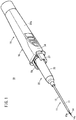
Fig. 1 is a perspective view of a catheter assembly according to a first embodiment. -
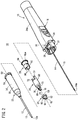
Fig. 2 is an exploded perspective view of the catheter assembly ofFig. 1 . -
Fig. 3 is a side view of an opening member ofFig. 1 . -
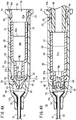
Fig. 4A is a cross-sectional view illustrating a state where the opening member is attached to a catheter hub ofFig. 1 , andFig. 4B is a cross-sectional view illustrating a state where a valve body of the catheter hub ofFig. 4A is opened. -
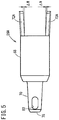
Fig. 5 is a side view of an opening member according to a second embodiment. -
Fig. 6A is a cross-sectional view illustrating a state where the opening member is inserted into a catheter hub according to the second embodiment, andFig. 6B is a cross-sectional view illustrating a state where a valve body of the catheter hub ofFig. 6A is opened. -
Fig. 7A is a side view of an opening member according to a first modification of the second embodiment, andFig. 7B is a view illustrating a side surface and a proximal end surface of an opening member according to a second modification of the second embodiment. -
Fig. 8A is a side view of an opening member according to a third embodiment, andFig. 8B is a plan view of the opening member ofFig. 8A . -
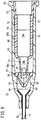
Fig. 9 is a cross-sectional view illustrating a state where the opening member ofFig. 8A is inserted into a catheter hub according to the third embodiment. -
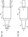
Fig. 10A is a side view of an opening member according to a fourth embodiment, andFig. 10B is a plan view of the opening member ofFig. 10A . -
Fig. 11 is a cross-sectional view illustrating a state where the opening member ofFig. 10A is inserted into a catheter hub according to the fourth embodiment. -
Fig. 12A is a cross-sectional view of a catheter hub according to a fifth embodiment, andFig. 12B is a side view of an opening member according to the fifth embodiment. -
Fig. 13 is a cross-sectional view illustrating a state where the opening member ofFig. 12B is inserted into the catheter hub ofFig. 12A . - Hereinafter, preferred embodiments of the present invention will be described in detail with reference to the accompanying drawings.
- A
catheter assembly 10 according to the present embodiment has acatheter 12 that is inserted to indwell inside a patient's body (living body) as illustrated inFig. 1 , and is used to construct an inlet/outlet for a liquid (a medicinal liquid and blood) during an infusion, a blood transfusion, or the like. Thecatheter 12 is configured, for example, as a peripheral venous catheter. Incidentally, thecatheter 12 may be a catheter longer than the peripheral venous catheter (for example, a central venous catheter, a PICC, a mid-line catheter, and the like). In addition, thecatheter 12 is not limited to a venous catheter, and may be configured as an arterial catheter such as a peripheral arterial catheter. - As illustrated in the drawing, the
catheter assembly 10 has anoperating member 18 formed of aninner needle 14 and aneedle hub 16 fixed to a proximal end of theinner needle 14. Further, thecatheter assembly 10 has acatheter indwelling body 22 formed of the above-describedcatheter 12 and acatheter hub 20 fixed to a proximal end of thecatheter 12. - The
catheter assembly 10 is assembled with theoperating member 18 from the proximal side of thecatheter indwelling body 22 in an initial state (product provided state) before use, thereby forming amulti-structure needle 11 through which theinner needle 14 is inserted in thecatheter 12. In themulti-structure needle 11, theneedle tip 14a of theinner needle 14 protrudes, and theinner needle 14 and thecatheter 12 can be integrally punctured the living body. Further, avalve body 24, anopening member 26, and afixing member 28 are housed inside thecatheter hub 20 as illustrated inFig. 2 . - When using the
catheter assembly 10 illustrated inFig. 1 , a user, such as a doctor and a nurse, grips and operates theneedle hub 16 in the initial state to puncture themulti-structure needle 11 into the patient's body, thereby setting a puncture state where theneedle tip 14a reaches a blood vessel. Further, the user inserts thecatheter 12 into the blood vessel by advancing thecatheter 12 relative to theinner needle 14 while maintaining the puncture state. Thereafter, the user removes theinner needle 14 from thecatheter 12 such that thecatheter 12 indwells in the blood vessel. A connector 95 (seeFig. 4B ) or the like is connected to thecatheter 12 indwelling in the blood vessel via thecatheter hub 20. Through thisconnector 95, treatment such as administration of a medicinal liquid or blood and blood sampling is performed. Hereinafter, each configuration of thecatheter assembly 10 will be further described. - As illustrated in
Fig. 2 , theinner needle 14 of the catheter assembly 10 (the operating member 18) is configured as a hollow tube having rigidity capable of puncturing a skin of a living body, and has thesharp needle tip 14a at a distal end thereof. Inside theinner needle 14, ahollow portion 15 is provided along the axial direction. Theneedle tip 14a is formed at a distal end of a blade surface inclined at a predetermined angle with respect to the axial direction of theinner needle 14. A groove or a hole communicating with thehollow portion 15 for flashback that guides blood to the proximal side at the time of puncturing a blood vessel may be formed on an outer peripheral surface of theinner needle 14. - Examples of a constituent material of the
inner needle 14 include a metal material such as stainless steel, aluminum or an aluminum alloy, and titanium or a titanium alloy, a hard resin, ceramics, and the like. Theinner needle 14 is firmly fixed to theneedle hub 16 by a fixing means such as fusion, adhesion, and fitting. - The
needle hub 16 forms a grip portion to be gripped by the user in the initial state where thecatheter indwelling body 22 and the operatingmember 18 are assembled. Theneedle hub 16 includes a hubmain body 34 that is directly gripped by the user, and an innerneedle support portion 36 that is integrally molded at a distal end of the hubmain body 34. - The hub
main body 34 is formed to have a shape and a size that allow themulti-structure needle 11 to be stably operated. The hubmain body 34 is formed in a cylindrical shape on the proximal side and is gradually deformed into an elliptical shape toward the distal side, and has acavity portion 34a formed inside. - The inner
needle support portion 36 is formed in a columnar shape protruding from the hubmain body 34 in the distal direction, and holds a proximal portion of theinner needle 14 at the central portion thereof. A pair ofarms 38 to hold aflange 54 of thecatheter hub 20 are provided on both side portions of the innerneedle support portion 36. Thearm 38 is housed in anarm accommodating portion 37 that restricts the outward displacement of thearm 38. Thearm accommodating portion 37 is assembled so as to be capable of moving backward with respect to thearm 38, and is configured such that a distal end of thearm 38 is open outward to release the engagement with thecatheter hub 20 when thearm accommodating portion 37 retracts from thearm 38. - A constituent material of the
needle hub 16 is not particularly limited, but a thermoplastic resin, such as polypropylene, polycarbonate, polyamide, polysulfone, polyarylate, and a methacrylate-butylene-styrene copolymer can be applied. - On the other hand, the
catheter 12 is formed as a flexible hollow body in which alumen 13 is formed inside. An outer diameter of thecatheter 12 and thelumen 13 are formed in a perfect circular shape in cross-sectional view orthogonal to the axial direction, and extend along the axial direction of thecatheter 12. Thelumen 13 communicates with adistal opening 13a formed at a distal end of thecatheter 12 and aproximal opening 13b (seeFig. 4A ) formed at a proximal end of thecatheter 12. - A material forming the
catheter 12 is not particularly limited, but a transparent soft resin material may be applied. For example, a fluorine-based resin such as polytetrafluoroethylene (PTFE), an ethylene-tetrafluoroethylene copolymer (ETFE), and a perfluoroalkoxy fluorine resin (PFA), an olefin-based resin such as polyethylene and polypropylene or a mixture thereof, polyurethane, polyester, polyamide, a polyether nylon resin, a mixture of the olefin-based resin and an ethylenevinyl acetate copolymer, and the like may be used. - A length of the
catheter 12 is not particularly limited, and can be appropriately designed according to the application, various conditions, and the like, and is set to, for example, about 14 to 500 mm. The proximal end of thecatheter 12 is inserted and fixed inside thecatheter hub 20. - The
catheter hub 20 is arranged on a patient's skin in a state where thecatheter 12 has been inserted into the patient's blood vessel, and is fixed onto the skin with a tape or the like, thereby being placed together with thecatheter 12. A material forming thecatheter hub 20 is not particularly limited, but, for example, the materials exemplified in theneedle hub 16 can be appropriately adopted. - The
catheter hub 20 is formed in a tubular shape tapered in a distal direction. Aninternal space 50 is provided inside thecatheter hub 20, and theinternal space 50 communicates with theproximal opening 13b (seeFig. 4A ) of thelumen 13 of thecatheter 12 on the distal side. Further, the proximal side of theinternal space 50 communicates with aproximal opening portion 52 of thecatheter hub 20. Thevalve body 24, the openingmember 26, and the fixingmember 28 are housed in theinternal space 50. Further, theflange 54 extending along the circumferential direction is provided on an outer peripheral surface of thecatheter hub 20 on the proximal side. - The
catheter 12 and thecatheter hub 20 are fixed by a fixing means such as caulking, fusion, adhesion, and fitting. Incidentally, acaulking pin 56 is inserted, and thecatheter 12 is sandwiched between theinner wall 20a of thecatheter hub 20 and thecaulking pin 56 to fix thecatheter 12 in the example ofFig. 4A . - As illustrated in
Fig. 2 , thevalve body 24 is arranged in theinternal space 50 of thecatheter hub 20, and forms a hemostatic valve that inhibits blood, which flows from thelumen 13 of thecatheter 12 into theinternal space 50, from leaking to theproximal opening portion 52. Although not particularly limited, thevalve body 24 can be configured as a duckbill valve. Further, thevalve body 24 may be a disc valve. - For example, the
valve body 24 has anannular portion 58 fixed to theinner wall 20a of thecatheter hub 20 and a valvemain body 60 protruding from theannular portion 58 in the distal direction. As illustrated inFig. 4A , theinner wall 20a of thecatheter hub 20 is provided with a steppedportion 21a protruding inward and a lockingconvex portion 21b provided to be apart on the proximal side of the steppedportion 21a in order to attach thevalve body 24. Thevalve body 24 is immovably fixed as theannular portion 58 is sandwiched between the steppedportion 21a and the lockingconvex portion 21b. - The valve
main body 60 is formed in a cylindrical shape on theannular portion 58 side and is formed in a tubular shape having a pair ofinclined portions 62 that approach each other in the distal direction. Avalve space 25 that narrows in the distal direction is formed inside thevalve body 24. - Further, an
end surface 63 extending in the width direction is formed at distal ends of the pair ofinclined portions 62. Aslit 64 is formed in theend surface 63. Theslit 64 extends along the longitudinal direction of theend surface 63, extends between the pair ofinclined portions 62 to a side portion of the valvemain body 60, and extends to a distal end of theannular portion 58. Theslit 64 allows the insertion of theinner needle 14 and is restored by an elastic restoring force after theinner needle 14 is removed. - Further, the pair of
inclined portions 62 of the valvemain body 60 are configured to be greatly separated from each other to open theslit 64 as illustrated inFig. 4B along with the insertion of the openingmember 26 arranged on the proximal side. As a result, a force with which the openingmember 26 inserts thevalve body 24 can be reduced. Further, since thevalve body 24 includes the pair ofinclined portions 62 and theslit 64, a force of pushing the openingmember 26 back to the proximal side is weakened, so that it is easy to maintain an open state of thevalve body 24 achieved by the openingmember 26. - As illustrated in
Fig. 3 , the openingmember 26 includes acylindrical barrel portion 68, aneck portion 70 which is connected to a distal end of thebarrel portion 68, has a smaller diameter than thebarrel portion 68, and protrudes in the distal direction, and a pair offoot portions 72 which are connected to a proximal end of thebarrel portion 68 and protrude in the proximal direction. As illustrated inFig. 4A , aspace portion 74 is formed inside thebarrel portion 68 and theneck portion 70. - The
barrel portion 68 is formed to have an outer diameter slightly smaller than an inner diameter of theinternal space 50 of thecatheter hub 20, and includes a barrel-portion-side space portion 74a which is a part of thespace portion 74 inside. An outer peripheral surface of thebarrel portion 68 is formed in a circular shape in cross-sectional view orthogonal to the axial direction of the openingmember 26. The barrel-portion-side space portion 74a communicates with aproximal opening 68a provided at a proximal end of thebarrel portion 68. - The
neck portion 70 is formed to have a diameter that can be inserted inside theannular portion 58 of thevalve body 24. As illustrated inFig. 4B , theneck portion 70 is configured to penetrate through theslit 64 of thevalve body 24 to push and widen the pair ofinclined portions 62 and widely open the valvemain body 60 when the openingmember 26 moves in the distal direction. Theneck portion 70 has a width that allows insertion with respect to a proximal-portion-side inlet of thevalve space 25, but a shoulder portion, which is a step between thebarrel portion 68 and theneck portion 70, is wider than the proximal-portion-side inlet of thevalve space 25 so that the shoulder portion abuts on theannular portion 58. Therefore, the movement of the openingmember 26 to the distal side of such an abutment position is restricted. Therefore, a favorable positional relationship that suppresses blood retention between the pair of side holes 80 provided in theneck portion 70 and theslit 64 of thevalve body 24 can be maintained. Incidentally, the shoulder portion has a shape that does not come into contact with the lockingconvex portion 21b, for example, a shape in which an end surface of the shoulder portion is chamfered. - As illustrated in
Fig. 3 , a rib structure is formed on an outer peripheral portion of theneck portion 70 so as to protrude radially outward. The rib structure is formed of a pair of neck ribs 73 (a movement inhibiting mechanism as a contact portion). Incidentally, theneck ribs 73 are not limited to the pair, and one or a plurality ofneck ribs 73 may be arranged, but a case where the pair ofneck ribs 73 are provided will be described here as an example. The pair ofneck ribs 73 are arranged so as to oppose each other while being separated by 180° in the circumferential direction. Theneck rib 73 is formed to have a predetermined length along the axial direction from a boundary portion between thebarrel portion 68 and theneck portion 70 to the middle of the axially distal side of theneck portion 70. As illustrated inFig. 4A , theneck rib 73 is formed so as to project outward from an inner diameter of theannular portion 58, and theneck rib 73 is configured to abut on a proximal portion of theannular portion 58. Theneck rib 73 is configured to restrict the movement of the openingmember 26 in the distal direction by being caught by theannular portion 58 when an impact load due to a fall or the like acts on the openingmember 26. The rib structure can also be called a restriction means for restricting the movement of the openingmember 26 in the distal direction. - An axial length of the
neck rib 73 is set such that a distal end of theneck portion 70 is separated from the valvemain body 60 when theneck rib 73 abuts on the proximal portion of theannular portion 58. Incidentally, theneck rib 73 is formed in a size that enters an inner diameter portion of theannular portion 58 and does not interfere with the movement of the openingmember 26 in the distal direction when the openingmember 26 is pressed to the distal side with a force equal to or greater than a predetermined load. - The opening
member 26 is arranged closer to the proximal side than the valvemain body 60 of thevalve body 24 in an initial state. In this state, theneck portion 70 at the distal end of the openingmember 26 is configured to be maintained in the state of being separated from the valvemain body 60 and to prevent the opening of thevalve body 24. - As illustrated in
Fig. 4A , a neck-portion-side space 74b, which is a part of thespace portion 74, is formed inside theneck portion 70. The neck-portion-side space 74b extends along the axial direction of theneck portion 70 and has a distal end communicating with adistal opening 78 formed at the distal end of theneck portion 70 and a proximal end communicating with the barrel-portion-side space portion 74a. Further, the distal side of theneck portion 70 is formed in a tapered shape whose diameter gradually decreases in the distal direction of the openingmember 26. - The pair of side holes 80 are formed in the tapered portion of the distal end of the
neck portion 70. The pair of side holes 80 oppose each other with the neck-portion-side space 74b interposed therebetween. Each of the side holes 80 is provided at a predetermined distance from thedistal opening 78, penetrates theneck portion 70 in the thickness direction, and causes the neck-portion-side space 74b to communicate with the outside of theneck portion 70. - The opening
member 26 is positioned such that theslit 64 of thevalve body 24 and the pair of side holes 80 are at the same phase (circumferential position) in the initial state. With such positioning, each of the side holes 80 is exposed to a site where theslit 64 of thevalve body 24 is open when the openingmember 26 opens the valvemain body 60 along with the insertion of theconnector 95 as illustrated inFig. 4B . That is, the pair of side holes 80 are located closer to the distal side than a part of theslit 64 on the most proximal side in the state where the openingmember 26 opens thevalve body 24. - When the
neck rib 73 of the openingmember 26 abuts on the proximal portion of theannular portion 58, thedistal opening 78 of the openingmember 26 is positioned so as not to come into contact with inner surfaces of the pair ofinclined portions 62 of the valvemain body 60. That is, thedistal opening 78 of the openingmember 26 is located closer to the proximal side than the inner surface portion of theinclined portion 62 located on a path where thedistal opening 78 of the openingmember 26 moves to the distal side. As a result, it is possible to prevent the openingmember 26 from inadvertently opening the valvemain body 60 before use. - As illustrated in
Fig. 3 , the pair offoot portions 72 are provided on the proximal side of thebarrel portion 68 so as to oppose each other. Thefoot portion 72 is formed as a rectangular piece having a predetermined length in the proximal direction. Each of thefoot portions 72 is formed in an arc shape according to an outer diameter shape of thebarrel portion 68 when viewed from the axially proximal side. As illustrated inFig. 4B , a proximal end of thefoot portion 72 protrudes inward from an inner peripheral surface of the fixingmember 28. When theconnector 95 is inserted into thecatheter hub 20, a distal portion of theconnector 95 comes into contact with the proximal end of thefoot portion 72. Therefore, the openingmember 26 moves in the distal direction under a pressing force of theconnector 95. - As illustrated in
Fig. 2 , the fixingmember 28 is an inner member that prevents detachment of the openingmember 26 arranged in theinternal space 50 of thecatheter hub 20. The fixingmember 28 exerts a function of restricting the rotation of the openingmember 26 in the circumferential direction with respect to thecatheter hub 20. The fixingmember 28 is fixed to thecatheter hub 20 by fitting the openingmember 26 into theinner wall 20a of thecatheter hub 20 in a state of being housed in theinternal space 50. Incidentally, a fixing means between thecatheter hub 20 and the fixingmember 28 is not particularly limited, and may be fitting, adhesion, fusion, or the like. - The fixing
member 28 includes a fixedtubular body 82 having a through-hole 82a, and an annularconvex portion 84 provided at a proximal end of the fixedtubular body 82. The proximal end of the fixedtubular body 82 forms theproximal opening portion 52 of thecatheter hub 20. The fixedtubular body 82 is formed with a pair ofnotch portions 86 in which the pair offoot portions 72 of the openingmember 26 are inserted. The pair ofnotch portions 86 are provided at opposing positions with the through-hole 82a interposed therebetween, and extend in the proximal direction from a distal end of the fixedtubular body 82. The annularconvex portion 84 is arranged in atubular groove portion 54a inside theflange 54 formed at the proximal end of thecatheter hub 20 to inhibit the displacement of the fixingmember 28 in the distal direction as illustrated inFig. 4A . - The
catheter assembly 10 according to the present embodiment is configured as described above, and effects thereof will be described hereinafter. - The
catheter assembly 10 is used in a case of constructing the inlet/outlet for the infusion, the blood transfusion, the blood sampling, or the like to the patient. The user grips and operates theneedle hub 16 of thecatheter assembly 10 in the initial state illustrated inFig. 1 to puncture the patient with themulti-structure needle 11. - When the
needle tip 14a of theinner needle 14 reaches the blood vessel, blood flows into thelumen 13 of thecatheter 12. As a result, the user can visually recognize a flashback of blood and confirm that thelumen 13 has secured the blood vessel. When flowing inside thelumen 13 of thecatheter 12 in the proximal direction, the blood flows into theinternal space 50 of thecatheter hub 20 from theproximal opening 13b (seeFig. 4A ). In theinternal space 50, thevalve body 24 is inserted through theinner needle 14, but seals the periphery of theinner needle 14, so that the outflow of blood to a site closer to the proximal side than thevalve body 24 can be suppressed. - In the puncture state, the user advances the
catheter 12 relative to theinner needle 14 and inserts thecatheter 12 into the blood vessel. At a stage where thecatheter 12 is inserted into the blood vessel to some extent, the operatingmember 18 is retracted with respect to thecatheter indwelling body 22. As a result, theinner needle 14 is detached from thecatheter 12. - In the
catheter hub 20, when theneedle tip 14a of theinner needle 14 is pulled out from thevalve body 24, the valvemain body 60 is elastically restored, and theslit 64 is closed. As a result, blood is blocked by thevalve body 24, and blood is inhibited from flowing out to the proximal side. Further, if theinner needle 14 and theneedle hub 16 are retracted, theinner needle 14 is detached from theproximal opening 13b of thecatheter hub 20. That is, the inside of thecatheter hub 20 is in the state illustrated inFig. 4A . Thecatheter indwelling body 22 in this state is set to indwell in the patient. - As illustrated in
Fig. 4A , the openingmember 26 is inhibited from moving toward the distal side in the indwelling state of thecatheter indwelling body 22 as theneck rib 73 of the openingmember 26 is caught by theannular portion 58. As a result, it is possible to prevent unintentional opening of thevalve body 24. - In the indwelling state of the
catheter indwelling body 22, the user can insert theconnector 95, which communicates with a tube of an infusion line, a syringe, or the like, into theinternal space 50 through the proximal opening of thecatheter hub 20 as illustrated inFig. 4B . Theconnector 95 is inserted inside the fixingmember 28. The proximal end of thefoot portion 72 of the openingmember 26 protrudes inward from the fixingmember 28, and thus, comes into contact with a distal end of theconnector 95. As a result, the user can push the openingmember 26 in the distal direction at the time of connecting theconnector 95. When the openingmember 26 is pushed in, the pair offoot portions 72 are guided by the notch portions 86 (seeFig. 2 ) of the fixingmember 28 to move, and thus, move forward without rotating in the circumferential direction. - As the opening
member 26 is pressed via theconnector 95, theneck rib 73 moves inside thevalve body 24 while pushing and widening theannular portion 58. Then, theneck portion 70 opens theslit 64 by separating the pair ofinclined portions 62 from each other as illustrated inFig. 4B . In an insertion completion state where theconnector 95 is fitted to thecatheter hub 20, theneck portion 70 of the openingmember 26 greatly separates the pair ofinclined portions 62. Then, the pair of side holes 80 of theneck portion 70 are arranged in a portion where theslit 64 of thevalve body 24 is widely opened. - The
catheter assembly 10 of the present embodiment has the following effects. - The
catheter assembly 10 of the present embodiment includes: theinner needle 14 with which the living body is punctured; thecatheter 12 through which theinner needle 14 is inserted; thecatheter hub 20 provided at the proximal end of thecatheter 12; thevalve body 24 provided in theinternal space 50 of thecatheter hub 20; and the openingmember 26 which has thecylindrical barrel portion 68, theneck portion 70 extending from the distal end of thebarrel portion 68 while being reduced in diameter, and thefoot portion 72 extending to the proximal side of thebarrel portion 68, is arranged on the proximal side of thevalve body 24, and moves to the distal side along theinternal space 50 of thecatheter hub 20 to open thevalve body 24 by theneck portion 70; and the movement inhibiting mechanism that generates the resistance force against the movement of the openingmember 26 to the distal side. The movement inhibiting mechanism includes the contact portion that generates the frictional force against thecatheter hub 20 or thevalve body 24. - According to the
catheter assembly 10, the contact portion can prevent the openingmember 26 from moving to the distal side due to an impact or the like, and thus, thevalve body 24 can be prevented from being opened unintentionally. - In the above-described
catheter assembly 10, the contact portion may include theneck rib 73 that protrudes toward the outer peripheral side of theneck portion 70 and abuts on thevalve body 24. With this configuration, theneck rib 73 restricts the movement of the openingmember 26 to the distal end, so that thevalve body 24 can be prevented from being open unintentionally. Further, regarding details of theneck rib 73, for example, both sides of a rib width can be reduced in diameter in a tapered shape toward the outer periphery to appropriately adjust a frictional force and push the openingmember 26 in the distal direction. Further, corners of the contact portion and the side surface are preferably rounded. - The opening
member 26 has been described with the embodiment in which thecylindrical barrel portion 68, theneck portion 70 extending from the distal end of thebarrel portion 68 while being reduced in diameter, and thefoot portion 72 extending to the proximal side of thebarrel portion 68, but may adopt a mode of being formed of thecylindrical barrel portion 68 and theneck portion 70 extending from the distal end of thebarrel portion 68. Even in such a mode, the above-described effects can be achieved by providing a movement inhibiting mechanism that generates a resistance force against the movement of the openingmember 26 to the distal side and providing the movement inhibiting mechanism with a contact portion that generates a frictional force against thecatheter hub 20 or thevalve body 24. - Hereinafter, other embodiments of the present invention will be described. Incidentally, an element having the same configuration or the same function as that of the first embodiment will be denoted by the same reference sign, and the detailed description thereof will be omitted in the following description.
- As illustrated in
Fig. 5 , an openingmember 26A according to a second embodiment is not provided with the neck rib 73 (seeFig. 3 ) on theneck portion 70. Instead, a pair offoot portion 72A are formed to gradually widen outward to the proximal side. Thefoot portion 72A is formed so as to be inclined to be widen outward by a width ΔW at a proximal portion. A distance between outer surfaces of the pair offoot portions 72A is larger than an inner diameter of theinner wall 20a of thecatheter hub 20. - As illustrated in
Fig. 6A , when the openingmember 26A is inserted into theinternal space 50 of thecatheter hub 20, thefoot portion 72A is elastically deformed inward. At that time, thefoot portion 72A exerts a frictional force by pressing and abutting on theinner wall 20a of thecatheter hub 20 due to an elastic restoring force, and restricts the movement of the openingmember 26A in the distal direction. That is, thefoot portion 72A forms a movement inhibiting mechanism that generates a resistance force against the movement of the openingmember 26A to the distal side in the present embodiment. - As illustrated in
Fig. 6B , the openingmember 26A of the present embodiment moves in the distal direction to open thevalve body 24 along with the insertion of theconnector 95. Incidentally, a frictional force generated on the outer surface of thefoot portion 72A is appropriately set within a range that does not make it difficult to attach theconnector 95 to thecatheter hub 20. The frictional force generated on the outer surface of thefoot portion 72A can be appropriately adjusted by the inclination of thefoot portion 72A and the rigidity of thefoot portion 72A. - As illustrated in
Fig. 7A , an openingmember 26B according to the present modification includes afoot portion 72B whose wall thickness increases toward a proximal portion. Thefoot portion 72B is formed such that a wall thickness T1 gradually increases to a wall thickness T2 from the distal side to the proximal side. An inner peripheral surface of thefoot portion 72B extends in a direction parallel to the axial direction of the openingmember 26B, and an outer peripheral surface of thefoot portion 72B is formed so as to gradually widen outward toward the proximal portion. - According to the opening
member 26B provided with such afoot portion 72B, it is possible to obtain the same effects as those of the openingmember 26A formed with thefoot portion 72A widening outward. - As illustrated in
Fig. 7B , an openingmember 26C according to the present modification includes afoot portion 72C whose wall thickness gradually increases toward the proximal side. Thefoot portion 72C of the openingmember 26C of the present modification is similar to thefoot portion 72B of the openingmember 26B ofFig. 7A in terms of the wall thickness. However, anotch portion 72a is formed by cutting out a part of thefoot portion 72C in a groove shape. As illustrated in the drawing, each of thefoot portions 72C is formed with a pair of thenotch portions 72a so as to form a T shape when viewed from the proximal side. With this configuration, the rigidity of thefoot portion 72C can be adjusted within an appropriate range to adjust a frictional force. - As illustrated in
Fig. 8A , anopening member 26D according to the present embodiment has a thin rib structure 75 (protruding structure) formed in a part from the outer circumference of thebarrel portion 68 to the outer circumference of thefoot portion 72. A pair of therib structures 75 are provided to correspond to thefoot portions 72. As illustrated inFig. 8B , therib structure 75 is formed so as to extend to be straight (linearly) in the axial direction from a proximal portion of thefoot portion 72 to a vicinity of a distal end of thebarrel portion 68. Further, therib structure 75 may be provided only in thebarrel portion 68. - Incidentally, the
rib structure 75 has a structure in which the thickness of thefoot portion 72 is gradually increased toward the proximal side, so that the same effects as those of the second embodiment can be obtained. - As illustrated in
Fig. 9 , therib structure 75 protruding outward from thebarrel portion 68 and thefoot portion 72 abuts on theinner wall 20a to exert a frictional force when the openingmember 26D is inserted into theinternal space 50 of thecatheter hub 20. As a result, the movement of the openingmember 26D in the distal direction due to an impact or the like is restricted. That is, therib structure 75 forms a movement inhibiting mechanism that generates a resistance force against the movement of the openingmember 26D to the distal side in the present embodiment. - Incidentally, the frictional force of the
rib structure 75 is appropriately set within a range that does not interfere with the connection of theconnector 95 to thecatheter hub 20. As a result, the openingmember 26D can be pressed by theconnector 95 to open thevalve body 24. - An opening
member 26E according to the present embodiment is provided with an island-shaped convex portion 77 (protruding structure) formed so as to protrude outward more than an outer diameter of thebarrel portion 68 at a boundary portion between thebarrel portion 68 and thefoot portion 72 as illustrated inFigs. 10A and 10B . A pair of theconvex portions 77 are provided similarly thefoot portions 72, but the present invention is not limited thereto, and only one or a plurality ofconvex portions 77 may be provided. Further, an installation position of theconvex portion 77 is not limited to the boundary portion between thebarrel portion 68 and thefoot portion 72, and may be provided at an arbitrary position on the outer circumference of thebarrel portion 68 or thefoot portion 72. Further, a shape of theconvex portion 77 is not limited to the island shape, and may be formed in a circular ring shape along the outer circumference of thebarrel portion 68, for example. - As illustrated in
Fig. 11 , aconcave portion 23 to receive theconvex portion 77 is formed on theinner wall 20a in a portion corresponding to theconvex portion 77 of the openingmember 26E in acatheter hub 20A of the present embodiment. When the openingmember 26E is inserted into theinternal space 50 of thecatheter hub 20A, theconvex portion 77 of the openingmember 26E fits into theconcave portion 23 of thecatheter hub 20, so that a frictional force that restricts the movement of the openingmember 26E in the distal direction is exerted. That is, theconvex portion 77 of the openingmember 26E and theconcave portion 23 of thecatheter hub 20 form a movement inhibiting mechanism that generates a resistance force against the movement of the openingmember 26E to the distal side in the present embodiment. - Incidentally, the frictional force generated by the
convex portion 77 and theconcave portion 23 is appropriately set within a range that does not interfere with the connection of theconnector 95 to thecatheter hub 20A. As a result, the openingmember 26E can be pressed by theconnector 95 to open thevalve body 24. Further, the movement inhibiting mechanism may be formed of only the convex portion. - As illustrated in
Fig. 12B , an openingmember 26F according to the present embodiment is provided with an island-shapedconcave portion 79 which is formed at a boundary portion between thebarrel portion 68 and thefoot portion 72 to be recessed inward from an outer diameter of thebarrel portion 68. A pair of theconcave portions 79 are provided similarly thefoot portions 72, but the present invention is not limited thereto, and only one or a plurality ofconcave portions 79 may be provided. Further, an installation position of theconcave portion 79 is not limited to the boundary portion between thebarrel portion 68 and thefoot portion 72, and may be provided at an arbitrary position on the outer circumference of thebarrel portion 68 or thefoot portion 72. Further, a shape of theconcave portion 79 is not limited to the island shape, and may be formed in a circular ring shape along the outer circumference of thebarrel portion 68, for example. - As illustrated in
Fig. 12A , aconvex portion 27 protruding inward is formed on theinner wall 20a in a portion corresponding to theconcave portion 79 of the openingmember 26F in acatheter hub 20B of the present embodiment. A shape of theconvex portion 27 is formed in an island shape according to the shape of theconcave portion 79. Incidentally, when theconcave portion 79 is formed in a circular ring shape, theconvex portion 27 may be formed in a circular ring shape. - As illustrated in
Fig. 13 , when the openingmember 26F is inserted into theinternal space 50 of thecatheter hub 20B, theconcave portion 79 of the openingmember 26F fits into theconvex portion 27 of thecatheter hub 20B, so that a frictional force that restricts the movement of the openingmember 26F in the distal direction is exerted. That is, theconcave portion 79 of the openingmember 26F and theconvex portion 27 of thecatheter hub 20B form a movement inhibiting mechanism that generates a resistance force against the movement of the openingmember 26F to the distal side in the present embodiment. - Incidentally, the frictional force generated by the
concave portion 79 and theconvex portion 27 is appropriately set within a range that does not interfere with the connection of theconnector 95 to thecatheter hub 20B. As a result, the openingmember 26F can be pressed by theconnector 95 to open thevalve body 24. Further, the movement inhibiting mechanism may be formed of only the convex portion. - Although the present invention has been described with the preferred embodiments as above, it is obvious that the present invention is not limited to the above-described embodiments, and various modifications can be made within a scope not departing from a gist of the present invention.
Claims (10)
- A catheter assembly comprising:an inner needle with which a living body is punctured;a catheter through which the inner needle is inserted;a catheter hub provided at a proximal end of the catheter;a valve body provided in an internal space of the catheter hub;an opening member which has a cylindrical barrel portion, a neck portion extending from a distal end of the barrel portion while being reduced in diameter, and a foot portion extending to a proximal side of the barrel portion, is arranged on a proximal side of the valve body, and moves to a distal side along the internal space of the catheter hub to open the valve body by the neck portion; anda movement inhibiting mechanism that generates a resistance force against the movement of the opening member to the distal side,wherein the movement inhibiting mechanism includes a contact portion that generates a frictional force against the catheter hub or the valve body.
- The catheter assembly according to claim 1, wherein the contact portion has a rib structure that protrudes to an outer peripheral side of the neck portion and abuts on the valve body.
- The catheter assembly according to claim 1, wherein the contact portion is configured of the foot portion formed so as widen outward more than an outer diameter of the barrel portion, and generates the frictional force when the foot portion abuts on the catheter hub.
- The catheter assembly according to claim 1, wherein the contact portion has a protruding structure formed so as to protrude outward from an outer diameter of the barrel portion, and generates the frictional force when the protruding structure abuts on the catheter hub.
- The catheter assembly according to claim 4, wherein the protruding structure is formed of a linear rib structure extending in parallel to an outer peripheral portion of the barrel portion in an axial direction.
- The catheter assembly according to claim 4, wherein the protruding structure is formed of a convex portion provided on the barrel portion or the foot portion.
- The catheter assembly according to claim 6, wherein a concave portion is formed in a portion corresponding to the convex portion on an inner wall of the catheter hub.
- The catheter assembly according to claim 6, wherein the convex portion is provided on a boundary between the barrel portion and the foot portion.
- The catheter assembly according to claim 1, wherein the contact portion is formed of a convex portion formed so as to protrude from an inner wall of the catheter hub.
- The catheter assembly according to claim 9, wherein an outer peripheral portion of the opening member is provided with a concave portion in a portion corresponding to the convex portion, and the convex portion is fitted into the concave portion to generate the frictional force.
Applications Claiming Priority (2)
| Application Number | Priority Date | Filing Date | Title |
|---|---|---|---|
| JP2019063152 | 2019-03-28 | ||
| PCT/JP2020/010601 WO2020195848A1 (en) | 2019-03-28 | 2020-03-11 | Catheter assembly |
Publications (2)
| Publication Number | Publication Date |
|---|---|
| EP3932460A1 true EP3932460A1 (en) | 2022-01-05 |
| EP3932460A4 EP3932460A4 (en) | 2022-05-18 |
Family
ID=72610492
Family Applications (1)
| Application Number | Title | Priority Date | Filing Date |
|---|---|---|---|
| EP20777837.4A Pending EP3932460A4 (en) | 2019-03-28 | 2020-03-11 | CATHETER ASSEMBLY |
Country Status (5)
| Country | Link |
|---|---|
| US (1) | US12508402B2 (en) |
| EP (1) | EP3932460A4 (en) |
| JP (2) | JP7387717B2 (en) |
| CN (1) | CN113365688B (en) |
| WO (1) | WO2020195848A1 (en) |
Cited By (1)
| Publication number | Priority date | Publication date | Assignee | Title |
|---|---|---|---|---|
| EP3888730A4 (en) * | 2018-12-04 | 2022-06-15 | TERUMO Kabushiki Kaisha | CATHETER ASSEMBLY AND LINEAR INDOOR BODY |
Families Citing this family (7)
| Publication number | Priority date | Publication date | Assignee | Title |
|---|---|---|---|---|
| WO2018125845A1 (en) | 2016-12-27 | 2018-07-05 | Vasonics, Llc | Catheter housing |
| WO2019065943A1 (en) | 2017-09-29 | 2019-04-04 | テルモ株式会社 | Catheter assembly and medical valve |
| JP7387717B2 (en) | 2019-03-28 | 2023-11-28 | テルモ株式会社 | catheter assembly |
| EP3995530B1 (en) | 2019-09-27 | 2025-05-28 | LG Chem, Ltd. | A method of preparing polymer microparticles, polymer microparticles, medical composition, cosmetic composition, medical articles, and cosmetic articles using the same |
| AU2021245668A1 (en) * | 2020-03-30 | 2022-12-01 | Nipro Corporation | Indwelling needle |
| US11992645B2 (en) | 2022-02-10 | 2024-05-28 | St. Jude Medical, Cardiology Division, Inc. | Integrated hemostasis bypass valve |
| JP2025041996A (en) * | 2022-02-25 | 2025-03-27 | テルモ株式会社 | Catheter Assembly |
Family Cites Families (233)
| Publication number | Priority date | Publication date | Assignee | Title |
|---|---|---|---|---|
| JPH03167575A (en) | 1989-11-27 | 1991-07-19 | Mita Ind Co Ltd | Developing device |
| JPH06147186A (en) | 1992-10-30 | 1994-05-27 | Hitachi Koki Co Ltd | Vacuum pump |
| US6117108A (en) | 1997-08-20 | 2000-09-12 | Braun Melsungen Ag | Spring clip safety IV catheter |
| JP4996015B2 (en) | 2001-03-12 | 2012-08-08 | メディキット株式会社 | Indwelling catheter |
| JP3808806B2 (en) | 2002-06-26 | 2006-08-16 | メディキット株式会社 | Indwelling needle |
| DE20210394U1 (en) | 2002-07-04 | 2002-09-12 | B. Braun Melsungen Ag, 34212 Melsungen | catheter introducer |
| US7694403B2 (en) | 2003-03-25 | 2010-04-13 | Becton, Dickinson And Company | Method of forming IV catheter and needle assembly |
| US7435236B2 (en) | 2003-06-27 | 2008-10-14 | Navilyst Medical, Inc. | Pressure actuated valve with improved biasing member |
| US7470254B2 (en) | 2003-08-18 | 2008-12-30 | Medical Components, Inc. | Needle with sealing valve |
| US8034035B2 (en) | 2004-01-29 | 2011-10-11 | Navilyst Medical, Inc. | Pressure activated safety valve with high flow slit |
| US7469458B1 (en) | 2004-08-11 | 2008-12-30 | Proteckt Catheters, Llc | Method of assembling a catheter with integrated pre-slit cannula diaphragm |
| US8747387B2 (en) | 2005-10-11 | 2014-06-10 | Covidien Lp | IV catheter with in-line valve and methods related thereto |
| EP1942980A2 (en) | 2005-10-11 | 2008-07-16 | Covidien AG | Iv catheter with in-line valve and methods related thereto |
| WO2007044878A2 (en) | 2005-10-11 | 2007-04-19 | Covidien Ag | Iv catheter with in-line valve and methods related thereto |
| US7731694B2 (en) | 2005-10-24 | 2010-06-08 | Cardiac Pacemakers, Inc. | Hemostasis seal |
| US7670317B2 (en) | 2005-10-25 | 2010-03-02 | Becton, Dickinson And Company | One piece low drag septum |
| JP5216600B2 (en) | 2006-03-01 | 2013-06-19 | ベクトン・ディキンソン・アンド・カンパニー | Controlled flashback for vascular access devices |
| DE202007006190U1 (en) * | 2006-07-31 | 2007-08-23 | B. Braun Melsungen Ag | catheter device |
| US8308691B2 (en) | 2006-11-03 | 2012-11-13 | B. Braun Melsungen Ag | Catheter assembly and components thereof |
| CA2663152C (en) | 2006-09-29 | 2014-12-02 | Tyco Healthcare Group Lp | Surgical fluid transfer apparatus |
| JP4994775B2 (en) | 2006-10-12 | 2012-08-08 | 日本コヴィディエン株式会社 | Needle point protector |
| JP4909097B2 (en) | 2007-01-17 | 2012-04-04 | 日本コヴィディエン株式会社 | Indwelling needle |
| US7806869B2 (en) | 2007-03-29 | 2010-10-05 | Anders Bengt Erik Nilsson | Blood exposure prevention in vascular access devices |
| JP5139518B2 (en) | 2007-05-07 | 2013-02-06 | バスキュラー・パスウェイズ・インコーポレイテッド | Venous catheter insertion device |
| WO2008152849A1 (en) | 2007-06-12 | 2008-12-18 | Terumo Kabushiki Kaisha | Method of producing indwelling needle assembly and indwelling needle assembly |
| FR2918284B1 (en) | 2007-07-02 | 2009-08-28 | Vygon Sa | DEVICE FOR INTRODUCING A CATHETER GUIDE WIRE IN A VESSEL |
| DE602007013746D1 (en) | 2007-08-01 | 2011-05-19 | Tradinco Ab | Peripheral catheter assembly with hemostasis valve |
| US8142446B2 (en) | 2007-09-18 | 2012-03-27 | Sorin Crm S.A.S. | Toolkit for implanting an intracorporeal lead such as for cardiac pacing or sensing |
| WO2009041523A1 (en) | 2007-09-27 | 2009-04-02 | Terumo Kabushiki Kaisha | Valve element and medical instrument |
| JP5372762B2 (en) | 2007-09-27 | 2013-12-18 | テルモ株式会社 | Valve body and medical device |
| CA2901300A1 (en) | 2008-01-14 | 2009-07-23 | I-V Access Technology, Inc. | An apparatus for peripheral vascular access |
| CA2711454C (en) | 2008-03-14 | 2016-11-29 | Medical Components, Inc. | Tearaway introducer sheath with hemostasis valve |
| WO2009123026A1 (en) | 2008-03-31 | 2009-10-08 | テルモ株式会社 | Medical instrument |
| US9101748B2 (en) | 2008-05-08 | 2015-08-11 | Becton, Dickinson And Company | Push-button blood control |
| US8366684B2 (en) | 2008-05-12 | 2013-02-05 | Becton, Dickinson And Company | Intravenous catheter blood control device |
| CN102099075B (en) | 2008-05-22 | 2013-10-02 | 泰尔茂株式会社 | Catheter retaining tool |
| US8574203B2 (en) | 2009-02-11 | 2013-11-05 | Becton, Dickinson And Company | Systems and methods for providing a flushable catheter assembly |
| US8361038B2 (en) | 2009-02-11 | 2013-01-29 | Becton, Dickinson And Company | Systems and methods for providing a flow control valve for a medical device |
| US8388583B2 (en) | 2009-08-20 | 2013-03-05 | Becton, Dickinson And Company | Systems and methods for providing a flushable catheter assembly |
| US8469928B2 (en) * | 2009-02-11 | 2013-06-25 | Becton, Dickinson And Company | Systems and methods for providing a flushable catheter assembly |
| USRE45896E1 (en) | 2009-02-11 | 2016-02-23 | Becton, Dickinson And Company | Systems and methods for providing a catheter assembly |
| US8496623B2 (en) | 2009-03-02 | 2013-07-30 | Becton, Dickinson And Company | Bi-directional cannula feature capture mechanism |
| US8936575B2 (en) | 2009-03-19 | 2015-01-20 | Becton, Dickinson And Company | Cannula-tip shielding mechanism |
| US8317754B2 (en) | 2009-07-06 | 2012-11-27 | AUST Development, LLC | Valves and hubs for tubular devices and methods for making and using them |
| US8512293B2 (en) | 2009-08-13 | 2013-08-20 | AUST Development, LLC | Valves and hubs for tubular medical devices and methods for making and using them |
| EP3266489B1 (en) | 2009-09-22 | 2023-06-21 | Poly Medicure Limited | Needle guard |
| EP2489393A4 (en) | 2009-10-16 | 2013-04-03 | Terumo Corp | Placement needle and placement needle assembly |
| US8267897B2 (en) | 2010-01-06 | 2012-09-18 | W. L. Gore & Associates, Inc. | Center twist hemostatic valve |
| US9486162B2 (en) | 2010-01-08 | 2016-11-08 | Ultrasonix Medical Corporation | Spatial needle guidance system and associated methods |
| US9950139B2 (en) | 2010-05-14 | 2018-04-24 | C. R. Bard, Inc. | Catheter placement device including guidewire and catheter control elements |
| US8932258B2 (en) | 2010-05-14 | 2015-01-13 | C. R. Bard, Inc. | Catheter placement device and method |
| US10384039B2 (en) | 2010-05-14 | 2019-08-20 | C. R. Bard, Inc. | Catheter insertion device including top-mounted advancement components |
| WO2011146772A1 (en) | 2010-05-19 | 2011-11-24 | Tangent Medical Technologies Llc | Safety needle system operable with a medical device |
| US8652104B2 (en) | 2010-06-25 | 2014-02-18 | Smiths Medical Asd, Inc. | Catheter assembly with seal member |
| US9545495B2 (en) | 2010-06-25 | 2017-01-17 | Smiths Medical Asd, Inc. | Catheter assembly with seal member |
| US9192752B2 (en) | 2010-07-05 | 2015-11-24 | AUST Development, LLC | Serial valves and hubs for tubular devices and methods for making and using them |
| US8361020B2 (en) | 2010-07-15 | 2013-01-29 | Becton, Dickinson And Company | Catheter assembly and pierced septum valve |
| US8357119B2 (en) | 2010-07-15 | 2013-01-22 | Becton, Dickinson And Company | Catheter assembly and pierced septum valve |
| SG10201503405SA (en) | 2010-08-05 | 2015-06-29 | Braun Melsungen Ag | Needle safety device and assembly |
| US8864715B2 (en) | 2010-09-08 | 2014-10-21 | Becton, Dickinson And Company | Assembly method for catheter with blood control |
| US8932259B2 (en) | 2010-09-13 | 2015-01-13 | Becton, Dickinson And Company | Catheter assembly |
| WO2012106088A2 (en) | 2011-01-31 | 2012-08-09 | Helm Robert E Jr | Snap-seal sterile intravascular catheter-dressing system |
| US8690833B2 (en) | 2011-01-31 | 2014-04-08 | Vascular Pathways, Inc. | Intravenous catheter and insertion device with reduced blood spatter |
| US9259554B2 (en) | 2011-03-07 | 2016-02-16 | Becton, Dickinson And Company | Systems and methods to compensate for compression forces in an intravascular device |
| US8641675B2 (en) | 2011-03-07 | 2014-02-04 | Becton, Dickinson And Company | Systems and methods for preventing septum damage in an intravascular device |
| JP5253534B2 (en) | 2011-03-15 | 2013-07-31 | メディキット株式会社 | Indwelling catheter |
| US9999746B2 (en) | 2011-03-22 | 2018-06-19 | Angiodynamics, Inc. | High flow catheters |
| SG193635A1 (en) | 2011-03-28 | 2013-11-29 | Terumo Corp | Catheter assembly |
| EP2753375B1 (en) | 2011-09-09 | 2020-11-04 | Nordic Med -com Aktiebolag | Catheter introducer assembly |
| JP6067567B2 (en) | 2011-09-28 | 2017-01-25 | テルモ株式会社 | Catheter assembly |
| WO2013051242A1 (en) | 2011-10-05 | 2013-04-11 | 二プロ株式会社 | Indwelling catheter |
| US9358364B2 (en) | 2011-10-06 | 2016-06-07 | Becton, Dickinson And Company | Activator attachment for blood control catheters |
| US9126012B2 (en) | 2011-10-06 | 2015-09-08 | Becton, Dickinson And Company | Intravenous catheter with duckbill valve |
| US9155864B2 (en) | 2011-10-06 | 2015-10-13 | Becton, Dickinson And Company | Multiple use blood control valve with center and circumferential slits |
| US9155863B2 (en) | 2011-10-06 | 2015-10-13 | Becton, Dickinson And Company | Multiple use stretching and non-penetrating blood control valves |
| US9089671B2 (en) | 2011-10-06 | 2015-07-28 | Becton, Dickinson And Company | Systems and methods for sealing a septum within a catheter device |
| US9155876B2 (en) | 2011-10-06 | 2015-10-13 | Becton, Dickinson And Company | Port valve of a blood control catheter |
| EP2606920A1 (en) | 2011-12-22 | 2013-06-26 | ECP Entwicklungsgesellschaft mbH | Sluice device for inserting a catheter |
| US9052025B2 (en) | 2011-12-23 | 2015-06-09 | Kenneth M. Zinn | Bidirectional duckbill valve apparatus and a method for its use |
| CA2863419A1 (en) | 2012-01-09 | 2013-07-18 | BiO2 Medical, Inc. | Connector hub apparatus for catheter and methods of use |
| US9108021B2 (en) | 2012-02-22 | 2015-08-18 | Becton, Dickinson And Company | Low drag, high pressure septum |
| US9737686B2 (en) | 2012-03-12 | 2017-08-22 | Becton, Dickinson And Company | Catheter adapter port valve |
| US9352119B2 (en) | 2012-05-15 | 2016-05-31 | Becton, Dickinson And Company | Blood control IV catheter with antimicrobial properties |
| US8622967B2 (en) | 2012-05-15 | 2014-01-07 | Becton, Dickinson And Company | Over-the-needle intravenous catheter assembly with integrated intravenous tubing |
| US9579486B2 (en) | 2012-08-22 | 2017-02-28 | Becton, Dickinson And Company | Blood control IV catheter with antimicrobial properties |
| US9272088B2 (en) | 2012-09-13 | 2016-03-01 | Becton, Dickinson And Company | Intravenous catheter inserter |
| US10105085B2 (en) | 2012-11-03 | 2018-10-23 | ProVazo LLC | Directing hub used with vascular blood sampling catheter |
| US9352127B2 (en) | 2012-11-09 | 2016-05-31 | Carefusion 303, Inc. | Closed-system catheter assembly |
| AU2013342123B2 (en) | 2012-11-12 | 2018-08-02 | Icu Medical, Inc. | Medical connector |
| CN105102054B (en) | 2013-01-30 | 2018-04-20 | 血管通路股份有限公司 | Systems and methods for venipuncture and catheter placement |
| US9782568B2 (en) | 2013-02-05 | 2017-10-10 | Vascular Pathways, Inc. | Systems and methods for needle and catheter advancement |
| US9750928B2 (en) | 2013-02-13 | 2017-09-05 | Becton, Dickinson And Company | Blood control IV catheter with stationary septum activator |
| US9327095B2 (en) | 2013-03-11 | 2016-05-03 | Becton, Dickinson And Company | Blood control catheter with antimicrobial needle lube |
| US9750927B2 (en) | 2013-03-11 | 2017-09-05 | Becton, Dickinson And Company | Blood control catheter with antimicrobial needle lube |
| US10357635B2 (en) | 2013-03-12 | 2019-07-23 | Teleflex Medical Incorporated | Catheter insertion device |
| US9381320B2 (en) | 2013-03-18 | 2016-07-05 | Becton, Dickinson And Company | Multiple-use intravenous catheter assembly septum and septum actuator |
| WO2014189677A1 (en) | 2013-05-20 | 2014-11-27 | St. Jude Medical, Cardiology Division, Inc. | Large bore sheath assembly |
| WO2014188509A1 (en) | 2013-05-21 | 2014-11-27 | テルモ株式会社 | Catheter |
| US10500376B2 (en) | 2013-06-07 | 2019-12-10 | Becton, Dickinson And Company | IV catheter having external needle shield and internal blood control septum |
| US9788943B2 (en) | 2013-06-11 | 2017-10-17 | Medtronic, Inc. | Delivery system with inline sheath |
| BR112016000570B1 (en) | 2013-07-11 | 2022-06-14 | Becton, Dickinson And Company | CATHETER DEVICE |
| US9592367B2 (en) | 2013-07-30 | 2017-03-14 | Becton, Dickinson And Company | Blood control catheter valve employing actuator with flexible retention arms |
| US9775972B2 (en) | 2013-07-30 | 2017-10-03 | Becton, Dickinson And Company | Interlocking needle hub and catheter hub actuator to increase rigidity of IV catheter assembly |
| US9456775B2 (en) | 2013-09-06 | 2016-10-04 | Millaghi Medical, Inc. | Passive safety I.V. blood collection catheter |
| CA2927541C (en) | 2013-10-15 | 2021-06-08 | Radux Devices, LLC | Securing a medical device to a valve instrument |
| US9227047B2 (en) | 2013-10-29 | 2016-01-05 | Avent, Inc. | Catheter connector |
| US9919136B2 (en) * | 2013-12-04 | 2018-03-20 | B. Braun Melsungen Ag | Catheter assembly with reusable valve |
| US9974938B2 (en) | 2013-12-05 | 2018-05-22 | Cardiac Pacemakers, Inc. | Cuttable catheter hub with integrated hemostasis valve |
| EP3082933B1 (en) | 2013-12-20 | 2019-06-19 | B. Braun Melsungen AG | Safety needle assemblies and related method |
| US9895525B2 (en) | 2014-01-21 | 2018-02-20 | Becton, Dickinson And Company | Ported catheter adapter with integrated septum actuator retention |
| US9750925B2 (en) | 2014-01-21 | 2017-09-05 | Becton, Dickinson And Company | Ported catheter adapter having combined port and blood control valve with venting |
| EP4035720A1 (en) | 2014-01-21 | 2022-08-03 | Merit Medical Systems, Inc. | Hub assembly for a medical device |
| GB201402149D0 (en) | 2014-02-07 | 2014-03-26 | Lombard Medical Plc | Valve for medical implant delivery system |
| WO2015123689A1 (en) | 2014-02-17 | 2015-08-20 | The Johns Hopkins University | Catheter hub with removable extensions |
| US10052474B2 (en) | 2014-03-18 | 2018-08-21 | I-V Access Technoiogy, Inc. | Intravenous catheter with pressure activated valve |
| US10729890B2 (en) | 2014-04-18 | 2020-08-04 | Becton, Dickinson And Company | Multi-use blood control safety catheter assembly |
| US10668266B2 (en) | 2014-04-23 | 2020-06-02 | Becton, Dickinson And Company | Ported catheter or female luer fitting with antimicrobial septum |
| US9999761B2 (en) | 2014-07-18 | 2018-06-19 | Jumark Properties Llc | Extracorporeal membrane oxygenation cannula hemostatic plug |
| WO2016036468A1 (en) | 2014-09-01 | 2016-03-10 | AUST Development, LLC | Catheter hubs and valves for minimizing embolic potential |
| US20160067391A1 (en) | 2014-09-04 | 2016-03-10 | Prometheus Deltatech Limited | Transcutaneous device for removal of fluid from a body |
| US10321933B1 (en) | 2014-09-24 | 2019-06-18 | MarVenRay, LLC | Apparatus and methods for vascular access |
| EP3218031B1 (en) * | 2014-11-10 | 2024-02-07 | Becton, Dickinson and Company | Safety iv catheter with v-clip interlock and needle tip capture |
| EP3028737A1 (en) | 2014-12-03 | 2016-06-08 | Tradinco AB | Self-sealing catheder valve |
| US10765853B2 (en) | 2014-12-22 | 2020-09-08 | Cook Medicai Technologies LLC | Hemostatic valve system |
| US10265506B2 (en) | 2015-02-02 | 2019-04-23 | Quick Snap Medical Supply, LLC | Vascular access devices and methods |
| JP2018510722A (en) | 2015-04-09 | 2018-04-19 | ヴィグメッド アーベー | Needle tip shield device and catheter hub therefor |
| US10238853B2 (en) | 2015-04-10 | 2019-03-26 | Silk Road Medical, Inc. | Methods and systems for establishing retrograde carotid arterial blood flow |
| MY182202A (en) | 2015-04-17 | 2021-01-18 | Becton Dickinson Co | Needle capture safety interlock for catheter |
| US9937322B2 (en) | 2015-04-23 | 2018-04-10 | Medtronic, Inc. | Assemblies and methods for deflectable shaft catheters |
| DE102015009190A1 (en) | 2015-07-16 | 2017-01-19 | B. Braun Avitum Ag | dialysis cannula |
| EP3552652B2 (en) | 2015-08-18 | 2024-07-03 | B. Braun Melsungen AG | Catheter devices with valves |
| WO2017042825A2 (en) | 2015-09-08 | 2017-03-16 | Neeraj Gupta | Intravenous catheter with a secured mechanism to avoid reverse flow of the blood |
| EP3347083A1 (en) | 2015-09-09 | 2018-07-18 | B. Braun Melsungen AG | Infusion systems, connectors for use with catheter devices, and related methods |
| WO2017044029A1 (en) | 2015-09-10 | 2017-03-16 | Vigmed Ab | Dental syringe and needle tip shielding system for a dental needle |
| US10525237B2 (en) | 2015-10-28 | 2020-01-07 | Becton, Dickinson And Company | Ergonomic IV systems and methods |
| US10463840B2 (en) | 2015-10-28 | 2019-11-05 | Becton, Dickinson And Company | Compliant catheter adapter having self-slitting needle |
| US10549073B2 (en) | 2015-10-28 | 2020-02-04 | Becton, Dickinson And Company | Compliant catheter adapter and compression cap |
| US10729889B2 (en) | 2015-11-13 | 2020-08-04 | B. Braun Melsungen Ag | Needle devices with dual diameter cannula and related methods |
| EP3389739B1 (en) | 2015-12-18 | 2020-10-14 | Heartware, Inc. | Hollow plug |
| US10926063B2 (en) | 2016-02-17 | 2021-02-23 | North American Rescue, Llc | Decompression needle assembly |
| US10675440B2 (en) | 2016-02-18 | 2020-06-09 | Smiths Medical Asd, Inc. | Closed system catheter |
| US10507281B2 (en) | 2016-03-28 | 2019-12-17 | Becton, Dickinson And Company | Cannula capture mechanism |
| US10898223B2 (en) | 2016-03-28 | 2021-01-26 | Becton, Dickinson And Company | Multi-diameter cannula |
| US10159820B2 (en) | 2016-03-30 | 2018-12-25 | Covidien Lp | Anatomical structure access |
| US11213656B2 (en) | 2016-04-15 | 2022-01-04 | Becton, Dickinson And Company | Medical device with anti-rotation push tab |
| WO2017201369A1 (en) | 2016-05-20 | 2017-11-23 | Smiths Medical Asd, Inc. | Needle assembly with flexible catheter nose for diagnostic sampling of fluid |
| EP3284507B1 (en) | 2016-08-19 | 2023-12-13 | Roche Diabetes Care GmbH | Cannula unit |
| CN109715093B (en) | 2016-09-12 | 2020-11-06 | C·R·巴德股份有限公司 | Blood Control for Catheterization Devices |
| US10238852B2 (en) | 2016-10-05 | 2019-03-26 | Becton, Dickinson And Company | Septum housing |
| US20190269886A1 (en) | 2016-10-31 | 2019-09-05 | Becton, Dickinson And Company | Medical device with reduced occlusion |
| EP3538191A1 (en) | 2016-11-09 | 2019-09-18 | Boston Scientific Limited | Hemostasis valve design for introducer sheath |
| CN110446524B (en) | 2016-11-09 | 2021-10-26 | 波士顿科学有限公司 | Low pressure seal design for hemostatic valves |
| CN110582322B (en) | 2017-01-12 | 2022-07-01 | 静脉注射通路科技公司 | Conduit valve |
| JP7084324B2 (en) | 2017-02-10 | 2022-06-14 | テルモ株式会社 | Medical long body and medical long body set |
| WO2018156148A1 (en) | 2017-02-24 | 2018-08-30 | Becton, Dickinson And Company | Catheter assembly |
| US11400260B2 (en) | 2017-03-01 | 2022-08-02 | C. R. Bard, Inc. | Catheter insertion device |
| CA3053800C (en) | 2017-03-06 | 2020-05-05 | Smiths Medical Asd, Inc. | Blood containment for iv catheter |
| EP3573695A4 (en) | 2017-03-06 | 2020-10-28 | Smiths Medical ASD, Inc. | IV CATHETER WITH VEIN ENTRY INDICATOR |
| SG10201701920QA (en) | 2017-03-09 | 2018-10-30 | Becton Dickinson Co | Intravenous catheter assembly with cannula safety mechanism |
| US10603446B2 (en) | 2017-04-03 | 2020-03-31 | Becton, Dickinson And Company | IV catheter with integral extension set and a spring powered needle safety |
| US11116936B2 (en) | 2017-04-07 | 2021-09-14 | Becton, Dickinson And Company | Low-profile extension for a catheter assembly |
| EP3398646B1 (en) | 2017-05-05 | 2019-10-09 | Greatbatch Ltd. | Medical device with hemostatic valve |
| US11529474B2 (en) | 2017-05-08 | 2022-12-20 | Nipro Corporation | Valved needle assembly |
| US10512755B2 (en) | 2017-06-08 | 2019-12-24 | Becton, Dickinson And Company | Septum securement |
| WO2018224637A1 (en) | 2017-06-09 | 2018-12-13 | B. Braun Melsungen Ag | Adhesive encased protective caps for needle devices and related methods |
| US11147957B2 (en) | 2017-07-19 | 2021-10-19 | Becton, Dickinson And Company | Systems and methods to improve instrument guidance within an intravenous catheter assembly |
| US10426929B2 (en) | 2017-07-19 | 2019-10-01 | Becton, Dickinson And Company | Integrated peripheral intra-venous catheter with improved extension tube port probe access |
| JP7209948B2 (en) * | 2017-08-02 | 2023-01-23 | ニプロ株式会社 | Indwelling needle with hemostatic valve and indwelling needle assembly |
| US10406326B2 (en) | 2017-08-31 | 2019-09-10 | I-V Access Technology, Inc. | Methods and devices for vascular access |
| US11324939B2 (en) | 2017-08-31 | 2022-05-10 | I-V Access Technology, Inc. | Methods and devices for vascular access |
| US10543354B2 (en) | 2017-09-27 | 2020-01-28 | Becton, Dickinson And Company | Peripheral intravenous catheters having flow diverting features |
| WO2019065943A1 (en) | 2017-09-29 | 2019-04-04 | テルモ株式会社 | Catheter assembly and medical valve |
| US11291802B2 (en) | 2017-10-09 | 2022-04-05 | Becton, Dickinson And Company | Fluid storage unit, systems, and methods for catheter priming |
| US10828467B2 (en) | 2017-11-30 | 2020-11-10 | Becton, Dickinson And Company | Catheter assembly |
| US10933217B2 (en) | 2017-12-15 | 2021-03-02 | Gurvan Edmond Blackman | Catheter assembly having coupleable portions and methods of use |
| US11291803B2 (en) | 2018-01-11 | 2022-04-05 | Becton, Dickinson And Company | Catheter system with guidewire advancement element |
| US10994101B2 (en) | 2018-03-02 | 2021-05-04 | Becton, Dickinson And Company | Catheter assembly with high viscosity lubricant and related methods |
| US12605527B2 (en) | 2018-03-05 | 2026-04-21 | Poly Medicure Limited | Intravenous catheter assembly |
| US11324926B2 (en) | 2018-04-05 | 2022-05-10 | Becton, Dickinson And Company | Introducer needle with notches for improved flashback |
| US10869993B2 (en) | 2018-04-05 | 2020-12-22 | Becton, Dickinson And Company | Introducer needle with notches for improved flashback |
| US11338113B2 (en) | 2018-06-07 | 2022-05-24 | Becton, Dickinson And Company | Needle position indicator |
| US11524152B1 (en) | 2018-06-08 | 2022-12-13 | Clph, Llc | Valves and hubs for tubular devices and methods for making and using them |
| US11534591B2 (en) | 2018-07-17 | 2022-12-27 | Becton, Dickinson And Company | Systems and methods for facilitating instrument delivery through a peripheral intravenous catheter |
| US11097083B2 (en) | 2018-07-17 | 2021-08-24 | Becton, Dickinson And Company | Systems and methods to improve instrument guidance within an intravenous catheter assembly |
| US11324919B2 (en) | 2018-08-09 | 2022-05-10 | Becton, Dickinson And Company | Blood control septum and related systems |
| US11446472B2 (en) | 2018-08-23 | 2022-09-20 | Becton, Dickinson And Company | Low-drag septum for a catheter system |
| US11406810B2 (en) | 2018-09-10 | 2022-08-09 | Beeton, Dickinson and Company | Systems and methods of facilitating instrument delivery to a catheter assembly |
| WO2020068759A1 (en) | 2018-09-25 | 2020-04-02 | Smiths Medical Asd, Inc. | Overmolded septum for catheter hub |
| US11229730B2 (en) | 2018-10-02 | 2022-01-25 | Kaxon Care, Inc. | Dialysis access |
| WO2020116363A1 (en) | 2018-12-04 | 2020-06-11 | テルモ株式会社 | Catheter assembly and catheter indwelling body |
| US20220080157A1 (en) | 2018-12-10 | 2022-03-17 | B. Braun Melsungen Ag | Catheter devices with blood control systems and related methods |
| US11504500B2 (en) | 2019-01-14 | 2022-11-22 | Becton, Dickinson And Company | Reduced dead space catheter adapter |
| US11517722B2 (en) | 2019-01-18 | 2022-12-06 | Becton, Dickinson And Company | Confirmation of catheter placement within a vein |
| CN109550105B (en) | 2019-01-27 | 2024-01-26 | 浙江百获健康科技有限公司 | A cloggable intravenous catheter device |
| US12083294B2 (en) | 2019-02-20 | 2024-09-10 | Becton, Dickinson And Company | Coupling between a telescoping needle shield and a catheter adapter |
| HUE069729T2 (en) | 2019-03-06 | 2025-04-28 | Hoffmann La Roche | Injection molded cannula system |
| JP7203986B2 (en) | 2019-03-07 | 2023-01-13 | スミス メディカル エーエスディー インコーポレーテッド | Catheterization device with improved flashback response |
| WO2020189466A1 (en) | 2019-03-18 | 2020-09-24 | テルモ株式会社 | Catheter assembly |
| WO2020189468A1 (en) | 2019-03-18 | 2020-09-24 | テルモ株式会社 | Catheter assembly |
| JP7387717B2 (en) | 2019-03-28 | 2023-11-28 | テルモ株式会社 | catheter assembly |
| US11324927B2 (en) | 2019-05-29 | 2022-05-10 | Becton, Dickinson And Company | Catheter assembly having an injection port and related methods |
| US11420025B2 (en) | 2019-06-12 | 2022-08-23 | Becton, Dickinson And Company | Catheter assembly having a side port valve |
| WO2020263824A1 (en) | 2019-06-26 | 2020-12-30 | Smiths Medical Asd, Inc. | Catheter hub adapted to be used with mutiuse blood control valve |
| US11771882B2 (en) | 2019-08-20 | 2023-10-03 | Becton, Dickinson And Company | Catheter adapters |
| CN213252024U (en) | 2019-09-10 | 2021-05-25 | 贝克顿·迪金森公司 | A vascular access system and a clamping clip device |
| US12042287B2 (en) | 2019-09-10 | 2024-07-23 | Becton, Dickinson And Company | Catheter system to facilitate blood collection and related methods |
| WO2021048867A1 (en) | 2019-09-10 | 2021-03-18 | Neeraj Gupta | An intravenous catheter device |
| BR112022008263A2 (en) | 2019-11-21 | 2022-07-26 | Bard Access Systems Inc | WIRE ADVANCEMENT GUIDANCE USER SELECTABLE GUIDE AND CATHETER ADVANCEMENT GUIDANCE |
| US11260146B2 (en) | 2019-11-27 | 2022-03-01 | Terumo Medical Corporation | Seal-healing valve for a medical instrument |
| JP7627230B2 (en) | 2019-11-29 | 2025-02-05 | テルモ株式会社 | Introducer |
| US12544490B2 (en) | 2020-01-24 | 2026-02-10 | Becton, Dickinson And Company | Anti-thrombogenic catheter assembly and related methods |
| WO2021182366A1 (en) | 2020-03-09 | 2021-09-16 | テルモ株式会社 | Indwelling catheter, medical valve, and catheter assembly |
| WO2021194979A1 (en) | 2020-03-23 | 2021-09-30 | I-V Access Technology, Inc. | Catheter needle assembly with enclosable needle |
| US20210299429A1 (en) | 2020-03-31 | 2021-09-30 | Becton, Dickinson And Company | Catheter assembly with a slidable septum and related systems and methods |
| US12582803B2 (en) | 2020-07-22 | 2026-03-24 | Becton, Dickinson And Company | Catheter tip control device and related systems and methods |
| DE102020209931A1 (en) | 2020-08-06 | 2022-02-10 | B. Braun Melsungen Aktiengesellschaft | catheter assembly |
| US12171970B2 (en) | 2020-10-12 | 2024-12-24 | Becton, Dickinson And Company | Catheter assembly with directional port opening |
| US12097344B2 (en) | 2020-11-16 | 2024-09-24 | Becton, Dickinson And Company | Introducer needle having a bump and related systems and methods |
| CA3197752A1 (en) | 2020-11-26 | 2022-06-02 | Avia Vascular, Llc | Blood collection devices, systems, and methods |
| JP7714170B2 (en) | 2020-12-01 | 2025-07-29 | ニプロ株式会社 | Indwelling needle assembly |
| US11992647B2 (en) | 2021-01-20 | 2024-05-28 | Becton, Dickinson And Company | Valve retainer ring and related systems and methods |
| US20220225914A1 (en) | 2021-01-20 | 2022-07-21 | Becton, Dickinson And Company | Guidewire Delivery Device and Related Devices, Systems and Methods |
| KR102257215B1 (en) | 2021-04-12 | 2021-05-27 | 주재욱 | Intravenous tube catheter equipped with a blood reflux preventing |
| KR102257208B1 (en) | 2021-04-12 | 2021-05-27 | 주재욱 | Intravenous tube catheter to prevent clot formation and leackage in a catheter |
| AU2022274531A1 (en) | 2021-05-10 | 2023-11-02 | Becton, Dickinson And Company | Annular valve securement within a catheter assembly |
| US12611533B2 (en) | 2021-05-10 | 2026-04-28 | Becton, Dickinson And Company | Annular valve securement within a catheter assembly |
| AU2022273772A1 (en) | 2021-05-14 | 2023-11-30 | Becton, Dickinson And Company | Catheter assembly and related devices and methods |
| JP2024518176A (en) | 2021-05-14 | 2024-04-25 | ベクトン・ディキンソン・アンド・カンパニー | CATHETER ASSEMBLY HAVING SIDE PORT PATHWAY AND ASSOCIATED METHODS - Patent application |
| AU2022277296A1 (en) | 2021-05-19 | 2023-11-30 | Becton, Dickinson And Company | Catheter assembly having an adjustable side port angle and related methods |
| US20220379088A1 (en) | 2021-05-25 | 2022-12-01 | Becton, Dickinson And Company | Catheter assembly having a septum |
| WO2022250931A1 (en) | 2021-05-25 | 2022-12-01 | Becton, Dickinson And Company | Catheter assembly having a septum |
| WO2022251015A1 (en) | 2021-05-27 | 2022-12-01 | Becton, Dickinson And Company | Retainer element to secure a catheter adapter valve |
| US20220379103A1 (en) | 2021-05-27 | 2022-12-01 | Becton, Dickinson And Company | Retainer element to secure a catheter adapter valve |
-
2020
- 2020-03-11 JP JP2021509012A patent/JP7387717B2/en active Active
- 2020-03-11 CN CN202080011593.5A patent/CN113365688B/en active Active
- 2020-03-11 WO PCT/JP2020/010601 patent/WO2020195848A1/en not_active Ceased
- 2020-03-11 EP EP20777837.4A patent/EP3932460A4/en active Pending
-
2021
- 2021-08-20 US US17/408,336 patent/US12508402B2/en active Active
-
2023
- 2023-11-15 JP JP2023194416A patent/JP7542126B2/en active Active
Cited By (2)
| Publication number | Priority date | Publication date | Assignee | Title |
|---|---|---|---|---|
| EP3888730A4 (en) * | 2018-12-04 | 2022-06-15 | TERUMO Kabushiki Kaisha | CATHETER ASSEMBLY AND LINEAR INDOOR BODY |
| US12350452B2 (en) | 2018-12-04 | 2025-07-08 | Terumo Kabushiki Kaisha | Catheter assembly and catheter indwelling body |
Also Published As
| Publication number | Publication date |
|---|---|
| JP2024020412A (en) | 2024-02-14 |
| JP7387717B2 (en) | 2023-11-28 |
| CN113365688A (en) | 2021-09-07 |
| JPWO2020195848A1 (en) | 2020-10-01 |
| JP7542126B2 (en) | 2024-08-29 |
| US12508402B2 (en) | 2025-12-30 |
| WO2020195848A1 (en) | 2020-10-01 |
| EP3932460A4 (en) | 2022-05-18 |
| US20210379337A1 (en) | 2021-12-09 |
| CN113365688B (en) | 2024-10-01 |
Similar Documents
| Publication | Publication Date | Title |
|---|---|---|
| US12508402B2 (en) | Catheter assembly | |
| US20210031009A1 (en) | Methods and devices for vascular access | |
| US20240325695A1 (en) | Catheter assembly | |
| US20210402143A1 (en) | Catheter assembly | |
| US20210393920A1 (en) | Catheter assembly | |
| JPWO2007052655A1 (en) | Indwelling needle assembly | |
| US20250256068A1 (en) | Catheter assembly and catheter indwelling body | |
| WO2013026045A1 (en) | Access device with valve | |
| JP2013070870A (en) | Catheter assembly | |
| JP6735024B2 (en) | Indwelling needle | |
| US20260137907A1 (en) | Catheter assembly | |
| JP5578488B2 (en) | Indwelling needle assembly | |
| JP6594034B2 (en) | Catheter assembly | |
| JP6678379B2 (en) | Hub assembly with bulkhead | |
| US20220203073A1 (en) | Catheter assembly | |
| JP4812472B2 (en) | Indwelling needle assembly | |
| JP6166358B2 (en) | Catheter assembly | |
| WO2019188741A1 (en) | Catheter assembly | |
| EP4487895A1 (en) | Catheter assembly | |
| JP7245863B2 (en) | catheter assembly | |
| JP6857694B2 (en) | Catheter assembly | |
| WO2019176727A1 (en) | Needle assembly | |
| JP2018138070A (en) | Catheter system |
Legal Events
| Date | Code | Title | Description |
|---|---|---|---|
| STAA | Information on the status of an ep patent application or granted ep patent |
Free format text: STATUS: THE INTERNATIONAL PUBLICATION HAS BEEN MADE |
|
| PUAI | Public reference made under article 153(3) epc to a published international application that has entered the european phase |
Free format text: ORIGINAL CODE: 0009012 |
|
| STAA | Information on the status of an ep patent application or granted ep patent |
Free format text: STATUS: REQUEST FOR EXAMINATION WAS MADE |
|
| 17P | Request for examination filed |
Effective date: 20210930 |
|
| AK | Designated contracting states |
Kind code of ref document: A1 Designated state(s): AL AT BE BG CH CY CZ DE DK EE ES FI FR GB GR HR HU IE IS IT LI LT LU LV MC MK MT NL NO PL PT RO RS SE SI SK SM TR |
|
| A4 | Supplementary search report drawn up and despatched |
Effective date: 20220419 |
|
| RIC1 | Information provided on ipc code assigned before grant |
Ipc: A61M 39/06 20060101ALI20220411BHEP Ipc: A61M 25/06 20060101AFI20220411BHEP |
|
| DAV | Request for validation of the european patent (deleted) | ||
| DAX | Request for extension of the european patent (deleted) | ||
| STAA | Information on the status of an ep patent application or granted ep patent |
Free format text: STATUS: EXAMINATION IS IN PROGRESS |
|
| 17Q | First examination report despatched |
Effective date: 20250508 |