EP3932365A1 - Fusion-promoting device - Google Patents
Fusion-promoting device Download PDFInfo
- Publication number
- EP3932365A1 EP3932365A1 EP20778484.4A EP20778484A EP3932365A1 EP 3932365 A1 EP3932365 A1 EP 3932365A1 EP 20778484 A EP20778484 A EP 20778484A EP 3932365 A1 EP3932365 A1 EP 3932365A1
- Authority
- EP
- European Patent Office
- Prior art keywords
- main body
- body portion
- adhesion promotion
- region
- biological
- Prior art date
- Legal status (The legal status is an assumption and is not a legal conclusion. Google has not performed a legal analysis and makes no representation as to the accuracy of the status listed.)
- Granted
Links
Images



Classifications
-
- A—HUMAN NECESSITIES
- A61—MEDICAL OR VETERINARY SCIENCE; HYGIENE
- A61B—DIAGNOSIS; SURGERY; IDENTIFICATION
- A61B17/00—Surgical instruments, devices or methods
- A61B17/068—Surgical staplers, e.g. containing multiple staples or clamps
- A61B17/072—Surgical staplers, e.g. containing multiple staples or clamps for applying a row of staples in a single action, e.g. the staples being applied simultaneously
- A61B17/07292—Reinforcements for staple line, e.g. pledgets
-
- A—HUMAN NECESSITIES
- A61—MEDICAL OR VETERINARY SCIENCE; HYGIENE
- A61B—DIAGNOSIS; SURGERY; IDENTIFICATION
- A61B17/00—Surgical instruments, devices or methods
- A61B17/11—Surgical instruments, devices or methods for performing anastomosis; Buttons for anastomosis
- A61B17/115—Staplers for performing anastomosis, e.g. in a single operation
- A61B17/1155—Circular staplers comprising a plurality of staples
-
- A—HUMAN NECESSITIES
- A61—MEDICAL OR VETERINARY SCIENCE; HYGIENE
- A61B—DIAGNOSIS; SURGERY; IDENTIFICATION
- A61B17/00—Surgical instruments, devices or methods
- A61B17/08—Wound clamps or clips, i.e. not or only partly penetrating the tissue ; Devices for bringing together the edges of a wound
- A61B17/085—Wound clamps or clips, i.e. not or only partly penetrating the tissue ; Devices for bringing together the edges of a wound with adhesive layer
-
- A—HUMAN NECESSITIES
- A61—MEDICAL OR VETERINARY SCIENCE; HYGIENE
- A61B—DIAGNOSIS; SURGERY; IDENTIFICATION
- A61B17/00—Surgical instruments, devices or methods
- A61B2017/00831—Material properties
- A61B2017/00884—Material properties enhancing wound closure
-
- A—HUMAN NECESSITIES
- A61—MEDICAL OR VETERINARY SCIENCE; HYGIENE
- A61F—FILTERS IMPLANTABLE INTO BLOOD VESSELS; PROSTHESES; DEVICES PROVIDING PATENCY TO, OR PREVENTING COLLAPSING OF, TUBULAR STRUCTURES OF THE BODY, e.g. STENTS; ORTHOPAEDIC, NURSING OR CONTRACEPTIVE DEVICES; FOMENTATION; TREATMENT OR PROTECTION OF EYES OR EARS; BANDAGES, DRESSINGS OR ABSORBENT PADS; FIRST-AID KITS
- A61F2/00—Filters implantable into blood vessels; Prostheses, i.e. artificial substitutes or replacements for parts of the body; Appliances for connecting them with the body; Devices providing patency to, or preventing collapsing of, tubular structures of the body, e.g. stents
- A61F2/0063—Implantable repair or support meshes, e.g. hernia meshes
-
- A—HUMAN NECESSITIES
- A61—MEDICAL OR VETERINARY SCIENCE; HYGIENE
- A61F—FILTERS IMPLANTABLE INTO BLOOD VESSELS; PROSTHESES; DEVICES PROVIDING PATENCY TO, OR PREVENTING COLLAPSING OF, TUBULAR STRUCTURES OF THE BODY, e.g. STENTS; ORTHOPAEDIC, NURSING OR CONTRACEPTIVE DEVICES; FOMENTATION; TREATMENT OR PROTECTION OF EYES OR EARS; BANDAGES, DRESSINGS OR ABSORBENT PADS; FIRST-AID KITS
- A61F2220/00—Fixations or connections for prostheses classified in groups A61F2/00 - A61F2/26 or A61F2/82 or A61F9/00 or A61F11/00 or subgroups thereof
- A61F2220/0008—Fixation appliances for connecting prostheses to the body
- A61F2220/0016—Fixation appliances for connecting prostheses to the body with sharp anchoring protrusions, e.g. barbs, pins, spikes
Definitions
- the present invention relates to an adhesion promotion device.
- a medical procedure for example, anastomosis for a digestive tract
- a surgical operation for example, a surgical operation
- a fact is important that there is no delay in adhesion in a joint portion joined between the biological organs.
- a progress degree of the adhesion in the joint portion depends on a state of biological tissues in a joint object site (joint target site) of a patient. Therefore, for example, even in a case where the joining device as disclosed in PTL 1 is used, depending on the state of the biological tissues of the patient, there is a possibility that the risk factors of the anastomotic leakage cannot be sufficiently reduced.
- the present invention aims to provide an adhesion promotion device capable of reducing risk factors of an anastomotic leakage after a surgical operation is performed.
- an adhesion promotion device having a main body portion disposed between biological organs serving as a joint object.
- the main body portion has a first region and a second region formed along an outer edge of the first region.
- the second region includes an adhesion promotion portion that promotes adhesion of a biological tissue.
- the first region includes a holding portion having a holding force with respect to the biological organs which is stronger than that of the adhesion promotion portion.
- the adhesion of the biological tissue of the biological organs can be promoted by pinching the main body portion between the biological organs serving as the joint object.
- an operator uses the holding portion provided in the main body portion to increase the holding force of the main body portion for the biological organs serving as the joint object. In this manner, the main body portion can be prevented from falling out of the biological organs. Therefore, the operator can effectively reduce risk factors of an anastomotic leakage of the biological organs.
- Fig. 1A is a perspective view when an adhesion promotion device 100 is viewed from a rear surface 23 side.
- Fig. 1B is a perspective view when the adhesion promotion device 100 is viewed from a front surface 21 side.
- Fig. 2 is an enlarged cross-sectional view illustrating a portion of a cross section taken along line 2-2 in Fig. 1B .
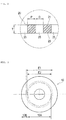
- Fig. 3 is a plan view simply illustrating each of regions 20A and 20B in the adhesion promotion device 100.
- the adhesion promotion device 100 has a main body portion 10 disposed between biological organs serving as a joint object.
- the main body portion 10 has a first region 10A and a second region 10B formed along an outer edge of the first region.
- the second region 10B includes an adhesion promotion portion 20 formed of a biodegradable sheet having a plurality of through-holes 25 and promoting adhesion of a biological tissue.
- the first region 10A includes a holding portion 30 having a holding force with respect to the biological organs which is stronger than that of the adhesion promotion portion 20.
- the adhesion promotion device 100 is applicable to a medical procedure (for example, anastomosis for a digestive tract) in which predetermined biological organs are joined to each other.
- a medical procedure for example, anastomosis for a digestive tract
- predetermined biological organs are joined to each other.
- the large intestine anastomosis will be described as an example of the medical procedure of using the adhesion promotion device 100.
- the main body portion 10 is configured to include a sheet-shaped member.
- the main body portion 10 has the first region 10A and the second region 10B formed along the outer edge of the first region 10A.
- the outer edge of the first region 10A is an imaginary line C1 in the drawing.
- the first region 10A and the second region 10B of the main body portion 10 include the adhesion promotion portion 20 formed of the biodegradable sheet having the plurality of through-holes 25.
- the first region 10A further includes the holding portion 30 formed on a rear surface 23 of the adhesion promotion portion 20, and an insertion portion 40 formed of an elastic member and into which a joining device 700 for joining the biological organs is inserted.
- the joining device 700 for joining the biological organs includes an automatic anastomosis device including a first engagement instrument 710 and a second engagement instrument 720 (refer to Figs. 7 to 10 ).
- the first engagement instrument 710 and the second engagement instrument 720 are anvils and trocars.
- the main body portion 10 formed of the biodegradable sheet can be preferably used for a predetermined medical procedure.
- an operator sets each of the first engagement instrument 710 and the second engagement instrument 720 in the biological organs serving as the joint object (refer to Fig. 8 ). Then, the operator sets the main body portion 10 in the biological organs serving as the joint object by inserting the first engagement instrument 710 into the insertion portion 40 of the main body portion 10. Then, the operator causes the first engagement instrument 710 and the second engagement instrument 720 to engage with each other in a state where the main body portion 10 is set in the biological organs serving as the joint object (refer to Fig. 9 ). In this manner, the operator can dispose the main body portion 10 between the biological organs serving as the joint object.
- the holding portion 30 provided in the first region 10A of the main body portion 10 is at least partially caught on the biological organs serving as the joint object. In this manner, the holding force with respect to the biological organs can be increased. In this manner, the operator can prevent the main body portion 10 from falling out of the biological organs due to misalignment of the main body portion 10.
- the operator causes the joining device 700 to puncture and excise a portion of the biological organ pinched by the joining device 700 and a portion of the main body portion 10.
- the operator causes the joining device 700 to excise each configuration member pinched by the joining device 700, and joins peripheries of the excised site at the same time. Then, the joining device 700 is removed outward of a living body (refer to Fig. 10 ).
- the joining device 700 punches each configuration member pinched by the joining device 700 by using a punching blade (not illustrated) incorporated in the first engagement instrument 710 or the second engagement instrument 720. Therefore, as illustrated in Figs. 3 and 10 , a region E2 where the biological organ joined by the joining device 700 is punched is located inward of a region E1 where the first engagement instrument 710 and the second engagement instrument 720 face and overlap each other across the main body portion 10.
- the first region 10A of the main body portion 10 is located inward of the region E1 where the first engagement instrument 710 and the second engagement instrument 720 face and overlap each other across the main body portion 10.
- the operator in a state where the operator pinches the main body portion 10 between the first engagement instrument 710 and the second engagement instrument 720, when the main body portion 10 pinched by the joining device 700 is punched, the operator can remove most of the holding portion 30.
- the operator when the operator removes the joining device 700 outward of the living body, the operator can remove most of the holding portion 30 provided in the first region 10A of the main body portion 10 outward of the living body.
- the holding portion 30 is formed of a biodegradable material
- at least a portion of the holding portion 30 may indwell the living body after the main body portion 10 is punched by the joining device 700.
- the holding portion 30 is degraded and absorbed inside the living body.
- the first region 10A of the main body portion 10 is formed of a biodegradable sheet.
- a material thereof is not particularly limited as long as the first region 10A can be disposed in the biological organ and further has the holding portion. Most of the first region 10A of the main body portion 10 is punched by the joining device 700. Accordingly, as illustrated in Fig. 1A , the first region 10A may not be formed by the adhesion promotion portion 20.
- the first region 10A of the main body portion 10 is located inward of the region E2 where the biological organ joined by the joining device 700 is punched. According to this configuration, when the joining device 700 is removed outward of the living body, all of the holding portion 30 provided in the first region 10A of the main body portion 10 can be removed outward of the living body. In this manner, even in a case where the holding portion 30 is formed of a non-biodegradable material, it is possible to reduce a possibility that foreign substances may indwell the body.
- the adhesion promotion portion 20 is provided in the second region 10B of the main body portion 10.
- the second region 10B of the main body portion 10 indwells the living body after being joined by the joining device 700 and the main body portion 10 is punched by the joining device 700. Therefore, the main body portion 10 can reliably fulfil a function of promoting adhesion with respect to the biological organs serving as the joint object by using the adhesion promotion portion 20 provided in the second region 10B of the main body portion 10.
- each of the through-holes 25 formed in the adhesion promotion portion 20 is regularly and periodically provided in a surface direction of the adhesion promotion portion 20.
- each of the through-hole 25 may be randomly provided in each portion in the surface direction of the adhesion promotion portion 20.
- each of the through-holes 25 extends substantially perpendicular between the front surface 21 and the rear surface 23 along a thickness direction (upward-downward direction in Fig. 2 ) of the adhesion promotion portion 20.
- Each of the through-holes 25 may be bent or curved in a zigzag manner between the front surface 21 and the rear surface 23, in a cross section taken along the thickness direction of the adhesion promotion portion 20.
- Each of the through-holes 25 has a substantially circular planar shape (shape when the front surface 21 of the adhesion promotion portion 20 or the rear surface 23 of the adhesion promotion portion 20 is viewed in a plan view) .
- the planar shape of each of the through-holes 25 is not particularly limited, and may be an elliptical shape or a polygonal shape (rectangular shape or triangular shape), for example.
- each of the through-holes 25 may have a different planar shape or cross-sectional shape.
- the adhesion promotion portion 20 has a substantially circular planar shape.
- the planar shape of the adhesion promotion portion 20 is not particularly limited, and may be an elliptical shape or a polygonal shape (rectangular shape or triangular shape), for example.
- a thickness (dimension T illustrated in Fig. 2 ) of the adhesion promotion portion 20 is not particularly limited. However, the thickness is preferably 0.05 to 0.3 mm, and is more preferably 0.1 to 0.2 mm. In a case where the thickness of the adhesion promotion portion 20 is 0.05 mm or larger (particularly in a case where the thickness is 0.1 mm or larger), the adhesion promotion portion 20 can be provided with strength to such an extent that the adhesion promotion portion 20 is not damaged when the adhesion promotion device 100 is handled.
- the adhesion promotion portion 20 can be provided with sufficient flexibility to follow the biological tissue after the adhesion promotion portion 20 closely adheres to the biological tissue to which the adhesion promotion portion 20 is applied.
- the adhesion promotion portion 20 has a ratio value of hole diameter D (distance D illustrated in Fig. 2 ) of the through-hole 25 with respect to a pitch P (distance P illustrated in Fig. 2 and a distance between the through-holes 25 adjacent to each other) of the through-holes 25 is 0.25 or greater and smaller than 40.
- the hole diameter D of the through-hole 25 is equal to a diameter of the perfect circle.
- the diameter of the perfect circle (diameter corresponding to a circle) having an area the same as an area of an opening portion (portion facing the front surface 21 or the rear surface 23 in the through-hole 25) of the through-hole 25 can be defined as the hole diameter D of the through-hole 25.
- the adhesion promotion portion 20 has the plurality of through-holes 25. Accordingly, a plurality of values exist in the hole diameter D corresponding to each of the through-holes 25. Therefore, in the present embodiment, in calculating the above-described ratio value, an arithmetic mean value of two or more values of the hole diameter D corresponding to each of the plurality of the through-holes 25 is used as a representative value of the hole diameter D.
- the pitch P of the plurality of through-holes 25 is defined by a shortest distance between the opening portions of the two through-holes 25.
- the pitch P a plurality of values exist in the pitch P corresponding to a combination of the through-holes 25 adjacent to each other. Therefore, in the present embodiment, in calculating the above-described ratio value, the arithmetic mean value of two or more values of the pitch P corresponding to each combination of the through-holes 25 adjacent to each other is used as the representative value of the pitch P.
- the pitch P, the hole diameter D, and the ratio of the hole diameter D with respect to the pitch P of the through-hole 25 are examples, and the configuration is not limited thereto.
- the adhesion promotion portion 20 can be formed of a biodegradable material.
- a material of forming the adhesion promotion portion 20 is not particularly limited, and includes a biodegradable resin, for example.
- the biodegradable resin it is possible to use known degradable (co)polymers disclosed in JP-T-2011-528275 , JP-T-2008-514719 , Pamphlet of International Publication No. 2008-1952 , or JP-T-2004-509205 .
- the biodegradable resin includes (1) a polymer selected from a group consisting of aliphatic polyester, polyester, polyacid anhydride, polyorthoester, polycarbonate, polyphosphazene, polyphosphate ester, polyvinyl alcohol, polypeptide, polysaccharide, protein, and cellulose, and (2) a copolymer formed of one or more monomers forming (1) described above.
- the biodegradable sheet includes at least one type of the biodegradable resin selected from the group consisting of the polymer selected from the group consisting of aliphatic polyester, polyester, polyacid anhydride, polyorthoester, polycarbonate, polyphosphazene, polyphosphate ester, polyvinyl alcohol, polypeptide, polysaccharide, protein, and cellulose, and the copolymer formed of one or more monomers forming the polymer.
- the biodegradable resin selected from the group consisting of the polymer selected from the group consisting of aliphatic polyester, polyester, polyacid anhydride, polyorthoester, polycarbonate, polyphosphazene, polyphosphate ester, polyvinyl alcohol, polypeptide, polysaccharide, protein, and cellulose, and the copolymer formed of one or more monomers forming the polymer.
- a method for manufacturing the adhesion promotion portion 20 is not particularly limited.
- the method includes a method for preparing a fiber formed of the above-described biodegradable resin and manufacturing a mesh-shaped sheet by using the fiber.
- the method for preparing the fiber formed of the biodegradable resin is not particularly limited.
- the method includes an electrospinning method (electrospinning method and electrostatic spinning method) and a melt blow method.
- the adhesion promotion portion 20 only one of the above-described methods may be selected and used, or two or more of the above-described methods may be selected and appropriately combined with each other.
- the biodegradable sheet according to the present invention may be manufactured by spinning the fiber formed of the above-described biodegradable resin in accordance with a usual method in the related art and knitting the obtained fiber into a mesh shape.
- the adhesion promotion portion 20 induces a biological reaction by a forming material such as the biodegradable resin forming the adhesion promotion portion 20.
- the adhesion promotion portion 20 induces expression of a biological component such as fibrin by the action.
- the biological component induced in this way can promote the adhesion by being accumulated to penetrate the through-hole 25 of the adhesion promotion portion 20. Therefore, the adhesion promotion portion 20 formed in the main body portion 10 of the adhesion promotion device 100 is disposed between the biological organs serving as the joint object. In this manner, the adhesion is promoted by the above-described mechanism.
- a material of the adhesion promotion portion 20 may not be biodegradable as long as the adhesion can be promoted.
- the adhesion promotion portion 20 may not have the through-hole 25 regardless of the material, as long as the adhesion can be promoted.
- the holding portion 30 is provided in the first region 10A of the main body portion 10.
- the adhesion promotion portion 20 is provided in the first region 10A of the main body portion 10, and the holding portion 30 is provided in the rear surface 23 of the adhesion promotion portion 20.
- the holding portion 30 has a plurality of projection portions 31. The plurality of the projection portion 31 applies a holding force with respect to the biological organ to the main body portion 10 by disposing the main body portion 10 in the biological organ serving as the joint object.
- the plurality of the projection portion 31 are conical projections.
- the plurality of the projection portion 31 utilizes a conical shape of each of the projection portions 31.
- sliding resistance force resistance
- the main body portion 10 can increase the holding force with respect to the biological organ by the plurality of projection portions 31. In this manner, an operator can prevent the adhesion promotion device 100 from falling out of the biological organ while a medical procedure is performed.
- a distal end of the plurality of conical projection portions 31 can partially penetrate a front surface tissue of the biological organ serving as the joint object. Therefore, the plurality of the projection portion 31 can more reliably generate the sliding resistance with respect to the biological organ serving as the joint object.
- a cross-sectional shape of each of the projection portions 31 is not particularly limited as long as the shape is a projection shape.
- the projection portion 31 can be formed in a polygonal shape such as a triangular shape and a trapezoidal shape, a dome shape, or a branch shape in which the shapes are combined with each other.
- a size of each of the projection portions 31 is not particularly limited. As illustrated in Fig. 1A , the size of each of the projection portions 31 may be constant, or may be irregular.
- the plurality of projection portions 31 are regularly provided with respect to a center position of the main body portion 10 in the surface direction of the main body portion 10. According to this configuration, the holding portion 30 provided in the first region 10A of the main body portion 10 more equally applies the holding force with respect to the biological organ in the surface direction of the main body portion 10.
- each disposition of the projection portions 31 is not particularly limited.
- each of the projection portions 31 may be irregularly provided, instead of being regularly provided with respect to the center position of the main body portion 10 in the surface direction of the main body portion 10.
- each of the projection portions 31 can be formed of the biodegradable resin, a thermoplastic elastomer, a thermoplastic resin such as nylon and PET, or metal such as a SUS wire, a copper wire, a titanium wire, and a nitinol wire.
- the material of each of the projection portions 31 is not particularly limited as long as each of the projection portions 31 can be caught on the biological organ in a state where the main body portion 10 is disposed in the biological organ serving as the joint object, and the holding force of the main body portion 10 can be increased for the biological organ.
- the method of preparing the projection portion 31 is not particularly limited.
- the holding portion 30 configured to include the projection portion 31 may be integrally formed on the outer surface of the main body portion 10, or may be molded separately from the main body portion 10 to be connected to the main body portion 10 by covering the outer surface of the main body portion 10. In this manner, a preparing method suitable for the forming material of the holding portion 30 can be adopted.
- the number of the projection portions 31 is two or more.
- the number of the projection portions 31 may be one.
- the projection portion 31 may have a hook shape for preventing slippage.
- the insertion portion 40 is provided at a center position of the first region 10A of the main body portion 10.
- an insertion hole 41 into which the joining device 700 is inserted is provided at the center position of the insertion portion 40.
- the insertion portion 40 has a substantially circular planar shape.
- the planar shape of the insertion portion 40 is not particularly limited, and may be an elliptical shape or a polygonal shape (rectangular shape or triangular shape), for example.
- the insertion portion 40 may be disposed at any position in the first region 10A of the main body portion 10.
- the insertion portion 40 includes the insertion hole 41 penetrating the main body portion 10 in the thickness direction.
- the insertion portion 40 is formed of an elastic material, and can be at least partially deformed along a direction in which the joining device 700 is inserted into the insertion hole 41 (refer to Fig. 7 ). According to this configuration, the insertion portion 40 can at least partially generate the sliding resistance in the joining device 700. Therefore, the main body portion 10 can increase the holding force with respect to the joining device 700 inserted into the insertion hole 41 by the insertion portion 40. Therefore, the operator can prevent the adhesion promotion device 100 from falling out of the joining device 700 while the medical procedure is performed.
- the insertion hole 41 has a cross-cut shape.
- An imaginary hole diameter d1 connecting outer edges of the insertion hole 41 can be formed to be 5 mm to 25 mm, for example.
- the planar shape of the insertion hole 41 is not limited to the cross-cut shape.
- the planar shape of the insertion hole 41 is not particularly limited as long as the planar shape is substantially the same as that of the joining device 700 inserted into the insertion hole 41, or a shape that can at least partially generate the sliding resistance with respect to the joining device 700 inserted into the insertion hole 41 and can increase the holding force of the main body portion 10 for the joining device 700.
- the insertion hole 41 may be disposed at any position in the insertion portion 40.
- the insertion portion 40 can be formed of rubber or silicone elastomer.
- a material of the insertion portion 40 is not particularly limited as long as the insertion portion 40 can at least partially generate the sliding resistance with respect to the joining device 700, when the operator sets the main body portion 10 in the biological organ serving as the joint object by inserting the joining device 700 into the insertion hole 41.
- a method of preparing the insertion portion 40 is not particularly limited.
- the insertion portion 40 may be formed integrally with the outer surface of the main body portion 10, or may be molded separately from the main body portion 10 to be connected to the outer surface of the main body portion 10. In this manner, a preparing method suitable for the forming material of the insertion portion 40 can be adopted.
- the method of preparing the insertion hole 41 is not particularly limited.
- the insertion hole 41 may be prepared in advance when the insertion portion 40 is prepared, or may be prepared by the operator while the medical procedure is performed.
- a medical instrument that can be inserted into the insertion hole 41 is not particularly limited.
- the adhesion promotion device 100 has the main body portion 10 disposed between the biological organs serving as the joint object.
- the main body portion 10 has the first region 10A and the second region 10B formed along the outer edge of the first region.
- the second region 10B includes the adhesion promotion portion 20 that promotes the adhesion of the biological tissue.
- the first region 10A includes the holding portion 30 having the holding force with respect to the biological organ which is stronger than that of the adhesion promotion portion 20.
- the holding portion 30 provided in the first region 10A of the main body portion 10 can at least partially generate the sliding resistance with respect to the biological organ serving as the joint object. Therefore, the main body portion 10 can increase the holding force with respect to the biological organ serving as the joint object by the holding portion 30. Therefore, the operator can prevent the main body portion 10 from falling out of the biological organ while the medical procedure is performed, and can effectively reduce risk factors of an anastomotic leakage of the biological organ.
- the adhesion promotion portion 20 provided in the second region 10B of the main body portion 10 can promote the adhesion of the biological organs by accumulating the biological component of the biological organ serving as the joint object in the through-hole 25.
- the holding portion 30 is integrally formed at a portion of the outer surface of the main body portion 10.
- the holding portion 30 is formed separately from the main body portion 10, and is connected to a portion of the outer surface of the main body portion 10 while covering the portion of the outer surface of the main body portion 10. According to this configuration, a preparing method suitable for the forming material of the holding portion 30 can be adopted.
- the holding portion 30 includes at least one of the projection portions 31. According to this configuration, the distal end of the projection portion 31 can partially penetrate a front surface tissue of the biological organ serving as the joint object. Therefore, the holding portion 30 can more reliably generate the sliding resistance with respect to the biological organ serving as the joint object. Therefore, while the medical procedure is performed, the operator can prevent the adhesion promotion device 100 from falling out of the biological organ, and can effectively reduce the risk factors of the anastomotic leakage of the biological organ.
- the main body portion 10 further has the insertion portion 40 formed of the elastic member, and the insertion portion 40 further has the insertion hole 41 into which the joining device 700 is inserted.
- the insertion portion 40 can be at least partially deformed along the direction in which the joining device 700 is inserted into the insertion hole 41.
- the insertion portion 40 can at least partially generate the sliding resistance with respect to the joining device 700 inserted into the insertion hole 41. Therefore, the main body portion 10 can increase the holding force with respect to the inserted joining device 700 by the insertion portion 40. Therefore, while the medical procedure is performed, the operator can prevent the adhesion promotion device 100 from falling out of the joining device 700, and can effectively reduce the risk factors of the anastomotic leakage of the biological organ.
- the main body portion 10 is disposed in one joint target site of the biological organ serving as the joint object, and the second region 10B is joined to the biological tissue by the medical instrument including the first engagement instrument 710 disposed in one joint target site of the biological organ, and the second engagement instrument 720 disposed in the other joint site of the biological organ and facing the first engagement instrument 710.
- the first region 10A is located inward of the region E1 where the first engagement instrument 710 and the second engagement instrument 720 face and overlap each other across the main body portion 10.
- the joining device 700 punches and excises a portion of the biological organ pinched by the joint portion of the joining device 700 and a portion of the main body portion 10, the joining device 700 joins peripheries of the excised site.
- the joining device 700 is removed outward of the living body, most of the holding portion 30 can be removed outward of the living body. Therefore, even when the holding portion 30 is formed of a non-biodegradable material, it is possible to reduce a possibility that foreign substances may indwell the body.
- the adhesion promotion device 100 has been described with reference to the embodiment.
- the present invention is not limited to the description of the above-described embodiment, and various modifications can be made within the scope not departing from the concept.
- modification examples of the holding portion 30 will be described.
- configurations and contents which are described above in the adhesion promotion device 100 will be appropriately omitted in the description.
- the contents not particularly described in the modification examples can be regarded as the same as those in the above-described embodiment.
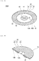
- Fig. 4A is a perspective view illustrating a modification example of the holding portion in an adhesion promotion device 100A.
- Fig. 4B is a cross-sectional view illustrating the modification example of the holding portion in the adhesion promotion device 100A.
- the adhesion promotion device 100A has the main body portion 10 disposed between the biological organs serving as the joint object.
- the main body portion 10 has the first region 10A and the second region 10B formed along the outer edge of the first region.
- the second region 10B includes the adhesion promotion portion 20 formed of a biodegradable sheet having the plurality of through-holes 25 and promoting the adhesion of the biological tissue.
- the first region 10A has a holding portion 30A having the holding force with respect to the biological organ which is stronger than that of the adhesion promotion portion 20, and the insertion portion 40 that can increase the holding force of the main body portion 10 for the joining device 700.
- the insertion portion 40 includes the insertion hole 41 into which the joining device 700 is inserted.
- the holding portion 30A has a friction portion 32 disposed in the biological organ serving as the joint object so that the holding force with respect to the biological organ is applied to the main body portion 10.
- the friction portion 32 can be formed of a coating agent such as a resin layer to which a particulate substance is added, and can generate the sliding resistance with respect to the biological organ serving as the joint object. Therefore, while the medical procedure is performed, the operator can prevent the adhesion promotion device 100 from falling out of the biological organ, and can effectively reduce the risk factors of the anastomotic leakage of the biological organ.
- a coating agent such as a resin layer to which a particulate substance is added
- a material of the friction portion 32 is not particularly limited.
- the friction portion 32 can be formed of a material that can at least partially generate the sliding resistance with respect to the front surface tissue of the biological organ serving as the joint object, and can increase the holding force of the main body portion 10 for the biological organ.
- a cross-sectional shape of the friction portion 32 is not limited to a configuration including a projection shape, and is not particularly limited.
- disposition of the friction portion 32 is not particularly limited.
- the friction portion 32 may be entirely provided in the first region 10A of the main body portion 10, or may be partially provided.
- a method of preparing the friction portion 32 is not particularly limited.
- the friction portion 32 may be integrally formed on the outer surface of the main body portion 10, or may be molded separately from the main body portion 10 to be connected to the main body portion 10 by covering the outer surface of the main body portion 10. In this manner, a preparing method suitable for the forming material of the friction portion 32 can be adopted.
- the thickness of the friction portion 32 is not particularly limited.
- the main body portion 10 of the adhesion promotion device 100 according to the present invention has the holding portion 30.
- the holding portion 30 may be configured so that the projection portion 31 and the friction portion 32 are appropriately combined with each other.
- the main body portion 10 may have the hole portion without having the insertion portion 40.
- the hole portion may be prepared in advance in the main body portion 10, or may be prepared by the operator while the medical procedure is performed. The operator can select various modifications of the main body portion 10 in accordance with a progress of the medical procedure.
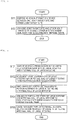
- Fig. 5 is a flowchart illustrating each procedure of the treatment method of using the adhesion promotion device.
- the treatment method includes disposing the adhesion promotion device including the sheet-shaped main body portion that promotes the adhesion of the biological tissue between one joint target sites and the other joint target site of the joint object of the biological organ (S11), and joining one joint target site and the other joint target site to each other in a state where at least a portion of the main body portion of the adhesion promotion device is disposed between one joint target site and the other joint target site (S12).
- the biological organs joined by using the treatment method and the joint target site in the biological organs are not particularly limited, and can be selected in any desired manner.
- large intestine anastomosis will be described as an example.
- any desired device can be selected from the above-described adhesion promotion devices.
- an application example of the adhesion promotion device 100 illustrated in Fig. 1 will be described.
- detailed description of a known medical procedure or a known joining device will be appropriately omitted.
- disposing the adhesion promotion device between the biological organs means at least any one of disposing the adhesion promotion device in a state of being in direct or indirect contact with the biological organs, disposing the adhesion promotion device in a state where a spatial gap is formed between the adhesion promotion device and the biological organs, and disposing the adhesion promotion device in both the states (for example, disposing the adhesion promotion device in a state where the adhesion promotion device is in contact with one biological organ and the adhesion promotion device is not in contact with the other biological organ).
- a "periphery” does not define a strict range (region), and means a predetermined range (region) as long as a treatment purpose (joining the biological organs to each other) can be achieved.
- a treatment purpose joining the biological organs to each other
- orders can be appropriately switched thereamong.
- "moving the portions to be relatively closer to each other” means both moving two or more objects to be closer to each other, and moving only one to be closer to the other one.
- Fig. 6 is a flowchart illustrating a procedure of an embodiment of the treatment method (large intestine anastomosis), and Figs. 7 to 10 are views for describing the large intestine anastomosis.
- the biological organ serving as the joint object is a large intestine cut due to excision of a cancer tumor.
- the biological organs serving as the joint object are a mouth side A1 of the cut large intestine and an anal side A2 of the cut large intestine.
- a procedure will be described in which a mouth portion periphery (one joint target site) on the mouth side A1 of the cut large intestine and a portion (other joint target site) of an intestinal wall on the anal side A2 of the cut large intestine are joined to each other.
- the treatment method according to the present embodiment includes disposing the adhesion promotion device 100 between the mouth portion periphery of the large intestine and the intestinal wall of the large intestine (S101), moving the mouth portion periphery of the large intestine and the intestinal wall of the large intestine to be relatively closer to each other (S102), pinching the main body portion 10 of the adhesion promotion device 100 between the mouth portion periphery of the large intestine and the intestinal wall of the large intestine (S103), joining the mouth portion periphery of the large intestine and the intestinal wall of the large intestine to each other in a state where the main body portion 10 of the adhesion promotion device 100 is pinched therebetween (S104), and causing the main body portion 10 of the adhesion promotion device 100 to indwell between the mouth portion periphery of the large intestine and the intestinal wall of the large intestine (S105).
- the operator inserts the first engagement instrument 710 of the joining device 700 into the mouth side A1 of the large intestine.
- the operator disposes the second engagement instrument 720 of the joining device 700 on the anal side A2 of the large intestine.
- the operator forms a through-hole A21 for inserting the second engagement instrument 720 of the joining device 700 into the anal side A2 of the large intestine.
- a timing at which the through-hole A21 is formed is not particularly limited as long as the timing is before the second engagement instrument 720 is disposed.
- the joining device 700 a known device used for the large intestine anastomosis can be used.
- the joining device 700 excises the biological tissue disposed between the first engagement instrument 710 and the second engagement instrument 720, and sutures a periphery of the excised biological tissue into a circumferential shape by using a stapler.
- the first engagement instrument 710 is an instrument including a cylindrical engagement target portion 711.
- the second engagement instrument 720 is an instrument including an engagement pin 721 to engage with and to be inserted into the engagement target portion 711 of the first engagement instrument 710.
- the operator inserts the engagement target portion 711 of the first engagement instrument 710 into the mouth side A1 of the large intestine, and performs purse-string suture in a projecting state of the engagement target portion 711, thereby forming a suture portion A11.
- An outer surface of the suture portion A11 has a shape partially projecting to a projection side due to the suture.
- the operator disposes the adhesion promotion device 100 between the mouth side A1 of the large intestine and the anal side A2 of the large intestine.
- the operator disposes the adhesion promotion device 100 so that the plurality of projection portions 31 formed on the rear surface 23 of the adhesion promotion portion 20 in the main body portion 10 come into contact with the suture portion A11 on the mouth side A1 of the large intestine.
- the operator causes the engagement target portion 711 included in the first engagement instrument 710 to pass through the insertion hole 41 formed in the insertion portion 40 of the main body portion 10. In this manner, the insertion portion 40 can at least partially generate the sliding resistance with respect to the joining device 700 inserted into the insertion hole 41.
- the main body portion 10 can increase the holding force with respect to the joining device 700 inserted into the insertion hole 41 by the insertion portion 40. Therefore, while the medical procedure is performed, the operator can prevent the adhesion promotion device 100 from falling out of the engagement target portion 711.
- the operator brings the plurality of projection portions 31 formed in the main body portion 10 into contact with the suture portion A11 on the mouth side A1 of the large intestine.
- the distal end of the plurality of projection portions 31 is disposed so that the distal end can partially penetrate the front surface tissue of the suture portion A11.
- the plurality of projection portions 31 can at least partially generate the sliding resistance with respect to the front surface tissue of the suture portion A11. Therefore, the main body portion 10 can increase the holding force with respect to the biological organ serving as the joint object by the plurality of projection portions 31.
- the operator can prevent the adhesion promotion device 100 from falling out of the suture portion A11, and can effectively reduce the risk factors of the anastomotic leakage of the biological organ.
- the operator may dispose the adhesion promotion device 100 on the anal side A2 of the large intestine by causing the engagement pin 721 included in the second engagement instrument 720 to pass through the insertion hole 41 formed in the insertion portion 40 of the main body portion 10.
- the operator engages the first engagement instrument 710 and the second engagement instrument 720 with each other by moving the first engagement instrument 710 and the second engagement instrument 720 to be relatively closer to each other as illustrated in Fig. 9 .
- the operator pinches the mouth portion periphery on the mouth side A1 of the large intestine, the main body portion 10 of the adhesion promotion device 100, and the periphery of the through-hole A21 formed on the intestinal wall on the anal side A2 of the large intestine, between the first engagement instrument 710 and the second engagement instrument 720.
- the operator causes the joining device 700 to excise a portion on the mouth side A1 of the large intestine, a portion of the main body portion 10 of the adhesion promotion device 100, and a portion on the anal side A2 of the large intestine pinched between the first engagement instrument 710 and the second engagement instrument 720.
- the operator operates the joining device 700 to join the peripheries of the excised site by using a stapler (not illustrated).
- the operator removes the joining device 700 outward of the living body from the anal side A2 of the large intestine via an anus, for example.
- the operator causes the joining device 700 to excise most of the plurality of projection portions 31 of the main body portion 10 disposed in the region E2 located inward of the region E1 where the first engagement instrument 710 and the second engagement instrument 720 face and overlap each other across the main body portion 10, and where the biological organs joined by the joining device 700 are punched, and can remove most of the plurality of projection portions 31 outward of the living body together with the joining device 700.
- the adhesion promotion portion 20 of the main body portion 10 disposed outward of the region E2 where the biological organs joined by the joining device 700 are punched indwells the living body in a state of being pinched between the mouth portion periphery on the mouth side A1 of the large intestine and the intestinal wall on the anal side A2 of the large intestine. Therefore, the adhesion promotion device 100 can reliably fulfil a function of promoting the adhesion with respect to the mouth portion periphery on the mouth side A1 of the large intestine and the intestinal wall on the anal side A2 of the large intestine which serve as the joint objects by using the adhesion promotion portion 20 of the main body portion 10.
- this treatment method a simple method of pinching the sheet-shaped main body portion included in the adhesion promotion device between one joint target site and the other joint target site is used. In this manner, it is possible to reduce the risk factors of the anastomotic leakage after a medical procedure for joining (for example, anastomosis for a digestive tract).
- the adhesion promotion device 100 when in use increases the holding force of the main body portion 10 with respect to the biological organ serving as the joint object by the holding portion 30. Accordingly, when the operator operates the adhesion promotion device 100 (when the adhesion promotion device 100 indwells the body), the operator can prevent the adhesion promotion device 100 from falling out of the biological organ. In addition, the adhesion promotion device 100 increases the holding force of the main body portion 10 with respect to the joining device 700 by the insertion portion 40. Accordingly, when the operator operates the adhesion promotion device 100 (when the adhesion promotion device 100 indwells the body), the operator can prevent the adhesion promotion device 100 from falling out of the joining device 700. Therefore, it is possible to reduce the risk factors of the anastomotic leakage after surgery.
Landscapes
- Health & Medical Sciences (AREA)
- Life Sciences & Earth Sciences (AREA)
- Surgery (AREA)
- Heart & Thoracic Surgery (AREA)
- Engineering & Computer Science (AREA)
- Biomedical Technology (AREA)
- Nuclear Medicine, Radiotherapy & Molecular Imaging (AREA)
- Medical Informatics (AREA)
- Molecular Biology (AREA)
- Animal Behavior & Ethology (AREA)
- General Health & Medical Sciences (AREA)
- Public Health (AREA)
- Veterinary Medicine (AREA)
- Surgical Instruments (AREA)
Abstract
Description
- The present invention relates to an adhesion promotion device.
- In a medical field, a medical procedure (for example, anastomosis for a digestive tract) of joining biological organs to each other by performing a surgical operation is known. In a case where the medical procedure as described above is performed, as a prognosis determinant after surgery, a fact is important that there is no delay in adhesion in a joint portion joined between the biological organs.
- In the medical procedure of joining the biological organs, various methods and various medical instruments are used. For example, a method of suturing the biological organs by using a biodegradable suture, or a method of using a mechanical joining device (refer to PTL 1) for performing anastomosis on the biological organs by using a stapler has been proposed. In particular, in a case where anastomosis is performed by using the mechanical joining device, compared to a method of using the suture, a joining force between the biological organs can be improved in the joint portion. Accordingly, risk factors of an anastomotic leakage can be reduced.
- PTL 1:
JP-T-2007-505708 - However, a progress degree of the adhesion in the joint portion depends on a state of biological tissues in a joint object site (joint target site) of a patient. Therefore, for example, even in a case where the joining device as disclosed in
PTL 1 is used, depending on the state of the biological tissues of the patient, there is a possibility that the risk factors of the anastomotic leakage cannot be sufficiently reduced. - Therefore, the present invention aims to provide an adhesion promotion device capable of reducing risk factors of an anastomotic leakage after a surgical operation is performed.
- According to an embodiment of the present invention, there is provided an adhesion promotion device having a main body portion disposed between biological organs serving as a joint object. The main body portion has a first region and a second region formed along an outer edge of the first region. The second region includes an adhesion promotion portion that promotes adhesion of a biological tissue. The first region includes a holding portion having a holding force with respect to the biological organs which is stronger than that of the adhesion promotion portion.
- According to the adhesion promotion device of the present invention, the adhesion of the biological tissue of the biological organs can be promoted by pinching the main body portion between the biological organs serving as the joint object. In addition, while a medical procedure is performed, an operator uses the holding portion provided in the main body portion to increase the holding force of the main body portion for the biological organs serving as the joint object. In this manner, the main body portion can be prevented from falling out of the biological organs. Therefore, the operator can effectively reduce risk factors of an anastomotic leakage of the biological organs.
-
- [
Fig. 1A] Fig. 1A is a perspective view when an adhesion promotion device according to an embodiment of the present invention is viewed from a rear surface side. - [
Fig. 1B] Fig. 1B is a perspective view when the adhesion promotion device according to the embodiment of the present invention is viewed from a front surface side. - [
Fig. 2] Fig. 2 is an enlarged cross-sectional view illustrating a portion of a cross section taken along line 2-2 inFig. 1B . - [
Fig. 3] Fig. 3 is a plan view simply illustrating each region of the adhesion promotion device. - [
Fig. 4A] Fig. 4A is a perspective view illustrating a modification example of a holding portion in the adhesion promotion device. - [
Fig. 4B] Fig. 4B is a cross-sectional view illustrating a modification example of the holding portion in the adhesion promotion device. - [
Fig. 5] Fig. 5 is a flowchart illustrating each procedure of a treatment method of using the adhesion promotion device. - [
Fig. 6] Fig. 6 is a flowchart illustrating a procedure of an embodiment (large intestine anastomosis) of the treatment method. - [
Fig. 7] Fig. 7 is a schematic cross-sectional perspective view for describing the large intestine anastomosis. - [
Fig. 8] Fig. 8 is a schematic cross-sectional view for describing the large intestine anastomosis. - [
Fig. 9] Fig. 9 is a schematic cross-sectional view for describing the large intestine anastomosis. - [
Fig. 10] Fig. 10 is a schematic cross-sectional view for describing the large intestine anastomosis. - Hereinafter, embodiments of the present invention will be described with reference to the accompanying drawings. In describing the drawings, the same reference numerals will be assigned to the same elements, and repeated description will be omitted. In addition, dimensional ratios in the drawings may be exaggerated for convenience of description, and may be different from actual ratios in some cases.
-
Fig. 1A is a perspective view when anadhesion promotion device 100 is viewed from arear surface 23 side.Fig. 1B is a perspective view when theadhesion promotion device 100 is viewed from afront surface 21 side.Fig. 2 is an enlarged cross-sectional view illustrating a portion of a cross section taken along line 2-2 inFig. 1B .Fig. 3 is a plan view simply illustrating each of regions 20A and 20B in theadhesion promotion device 100. - As illustrated in
Fig. 1A , theadhesion promotion device 100 has amain body portion 10 disposed between biological organs serving as a joint object. Themain body portion 10 has afirst region 10A and asecond region 10B formed along an outer edge of the first region. Thesecond region 10B includes anadhesion promotion portion 20 formed of a biodegradable sheet having a plurality of through-holes 25 and promoting adhesion of a biological tissue. Thefirst region 10A includes aholding portion 30 having a holding force with respect to the biological organs which is stronger than that of theadhesion promotion portion 20. - As illustrated in
Figs. 7 to 10 , theadhesion promotion device 100 is applicable to a medical procedure (for example, anastomosis for a digestive tract) in which predetermined biological organs are joined to each other. As will be described later, in describing the present specification, the large intestine anastomosis will be described as an example of the medical procedure of using theadhesion promotion device 100. - As illustrated in
Fig. 1A , themain body portion 10 is configured to include a sheet-shaped member. - The
main body portion 10 has thefirst region 10A and thesecond region 10B formed along the outer edge of thefirst region 10A. The outer edge of thefirst region 10A is an imaginary line C1 in the drawing. - As illustrated in
Fig. 1A , thefirst region 10A and thesecond region 10B of themain body portion 10 include theadhesion promotion portion 20 formed of the biodegradable sheet having the plurality of through-holes 25. - In addition, as illustrated in
Figs. 1A and7 , thefirst region 10A further includes the holdingportion 30 formed on arear surface 23 of theadhesion promotion portion 20, and aninsertion portion 40 formed of an elastic member and into which a joiningdevice 700 for joining the biological organs is inserted. - For example, the joining device 700 (medical instrument) for joining the biological organs includes an automatic anastomosis device including a
first engagement instrument 710 and a second engagement instrument 720 (refer toFigs. 7 to 10 ). For example, thefirst engagement instrument 710 and thesecond engagement instrument 720 are anvils and trocars. Themain body portion 10 formed of the biodegradable sheet can be preferably used for a predetermined medical procedure. - In a case where the
main body portion 10 is used for the medical procedure of using the joiningdevice 700, an operator (operator such as a doctor) sets each of thefirst engagement instrument 710 and thesecond engagement instrument 720 in the biological organs serving as the joint object (refer toFig. 8 ). Then, the operator sets themain body portion 10 in the biological organs serving as the joint object by inserting thefirst engagement instrument 710 into theinsertion portion 40 of themain body portion 10. Then, the operator causes thefirst engagement instrument 710 and thesecond engagement instrument 720 to engage with each other in a state where themain body portion 10 is set in the biological organs serving as the joint object (refer toFig. 9 ). In this manner, the operator can dispose themain body portion 10 between the biological organs serving as the joint object. - In the medical procedure, in the
main body portion 10, the holdingportion 30 provided in thefirst region 10A of themain body portion 10 is at least partially caught on the biological organs serving as the joint object. In this manner, the holding force with respect to the biological organs can be increased. In this manner, the operator can prevent themain body portion 10 from falling out of the biological organs due to misalignment of themain body portion 10. - In addition, in a state where the
first engagement instrument 710 and thesecond engagement instrument 720 engage with each other, the operator causes the joiningdevice 700 to puncture and excise a portion of the biological organ pinched by the joiningdevice 700 and a portion of themain body portion 10. In addition, the operator causes the joiningdevice 700 to excise each configuration member pinched by the joiningdevice 700, and joins peripheries of the excised site at the same time. Then, the joiningdevice 700 is removed outward of a living body (refer toFig. 10 ). - In the medical procedure, the joining
device 700 punches each configuration member pinched by the joiningdevice 700 by using a punching blade (not illustrated) incorporated in thefirst engagement instrument 710 or thesecond engagement instrument 720. Therefore, as illustrated inFigs. 3 and10 , a region E2 where the biological organ joined by the joiningdevice 700 is punched is located inward of a region E1 where thefirst engagement instrument 710 and thesecond engagement instrument 720 face and overlap each other across themain body portion 10. - In addition, as illustrated in
Figs. 1A and3 , thefirst region 10A of themain body portion 10 is located inward of the region E1 where thefirst engagement instrument 710 and thesecond engagement instrument 720 face and overlap each other across themain body portion 10. According to this configuration, in a state where the operator pinches themain body portion 10 between thefirst engagement instrument 710 and thesecond engagement instrument 720, when themain body portion 10 pinched by the joiningdevice 700 is punched, the operator can remove most of the holdingportion 30. In addition, when the operator removes the joiningdevice 700 outward of the living body, the operator can remove most of the holdingportion 30 provided in thefirst region 10A of themain body portion 10 outward of the living body. For example, in a case where the holdingportion 30 is formed of a biodegradable material, in the above-described medical procedure, at least a portion of the holdingportion 30 may indwell the living body after themain body portion 10 is punched by the joiningdevice 700. In a case where the holdingportion 30 is formed of the biodegradable material, the holdingportion 30 is degraded and absorbed inside the living body. - It is preferable that the
first region 10A of themain body portion 10 is formed of a biodegradable sheet. However, a material thereof is not particularly limited as long as thefirst region 10A can be disposed in the biological organ and further has the holding portion. Most of thefirst region 10A of themain body portion 10 is punched by the joiningdevice 700. Accordingly, as illustrated inFig. 1A , thefirst region 10A may not be formed by theadhesion promotion portion 20. - As illustrated in
Figs. 1A and3 , it is preferable that thefirst region 10A of themain body portion 10 is located inward of the region E2 where the biological organ joined by the joiningdevice 700 is punched. According to this configuration, when the joiningdevice 700 is removed outward of the living body, all of the holdingportion 30 provided in thefirst region 10A of themain body portion 10 can be removed outward of the living body. In this manner, even in a case where the holdingportion 30 is formed of a non-biodegradable material, it is possible to reduce a possibility that foreign substances may indwell the body. - On the other hand, as illustrated in
Fig. 1A , only theadhesion promotion portion 20 is provided in thesecond region 10B of themain body portion 10. In the above-described medical procedure, in a state of being pinched between thefirst engagement instrument 710 and thesecond engagement instrument 720, thesecond region 10B of themain body portion 10 indwells the living body after being joined by the joiningdevice 700 and themain body portion 10 is punched by the joiningdevice 700. Therefore, themain body portion 10 can reliably fulfil a function of promoting adhesion with respect to the biological organs serving as the joint object by using theadhesion promotion portion 20 provided in thesecond region 10B of themain body portion 10. - As illustrated in
Figs. 1A and 1B , each of the through-holes 25 formed in theadhesion promotion portion 20 is regularly and periodically provided in a surface direction of theadhesion promotion portion 20. However, each of the through-hole 25 may be randomly provided in each portion in the surface direction of theadhesion promotion portion 20. - As illustrated in
Fig. 2 , each of the through-holes 25 extends substantially perpendicular between thefront surface 21 and therear surface 23 along a thickness direction (upward-downward direction inFig. 2 ) of theadhesion promotion portion 20. Each of the through-holes 25 may be bent or curved in a zigzag manner between thefront surface 21 and therear surface 23, in a cross section taken along the thickness direction of theadhesion promotion portion 20. - Each of the through-
holes 25 has a substantially circular planar shape (shape when thefront surface 21 of theadhesion promotion portion 20 or therear surface 23 of theadhesion promotion portion 20 is viewed in a plan view) . However, the planar shape of each of the through-holes 25 is not particularly limited, and may be an elliptical shape or a polygonal shape (rectangular shape or triangular shape), for example. In addition, each of the through-holes 25 may have a different planar shape or cross-sectional shape. - The
adhesion promotion portion 20 has a substantially circular planar shape. However, the planar shape of theadhesion promotion portion 20 is not particularly limited, and may be an elliptical shape or a polygonal shape (rectangular shape or triangular shape), for example. - A thickness (dimension T illustrated in
Fig. 2 ) of theadhesion promotion portion 20 is not particularly limited. However, the thickness is preferably 0.05 to 0.3 mm, and is more preferably 0.1 to 0.2 mm. In a case where the thickness of theadhesion promotion portion 20 is 0.05 mm or larger (particularly in a case where the thickness is 0.1 mm or larger), theadhesion promotion portion 20 can be provided with strength to such an extent that theadhesion promotion portion 20 is not damaged when theadhesion promotion device 100 is handled. On the other hand, in a case where the thickness of theadhesion promotion portion 20 is 0.3 mm or smaller (particularly when the thickness is 0.2 mm or smaller), theadhesion promotion portion 20 can be provided with sufficient flexibility to follow the biological tissue after theadhesion promotion portion 20 closely adheres to the biological tissue to which theadhesion promotion portion 20 is applied. - It is preferable that the
adhesion promotion portion 20 has a ratio value of hole diameter D (distance D illustrated inFig. 2 ) of the through-hole 25 with respect to a pitch P (distance P illustrated inFig. 2 and a distance between the through-holes 25 adjacent to each other) of the through-holes 25 is 0.25 or greater and smaller than 40. In a case where the planar shape of the through-hole 25 is a perfect circle, the hole diameter D of the through-hole 25 is equal to a diameter of the perfect circle. On the other hand, in a case where the planar shape of the through-hole 25 is not the perfect circle, the diameter of the perfect circle (diameter corresponding to a circle) having an area the same as an area of an opening portion (portion facing thefront surface 21 or therear surface 23 in the through-hole 25) of the through-hole 25 can be defined as the hole diameter D of the through-hole 25. - The
adhesion promotion portion 20 has the plurality of through-holes 25. Accordingly, a plurality of values exist in the hole diameter D corresponding to each of the through-holes 25. Therefore, in the present embodiment, in calculating the above-described ratio value, an arithmetic mean value of two or more values of the hole diameter D corresponding to each of the plurality of the through-holes 25 is used as a representative value of the hole diameter D. On the other hand, the pitch P of the plurality of through-holes 25 is defined by a shortest distance between the opening portions of the two through-holes 25. However, with regard to the value of the pitch P, a plurality of values exist in the pitch P corresponding to a combination of the through-holes 25 adjacent to each other. Therefore, in the present embodiment, in calculating the above-described ratio value, the arithmetic mean value of two or more values of the pitch P corresponding to each combination of the through-holes 25 adjacent to each other is used as the representative value of the pitch P. - The pitch P, the hole diameter D, and the ratio of the hole diameter D with respect to the pitch P of the through-
hole 25 are examples, and the configuration is not limited thereto. - The
adhesion promotion portion 20 can be formed of a biodegradable material. A material of forming theadhesion promotion portion 20 is not particularly limited, and includes a biodegradable resin, for example. For example, as the biodegradable resin, it is possible to use known degradable (co)polymers disclosed inJP-T-2011-528275 JP-T-2008-514719 2008-1952 JP-T-2004-509205 - A method for manufacturing the
adhesion promotion portion 20 is not particularly limited. For example, the method includes a method for preparing a fiber formed of the above-described biodegradable resin and manufacturing a mesh-shaped sheet by using the fiber. The method for preparing the fiber formed of the biodegradable resin is not particularly limited. For example, the method includes an electrospinning method (electrospinning method and electrostatic spinning method) and a melt blow method. For theadhesion promotion portion 20, only one of the above-described methods may be selected and used, or two or more of the above-described methods may be selected and appropriately combined with each other. As still another example of the method for manufacturing theadhesion promotion portion 20, the biodegradable sheet according to the present invention may be manufactured by spinning the fiber formed of the above-described biodegradable resin in accordance with a usual method in the related art and knitting the obtained fiber into a mesh shape. - The
adhesion promotion portion 20 induces a biological reaction by a forming material such as the biodegradable resin forming theadhesion promotion portion 20. Theadhesion promotion portion 20 induces expression of a biological component such as fibrin by the action. The biological component induced in this way can promote the adhesion by being accumulated to penetrate the through-hole 25 of theadhesion promotion portion 20. Therefore, theadhesion promotion portion 20 formed in themain body portion 10 of theadhesion promotion device 100 is disposed between the biological organs serving as the joint object. In this manner, the adhesion is promoted by the above-described mechanism. - A material of the
adhesion promotion portion 20 may not be biodegradable as long as the adhesion can be promoted. In addition, theadhesion promotion portion 20 may not have the through-hole 25 regardless of the material, as long as the adhesion can be promoted. - As illustrated in
Fig. 1A , the holdingportion 30 is provided in thefirst region 10A of themain body portion 10. Theadhesion promotion portion 20 is provided in thefirst region 10A of themain body portion 10, and the holdingportion 30 is provided in therear surface 23 of theadhesion promotion portion 20. In addition, the holdingportion 30 has a plurality ofprojection portions 31. The plurality of theprojection portion 31 applies a holding force with respect to the biological organ to themain body portion 10 by disposing themain body portion 10 in the biological organ serving as the joint object. - As illustrated in
Fig. 1A , the plurality of theprojection portion 31 are conical projections. The plurality of theprojection portion 31 utilizes a conical shape of each of theprojection portions 31. In this manner, sliding resistance (friction resistance) can be at least partially generated for the biological organ serving as the joint object. According to this configuration, themain body portion 10 can increase the holding force with respect to the biological organ by the plurality ofprojection portions 31. In this manner, an operator can prevent theadhesion promotion device 100 from falling out of the biological organ while a medical procedure is performed. - A distal end of the plurality of
conical projection portions 31 can partially penetrate a front surface tissue of the biological organ serving as the joint object. Therefore, the plurality of theprojection portion 31 can more reliably generate the sliding resistance with respect to the biological organ serving as the joint object. - A cross-sectional shape of each of the
projection portions 31 is not particularly limited as long as the shape is a projection shape. For example, theprojection portion 31 can be formed in a polygonal shape such as a triangular shape and a trapezoidal shape, a dome shape, or a branch shape in which the shapes are combined with each other. - In addition, a size of each of the
projection portions 31 is not particularly limited. As illustrated inFig. 1A , the size of each of theprojection portions 31 may be constant, or may be irregular. - As illustrated in
Fig. 1A , the plurality ofprojection portions 31 are regularly provided with respect to a center position of themain body portion 10 in the surface direction of themain body portion 10. According to this configuration, the holdingportion 30 provided in thefirst region 10A of themain body portion 10 more equally applies the holding force with respect to the biological organ in the surface direction of themain body portion 10. - Each disposition of the
projection portions 31 is not particularly limited. For example, each of theprojection portions 31 may be irregularly provided, instead of being regularly provided with respect to the center position of themain body portion 10 in the surface direction of themain body portion 10. - In addition, for example, each of the
projection portions 31 can be formed of the biodegradable resin, a thermoplastic elastomer, a thermoplastic resin such as nylon and PET, or metal such as a SUS wire, a copper wire, a titanium wire, and a nitinol wire. The material of each of theprojection portions 31 is not particularly limited as long as each of theprojection portions 31 can be caught on the biological organ in a state where themain body portion 10 is disposed in the biological organ serving as the joint object, and the holding force of themain body portion 10 can be increased for the biological organ. - In addition, the method of preparing the
projection portion 31 is not particularly limited. The holdingportion 30 configured to include theprojection portion 31 may be integrally formed on the outer surface of themain body portion 10, or may be molded separately from themain body portion 10 to be connected to themain body portion 10 by covering the outer surface of themain body portion 10. In this manner, a preparing method suitable for the forming material of the holdingportion 30 can be adopted. - In addition, an example has been described in which the number of the
projection portions 31 is two or more. However, the number of theprojection portions 31 may be one. - In addition, the
projection portion 31 may have a hook shape for preventing slippage. - As illustrated in
Figs. 1A and 1B , theinsertion portion 40 is provided at a center position of thefirst region 10A of themain body portion 10. In addition, aninsertion hole 41 into which the joiningdevice 700 is inserted is provided at the center position of theinsertion portion 40. - As illustrated in
Figs. 1A and 1B , theinsertion portion 40 has a substantially circular planar shape. However, the planar shape of theinsertion portion 40 is not particularly limited, and may be an elliptical shape or a polygonal shape (rectangular shape or triangular shape), for example. In addition, theinsertion portion 40 may be disposed at any position in thefirst region 10A of themain body portion 10. - As illustrated in
Figs. 1A and 1B , theinsertion portion 40 includes theinsertion hole 41 penetrating themain body portion 10 in the thickness direction. Theinsertion portion 40 is formed of an elastic material, and can be at least partially deformed along a direction in which the joiningdevice 700 is inserted into the insertion hole 41 (refer toFig. 7 ). According to this configuration, theinsertion portion 40 can at least partially generate the sliding resistance in the joiningdevice 700. Therefore, themain body portion 10 can increase the holding force with respect to the joiningdevice 700 inserted into theinsertion hole 41 by theinsertion portion 40. Therefore, the operator can prevent theadhesion promotion device 100 from falling out of the joiningdevice 700 while the medical procedure is performed. - As illustrated in
Figs. 1A and 1B , theinsertion hole 41 has a cross-cut shape. An imaginary hole diameter d1 connecting outer edges of theinsertion hole 41 can be formed to be 5 mm to 25 mm, for example. The planar shape of theinsertion hole 41 is not limited to the cross-cut shape. The planar shape of theinsertion hole 41 is not particularly limited as long as the planar shape is substantially the same as that of the joiningdevice 700 inserted into theinsertion hole 41, or a shape that can at least partially generate the sliding resistance with respect to the joiningdevice 700 inserted into theinsertion hole 41 and can increase the holding force of themain body portion 10 for the joiningdevice 700. In addition, theinsertion hole 41 may be disposed at any position in theinsertion portion 40. - For example, the
insertion portion 40 can be formed of rubber or silicone elastomer. A material of theinsertion portion 40 is not particularly limited as long as theinsertion portion 40 can at least partially generate the sliding resistance with respect to the joiningdevice 700, when the operator sets themain body portion 10 in the biological organ serving as the joint object by inserting the joiningdevice 700 into theinsertion hole 41. - In addition, a method of preparing the
insertion portion 40 is not particularly limited. Theinsertion portion 40 may be formed integrally with the outer surface of themain body portion 10, or may be molded separately from themain body portion 10 to be connected to the outer surface of themain body portion 10. In this manner, a preparing method suitable for the forming material of theinsertion portion 40 can be adopted. - In addition, the method of preparing the
insertion hole 41 is not particularly limited. Theinsertion hole 41 may be prepared in advance when theinsertion portion 40 is prepared, or may be prepared by the operator while the medical procedure is performed. - In addition, without being limited to the joining
device 700 that joins the biological organs, a medical instrument that can be inserted into theinsertion hole 41 is not particularly limited. - As described above, the
adhesion promotion device 100 according to the present embodiment has themain body portion 10 disposed between the biological organs serving as the joint object. Themain body portion 10 has thefirst region 10A and thesecond region 10B formed along the outer edge of the first region. Thesecond region 10B includes theadhesion promotion portion 20 that promotes the adhesion of the biological tissue. Thefirst region 10A includes the holdingportion 30 having the holding force with respect to the biological organ which is stronger than that of theadhesion promotion portion 20. - According to the
adhesion promotion device 100 as described above, the holdingportion 30 provided in thefirst region 10A of themain body portion 10 can at least partially generate the sliding resistance with respect to the biological organ serving as the joint object. Therefore, themain body portion 10 can increase the holding force with respect to the biological organ serving as the joint object by the holdingportion 30. Therefore, the operator can prevent themain body portion 10 from falling out of the biological organ while the medical procedure is performed, and can effectively reduce risk factors of an anastomotic leakage of the biological organ. In addition, theadhesion promotion portion 20 provided in thesecond region 10B of themain body portion 10 can promote the adhesion of the biological organs by accumulating the biological component of the biological organ serving as the joint object in the through-hole 25. - The holding
portion 30 is integrally formed at a portion of the outer surface of themain body portion 10. Alternatively, the holdingportion 30 is formed separately from themain body portion 10, and is connected to a portion of the outer surface of themain body portion 10 while covering the portion of the outer surface of themain body portion 10. According to this configuration, a preparing method suitable for the forming material of the holdingportion 30 can be adopted. - The holding
portion 30 includes at least one of theprojection portions 31. According to this configuration, the distal end of theprojection portion 31 can partially penetrate a front surface tissue of the biological organ serving as the joint object. Therefore, the holdingportion 30 can more reliably generate the sliding resistance with respect to the biological organ serving as the joint object. Therefore, while the medical procedure is performed, the operator can prevent theadhesion promotion device 100 from falling out of the biological organ, and can effectively reduce the risk factors of the anastomotic leakage of the biological organ. - The
main body portion 10 further has theinsertion portion 40 formed of the elastic member, and theinsertion portion 40 further has theinsertion hole 41 into which the joiningdevice 700 is inserted. According to this configuration, theinsertion portion 40 can be at least partially deformed along the direction in which the joiningdevice 700 is inserted into theinsertion hole 41. In this manner, theinsertion portion 40 can at least partially generate the sliding resistance with respect to the joiningdevice 700 inserted into theinsertion hole 41. Therefore, themain body portion 10 can increase the holding force with respect to the inserted joiningdevice 700 by theinsertion portion 40. Therefore, while the medical procedure is performed, the operator can prevent theadhesion promotion device 100 from falling out of the joiningdevice 700, and can effectively reduce the risk factors of the anastomotic leakage of the biological organ. - The
main body portion 10 is disposed in one joint target site of the biological organ serving as the joint object, and thesecond region 10B is joined to the biological tissue by the medical instrument including thefirst engagement instrument 710 disposed in one joint target site of the biological organ, and thesecond engagement instrument 720 disposed in the other joint site of the biological organ and facing thefirst engagement instrument 710. In addition, when themain body portion 10 is joined to the biological tissue by thefirst engagement instrument 710 and thesecond engagement instrument 720, thefirst region 10A is located inward of the region E1 where thefirst engagement instrument 710 and thesecond engagement instrument 720 face and overlap each other across themain body portion 10. According to this configuration, while the joiningdevice 700 punches and excises a portion of the biological organ pinched by the joint portion of the joiningdevice 700 and a portion of themain body portion 10, the joiningdevice 700 joins peripheries of the excised site. When the joiningdevice 700 is removed outward of the living body, most of the holdingportion 30 can be removed outward of the living body. Therefore, even when the holdingportion 30 is formed of a non-biodegradable material, it is possible to reduce a possibility that foreign substances may indwell the body. - Hitherto, the
adhesion promotion device 100 has been described with reference to the embodiment. However, the present invention is not limited to the description of the above-described embodiment, and various modifications can be made within the scope not departing from the concept. In the following description, modification examples of the holdingportion 30 will be described. In describing the modification examples, configurations and contents which are described above in theadhesion promotion device 100 will be appropriately omitted in the description. In addition, the contents not particularly described in the modification examples can be regarded as the same as those in the above-described embodiment. -
Fig. 4A is a perspective view illustrating a modification example of the holding portion in anadhesion promotion device 100A.Fig. 4B is a cross-sectional view illustrating the modification example of the holding portion in theadhesion promotion device 100A. - As illustrated in
Figs. 4A and 4B , theadhesion promotion device 100A has themain body portion 10 disposed between the biological organs serving as the joint object. Themain body portion 10 has thefirst region 10A and thesecond region 10B formed along the outer edge of the first region. Thesecond region 10B includes theadhesion promotion portion 20 formed of a biodegradable sheet having the plurality of through-holes 25 and promoting the adhesion of the biological tissue. Thefirst region 10A has a holding portion 30A having the holding force with respect to the biological organ which is stronger than that of theadhesion promotion portion 20, and theinsertion portion 40 that can increase the holding force of themain body portion 10 for the joiningdevice 700. Theinsertion portion 40 includes theinsertion hole 41 into which the joiningdevice 700 is inserted. - As illustrated in
Figs. 4A and 4B , the holding portion 30A has afriction portion 32 disposed in the biological organ serving as the joint object so that the holding force with respect to the biological organ is applied to themain body portion 10. - For example, the
friction portion 32 can be formed of a coating agent such as a resin layer to which a particulate substance is added, and can generate the sliding resistance with respect to the biological organ serving as the joint object. Therefore, while the medical procedure is performed, the operator can prevent theadhesion promotion device 100 from falling out of the biological organ, and can effectively reduce the risk factors of the anastomotic leakage of the biological organ. - A material of the
friction portion 32 is not particularly limited. Thefriction portion 32 can be formed of a material that can at least partially generate the sliding resistance with respect to the front surface tissue of the biological organ serving as the joint object, and can increase the holding force of themain body portion 10 for the biological organ. In addition, a cross-sectional shape of thefriction portion 32 is not limited to a configuration including a projection shape, and is not particularly limited. - In addition, disposition of the
friction portion 32 is not particularly limited. For example, as illustrated inFigs. 4A and 4B , thefriction portion 32 may be entirely provided in thefirst region 10A of themain body portion 10, or may be partially provided. - In addition, a method of preparing the
friction portion 32 is not particularly limited. Thefriction portion 32 may be integrally formed on the outer surface of themain body portion 10, or may be molded separately from themain body portion 10 to be connected to themain body portion 10 by covering the outer surface of themain body portion 10. In this manner, a preparing method suitable for the forming material of thefriction portion 32 can be adopted. In addition, the thickness of thefriction portion 32 is not particularly limited. - Hitherto, an example of the configuration of the adhesion promotion device has been described. However, a specific configuration thereof is not limited as long as the
main body portion 10 of theadhesion promotion device 100 according to the present invention has the holdingportion 30. For example, the holdingportion 30 may be configured so that theprojection portion 31 and thefriction portion 32 are appropriately combined with each other. In addition, themain body portion 10 may have the hole portion without having theinsertion portion 40. The hole portion may be prepared in advance in themain body portion 10, or may be prepared by the operator while the medical procedure is performed. The operator can select various modifications of themain body portion 10 in accordance with a progress of the medical procedure. - Next, a treatment method of using the adhesion promotion device will be described.
-
Fig. 5 is a flowchart illustrating each procedure of the treatment method of using the adhesion promotion device. - The treatment method includes disposing the adhesion promotion device including the sheet-shaped main body portion that promotes the adhesion of the biological tissue between one joint target sites and the other joint target site of the joint object of the biological organ (S11), and joining one joint target site and the other joint target site to each other in a state where at least a portion of the main body portion of the adhesion promotion device is disposed between one joint target site and the other joint target site (S12).
- The biological organs joined by using the treatment method and the joint target site in the biological organs are not particularly limited, and can be selected in any desired manner. However, in the following description, large intestine anastomosis will be described as an example. In addition, as the adhesion promotion device used in each medical procedure described below, for example, any desired device can be selected from the above-described adhesion promotion devices. However, in the following description, as a representative example that can be preferably used for each medical procedure, an application example of the
adhesion promotion device 100 illustrated inFig. 1 will be described. In addition, in each medical procedure described below, detailed description of a known medical procedure or a known joining device will be appropriately omitted. - Hereinafter, in the description in the present specification, "disposing the adhesion promotion device between the biological organs" means at least any one of disposing the adhesion promotion device in a state of being in direct or indirect contact with the biological organs, disposing the adhesion promotion device in a state where a spatial gap is formed between the adhesion promotion device and the biological organs, and disposing the adhesion promotion device in both the states (for example, disposing the adhesion promotion device in a state where the adhesion promotion device is in contact with one biological organ and the adhesion promotion device is not in contact with the other biological organ). In addition, in the description in the present specification, a "periphery" does not define a strict range (region), and means a predetermined range (region) as long as a treatment purpose (joining the biological organs to each other) can be achieved. In addition, as long as the treatment purpose can be achieved, in the medical procedure described in each treatment method, orders can be appropriately switched thereamong. In addition, in the description in the present specification, "moving the portions to be relatively closer to each other" means both moving two or more objects to be closer to each other, and moving only one to be closer to the other one.
-
Fig. 6 is a flowchart illustrating a procedure of an embodiment of the treatment method (large intestine anastomosis), andFigs. 7 to 10 are views for describing the large intestine anastomosis. - In the treatment method according to the present embodiment, the biological organ serving as the joint object is a large intestine cut due to excision of a cancer tumor. Specifically, the biological organs serving as the joint object are a mouth side A1 of the cut large intestine and an anal side A2 of the cut large intestine. In the following description, a procedure will be described in which a mouth portion periphery (one joint target site) on the mouth side A1 of the cut large intestine and a portion (other joint target site) of an intestinal wall on the anal side A2 of the cut large intestine are joined to each other.
- As illustrated in
Fig. 6 , the treatment method according to the present embodiment includes disposing theadhesion promotion device 100 between the mouth portion periphery of the large intestine and the intestinal wall of the large intestine (S101), moving the mouth portion periphery of the large intestine and the intestinal wall of the large intestine to be relatively closer to each other (S102), pinching themain body portion 10 of theadhesion promotion device 100 between the mouth portion periphery of the large intestine and the intestinal wall of the large intestine (S103), joining the mouth portion periphery of the large intestine and the intestinal wall of the large intestine to each other in a state where themain body portion 10 of theadhesion promotion device 100 is pinched therebetween (S104), and causing themain body portion 10 of theadhesion promotion device 100 to indwell between the mouth portion periphery of the large intestine and the intestinal wall of the large intestine (S105). - Next, the treatment method according to the present embodiment will be described in detail with reference to
Figs. 7 to 10 . - As illustrated in
Fig. 7 , the operator inserts thefirst engagement instrument 710 of the joiningdevice 700 into the mouth side A1 of the large intestine. The operator disposes thesecond engagement instrument 720 of the joiningdevice 700 on the anal side A2 of the large intestine. Before thesecond engagement instrument 720 is disposed on the anal side A2 of the large intestine, the operator forms a through-hole A21 for inserting thesecond engagement instrument 720 of the joiningdevice 700 into the anal side A2 of the large intestine. A timing at which the through-hole A21 is formed is not particularly limited as long as the timing is before thesecond engagement instrument 720 is disposed. - For example, as the joining
device 700, a known device used for the large intestine anastomosis can be used. As thefirst engagement instrument 710 and thesecond engagement instrument 720 engage with each other, the joiningdevice 700 excises the biological tissue disposed between thefirst engagement instrument 710 and thesecond engagement instrument 720, and sutures a periphery of the excised biological tissue into a circumferential shape by using a stapler. For example, thefirst engagement instrument 710 is an instrument including a cylindricalengagement target portion 711. For example, thesecond engagement instrument 720 is an instrument including anengagement pin 721 to engage with and to be inserted into theengagement target portion 711 of thefirst engagement instrument 710. - The operator inserts the
engagement target portion 711 of thefirst engagement instrument 710 into the mouth side A1 of the large intestine, and performs purse-string suture in a projecting state of theengagement target portion 711, thereby forming a suture portion A11. An outer surface of the suture portion A11 has a shape partially projecting to a projection side due to the suture. - Next, as illustrated in
Fig. 7 , the operator disposes theadhesion promotion device 100 between the mouth side A1 of the large intestine and the anal side A2 of the large intestine. The operator disposes theadhesion promotion device 100 so that the plurality ofprojection portions 31 formed on therear surface 23 of theadhesion promotion portion 20 in themain body portion 10 come into contact with the suture portion A11 on the mouth side A1 of the large intestine. Then, the operator causes theengagement target portion 711 included in thefirst engagement instrument 710 to pass through theinsertion hole 41 formed in theinsertion portion 40 of themain body portion 10. In this manner, theinsertion portion 40 can at least partially generate the sliding resistance with respect to the joiningdevice 700 inserted into theinsertion hole 41. Therefore, themain body portion 10 can increase the holding force with respect to the joiningdevice 700 inserted into theinsertion hole 41 by theinsertion portion 40. Therefore, while the medical procedure is performed, the operator can prevent theadhesion promotion device 100 from falling out of theengagement target portion 711. - Next, as illustrated in
Fig. 8 , the operator brings the plurality ofprojection portions 31 formed in themain body portion 10 into contact with the suture portion A11 on the mouth side A1 of the large intestine. The distal end of the plurality ofprojection portions 31 is disposed so that the distal end can partially penetrate the front surface tissue of the suture portion A11. In this manner, the plurality ofprojection portions 31 can at least partially generate the sliding resistance with respect to the front surface tissue of the suture portion A11. Therefore, themain body portion 10 can increase the holding force with respect to the biological organ serving as the joint object by the plurality ofprojection portions 31. Therefore, while the medical procedure is performed, the operator can prevent theadhesion promotion device 100 from falling out of the suture portion A11, and can effectively reduce the risk factors of the anastomotic leakage of the biological organ. The operator may dispose theadhesion promotion device 100 on the anal side A2 of the large intestine by causing theengagement pin 721 included in thesecond engagement instrument 720 to pass through theinsertion hole 41 formed in theinsertion portion 40 of themain body portion 10. - Next, while the operator maintains a state where the
main body portion 10 is held with respect to the mouth side A1 of the large intestine by the holdingportion 30, the operator engages thefirst engagement instrument 710 and thesecond engagement instrument 720 with each other by moving thefirst engagement instrument 710 and thesecond engagement instrument 720 to be relatively closer to each other as illustrated inFig. 9 . The operator pinches the mouth portion periphery on the mouth side A1 of the large intestine, themain body portion 10 of theadhesion promotion device 100, and the periphery of the through-hole A21 formed on the intestinal wall on the anal side A2 of the large intestine, between thefirst engagement instrument 710 and thesecond engagement instrument 720. The operator causes the joiningdevice 700 to excise a portion on the mouth side A1 of the large intestine, a portion of themain body portion 10 of theadhesion promotion device 100, and a portion on the anal side A2 of the large intestine pinched between thefirst engagement instrument 710 and thesecond engagement instrument 720. In addition, at the same time, the operator operates the joiningdevice 700 to join the peripheries of the excised site by using a stapler (not illustrated). - Next, as illustrated in
Fig. 10 , the operator removes the joiningdevice 700 outward of the living body from the anal side A2 of the large intestine via an anus, for example. In this case, the operator causes the joiningdevice 700 to excise most of the plurality ofprojection portions 31 of themain body portion 10 disposed in the region E2 located inward of the region E1 where thefirst engagement instrument 710 and thesecond engagement instrument 720 face and overlap each other across themain body portion 10, and where the biological organs joined by the joiningdevice 700 are punched, and can remove most of the plurality ofprojection portions 31 outward of the living body together with the joiningdevice 700. On the other hand, theadhesion promotion portion 20 of themain body portion 10 disposed outward of the region E2 where the biological organs joined by the joiningdevice 700 are punched indwells the living body in a state of being pinched between the mouth portion periphery on the mouth side A1 of the large intestine and the intestinal wall on the anal side A2 of the large intestine. Therefore, theadhesion promotion device 100 can reliably fulfil a function of promoting the adhesion with respect to the mouth portion periphery on the mouth side A1 of the large intestine and the intestinal wall on the anal side A2 of the large intestine which serve as the joint objects by using theadhesion promotion portion 20 of themain body portion 10. - According to this treatment method, a simple method of pinching the sheet-shaped main body portion included in the adhesion promotion device between one joint target site and the other joint target site is used. In this manner, it is possible to reduce the risk factors of the anastomotic leakage after a medical procedure for joining (for example, anastomosis for a digestive tract).
- In addition, the
adhesion promotion device 100 when in use increases the holding force of themain body portion 10 with respect to the biological organ serving as the joint object by the holdingportion 30. Accordingly, when the operator operates the adhesion promotion device 100 (when theadhesion promotion device 100 indwells the body), the operator can prevent theadhesion promotion device 100 from falling out of the biological organ. In addition, theadhesion promotion device 100 increases the holding force of themain body portion 10 with respect to the joiningdevice 700 by theinsertion portion 40. Accordingly, when the operator operates the adhesion promotion device 100 (when theadhesion promotion device 100 indwells the body), the operator can prevent theadhesion promotion device 100 from falling out of the joiningdevice 700. Therefore, it is possible to reduce the risk factors of the anastomotic leakage after surgery. - This application is based on
Japanese Patent Application No. 2019-64724 filed on March 28, 2019 -
- 10 main body portion
- 10A first region
- 10B second region
- 20 adhesion promotion portion
- 21 front surface
- 23 rear surface
- 25 through-hole
- 30, 30A holding portion
- 31 projection portion
- 32 friction portion
- 40 insertion portion
- 41 insertion hole
- 100, 100A adhesion promotion device
- 700 joining device
- 710 first engagement instrument
- 711 engagement target portion
- 720 second engagement instrument
- 721 engagement pin
- A1 mouth side
- A11 suture portion
- A2 anal side
- A21 through-hole
- C1 imaginary line
- D hole diameter
- d1 imaginary hole diameter connecting outer edges of insertion hole
- E1 region where first engagement instrument and second engagement instrument face and overlap each other across main body portion
- E2 region where biological organs joined by joining device are punched
- P pitch
- T thickness
Claims (5)
- An adhesion promotion device comprising:a main body portion disposed between biological organs serving as a joint object,wherein the main body portion has a first region and a second region formed along an outer edge of the first region,the second region includes an adhesion promotion portion that promotes adhesion of a biological tissue, andthe first region includes a holding portion having a holding force with respect to the biological organs which is stronger than that of the adhesion promotion portion.
- The adhesion promotion device according to Claim 1,
wherein the holding portion is integrally formed at a portion of an outer surface of the main body portion, or is separate from the main body portion, and is connected to a portion of the outer surface of the main body portion while covering the portion of the outer surface of the main body portion. - The adhesion promotion device according to Claim 1 or 2,
wherein the holding portion includes at least one projection portion. - The adhesion promotion device according to any one of Claims 1 to 3,wherein the main body portion further has an insertion portion formed of an elastic member, andthe insertion portion further has an insertion hole into which a medical instrument is inserted.
- The adhesion promotion device according to any one of Claims 1 to 4,wherein the main body portion is disposed in one joint target site of the biological organs serving as the joint object,the second region is joined to the biological tissue by a medical instrument including a first engagement instrument disposed in one joint site of the biological organs and a second engagement instrument disposed in the other joint target site of the biological organs and facing the first engagement instrument, andwhen the main body portion is joined to the biological tissue by the first engagement instrument and the second engagement instrument, the first region is located inward of a region where the first engagement instrument and the second engagement instrument face and overlap each other across the main body portion.
Applications Claiming Priority (2)
| Application Number | Priority Date | Filing Date | Title |
|---|---|---|---|
| JP2019064724 | 2019-03-28 | ||
| PCT/JP2020/014071 WO2020196841A1 (en) | 2019-03-28 | 2020-03-27 | Fusion-promoting device |
Publications (3)
| Publication Number | Publication Date |
|---|---|
| EP3932365A1 true EP3932365A1 (en) | 2022-01-05 |
| EP3932365A4 EP3932365A4 (en) | 2022-05-04 |
| EP3932365B1 EP3932365B1 (en) | 2025-02-12 |
Family
ID=72609577
Family Applications (1)
| Application Number | Title | Priority Date | Filing Date |
|---|---|---|---|
| EP20778484.4A Active EP3932365B1 (en) | 2019-03-28 | 2020-03-27 | Adhesion-promoting device |
Country Status (5)
| Country | Link |
|---|---|
| US (1) | US12108954B2 (en) |
| EP (1) | EP3932365B1 (en) |
| JP (1) | JP7390361B2 (en) |
| CN (1) | CN113573666A (en) |
| WO (1) | WO2020196841A1 (en) |
Family Cites Families (23)
| Publication number | Priority date | Publication date | Assignee | Title |
|---|---|---|---|---|
| EP1289431B1 (en) | 2000-05-19 | 2009-01-14 | Coapt Systems, Inc. | Tissue approximation device |
| US6767972B1 (en) | 2000-09-15 | 2004-07-27 | Eastman Chemical Company | Methods for slowing the degradation rate of biodegradable polymers and biodegradable polymer compositions and compositions thereof |
| JP2004147969A (en) * | 2002-10-31 | 2004-05-27 | Univ Waseda | Anastomosis device and anastomosis tool |
| US7547312B2 (en) * | 2003-09-17 | 2009-06-16 | Gore Enterprise Holdings, Inc. | Circular stapler buttress |
| EP3173072A1 (en) | 2004-10-01 | 2017-05-31 | Ramscor, Inc. | Conveniently implantable sustained release drug compositions |
| US8372094B2 (en) | 2004-10-15 | 2013-02-12 | Covidien Lp | Seal element for anastomosis |
| US7845536B2 (en) * | 2004-10-18 | 2010-12-07 | Tyco Healthcare Group Lp | Annular adhesive structure |
| US7942890B2 (en) | 2005-03-15 | 2011-05-17 | Tyco Healthcare Group Lp | Anastomosis composite gasket |
| US20100012703A1 (en) * | 2005-05-05 | 2010-01-21 | Allison Calabrese | Surgical Gasket |
| US8044234B2 (en) | 2005-05-05 | 2011-10-25 | Tyco Healthcare Group Lp | Bioabsorbable surgical composition |
| JP4855483B2 (en) * | 2006-01-12 | 2012-01-18 | プロゼオ バスキュラー インプラント アーベー | Equipment for anastomosis |
| BRPI0713772A2 (en) | 2006-06-30 | 2013-01-08 | Univ Kyoto | multilocular thin film structure, tissue regenerating member containing same, and method for producing the same |
| EP2313122B1 (en) | 2008-07-17 | 2019-03-06 | Micell Technologies, Inc. | Drug delivery medical device |
| US8464925B2 (en) | 2010-05-11 | 2013-06-18 | Ethicon Endo-Surgery, Inc. | Methods and apparatus for delivering tissue treatment compositions to stapled tissue |
| US9364233B2 (en) * | 2010-09-30 | 2016-06-14 | Ethicon Endo-Surgery, Llc | Tissue thickness compensators for circular surgical staplers |
| US8479968B2 (en) * | 2011-03-10 | 2013-07-09 | Covidien Lp | Surgical instrument buttress attachment |
| US9161753B2 (en) * | 2012-10-10 | 2015-10-20 | Covidien Lp | Buttress fixation for a circular stapler |
| US9204881B2 (en) * | 2013-01-11 | 2015-12-08 | Covidien Lp | Buttress retainer for EEA anvil |
| US9504470B2 (en) * | 2013-02-25 | 2016-11-29 | Covidien Lp | Circular stapling device with buttress |
| US10052105B2 (en) * | 2013-11-18 | 2018-08-21 | Ethicon, Inc. | Recessed surgical fastening devices |
| DE102015205056A1 (en) * | 2015-03-20 | 2016-09-22 | Aesculap Ag | Surgical tissue fusion instrument and support structure therefor |
| US20170281182A1 (en) * | 2016-04-01 | 2017-10-05 | Ethicon, Inc. | Anastomotic Stapling Reinforcing Buttress and Methods of Deployment |
| JP7060352B2 (en) | 2017-10-04 | 2022-04-26 | 関西電力株式会社 | Wood pallet |
-
2020
- 2020-03-27 JP JP2021509643A patent/JP7390361B2/en active Active
- 2020-03-27 CN CN202080020845.0A patent/CN113573666A/en active Pending
- 2020-03-27 EP EP20778484.4A patent/EP3932365B1/en active Active
- 2020-03-27 WO PCT/JP2020/014071 patent/WO2020196841A1/en not_active Ceased
-
2021
- 2021-09-28 US US17/487,463 patent/US12108954B2/en active Active
Also Published As
| Publication number | Publication date |
|---|---|
| JPWO2020196841A1 (en) | 2020-10-01 |
| US20220008080A1 (en) | 2022-01-13 |
| WO2020196841A1 (en) | 2020-10-01 |
| JP7390361B2 (en) | 2023-12-01 |
| CN113573666A (en) | 2021-10-29 |
| US12108954B2 (en) | 2024-10-08 |
| EP3932365A4 (en) | 2022-05-04 |
| EP3932365B1 (en) | 2025-02-12 |
Similar Documents
| Publication | Publication Date | Title |
|---|---|---|
| EP3845149B1 (en) | Adhesion promotion device | |
| US20210204949A1 (en) | Adhesion promotion device and medical device | |
| US20260076675A1 (en) | Adhesion promotion device | |
| JP7361098B2 (en) | Healing promotion device | |
| EP3932365B1 (en) | Adhesion-promoting device | |
| JP2021049191A (en) | Concrescence acceleration device | |
| JP2025071385A (en) | Medical member | |
| JP2020048952A (en) | Fusion promotion device | |
| EP4393414B1 (en) | Medical device | |
| JP7410130B2 (en) | Healing promotion device | |
| JP2021049168A (en) | Concrescence acceleration device and medical device | |
| US20220008074A1 (en) | Medical Device | |
| JP7488829B2 (en) | Medical Devices | |
| US20220008073A1 (en) | Medical device | |
| JP2020162752A (en) | Medical device | |
| CN115886917A (en) | Medical instrument | |
| JP7797285B2 (en) | Medical Devices | |
| JP7623356B2 (en) | Medical instruments and medical instrument sets | |
| EP4378493A1 (en) | Medical member | |
| JP2022152323A (en) | Agglutination promotion device | |
| WO2023032693A1 (en) | Medical member |
Legal Events
| Date | Code | Title | Description |
|---|---|---|---|
| STAA | Information on the status of an ep patent application or granted ep patent |
Free format text: STATUS: THE INTERNATIONAL PUBLICATION HAS BEEN MADE |
|
| PUAI | Public reference made under article 153(3) epc to a published international application that has entered the european phase |
Free format text: ORIGINAL CODE: 0009012 |
|
| STAA | Information on the status of an ep patent application or granted ep patent |
Free format text: STATUS: REQUEST FOR EXAMINATION WAS MADE |
|
| 17P | Request for examination filed |
Effective date: 20210930 |
|
| AK | Designated contracting states |
Kind code of ref document: A1 Designated state(s): AL AT BE BG CH CY CZ DE DK EE ES FI FR GB GR HR HU IE IS IT LI LT LU LV MC MK MT NL NO PL PT RO RS SE SI SK SM TR |
|
| A4 | Supplementary search report drawn up and despatched |
Effective date: 20220405 |
|
| RIC1 | Information provided on ipc code assigned before grant |
Ipc: A61B 17/072 20060101ALI20220330BHEP Ipc: A61B 17/115 20060101ALI20220330BHEP Ipc: A61B 17/08 20060101ALI20220330BHEP Ipc: A61F 2/04 20130101AFI20220330BHEP |
|
| DAV | Request for validation of the european patent (deleted) | ||
| DAX | Request for extension of the european patent (deleted) | ||
| GRAP | Despatch of communication of intention to grant a patent |
Free format text: ORIGINAL CODE: EPIDOSNIGR1 |
|
| STAA | Information on the status of an ep patent application or granted ep patent |
Free format text: STATUS: GRANT OF PATENT IS INTENDED |
|
| INTG | Intention to grant announced |
Effective date: 20241017 |
|
| GRAS | Grant fee paid |
Free format text: ORIGINAL CODE: EPIDOSNIGR3 |
|
| GRAA | (expected) grant |
Free format text: ORIGINAL CODE: 0009210 |
|
| STAA | Information on the status of an ep patent application or granted ep patent |
Free format text: STATUS: THE PATENT HAS BEEN GRANTED |
|
| AK | Designated contracting states |
Kind code of ref document: B1 Designated state(s): AL AT BE BG CH CY CZ DE DK EE ES FI FR GB GR HR HU IE IS IT LI LT LU LV MC MK MT NL NO PL PT RO RS SE SI SK SM TR |
|
| REG | Reference to a national code |
Ref country code: GB Ref legal event code: FG4D |
|
| REG | Reference to a national code |
Ref country code: CH Ref legal event code: EP |
|
| REG | Reference to a national code |
Ref country code: DE Ref legal event code: R096 Ref document number: 602020045964 Country of ref document: DE |
|
| REG | Reference to a national code |
Ref country code: IE Ref legal event code: FG4D |
|
| REG | Reference to a national code |
Ref country code: NL Ref legal event code: MP Effective date: 20250212 |
|
| PG25 | Lapsed in a contracting state [announced via postgrant information from national office to epo] |
Ref country code: RS Free format text: LAPSE BECAUSE OF FAILURE TO SUBMIT A TRANSLATION OF THE DESCRIPTION OR TO PAY THE FEE WITHIN THE PRESCRIBED TIME-LIMIT Effective date: 20250512 |
|
| PG25 | Lapsed in a contracting state [announced via postgrant information from national office to epo] |
Ref country code: FI Free format text: LAPSE BECAUSE OF FAILURE TO SUBMIT A TRANSLATION OF THE DESCRIPTION OR TO PAY THE FEE WITHIN THE PRESCRIBED TIME-LIMIT Effective date: 20250212 |
|
| PG25 | Lapsed in a contracting state [announced via postgrant information from national office to epo] |
Ref country code: PL Free format text: LAPSE BECAUSE OF FAILURE TO SUBMIT A TRANSLATION OF THE DESCRIPTION OR TO PAY THE FEE WITHIN THE PRESCRIBED TIME-LIMIT Effective date: 20250212 |
|
| PG25 | Lapsed in a contracting state [announced via postgrant information from national office to epo] |
Ref country code: ES Free format text: LAPSE BECAUSE OF FAILURE TO SUBMIT A TRANSLATION OF THE DESCRIPTION OR TO PAY THE FEE WITHIN THE PRESCRIBED TIME-LIMIT Effective date: 20250212 |
|
| REG | Reference to a national code |
Ref country code: LT Ref legal event code: MG9D |
|
| PG25 | Lapsed in a contracting state [announced via postgrant information from national office to epo] |
Ref country code: IS Free format text: LAPSE BECAUSE OF FAILURE TO SUBMIT A TRANSLATION OF THE DESCRIPTION OR TO PAY THE FEE WITHIN THE PRESCRIBED TIME-LIMIT Effective date: 20250612 Ref country code: NO Free format text: LAPSE BECAUSE OF FAILURE TO SUBMIT A TRANSLATION OF THE DESCRIPTION OR TO PAY THE FEE WITHIN THE PRESCRIBED TIME-LIMIT Effective date: 20250512 |
|
| PG25 | Lapsed in a contracting state [announced via postgrant information from national office to epo] |
Ref country code: NL Free format text: LAPSE BECAUSE OF FAILURE TO SUBMIT A TRANSLATION OF THE DESCRIPTION OR TO PAY THE FEE WITHIN THE PRESCRIBED TIME-LIMIT Effective date: 20250212 |
|
| PG25 | Lapsed in a contracting state [announced via postgrant information from national office to epo] |
Ref country code: HR Free format text: LAPSE BECAUSE OF FAILURE TO SUBMIT A TRANSLATION OF THE DESCRIPTION OR TO PAY THE FEE WITHIN THE PRESCRIBED TIME-LIMIT Effective date: 20250212 |
|
| PG25 | Lapsed in a contracting state [announced via postgrant information from national office to epo] |
Ref country code: PT Free format text: LAPSE BECAUSE OF FAILURE TO SUBMIT A TRANSLATION OF THE DESCRIPTION OR TO PAY THE FEE WITHIN THE PRESCRIBED TIME-LIMIT Effective date: 20250612 Ref country code: LV Free format text: LAPSE BECAUSE OF FAILURE TO SUBMIT A TRANSLATION OF THE DESCRIPTION OR TO PAY THE FEE WITHIN THE PRESCRIBED TIME-LIMIT Effective date: 20250212 |
|
| PG25 | Lapsed in a contracting state [announced via postgrant information from national office to epo] |
Ref country code: GR Free format text: LAPSE BECAUSE OF FAILURE TO SUBMIT A TRANSLATION OF THE DESCRIPTION OR TO PAY THE FEE WITHIN THE PRESCRIBED TIME-LIMIT Effective date: 20250513 Ref country code: BG Free format text: LAPSE BECAUSE OF FAILURE TO SUBMIT A TRANSLATION OF THE DESCRIPTION OR TO PAY THE FEE WITHIN THE PRESCRIBED TIME-LIMIT Effective date: 20250212 |
|
| REG | Reference to a national code |
Ref country code: AT Ref legal event code: MK05 Ref document number: 1765364 Country of ref document: AT Kind code of ref document: T Effective date: 20250212 |
|
| PG25 | Lapsed in a contracting state [announced via postgrant information from national office to epo] |
Ref country code: SE Free format text: LAPSE BECAUSE OF FAILURE TO SUBMIT A TRANSLATION OF THE DESCRIPTION OR TO PAY THE FEE WITHIN THE PRESCRIBED TIME-LIMIT Effective date: 20250212 |
|
| PG25 | Lapsed in a contracting state [announced via postgrant information from national office to epo] |
Ref country code: SM Free format text: LAPSE BECAUSE OF FAILURE TO SUBMIT A TRANSLATION OF THE DESCRIPTION OR TO PAY THE FEE WITHIN THE PRESCRIBED TIME-LIMIT Effective date: 20250212 |
|
| PG25 | Lapsed in a contracting state [announced via postgrant information from national office to epo] |
Ref country code: DK Free format text: LAPSE BECAUSE OF FAILURE TO SUBMIT A TRANSLATION OF THE DESCRIPTION OR TO PAY THE FEE WITHIN THE PRESCRIBED TIME-LIMIT Effective date: 20250212 |
|
| PG25 | Lapsed in a contracting state [announced via postgrant information from national office to epo] |
Ref country code: IT Free format text: LAPSE BECAUSE OF FAILURE TO SUBMIT A TRANSLATION OF THE DESCRIPTION OR TO PAY THE FEE WITHIN THE PRESCRIBED TIME-LIMIT Effective date: 20250212 |
|
| PG25 | Lapsed in a contracting state [announced via postgrant information from national office to epo] |
Ref country code: AT Free format text: LAPSE BECAUSE OF FAILURE TO SUBMIT A TRANSLATION OF THE DESCRIPTION OR TO PAY THE FEE WITHIN THE PRESCRIBED TIME-LIMIT Effective date: 20250212 |
|
| PG25 | Lapsed in a contracting state [announced via postgrant information from national office to epo] |
Ref country code: EE Free format text: LAPSE BECAUSE OF FAILURE TO SUBMIT A TRANSLATION OF THE DESCRIPTION OR TO PAY THE FEE WITHIN THE PRESCRIBED TIME-LIMIT Effective date: 20250212 Ref country code: CZ Free format text: LAPSE BECAUSE OF FAILURE TO SUBMIT A TRANSLATION OF THE DESCRIPTION OR TO PAY THE FEE WITHIN THE PRESCRIBED TIME-LIMIT Effective date: 20250212 |
|
| REG | Reference to a national code |
Ref country code: CH Ref legal event code: H13 Free format text: ST27 STATUS EVENT CODE: U-0-0-H10-H13 (AS PROVIDED BY THE NATIONAL OFFICE) Effective date: 20251023 |
|
| PG25 | Lapsed in a contracting state [announced via postgrant information from national office to epo] |
Ref country code: RO Free format text: LAPSE BECAUSE OF FAILURE TO SUBMIT A TRANSLATION OF THE DESCRIPTION OR TO PAY THE FEE WITHIN THE PRESCRIBED TIME-LIMIT Effective date: 20250212 |
|
| PG25 | Lapsed in a contracting state [announced via postgrant information from national office to epo] |
Ref country code: SK Free format text: LAPSE BECAUSE OF FAILURE TO SUBMIT A TRANSLATION OF THE DESCRIPTION OR TO PAY THE FEE WITHIN THE PRESCRIBED TIME-LIMIT Effective date: 20250212 |
|
| REG | Reference to a national code |
Ref country code: DE Ref legal event code: R097 Ref document number: 602020045964 Country of ref document: DE |
|
| PG25 | Lapsed in a contracting state [announced via postgrant information from national office to epo] |
Ref country code: LU Free format text: LAPSE BECAUSE OF NON-PAYMENT OF DUE FEES Effective date: 20250327 |
|
| REG | Reference to a national code |
Ref country code: BE Ref legal event code: MM Effective date: 20250331 |
|
| PLBE | No opposition filed within time limit |
Free format text: ORIGINAL CODE: 0009261 |
|
| STAA | Information on the status of an ep patent application or granted ep patent |
Free format text: STATUS: NO OPPOSITION FILED WITHIN TIME LIMIT |
|
| PG25 | Lapsed in a contracting state [announced via postgrant information from national office to epo] |
Ref country code: MC Free format text: LAPSE BECAUSE OF FAILURE TO SUBMIT A TRANSLATION OF THE DESCRIPTION OR TO PAY THE FEE WITHIN THE PRESCRIBED TIME-LIMIT Effective date: 20250212 |
|
| PG25 | Lapsed in a contracting state [announced via postgrant information from national office to epo] |
Ref country code: FR Free format text: LAPSE BECAUSE OF NON-PAYMENT OF DUE FEES Effective date: 20250412 |
|
| PG25 | Lapsed in a contracting state [announced via postgrant information from national office to epo] |
Ref country code: BE Free format text: LAPSE BECAUSE OF NON-PAYMENT OF DUE FEES Effective date: 20250331 |
|
| PG25 | Lapsed in a contracting state [announced via postgrant information from national office to epo] |
Ref country code: CH Free format text: LAPSE BECAUSE OF NON-PAYMENT OF DUE FEES Effective date: 20250331 |
|
| PG25 | Lapsed in a contracting state [announced via postgrant information from national office to epo] |
Ref country code: IE Free format text: LAPSE BECAUSE OF NON-PAYMENT OF DUE FEES Effective date: 20250327 |
|
| 26N | No opposition filed |
Effective date: 20251113 |
|
| GBPC | Gb: european patent ceased through non-payment of renewal fee |
Effective date: 20250512 |
|
| PG25 | Lapsed in a contracting state [announced via postgrant information from national office to epo] |
Ref country code: GB Free format text: LAPSE BECAUSE OF NON-PAYMENT OF DUE FEES Effective date: 20250512 |
|
| PGFP | Annual fee paid to national office [announced via postgrant information from national office to epo] |
Ref country code: DE Payment date: 20260128 Year of fee payment: 7 |