EP3932275A1 - Hand towel dispenser - Google Patents
Hand towel dispenser Download PDFInfo
- Publication number
- EP3932275A1 EP3932275A1 EP21177131.6A EP21177131A EP3932275A1 EP 3932275 A1 EP3932275 A1 EP 3932275A1 EP 21177131 A EP21177131 A EP 21177131A EP 3932275 A1 EP3932275 A1 EP 3932275A1
- Authority
- EP
- European Patent Office
- Prior art keywords
- roller
- towel dispenser
- pulling roller
- dispenser according
- motor
- Prior art date
- Legal status (The legal status is an assumption and is not a legal conclusion. Google has not performed a legal analysis and makes no representation as to the accuracy of the status listed.)
- Pending
Links
- 230000000149 penetrating effect Effects 0.000 claims abstract description 5
- 230000003068 static effect Effects 0.000 claims description 5
- 238000005192 partition Methods 0.000 description 5
- 238000004804 winding Methods 0.000 description 3
- 230000006978 adaptation Effects 0.000 description 1
- 238000013459 approach Methods 0.000 description 1
- 238000005253 cladding Methods 0.000 description 1
- 239000011248 coating agent Substances 0.000 description 1
- 238000000576 coating method Methods 0.000 description 1
- 239000002131 composite material Substances 0.000 description 1
- 238000012423 maintenance Methods 0.000 description 1
- 238000004519 manufacturing process Methods 0.000 description 1
Images


Classifications
-
- A—HUMAN NECESSITIES
- A47—FURNITURE; DOMESTIC ARTICLES OR APPLIANCES; COFFEE MILLS; SPICE MILLS; SUCTION CLEANERS IN GENERAL
- A47K—SANITARY EQUIPMENT NOT OTHERWISE PROVIDED FOR; TOILET ACCESSORIES
- A47K10/00—Body-drying implements; Toilet paper; Holders therefor
- A47K10/24—Towel dispensers, e.g. for piled-up or folded textile towels; Toilet-paper dispensers; Dispensers for piled-up or folded textile towels provided or not with devices for taking-up soiled towels as far as not mechanically driven
- A47K10/32—Dispensers for paper towels or toilet-paper
- A47K10/34—Dispensers for paper towels or toilet-paper dispensing from a web, e.g. with mechanical dispensing means
- A47K10/36—Dispensers for paper towels or toilet-paper dispensing from a web, e.g. with mechanical dispensing means with mechanical dispensing, roll switching or cutting devices
-
- A—HUMAN NECESSITIES
- A47—FURNITURE; DOMESTIC ARTICLES OR APPLIANCES; COFFEE MILLS; SPICE MILLS; SUCTION CLEANERS IN GENERAL
- A47K—SANITARY EQUIPMENT NOT OTHERWISE PROVIDED FOR; TOILET ACCESSORIES
- A47K10/00—Body-drying implements; Toilet paper; Holders therefor
- A47K10/24—Towel dispensers, e.g. for piled-up or folded textile towels; Toilet-paper dispensers; Dispensers for piled-up or folded textile towels provided or not with devices for taking-up soiled towels as far as not mechanically driven
- A47K10/32—Dispensers for paper towels or toilet-paper
- A47K10/34—Dispensers for paper towels or toilet-paper dispensing from a web, e.g. with mechanical dispensing means
- A47K10/38—Dispensers for paper towels or toilet-paper dispensing from a web, e.g. with mechanical dispensing means the web being rolled up with or without tearing edge
- A47K10/3809—Dispensers for paper towels or toilet-paper dispensing from a web, e.g. with mechanical dispensing means the web being rolled up with or without tearing edge with roll spindles which are not directly supported
- A47K10/3827—Dispensers for paper towels or toilet-paper dispensing from a web, e.g. with mechanical dispensing means the web being rolled up with or without tearing edge with roll spindles which are not directly supported with a distribution opening which is parallel to the rotation axis
Definitions
- the invention relates to a towel dispenser comprising a housing, a first and a second inner holding device, such as an inner wall, a pulling roller, a pressure roller acted upon by force in the direction of the pulling roller and a motor with a motor shaft that sets the pulling roller in rotation for transporting a section of the towel, such as Paper web, between the tension roller and the pressure roller, the motor being arranged in a cavity of the tension roller which is open at the end.
- a towel dispenser can be found in which the longitudinal axis of the motor is parallel to and offset from the longitudinal axis of the pulling roller.
- the motor On the output side, the motor has a gearwheel which interacts via a further gearwheel with a gearwheel arranged on the shaft of the pulling roller. Paper strips, which are separated from the paper roll by means of a cutting edge, are removed via an output device.
- a towel dispenser for hand towels is from the DE 43 10 716 A1 known. Used towel sections are wound onto a winding core which has an inner core which in turn is connected via a gear to the winding core which is spaced apart from the inner core. Inside the inner core there is an accumulator, control electronics and an electric motor with the gear. When the used towel is completely wound up on the winding core, it is delivered to a laundry, the accumulator being charged while the towel is being washed.
- a dispenser is known by means of which a section can be separated from a paper roll.
- the dispenser has a motor-driven pull roller and pressure rollers.
- the motor itself is located inside the pulley.
- the present invention is based on the object of developing a towel dispenser of the type mentioned at the outset in such a way that a structurally simple and low-maintenance structure is provided. A problem-free assembly even by untrained people should be possible.
- the invention essentially provides that the pulling roller has, at least in one of its end regions, a cavity open at the end, in which the motor is arranged, and that the pulling roller is between the motor shaft or an element extending therefrom and one of the inner holding devices outgoing or these penetrating stub shaft is supported.
- the pulley can be stored using plug-in connections, so to speak.
- the motor can easily be exchanged and replaced with a new one, without the need for time-consuming disassembly of the towel dispenser.
- a structural simplification also results in particular from the fact that the pulling roller consists of two identically designed bodies that are releasably connected to one another.
- the bodies each consist of an outer hollow cylinder section surrounding the cavity and an inner section in the form of a cylinder half extending therefrom and running in its longitudinal direction, with the cylinder halves lying on top of one another with their flat sides running in the longitudinal direction of the cylinder axis and the circumferential surface of the one Body passes over in alignment with the circumferential surface of the other body or the circumferential surfaces run parallel to one another offset to form a circumferential depression such as a groove.
- Each body accordingly consists of an outer section which has a hollow cylinder geometry, to which the inner section adjoins, which consists of a cylinder divided in the longitudinal direction, the flat sides of the body extending in the longitudinal direction of the cylinder lying on top of one another.
- a circular cylinder In the case of assembled bodies, a circular cylinder is available, the bodies preferably being connected to one another by plug connections. For this purpose, it is provided in particular that, in order to plug the bodies together, they have projections and corresponding recesses in their end faces of the first and second sections that are to be aligned with one another.
- the motor is received by a receiving housing which extends from the further inner holder device, that the receiving housing extends within the cavity and at a distance from its inner wall and via an in the first ball bearing arranged on the body is supported against the pulling roller.
- the motor shaft consequently penetrates the bottom wall of the receiving housing in order to engage in a corresponding recess in the bottom wall in the cavity of the body and thus enable the pulling roller to rotate.
- the motor can be controlled via electronics and a sensor, such as those in the WO 99/58040 A1 are described, to the disclosure of which reference is expressly made.
- the electrodes of the capacitive sensor should extend along the front wall of the housing of the towel dispenser.
- the stub shaft itself is supported by a second ball bearing opposite the pulling roller.
- the second ball bearing - like the first ball bearing - preferably each extend along the bottom wall of the cavity of the outer hollow cylinder section.
- the invention provides that the housing has a flange-like edge on the opening side that runs perpendicular to the longitudinal axis of the housing and which, when the housing is installed, faces away from the tongue roll Outside of the further inner holding device rests.
- the flange-like edge can have a discontinuity, such as a projection, which extends in the plane of the edge and interacts with a stop protruding therefrom when the receiving housing is properly aligned with the holding device. This at the same time ensures that a through opening in the edge of the receiving housing is aligned with an opening of the holding device having an internal thread in order to be able to fasten the housing.
- the surface of the pulling roller can, for example, at least partially be structured, such as roughened, or at least partially have a coating in order to transport the towel through the gap between the pulling and pressure roller when the pulling roller is rotating.
- an envelope such as a shrink tube
- a circumferential recess such as a groove, runs between the inner and outer sections, into which an element such as a rubber band or ring, which generates static friction for the paper to be transported, is introduced.
- the invention relates to a towel dispenser comprising a housing, a first and a second inner holding device, such as an inner wall, a pulling roller, a pressure roller acted upon by force in the direction of the pulling roller and a motor with a motor shaft which sets the pulling roller in rotation for transporting a section of the towel between the pull roller and the pressure roller, the motor being arranged in a cavity of the pull roller which is open at the end, the towel dispenser being characterized in that the pull roller is mounted between the motor shaft and a stub shaft extending from or penetrating one of the inner holding devices, that the motor is received by a receiving housing which proceeds from one of the inner holder devices, that the receiving housing extends within the cavity and at a distance from its inner wall and is supported by a first ball bearing arranged in the body with respect to the pulling roller and that the stub shaft is supported with respect to the pulling roller via a second ball bearing arranged in the body.
- a first and a second inner holding device such as an inner wall
- the invention also relates to a towel dispenser comprising a housing, a first and a second inner holding device, such as an inner wall, a pulling roller, a pressure roller acted upon by force in the direction of the pulling roller and a motor with a motor shaft that sets the pulling roller in rotation for transporting a section of the towel between the Pull roller and the pressure roller, the motor being arranged in a cavity of the pull roller that is open at the end, the towel dispenser being characterized in that the pull roller is mounted between the motor shaft and a stub shaft extending from or penetrating one of the inner holding devices two identically designed detachably interconnected bodies, that the bodies each consist of an outer hollow cylinder section surrounding the cavity and an inner section in the form of a cylinder half extending therefrom and extending in its longitudinal direction, wherein In the case of composite bodies, the cylinder halves lie on top of one another with their flat sides running in the longitudinal axis direction of the cylinder and the circumferential surface of one body merges flush with the circumferential surface of the
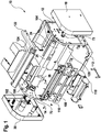
- the exploded view is shown rotated by 90 ° with respect to the position when the insert was installed in the towel dispenser 200.
- the insert 10 is connected to a rear wall 202 of a towel dispenser 200, which is covered by a swiveling hood 204 ( Fig. 8 ).
- the insert 10 has inner walls 12, 14 which are covered on the outside by cladding 18, 20.
- the inner walls 12, 14 are connected to a rear wall 112, so that the inner walls 12, 14 with the rear wall 112 form a support structure for the essential components of the towel dispenser 200.
- the rear wall 112 of the insert 10 is connected to the rear wall 202 of the towel dispenser 200, from which the hood-shaped cover 204 extends pivotably.
- the hood 204 can be pivoted about an axis 206 running in the bottom region of the rear wall 202.
- the inner walls 12, 14 with the rear wall 112 of the insert 10 can also be referred to as the inner housing.
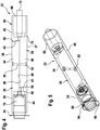
- An essential element of the invention is a pulling roller 22, which is in the Figures 4 and 5 is shown in side view or perspective illustration. Areas not visible from the outside are indicated by phantom lines.
- FIG. 3 the pulling roller 22 is shown in an exploded view, the view being compared to that shown in FIG Fig. 1 rotated by 90 °.
- the pulling roller 22 consists of two identically designed bodies 24, 26, one of which is in the Fig. 6 is shown again.
- Each body 24, 26 has an outer section 28, 60 with an outer geometry of a circular cylinder.
- the outer section 28, 60 is followed by an inner section 34, 46 which has the geometry of a circular semi-cylinder, the curved outer surface 36, 37 of which merges flush with the outer surface 44, 45 of the outer section 28, 60 designed as a hollow circular cylinder.
- bodies 24, 26 are assembled, the flat sides 38, 40 lie on top of one another, so that the geometry of a circular cylinder results on the circumferential side.
- the bodies 24, 26 can be plugged together so that simple assembly and disassembly is made possible.
- projections 48, 49, 50, 51 proceed from the end faces 42, 43 of the inner sections 34, 46, the geometrically adapted recesses 52, 53, 54, 55 in the end faces 56, 58 of the outer ones, which run vertically to the longitudinal axis of the pulling roller 22 Sections 28, 60 of bodies 24, 26 engage.
- the bodies 24, 26 can be connected to one another via a screw which penetrates a through-hole 30 provided in the inner sections 34, 46 and perpendicularly penetrates the longitudinal axis of the pulling roller 22, as is self-explanatory from the drawings.
- the outer sections 28, 60 are designed as hollow cylinders and consequently each have a cavity 64, 66 that has a cavity on the bottom has inner hollow cylindrical section 69, 70 of smaller diameter, in which ball bearings 72, 71 can be used or used.
- ball bearings 72, 71 can be used or used.
- These can be deep groove ball bearings or ring ball bearings, to name examples of embodiments.
- the pull roller 22 is mounted between the shaft 68 of an electric motor 70 and a pin or stub shaft 73, which extend in the cavities 64, 66, as in particular from the Figures 4 and 5 results.
- One end of the stub shaft 73 is mounted in the ball bearing 74, passes through the partition wall 12, and is mounted with the other end on the inside of the cover 48.
- Mounting by the shaft 68 naturally includes the technically equivalent solution that mounting takes place via an element extending from or connected to the shaft 68.
- the electric motor 70 is received in a housing 74 and is connected thereto by, for example, screws. Plug connections would also be possible.
- the receptacle housing 74 has a pot-shaped receptacle in which the electric motor 70 extends.
- the bottom 78 has a sleeve-like extension 80 through which the motor shaft 68 extends, the end region of which engages in a geometrically adapted receptacle 82 of the body 26, i.e. the outer portion 28 of which.
- the end region of the shaft 68 has a flattening and the receptacle 82 has a corresponding geometric adaptation.
- the receiving housing 74 for the electric motor 70 can be connected to the intermediate wall 14 via a single screw.
- the receiving housing 74 has a flange-like edge 84 which extends perpendicular to the longitudinal axis of the receiving housing 74.
- a screw is used which penetrates an opening 86 in the edge 84 and can be screwed into an opening 88 in the intermediate wall 14 which has an internal thread. So that a problem-free alignment with the openings 86, 88 to one another is ensured, the edge 84 has one in the plane of the Edge 84 extending projection 90 which comes to rest against a stop 92 in the outside of the partition 14.
- the openings 86, 88 are aligned with one another so that they can be screwed tight.
- the edge 84 has a further projection 94 protruding in the plane, which comes to rest against a further projection 96 in the outside of the partition 14. This ensures a simple and secure alignment between the receiving housing 74 and the partition 14.
- the sleeve-like projection 80 of the receiving housing 74 engages in an adapted opening of the ball bearing 72, which is arranged in the section 68 of the cylindrical cavity 64 of the outer section 28, so that a perfect alignment of the receiving housing 74 to the longitudinal axis of the pulling roller 22 is ensured is.
- the outer surface 76 of the receiving housing 74 runs at a distance from the inner surface 100 of the cavity 64.
- the tension roller 22 is assigned the pressure roller 25, which is subjected to force in the direction of the tension roller 22 and is mounted on a shaft 102, the bearing eyes 104, 106 of which are pivotably connected to or adjustably to the inner surfaces of the partition walls 12, 14, and thus an adjustment of the pressure roller 26 in the direction of the pulling roller 22 to ensure. This can be done by spring force.
- the pulling roller 22 rotates so that a paper section located between the pulling roller 22 and the pressure roller 26 can be conveyed and cut off in the direction of the dispensing opening of the towel dispenser.
- a cutting edge 108 is located in the exit area profile element 110, which can be plugged into the inner surfaces of the intermediate walls 12, 14.
- Holders 116 for batteries via which the electric motor 70 can be supplied with voltage, can be arranged on the rear wall 112 of the insert 10 or the support structure. Another mounting location is also possible. In the case of batteries introduced into the holder 118, these can be covered by means of a cover 120.
- a holder 122 for the electronics which is connected to a sensor, such as a capacitive sensor, in order to set the pulling roller 22 in rotation when a hand approaches the housing, thus making a paper section is issued.
- the holder 122 has an area containing the sensor and running approximately parallel to the rear wall 202 of the towel dispenser 200 in the drawing, which is covered towards the outside, for example by a window in the hood 204.
- a rocker 124 is provided, by means of which paper is pressed against the tension roller 22 for threading into the gap between the driven tension roller 22 and pressure roller 25.
- the inner wall 154 forming an element of the insert 10 according to FIG Fig. 9 which can replace the inner wall 14, has in its outer side 156 to be closed by the cover 20 also an opening 55, which is from that of the Fig. 10 to be removed receiving housing 174 is penetrated, which is determined according to the receiving housing 74 for receiving the electric motor 70 and corresponds to the structure and function of the receiving housing 74, so among other things also a perpendicular to the longitudinal axis of the receiving housing 74 extending flange-like edge 184 with an in the plane extending projection 190 which, in the variant provided, engages in a receptacle 192 protruding in the area of opening 55 when the receptacle housing 174 is properly positioned in order to clearly align the receptacle housing 174 with a screw opening extending in the inner wall 154 ensure to connect the receiving housing 174 to the inner wall 154.
- the receptacle 192 has a slot 196 into which the projection 190 can penetrate.
- the flange-like edge 184 is made thicker than the wall thickness of the receiving housing 174.
- the inner wall 154 also has a V-shaped recess 198 in the upper edge in order to insert a replacement paper roll.
- Fig. 11 an alternative embodiment of a body 224 is shown, the function of which corresponds to that of the body 24, which forms the pulling roller 22 with a corresponding further body.
- the body 224 differs from the body 24 in that the outer surface of the outer section 260 does not merge in alignment with the outer surface 246 of the inner section of the body 224, but instead a region 266 of smaller diameter runs between these, so that each step extends to the Outer surfaces of the outer portion 260 and the inner portion 264 results.
- a rubber band or a similarly acting element generating static friction can then be introduced into this set-back intermediate space 266 in order to pull a paper section through the gap running between the pulling roller 22 and the pressure roller 25.
- the outer diameter of the outer section 260 is smaller than the diameter of the cylinder, which results with appropriately assembled bodies to form the pulling roller 22 in relation to the inner section 264.
- the further body to be plugged together with the body 224 in addition to the pulling roller 22 has a geometry which corresponds to the body 224, as has been explained in connection with the bodies 24 and 26.
- the essential components can be connected by plug-in connections, so that problem-free assembly is made possible.
- the pulling roller 22 is precisely supported without the need for a high level of structural complexity.
- the identically designed bodies 24, 26, which form the pulling roller 22, result in manufacturing advantages.
Abstract
Die Erfindung bezieht sich auf einen Handtuchspender umfassend ein Gehäuse, eine erste und eine zweite innere Halteeinrichtung (12, 14), eine Zugrolle (22), eine in Richtung der Zugrolle kraftbeaufschlagte Druckrolle (25) sowie einen die Zugrolle in Drehbewegung versetzenden Motor (70) mit Motorwelle (68) zum Transportieren eines Abschnitts des Handtuchs zwischen der Zugrolle und der Druckrolle. Die Zugrolle (22) weist zumindest in einem ihrer Endbereiche einen endseitig offenen Hohlraum (64) auf, in dem der Motor (70) angeordnet ist, und dass die Zugrolle zwischen der Motorwelle (68) und einem von einer der inneren Halteeinrichtungen (12) ausgehenden oder diesen durchsetzenden Wellenstumpf (73) gelagert ist.

Description
Die Erfindung bezieht sich auf einen Handtuchspender umfassend ein Gehäuse, eine erste und eine zweite innere Halteeinrichtung, wie Innenwandung, eine Zugrolle, eine in Richtung der Zugrolle kraftbeaufschlagte Druckrolle sowie einen die Zugrolle in Drehbewegung versetzenden Motor mit Motorwelle zum Transportieren eines Abschnitts des Handtuchs, wie Papierbahn, zwischen der Zugrolle und der Druckrolle, wobei der Motor in einem endseitig offenen Hohlraum der Zugrolle angeordnet ist.The invention relates to a towel dispenser comprising a housing, a first and a second inner holding device, such as an inner wall, a pulling roller, a pressure roller acted upon by force in the direction of the pulling roller and a motor with a motor shaft that sets the pulling roller in rotation for transporting a section of the towel, such as Paper web, between the tension roller and the pressure roller, the motor being arranged in a cavity of the tension roller which is open at the end.
Der
Ein Handtuchspender für Rollenhandtücher ist aus der
Aus der
Bei einem Papierspender nach der
Der vorliegenden Erfindung liegt die Aufgabe zugrunde, einen Handtuchspender der eingangs genannten Art derart weiterzubilden, dass ein konstruktiv einfacher und wartungsarmer Aufbau gegeben ist. Ein problemloser Zusammenbau auch von ungeschulten Personen soll möglich sein.The present invention is based on the object of developing a towel dispenser of the type mentioned at the outset in such a way that a structurally simple and low-maintenance structure is provided. A problem-free assembly even by untrained people should be possible.
Zur Lösung der Aufgabe sieht die Erfindung im Wesentlichen vor, dass die Zugrolle zumindest in einem ihrer Endbereiche einen endseitig offenen Hohlraum aufweist, in dem der Motor angeordnet ist, und dass die Zugrolle zwischen der Motorwelle oder einem von dieser ausgehenden Element und einem von einer der inneren Halteeinrichtungen ausgehenden oder diese durchsetzenden Wellenstumpf gelagert ist.To achieve the object, the invention essentially provides that the pulling roller has, at least in one of its end regions, a cavity open at the end, in which the motor is arranged, and that the pulling roller is between the motor shaft or an element extending therefrom and one of the inner holding devices outgoing or these penetrating stub shaft is supported.
Über quasi Steckverbindungen kann die Zugrolle gelagert werden. Der Motor kann problemlos ausgetauscht und durch einen neuen ersetzt werden, ohne dass ein aufwendiges Auseinanderbauen des Handtuchspenders erforderlich ist.The pulley can be stored using plug-in connections, so to speak. The motor can easily be exchanged and replaced with a new one, without the need for time-consuming disassembly of the towel dispenser.
Eine konstruktive Vereinfachung ergibt sich insbesondere auch dadurch, dass die Zugrolle aus zwei gleich ausgebildeten lösbar miteinander verbundenen Körpern besteht.A structural simplification also results in particular from the fact that the pulling roller consists of two identically designed bodies that are releasably connected to one another.
Dabei ist hervorzuheben, dass die Körper jeweils aus einem den Hohlraum umgebenen äußeren Hohlzylinderabschnitt und einem von diesem ausgehenden und in dessen Längsrichtung verlaufenden inneren Abschnitt in Form einer Zylinderhälfte besteht, wobei bei zusammengesetzten Körpern die Zylinderhälften mit ihren in Zylinderlängsachsenrichtung verlaufende Flachseiten aufeinanderliegen und Umfangsfläche des einen Körpers fluchtend in Umfangsfläche des anderen Körpers übergeht oder die Umfangsflächen parallel zueinander versetzt zur Bildung einer umlaufenden Senke wie Nut verlaufen.It should be emphasized that the bodies each consist of an outer hollow cylinder section surrounding the cavity and an inner section in the form of a cylinder half extending therefrom and running in its longitudinal direction, with the cylinder halves lying on top of one another with their flat sides running in the longitudinal direction of the cylinder axis and the circumferential surface of the one Body passes over in alignment with the circumferential surface of the other body or the circumferential surfaces run parallel to one another offset to form a circumferential depression such as a groove.
Jeder Körper besteht demzufolge aus einem äußeren Abschnitt, der eine Hohlzylindergeometrie aufweist, an den sich der innere Abschnitt anschließt, der aus einem in Längsrichtung geteilten Zylinder besteht, wobei die in Längsrichtung des Zylinders verlaufenden Flachseiten der Körper aufeinanderliegen.Each body accordingly consists of an outer section which has a hollow cylinder geometry, to which the inner section adjoins, which consists of a cylinder divided in the longitudinal direction, the flat sides of the body extending in the longitudinal direction of the cylinder lying on top of one another.
Bei zusammengesetzten Körpern steht ein Kreiszylinder zur Verfügung, wobei die Körper vorzugsweise durch Steckverbindungen miteinander verbunden sind. Hierzu ist insbesondere vorgesehen, dass zum Zusammenstecken der Körper diese in ihren zueinander auszurichtenden Stirnflächen des ersten und des zweiten Abschnitts Vorsprünge und korrespondierende Aussparungen aufweisen.In the case of assembled bodies, a circular cylinder is available, the bodies preferably being connected to one another by plug connections. For this purpose, it is provided in particular that, in order to plug the bodies together, they have projections and corresponding recesses in their end faces of the first and second sections that are to be aligned with one another.
Um eine einfache Ausrichtung des Motors zur Innenwandung des Hohlraums zu ermöglichen, ist vorgesehen, dass der Motor von einem Aufnahmegehäuse aufgenommen ist, das von der weiteren inneren Haltereinrichtung ausgeht, dass sich das Aufnahmegehäuse innerhalb des Hohlraums und beabstandet zu dessen Innenwandung erstreckt und über ein in dem Körper angeordnetes erstes Kugellager gegenüber der Zugrolle abgestützt ist.In order to enable a simple alignment of the motor to the inner wall of the cavity, it is provided that the motor is received by a receiving housing which extends from the further inner holder device, that the receiving housing extends within the cavity and at a distance from its inner wall and via an in the first ball bearing arranged on the body is supported against the pulling roller.
Die Motorwelle durchsetzt folglich die Bodenwandung des Aufnahmegehäuses, um in eine entsprechende Aussparung in der Bodenwandung im Hohlraum des Körpers einzugreifen und somit eine Rotation der Zugrolle zu ermöglichen. Das Ansteuern des Motors kann dabei über eine Elektronik sowie einen Sensor erfolgen, wie diese in der
Der Wellenstumpf selbst ist über ein zweites Kugellager gegenüber der Zugrolle abgestützt. Das zweite Kugellager - wie das erste Kugellager - erstrecken sich dabei vorzugsweise jeweils entlang der Bodenwandung des Hohlraums des äußeren Hohlzylinderabschnitts.The stub shaft itself is supported by a second ball bearing opposite the pulling roller. The second ball bearing - like the first ball bearing - preferably each extend along the bottom wall of the cavity of the outer hollow cylinder section.
Um eine einfache Befestigung des Aufnahmegehäuses für den Elektromotor an der Halteeinrichtung, die insbesondere eine Innenwandung des Handtuchspenders ist, zu ermöglichen, sieht die Erfindung vor, dass das Aufnahmegehäuse öffnungsseitig einen senkrecht zur Längsachse des Aufnahmegehäuses verlaufenden flanschartigen Rand aufweist, der bei montiertem Aufnahmegehäuse an zungenrollenabgewandter Außenseite der weiteren inneren Halteeinrichtung anliegt.In order to enable simple attachment of the housing for the electric motor to the holding device, which is in particular an inner wall of the towel dispenser, the invention provides that the housing has a flange-like edge on the opening side that runs perpendicular to the longitudinal axis of the housing and which, when the housing is installed, faces away from the tongue roll Outside of the further inner holding device rests.
Dabei kann der flanschartige Rand eine in der Ebene des Randes sich erstreckende Unstetigkeit, wie Vorsprung, aufweisen, der bei ordnungsgemäßer Ausrichtung des Aufnahmegehäuses zu der Halteeinrichtung mit einem von diesem abragenden Anschlag wechselwirkt. Hierdurch wird gleichzeitig sichergestellt, dass eine Durchgangsöffnung in dem Rand des Aufnahmegehäuses auf eine ein Innengewinde aufweisende Öffnung der Halteeinrichtung ausgerichtet ist, um das Gehäuse befestigen zu können.The flange-like edge can have a discontinuity, such as a projection, which extends in the plane of the edge and interacts with a stop protruding therefrom when the receiving housing is properly aligned with the holding device. This at the same time ensures that a through opening in the edge of the receiving housing is aligned with an opening of the holding device having an internal thread in order to be able to fasten the housing.
Die Oberfläche der Zugrolle kann z.B. zumindest bereichsweise strukturiert, wie aufgeraut, sein oder zumindest bereichsweise eine Beschichtung aufweisen, um das Handtuch durch den Spalt zwischen der Zug- und Druckrolle bei sich drehender Zugrolle zu transportieren. Auch besteht die Möglichkeit, die auf die zu dem Zylinderkörper zusammengesetzten und die Zugrolle bildenden Körper eine Umhüllende, wie einen Schrumpfschlauch, aufzuziehen, der die erforderliche Haftreibung zum Transport des Handtuchs sicherstellt.The surface of the pulling roller can, for example, at least partially be structured, such as roughened, or at least partially have a coating in order to transport the towel through the gap between the pulling and pressure roller when the pulling roller is rotating. There is also the possibility of pulling an envelope, such as a shrink tube, onto the body, which is assembled to form the cylinder body and forms the pulling roller, which ensures the required static friction for transporting the towel.
Alternativ oder ergänzend ist vorgesehen, dass bei zusammengesetzten Körpern zwischen den inneren und äußeren Abschnitten eine umlaufende Vertiefung, wie Nut, verläuft, in die ein eine Haftreibung für zu transportierendes Papier erzeugendes Element, wie Gummiband oder -ring, eingebracht ist.As an alternative or in addition, it is provided that when the bodies are assembled, a circumferential recess, such as a groove, runs between the inner and outer sections, into which an element such as a rubber band or ring, which generates static friction for the paper to be transported, is introduced.
Insbesondere bezieht sich die Erfindung auf einen Handtuchspender umfassend ein Gehäuse, eine erste und eine zweite innere Halteeinrichtung, wie Innenwandung, eine Zugrolle, eine in Richtung der Zugrolle kraftbeaufschlagte Druckrolle sowie einen die Zugrolle in Drehbewegung versetzenden Motor mit Motorwelle zum Transportieren eines Abschnitts des Handtuchs zwischen der Zugrolle und der Druckrolle, wobei der Motor in einem endseitig offenen Hohlraum der Zugrolle angeordnet ist, wobei sich der Handtuchspender dadurch auszeichnet, dass die Zugrolle zwischen der Motorwelle und einem von einer der inneren Halteeinrichtungen ausgehenden oder diesen durchsetzenden Wellenstumpf gelagert ist, dass der Motor von einem Aufnahmegehäuse aufgenommen ist, das von einer der inneren Haltereinrichtungen ausgeht, dass sich das Aufnahmegehäuse innerhalb des Hohlraums und beabstandet zu dessen Innenwandung erstreckt und über ein in dem Körper angeordnetes erstes Kugellager gegenüber der Zugrolle abgestützt ist, und dass der Wellenstumpf über ein in dem Körper angeordnetes zweites Kugellager gegenüber der Zugrolle abgestützt ist.In particular, the invention relates to a towel dispenser comprising a housing, a first and a second inner holding device, such as an inner wall, a pulling roller, a pressure roller acted upon by force in the direction of the pulling roller and a motor with a motor shaft which sets the pulling roller in rotation for transporting a section of the towel between the pull roller and the pressure roller, the motor being arranged in a cavity of the pull roller which is open at the end, the towel dispenser being characterized in that the pull roller is mounted between the motor shaft and a stub shaft extending from or penetrating one of the inner holding devices, that the motor is received by a receiving housing which proceeds from one of the inner holder devices, that the receiving housing extends within the cavity and at a distance from its inner wall and is supported by a first ball bearing arranged in the body with respect to the pulling roller and that the stub shaft is supported with respect to the pulling roller via a second ball bearing arranged in the body.
Gegenstand der Erfindung ist auch ein Handtuchspender umfassend ein Gehäuse, eine erste und eine zweite innere Halteeinrichtung, wie Innenwandung, eine Zugrolle, eine in Richtung der Zugrolle kraftbeaufschlagte Druckrolle sowie einen die Zugrolle in Drehbewegung versetzenden Motor mit Motorwelle zum Transportieren eines Abschnitts des Handtuchs zwischen der Zugrolle und der Druckrolle, wobei der Motor in einem endseitig offenen Hohlraum der Zugrolle angeordnet ist, wobei sich der Handtuchspender dadurch auszeichnet, dass die Zugrolle zwischen der Motorwelle und einem von einer der inneren Halteeinrichtungen ausgehenden oder diesen durchsetzenden Wellenstumpf gelagert ist, dass die Zugrolle aus zwei gleich ausgebildeten lösbar miteinander verbundenen Körpern besteht, dass die Körper jeweils aus einem den Hohlraum umgebenen äußeren Hohlzylinderabschnitt und einem von diesem ausgehenden und in dessen Längsrichtung verlaufenden inneren Abschnitt in Form einer Zylinderhälfte bestehen, wobei bei zusammengesetzten Körpern die Zylinderhälften mit ihren in Zylinderlängsachsenrichtung verlaufende Flachseiten aufeinanderliegen und Umfangsfläche des einen Körpers fluchtend in Umfangsfläche des anderen Körpers übergeht oder die Umfangsflächen parallel zueinander versetzt zur Bildung einer umlaufenden Senke verlaufen.The invention also relates to a towel dispenser comprising a housing, a first and a second inner holding device, such as an inner wall, a pulling roller, a pressure roller acted upon by force in the direction of the pulling roller and a motor with a motor shaft that sets the pulling roller in rotation for transporting a section of the towel between the Pull roller and the pressure roller, the motor being arranged in a cavity of the pull roller that is open at the end, the towel dispenser being characterized in that the pull roller is mounted between the motor shaft and a stub shaft extending from or penetrating one of the inner holding devices two identically designed detachably interconnected bodies, that the bodies each consist of an outer hollow cylinder section surrounding the cavity and an inner section in the form of a cylinder half extending therefrom and extending in its longitudinal direction, wherein In the case of composite bodies, the cylinder halves lie on top of one another with their flat sides running in the longitudinal axis direction of the cylinder and the circumferential surface of one body merges flush with the circumferential surface of the other body or the circumferential surfaces are offset parallel to one another to form a circumferential depression.
Weitere Einzelheiten, Vorteile und Merkmale der Erfindung ergeben sich nicht nur aus den Ansprüchen, den diesen zu entnehmenden Merkmalen - für sich und/oder in Kombination -, sondern auch aus der nachfolgenden Beschreibung eines der Zeichnungen zu entnehmenden bevorzugten Ausführungsbeispiels.Further details, advantages and features of the invention emerge not only from the claims, the features to be taken from them - individually and / or in combination - but also from the following description of a preferred embodiment shown in the drawings.
Es zeigen:
- Fig. 1
- eine Explosionsdarstellung eines Einsatzes eines Handtuchspenders, um 90° gegenüber der Nutzstellung gedreht,
- Fig. 2
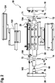
- eine weitere Explosionsdarstellung des Einsatzes des Handtuchspenders,
- Fig. 3
- eine Explosionsdarstellung einer Zugrolle des Handtuchspenders,
- Fig. 4
- eine erste Darstellung einer zusammengesetzten Zugrolle,
- Fig. 5
- eine zweite Darstellung einer zusammengesetzten Zugrolle,
- Fig. 6
- eine Darstellung eines Körpers der Zugrolle,
- Fig. 7
- ein Gehäuse für einen Elektromotor,
- Fig. 8
- einen Handtuchspender in Seitenansicht und aufgeklappt,
- Fig. 9
- eine Innenwandung des Handtuchspenders,
- Fig. 10
- ein Aufnahmegehäuse für einen Motor und
- Fig. 11
- einen Körper einer Zugrolle.
- Fig. 1
- an exploded view of an insert of a towel dispenser, rotated by 90 ° with respect to the use position,
- Fig. 2
- another exploded view of the use of the towel dispenser,
- Fig. 3
- an exploded view of a pull roller of the towel dispenser,
- Fig. 4
- a first representation of an assembled pulling pulley,
- Fig. 5
- a second representation of an assembled pulling pulley,
- Fig. 6
- a representation of a body of the pulling roller,
- Fig. 7
- a housing for an electric motor,
- Fig. 8
- a towel dispenser in side view and unfolded,
- Fig. 9
- an inner wall of the towel dispenser,
- Fig. 10
- a housing for a motor and
- Fig. 11
- a body of a pulley.
In den
Die Explosionsdarstellung ist um 90° gedreht gegenüber der Position beim Einbau des Einsatzes in den Handtuchspender 200 wiedergegeben.The exploded view is shown rotated by 90 ° with respect to the position when the insert was installed in the
Der Einsatz 10 wird mit einer Rückwandung 202 eines Handtuchspenders 200 verbunden, der von einer schwenkbaren Haube 204 abgedeckt ist (
Der Einsatz 10 weist Innenwandungen 12, 14 auf, die außenseitig von Verkleidungen 18, 20 abgedeckt sind. Die Innenwandungen 12, 14 sind mit einer Rückwandung 112 verbunden, so dass die Innenwandungen 12, 14 mit der Rückwandung 112 eine Tragstruktur für die wesentlichen Bauelemente des Handtuchspenders 200 bilden. Die Rückwandung 112 des Einsatzes 10 ist mit der Rückwandung 202 des Handtuchspenders 200 verbunden, von der verschwenkbar die haubenförmige Abdeckung 204 ausgeht. Die Haube 204 ist um eine im Bodenbereich der Rückwandung 202 verlaufende Achse 206 schwenkbar.The
Wie sich aus der
Die Innenwandungen 12, 14 mit der Rückwandung 112 des Einsatzes 10 können auch als Innengehäuse bezeichnet werden.The
Wesentliches Element der Erfindung ist eine Zugrolle 22, die in den
In der
Die Zugrolle 22 besteht aus zwei identisch ausgebildeten Körpern 24, 26, von denen einer in der
Die Körper 24, 26 können zusammengesteckt sein, so dass eine einfache Montage und Demontage ermöglicht wird. Hierzu gehen von den Stirnflächen 42, 43 der inneren Abschnitte 34, 46 Vorsprünge 48, 49, 50, 51 aus, die geometrisch angepasste Aussparungen 52, 53, 54, 55 in den vertikal zur Längsachse der Zugrolle 22 verlaufenden Stirnflächen 56, 58 der äußeren Abschnitte 28, 60 der Körper 24, 26 eingreifen. Zusätzlich können die Körper 24, 26 über eine Schraube miteinander verbunden werden, die eine Durchgangsbohrung 30 durchsetzt, die in den inneren Abschnitten 34, 46 vorgesehen ist, und senkrecht die Längsachse der Zugrolle 22 durchsetzt, wie sich aus den zeichnerischen Darstellungen selbsterklärend ergibt.The
Wie die Figuren verdeutlichen, sind die äußeren Abschnitte 28, 60 als Hohlzylinder ausgebildet und weisen folglich jeweils einen Hohlraum 64, 66 auf, der bodenseitig einen inneren hohlzylindrischen Abschnitt 69, 70 kleineren Durchmessers aufweist, in denen Kugellager 72, 71 einsetzbar bzw. eingesetzt sind. Hierbei kann es sich um Rillenkugellager oder Ringkugellager handeln, um beispielhaft Ausführungsformen zu nennen.As the figures make clear, the
Die Zugrolle 22 wird zwischen der Welle 68 eines Elektromotors 70 und einem Zapfen bzw. Wellenstumpf 73 gelagert, die sich in den Hohlräumen 64, 66 erstrecken, wie sich insbesondere aus den
Lagerung durch die Welle 68 schließt selbstverständlich die technisch gleichwirkende Lösung ein, dass eine Lagerung über ein von der Welle 68 ausgehendes bzw. mit diesem verbundenes Element erfolgt.Mounting by the
Der Elektromotor 70 wird von einem Aufnahmegehäuse 74 aufgenommen und ist z.B. durch Schrauben mit diesem verbunden. Auch Steckverbindungen wären möglich.The
Das Aufnahmegehäuse 74 weist eine topfförmige Aufnahme auf, in der sich der Elektromotor 70 erstreckt. Der Boden 78 besitzt einen hülsenartigen Fortsatz 80, durch den sich die Motorwelle 68 erstreckt, deren Endbereich in eine geometrisch angepasste Aufnahme 82 des Körpers 26, d.h., dessen äußeren Abschnitt 28 eingreift.The
Damit die Drehbewegung der Motorwelle 68 auf die Zugrolle 22 übertragen wird, weist der Endbereich der Welle 68 eine Abflachung und die Aufnahme 82 eine entsprechende geometrische Anpassung auf.So that the rotary movement of the
Das Aufnahmegehäuse 74 für den Elektromotor 70 kann über eine einzige Schraube mit der Zwischenwandung 14 verbunden sein. Hierzu weist das Aufnahmegehäuse 74 einen flanschartigen Rand 84 auf, der sich senkrecht zur Längsachse des Aufnahmegehäuses 74 erstreckt. Zum Befestigen wird eine Schraube benutzt, die eine Öffnung 86 in dem Rand 84 durchsetzt und in eine ein Innengewinde aufweisende Öffnung 88 in der Zwischenwandung 14 einschraubbar ist. Damit eine problemlose Ausrichtung zu den Öffnungen 86, 88 zueinander sichergestellt ist, weist der Rand 84 einen in der Ebene des Randes 84 verlaufenden Vorsprung 90 auf, der gegen einen Anschlag 92 in der Außenseite der Zwischenwandung 14 zum Anliegen kommt. In dieser Position sind die Öffnungen 86, 88 fluchtend zueinander ausgerichtet, so dass ein Festschrauben erfolgen kann. Im Bereich der Öffnung 88 weist der Rand 84 einen weiteren in der Ebene abragenden Vorsprung 94 auf, der gegen einen weiteren Vorsprung 96 in der Außenseite der Zwischenwandung 14 zum Anliegen kommt. Hierdurch ist eine einfache und sichere Ausrichtung zwischen dem Aufnahmegehäuse 74 und der Zwischenwandung 14 sichergestellt.The receiving
Der hülsenartige Vorsprung 80 des Aufnahmegehäuses 74 greift in eine angepasste Öffnung des Kugellagers 72 ein, das in dem Abschnitt 68 des eine Zylinderform aufweisenden Hohlraums 64 des äußeren Abschnitts 28 angeordnet ist, so dass eine einwandfreie Ausrichtung des Aufnahmegehäuses 74 zu der Längsachse der Zugrolle 22 gewährleistet ist. Dabei verläuft die Außenfläche 76 des Aufnahmegehäuses 74 beabstandet zur Innenfläche 100 des Hohlraums 64.The sleeve-
Somit ist gewährleistet, dass Längsachse der Motorwelle 68, Längsachse des Zapfens oder Wellenstumpfes 73 und Längsachse der Zugrolle 22 entlang einer gemeinsamen Geraden verlaufen und das Aufnahmegehäuse 74 die Rotation der Zugrolle 22 nicht behindern kann.This ensures that the longitudinal axis of the
Der Zugrolle 22 ist die in Richtung der Zugrolle 22 kraftbeaufschlagte Druckrolle 25 zugeordnet, die auf einer Welle 102 gelagert ist, deren Lageraugen 104, 106 schwenkbar mit bzw. verstellbar zu den Innenflächen der Zwischenwandungen 12, 14 verbunden ist, und somit ein Verstellen der Druckrolle 26 in Richtung der Zugrolle 22 sicherzustellen. Dies kann durch Federkraft erfolgen.The
Wird durch Annäherung an den nicht dargestellten Sensor der Motor 70 betätigt, so dreht sich die Zugrolle 22, so dass ein zwischen der Zugrolle 22 und der Druckrolle 26 befindlicher Papierabschnitt in Richtung der Ausgabeöffnung des Handtuchspenders gefördert und abgetrennt werden kann. Hierzu befindet sich im Ausgangsbereich ein eine Schneidkante 108 befindliches Profilelement 110, das steckbar mit den Innenflächen der Zwischenwandungen 12, 14 verbindbar ist.If the
Auf die Rückwandung 112 des Einsatzes 10 bzw. der Tragstruktur können Halterungen 116 für Batterien angeordnete sein, über die der Elektromotor 70 mit Spannung versorgbar ist. Ein anderer Befestigungsort ist gleichfalls möglich. Bei in die Halterung 118 eingebrachten Batterien sind diese mittels einer Abdeckung 120 abdeckbar.Holders 116 for batteries, via which the
Im haubenseitig verlaufenden Bereich des Einsatzes 10 ist eine Halterung 122 für die Elektronik vorhanden, die mit einem Sensor, wie kapazitiven Sensor, verbunden ist, um dann, wenn sich eine Hand dem Gehäuse nähert, die Zugrolle 22 in Drehbewegung zu versetzen, damit ein Papierabschnitt ausgegeben wird.In the area of the
Wie sich aus der
Ferner ist eine Wippe 124 vorgesehen, mittels der Papier zum Einfädeln in den Spalt zwischen der angetriebenen Zugrolle 22 und Druckrolle 25 gegen die Zugrolle 22 gedrückt wird.Furthermore, a
Den
Die ein Element des Einsatzes 10 bildende Innenwandung 154 gemäß
Um eine hinreichende Stabilität zu erzielen, ist der flanschartige Rand 184 im Vergleich zur Wandstärke des Aufnahmegehäuses 174 dicker ausgebildet.In order to achieve sufficient stability, the flange-
Wie die Innenwandung 14 weist auch die Innenwandung 154 im oberen Rand eine V-förmig gebildete Aussparung 198 auf, um eine Ersatzpapierrolle einzusetzen.Like the
In
Der Körper 224 unterscheidet sich von dem Körper 24 dahingehend, dass die Außenfläche des äußeren Abschnitts 260 nicht fluchtend in die Außenfläche 246 des inneren Abschnitts des Körpers 224 übergeht, sondern zwischen diesen ein Bereich 266 geringeren Durchmessers verläuft, so dass sich jeweils eine Stufe zu den Außenflächen des äußeren Abschnitts 260 bzw. des inneren Abschnitts 264 ergibt.The
In diesen zurückversetzten Zwischenraum 266 kann sodann ein Gummiband oder ähnlich wirkendes eine Haftreibung erzeugendes Element eingebracht werden, um einen Papierabschnitt durch den zwischen der Zugrolle 22 und der Druckrolle 25 verlaufenden Spalt zu ziehen.A rubber band or a similarly acting element generating static friction can then be introduced into this set-back
Der Außendurchmesser des äußeren Abschnitts 260 ist dabei kleiner als der Durchmesser des Zylinders, der sich bei entsprechend zusammengesetzten Körpern zur Bildung der Zugrolle 22 in Bezug auf den inneren Abschnitt 264 ergibt. Der zu der Zugrolle 22 ergänzend mit dem Körper 224 zusammenzusteckende weitere Körper weist entsprechend der erfindungsgemäßen Lehre eine Geometrie auf, die dem Körper 224 entspricht, wie dies im Zusammenhang mit den Körpern 24 und 26 erläutert worden ist.The outer diameter of the
Wie sich insbesondere aus den Figuren und der erfolgten Beschreibung ergibt, sind die wesentlichen Bauteile durch Steckverbindungen verbindbar, so dass eine problemlose Montage ermöglicht wird.As can be seen in particular from the figures and the description that has taken place, the essential components can be connected by plug-in connections, so that problem-free assembly is made possible.
Die Zugrolle 22 ist präzise gelagert, ohne dass es eines hohen konstruktiven Aufwands bedarf.The pulling
Durch die identisch ausgebildeten Körper 24, 26, die die Zugrolle 22 bilden, ergeben sich herstellungstechnisch Vorteile.The identically designed
Claims (11)
dadurch gekennzeichnet,
dass die Zugrolle zwischen der Motorwelle (68) oder einem von dieser ausgehenden Element und einem von einer der inneren Halteeinrichtungen (12) ausgehenden oder diese durchsetzenden Wellenstumpf (73) gelagert ist.Towel dispenser (200) comprising a housing, a first and a second inner holding device (12, 14, 154), such as an inner wall, a pulling roller (22), a pressure roller (25) acted upon by force in the direction of the pulling roller and a motor which sets the pulling roller in rotation (70) with a motor shaft (68) for transporting a section of the towel between the pull roller and the pressure roller, the motor being arranged in a cavity (64) of the pull roller which is open at the end,
characterized,
that the pulling roller is mounted between the motor shaft (68) or an element extending from it and a stub shaft (73) extending from or penetrating one of the inner holding devices (12).
dadurch gekennzeichnet,
dass die Zugrolle (22) aus zwei gleich ausgebildeten lösbar miteinander verbundenen Körpern (24, 26, 224) besteht.Towel dispenser according to claim 1,
characterized,
that the pulling roller (22) consists of two identically designed releasably connected bodies (24, 26, 224).
dadurch gekennzeichnet,
dass die Körper (24, 26, 224) jeweils aus einem den Hohlraum (64, 66) umgebenen äußeren Hohlzylinderabschnitt (28, 60, 260) und einem von diesem ausgehenden und in dessen Längsrichtung verlaufenden inneren Abschnitt (34, 46, 264) in Form einer Zylinderhälfte besteht, wobei bei zusammengesetzten Körpern die Zylinderhälften mit ihren in Zylinderlängsachsenrichtung verlaufende Flachseiten (38, 40) aufeinanderliegen und Umfangsfläche des einen Körpers fluchtend in Umfangsfläche des anderen Körpers übergeht oder die Umfangsflächen parallel zueinander versetzt zur Bildung einer umlaufenden Senke, wie Nut (226), verlaufen.Towel dispenser according to claim 1 or 2,
characterized,
that the bodies (24, 26, 224) each consist of an outer hollow cylinder section (28, 60, 260) surrounding the cavity (64, 66) and an inner section (34, 46, 264) extending therefrom and extending in the longitudinal direction thereof Shape of a cylinder half, with the cylinder halves in assembled bodies with their flat sides (38, 40) running in the longitudinal axis direction of the cylinder lying on top of one another and the circumferential surface of one body merges into the circumferential surface of the other body in alignment or the circumferential surfaces are parallel offset from one another to form a circumferential depression, such as a groove (226).
dadurch gekennzeichnet,
dass zum Zusammenstecken der Körper (24, 26, 224) diese in ihren zueinander auszurichtenden Stirnflächen (42, 44, 56, 58) des inneren und des äußeren Abschnitts (34, 46; 28, 60; 260, 264) Vorsprünge (48, 49, 50, 51) und korrespondierende Aussparungen (52, 53, 54, 55) aufweisen.Towel dispenser according to at least one of the preceding claims,
characterized,
that in order to plug the bodies (24, 26, 224) together they have projections (48, 48, 49, 50, 51) and corresponding recesses (52, 53, 54, 55).
dadurch gekennzeichnet,
dass der Motor (70) von einem Aufnahmegehäuse (74, 274) aufgenommen ist, das von der weiteren inneren Haltereinrichtung (14) ausgeht, dass sich das Aufnahmegehäuse innerhalb des Hohlraums (64) und beabstandet zu dessen Innenwandung (100) erstreckt und über ein in dem Körper (26) angeordnetes erstes Kugellager (72) gegenüber der Zugrolle (22) abgestützt ist.Towel dispenser according to at least one of the preceding claims,
characterized,
that the motor (70) is received by a receiving housing (74, 274) which extends from the further inner holder device (14), that the receiving housing extends within the cavity (64) and at a distance from its inner wall (100) and over a in the body (26) arranged first ball bearing (72) is supported opposite the pulling roller (22).
dadurch gekennzeichnet,
dass der Wellenstumpf (73) über ein in dem Körper (24) angeordnetes zweites Kugellager (71) gegenüber der Zugrolle (22) abgestützt ist.Towel dispenser according to at least one of the preceding claims,
characterized,
that the stub shaft (73) is supported against the pulling roller (22) via a second ball bearing (71) arranged in the body (24).
dadurch gekennzeichnet,
dass sich das erste und/oder das zweite Kugellager (71, 72) entlang Bodenwandung des Hohlraums (64, 66) erstreckt.Towel dispenser according to at least one of the preceding claims,
characterized,
that the first and / or the second ball bearing (71, 72) extends along the bottom wall of the cavity (64, 66).
dadurch gekennzeichnet,
dass das Aufnahmegehäuse (74, 274) öffnungsseitig einen senkrecht zur Längsachse des Aufnahmegehäuses verlaufenden flanschartigen Rand (84) aufweist, der bei montiertem Aufnahmegehäuse an zungenrollenabgewandter Außenseite der weiteren inneren Halteeinrichtung (14) anliegt.Towel dispenser according to at least one of the preceding claims,
characterized,
that the receiving housing (74, 274) on the opening side has a flange-like edge (84) which runs perpendicular to the longitudinal axis of the receiving housing and which, when the receiving housing is mounted, rests on the outside of the further inner holding device (14) facing away from the tongue roller.
dadurch gekennzeichnet,
dass Oberfläche der Zugrolle (22) zumindest bereichsweise strukturiert, wie aufgeraut und/oder beschichtet, oder von einer eine Haftreibung ermöglichenden Umhüllenden umgeben ist.Towel dispenser according to at least one of the preceding claims,
characterized,
that the surface of the tension roller (22) is at least partially structured, such as roughened and / or coated, or is surrounded by an envelope that enables static friction.
dadurch gekennzeichnet,
dass das Aufnahmegehäuse (74) bodenseitig einen hülsenartigen Vorsprung (80) aufweist, der von der Motorwelle (68) durchsetzt ist und seinerseits bei montierter Zugrolle (22) in eine mittig von Längsachse der Zugrolle durchsetzte Aufnahme, wie Öffnung (80), eingreift und koaxial die Längsachse umgibt.Towel dispenser according to at least one of the preceding claims,
characterized,
that the receiving housing (74) has a sleeve-like projection (80) at the bottom through which the motor shaft (68) passes and, when the pulling roller (22) is mounted, engages in a receptacle, such as an opening (80), penetrated centrally by the longitudinal axis of the pulling roller, and surrounds the longitudinal axis coaxially.
dadurch gekennzeichnet,
dass bei zusammengesetzten Körpern (24, 26, 224) zwischen deren inneren und äußeren Abschnitten (34, 46, 28, 60, 246, 260) eine umlaufende Vertiefung (266), wie Nut, verläuft, in die ein eine Haftreibung für zu transportierendes Papier erzeugendes Element, wie Gummiband oder -ring, eingebracht ist.Towel dispenser according to at least one of the preceding claims,
characterized,
that in the case of assembled bodies (24, 26, 224) between their inner and outer sections (34, 46, 28, 60, 246, 260) a circumferential recess (266), such as a groove, runs into which a static friction for the to be transported Paper-producing element, such as rubber band or ring, is introduced.
Applications Claiming Priority (1)
| Application Number | Priority Date | Filing Date | Title |
|---|---|---|---|
| DE102020116995.7A DE102020116995A1 (en) | 2020-06-29 | 2020-06-29 | Towel dispenser |
Publications (1)
| Publication Number | Publication Date |
|---|---|
| EP3932275A1 true EP3932275A1 (en) | 2022-01-05 |
Family
ID=76250078
Family Applications (1)
| Application Number | Title | Priority Date | Filing Date |
|---|---|---|---|
| EP21177131.6A Pending EP3932275A1 (en) | 2020-06-29 | 2021-06-01 | Hand towel dispenser |
Country Status (2)
| Country | Link |
|---|---|
| EP (1) | EP3932275A1 (en) |
| DE (1) | DE102020116995A1 (en) |
Citations (5)
| Publication number | Priority date | Publication date | Assignee | Title |
|---|---|---|---|---|
| DE4310716A1 (en) | 1993-04-01 | 1994-10-06 | Schumm Erich Gmbh | Towel dispenser for roll towels |
| DE19820978A1 (en) | 1998-05-12 | 1999-11-18 | Blatz Wilhelm | Dispenser for paper hand towels |
| DE60022041T2 (en) | 1999-06-04 | 2006-06-08 | Karl Gunnar Svensson | DEVICE FOR REMOVING ONE OR MULTIPLE PAPER SECTIONS FROM A ROLLED PAPER WEB |
| US20070257147A1 (en) | 2006-05-02 | 2007-11-08 | Maurice Kanbar | Motorized adhesive paper dispenser |
| EP3669726A1 (en) | 2015-06-18 | 2020-06-24 | Kimberly-Clark Worldwide, Inc. | Dispenser for rolled sheet materials with cutting system |
-
2020
- 2020-06-29 DE DE102020116995.7A patent/DE102020116995A1/en active Pending
-
2021
- 2021-06-01 EP EP21177131.6A patent/EP3932275A1/en active Pending
Patent Citations (6)
| Publication number | Priority date | Publication date | Assignee | Title |
|---|---|---|---|---|
| DE4310716A1 (en) | 1993-04-01 | 1994-10-06 | Schumm Erich Gmbh | Towel dispenser for roll towels |
| DE19820978A1 (en) | 1998-05-12 | 1999-11-18 | Blatz Wilhelm | Dispenser for paper hand towels |
| WO1999058040A1 (en) | 1998-05-12 | 1999-11-18 | Blatz, Wilhelm | Towel dispenser |
| DE60022041T2 (en) | 1999-06-04 | 2006-06-08 | Karl Gunnar Svensson | DEVICE FOR REMOVING ONE OR MULTIPLE PAPER SECTIONS FROM A ROLLED PAPER WEB |
| US20070257147A1 (en) | 2006-05-02 | 2007-11-08 | Maurice Kanbar | Motorized adhesive paper dispenser |
| EP3669726A1 (en) | 2015-06-18 | 2020-06-24 | Kimberly-Clark Worldwide, Inc. | Dispenser for rolled sheet materials with cutting system |
Also Published As
| Publication number | Publication date |
|---|---|
| DE102020116995A1 (en) | 2021-12-30 |
Similar Documents
| Publication | Publication Date | Title |
|---|---|---|
| DE19907181B4 (en) | Connection of a slotted hollow shaft, hollow shaft or sleeve with an engaging counterpart | |
| EP2816941B1 (en) | Dispensing system | |
| AT512607B1 (en) | donation system | |
| EP1927308A1 (en) | Dispenser peg | |
| DE1559987A1 (en) | Door or window hinge | |
| DE3301889C2 (en) | Device for dispensing web-shaped material | |
| DE2612318C3 (en) | Stop for the storage of the roller of a roller shutter | |
| EP3932275A1 (en) | Hand towel dispenser | |
| CH637227A5 (en) | COPYING MACHINE WITH A PAPER ROLL WINDED ON A SLEEVE AND SLEEVE FOR THE COPYING MACHINE. | |
| EP1922468A1 (en) | Hinge for doors, windows or the like | |
| DE19618091A1 (en) | Separable door hinge for motor vehicle doors | |
| DE2626568A1 (en) | SPRING ROLLER | |
| CH410763A (en) | Shearing device for cutting a web of material | |
| EP0222031B1 (en) | 180 degree concealed hinge for adjoining cupboards | |
| DE2640176C2 (en) | Open-end spinning unit with an opening roller | |
| EP2390457A2 (en) | Drive device for awnings | |
| AT522755B1 (en) | Fastening device for a shower partition | |
| EP0063313A1 (en) | Cable winding device | |
| DE2336542B2 (en) | DEVICE FOR AUTOMATICALLY STRIPPING THE INSULATION SLEEVE FROM AN INSULATING WIRE AND WINDING THE BARE WIRE ON A CONTACT PIN | |
| DE19639317C2 (en) | Motor vehicle door hinge | |
| DE483582C (en) | Rotatable suction drum filter for machines for the production of paper, cardboard, cardboard. like | |
| DE1784356C (en) | Furniture lover | |
| WO2022179774A1 (en) | Unwinding roller assembly for a combing machine, and combing machine equipped therewith | |
| DE102022206733A1 (en) | Rotary tool and cutting insert and carrier for such a rotary tool | |
| EP4146046A1 (en) | Dispenser, more particularly sanitary dispenser and refill |
Legal Events
| Date | Code | Title | Description |
|---|---|---|---|
| PUAI | Public reference made under article 153(3) epc to a published international application that has entered the european phase |
Free format text: ORIGINAL CODE: 0009012 |
|
| STAA | Information on the status of an ep patent application or granted ep patent |
Free format text: STATUS: REQUEST FOR EXAMINATION WAS MADE |
|
| 17P | Request for examination filed |
Effective date: 20211125 |
|
| AK | Designated contracting states |
Kind code of ref document: A1 Designated state(s): AL AT BE BG CH CY CZ DE DK EE ES FI FR GB GR HR HU IE IS IT LI LT LU LV MC MK MT NL NO PL PT RO RS SE SI SK SM TR |
|
| B565 | Issuance of search results under rule 164(2) epc |
Effective date: 20211102 |
|
| P01 | Opt-out of the competence of the unified patent court (upc) registered |
Effective date: 20230527 |
|
| STAA | Information on the status of an ep patent application or granted ep patent |
Free format text: STATUS: EXAMINATION IS IN PROGRESS |
|
| 17Q | First examination report despatched |
Effective date: 20231110 |
|
| GRAP | Despatch of communication of intention to grant a patent |
Free format text: ORIGINAL CODE: EPIDOSNIGR1 |
|
| STAA | Information on the status of an ep patent application or granted ep patent |
Free format text: STATUS: GRANT OF PATENT IS INTENDED |
|
| INTG | Intention to grant announced |
Effective date: 20240319 |
|
| RAP3 | Party data changed (applicant data changed or rights of an application transferred) |
Owner name: ILLE PAPIER-SERVICE GMBH |