EP3932240A1 - Midsole traction device - Google Patents
Midsole traction device Download PDFInfo
- Publication number
- EP3932240A1 EP3932240A1 EP21182684.7A EP21182684A EP3932240A1 EP 3932240 A1 EP3932240 A1 EP 3932240A1 EP 21182684 A EP21182684 A EP 21182684A EP 3932240 A1 EP3932240 A1 EP 3932240A1
- Authority
- EP
- European Patent Office
- Prior art keywords
- traction
- midsole
- base portion
- traction device
- aid
- Prior art date
- Legal status (The legal status is an assumption and is not a legal conclusion. Google has not performed a legal analysis and makes no representation as to the accuracy of the status listed.)
- Withdrawn
Links
- 230000000007 visual effect Effects 0.000 description 3
- 230000008878 coupling Effects 0.000 description 1
- 238000010168 coupling process Methods 0.000 description 1
- 238000005859 coupling reaction Methods 0.000 description 1
- 239000011121 hardwood Substances 0.000 description 1
- 239000000463 material Substances 0.000 description 1
- XLYOFNOQVPJJNP-UHFFFAOYSA-N water Substances O XLYOFNOQVPJJNP-UHFFFAOYSA-N 0.000 description 1
Images


Classifications
-
- A—HUMAN NECESSITIES
- A43—FOOTWEAR
- A43B—CHARACTERISTIC FEATURES OF FOOTWEAR; PARTS OF FOOTWEAR
- A43B13/00—Soles; Sole-and-heel integral units
- A43B13/14—Soles; Sole-and-heel integral units characterised by the constructive form
- A43B13/16—Pieced soles
-
- A—HUMAN NECESSITIES
- A43—FOOTWEAR
- A43C—FASTENINGS OR ATTACHMENTS OF FOOTWEAR; LACES IN GENERAL
- A43C15/00—Non-skid devices or attachments
- A43C15/06—Ice-gripping devices or attachments, e.g. ice-spurs, ice-cleats, ice-creepers, crampons; Climbing devices or attachments, e.g. mountain climbing irons
- A43C15/061—Ice-gripping devices or attachments, e.g. ice-cleats, ice-creepers
- A43C15/065—Ice-gripping devices or attachments, e.g. ice-cleats, ice-creepers with ice-gripping means projecting from the region directly in front of the heel
-
- A—HUMAN NECESSITIES
- A43—FOOTWEAR
- A43B—CHARACTERISTIC FEATURES OF FOOTWEAR; PARTS OF FOOTWEAR
- A43B5/00—Footwear for sporting purposes
- A43B5/18—Attachable overshoes for sporting purposes
-
- A—HUMAN NECESSITIES
- A43—FOOTWEAR
- A43C—FASTENINGS OR ATTACHMENTS OF FOOTWEAR; LACES IN GENERAL
- A43C15/00—Non-skid devices or attachments
- A43C15/02—Non-skid devices or attachments attached to the sole
-
- A—HUMAN NECESSITIES
- A43—FOOTWEAR
- A43C—FASTENINGS OR ATTACHMENTS OF FOOTWEAR; LACES IN GENERAL
- A43C15/00—Non-skid devices or attachments
- A43C15/06—Ice-gripping devices or attachments, e.g. ice-spurs, ice-cleats, ice-creepers, crampons; Climbing devices or attachments, e.g. mountain climbing irons
- A43C15/061—Ice-gripping devices or attachments, e.g. ice-cleats, ice-creepers
- A43C15/063—Ice-gripping devices or attachments, e.g. ice-cleats, ice-creepers with ice-gripping means projecting from the front foot region
-
- A—HUMAN NECESSITIES
- A43—FOOTWEAR
- A43C—FASTENINGS OR ATTACHMENTS OF FOOTWEAR; LACES IN GENERAL
- A43C15/00—Non-skid devices or attachments
- A43C15/12—Small releasable non-slip straps
Definitions
- Footwear traction devices to improve traction for a wearer on slippery surfaces are well known to those skilled in the art.
- such devices have been designed to improve the wearer's traction while walking on ice and include metallic cleats or spikes for gripping the surface of the ice.
- U.S. Patent Nos. 2,366,649 , 2,208,200 , and 2,166,958 disclose devices utilizing metallic cleats that can be attached about the instep of a shoe.
- metallic cleats tends to damage hardwood floors, tile, and carpet encountered when entering or leaving a building to walk on the ice.
- a midsole traction device comprising: a first base portion comprising a first traction aid; a second base portion comprising a second traction aid, the second traction aid configured to be different to the first traction aid; and a flexible connector portion connecting the first base portion to the second base portion.
- the flexible connector portion comprises a first edge extending between the first base portion and the second base portion and a second edge extending between the first base portion and the second base portion.
- the first edge is shorter than the second edge, thereby creating an offset angle ⁇ between the first base portion and the second base portion.
- midsole traction device as described herein allows the wearer to easily switch between different traction aids to provide different levels of traction.
- Each of the first base portion 102 and the second base portion 104 includes a slot 112 at a distal end thereof.
- Each of the slots 112 is directed along the width of the corresponding first base portion 102 and the corresponding second base portion 104.
- Each slot 112 includes a rod 114 extending across a length thereof.
- the strap 108 is wrapped around the rod and secured in place, thereby coupling it to the midsole traction device 100.
- the strap 108 is configured to slide through the slide buckle 110 to adjust its length, as is known in the art.
- Both the first base portion 102 and the second base portion 104 are sized and shaped to fit mid-sole of the shoe, adjacent its heel. Inserts may be provided to increase the thickness of the first base portion 102 and the second base portion 104 if desired by the wearer, as is known in the art.
- the first base portion 102 comprises a first top side 102a and a first bottom side 102b.
- the second base portion 104 comprises a second top side 104a and a second bottom side 104b.
- the relative terms "top” and "bottom” are defined with reference to the midsole traction device 100 in use.
- the top side references a side that is configured to be positioned adjacent the shoe when in use.
- the bottom side references a side that is configured to be positioned adjacent the ground when in use.
- the first top side 102a and the second top side are substantially flat.
- the first bottom side 102b comprises a first traction aid 120.
- the first traction aid 120 is configured to improve traction for the wearer on a first surface.
- the second bottom side 104b comprises a second traction aid 122.
- the second traction aid 122 is different to the first traction aid 120.
- the second traction aid 122 is configured to improve traction for the wearer on a second surface.
- the second traction aid 122 may comprise, for example, a plurality of grooves and channels in the surface of the second bottom side 102b.
- the grooves and channels 122 are shaped and sized to allow water to flow there through, thereby improving traction for the wearer on a wet surface without the use of cleats.
- Such a traction aid may be useful, for example, on surfaces that may be damaged by the cleats or surface that are too strong for the cleats to pierce.
- various shaped and sized grooves and channels 122 may be used.
- various patterns and configurations of the grooves and channels 122 may also be used.
Landscapes
- Health & Medical Sciences (AREA)
- General Health & Medical Sciences (AREA)
- Physical Education & Sports Medicine (AREA)
- Footwear And Its Accessory, Manufacturing Method And Apparatuses (AREA)
Abstract
A midsole traction device is described. The midsole traction device comprises a first base portion; a second base portion and a flexible connector portion connecting the first base portion to the second base portion. The first base portion comprises a first traction aid on a first side of the midsole traction device. The second base portion comprising a second traction aid of the first side of the midsole traction device. The second traction aid is different to the first traction aid.
Description
- The present invention relates generally to a traction device for footwear and specifically to a midsole traction device for slippery surfaces.
- Footwear traction devices to improve traction for a wearer on slippery surfaces are well known to those skilled in the art. Typically, such devices have been designed to improve the wearer's traction while walking on ice and include metallic cleats or spikes for gripping the surface of the ice.
- For example,
U.S. Patent Nos. 2,366,649 ,2,208,200 , and2,166,958 disclose devices utilizing metallic cleats that can be attached about the instep of a shoe. However, the use of metallic cleats tends to damage hardwood floors, tile, and carpet encountered when entering or leaving a building to walk on the ice. - Still other footwear traction devices have utilized abrasive grit materials embedded in a pad or plate which is attached to the bottom of the wearer's shoe to provide friction on the ice.
U.S. Patent Nos. 4,702,021 and5,485,687 disclose shoe attachment devices of the abrasive type that are also unsuitable for use on floors and carpets. - Accordingly, it is an objected of the present invention to obviate or mitigate at least some of the above-mentioned disadvantages.
- In accordance with an aspect of an embodiment, there is provided a midsole traction device comprising: a first base portion comprising a first traction aid; a second base portion comprising a second traction aid, the second traction aid configured to be different to the first traction aid; and a flexible connector portion connecting the first base portion to the second base portion.
- In an embodiment, the flexible connector portion comprises a first edge extending between the first base portion and the second base portion and a second edge extending between the first base portion and the second base portion. The first edge is shorter than the second edge, thereby creating an offset angle α between the first base portion and the second base portion.
- Thus, it will be appreciated that the midsole traction device as described herein allows the wearer to easily switch between different traction aids to provide different levels of traction.
- The invention will be described by way of example only with reference to the following drawings in which:
-
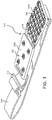
Fig. 1 is an isometric view of a midsole traction device in accordance with an aspect of an embodiment coupled to a strap; -
Fig. 2a is a bottom view of the midsole traction device; -
Fig. 2b is a bottom view of the midsole traction device coupled to the strap; and -
Fig. 3 is a top view of the midsole traction device coupled to the strap. - For convenience, like numerals in the description refer to like structures in the drawings. Referring to
Figs. 1 to 3 , a midsole traction device is illustrated generally bynumeral 100. Themidsole traction device 100 comprises afirst base portion 102, asecond base portion 104, and aflexible connector portion 106. Themidsole traction device 100 is coupled to astrap 108. Thestrap 104 includes aslide buckle 110. Theflexible connector portion 106 includes avisual indicator 130.Figs. 1 to 3 illustrate the configuration of themidsole traction device 100 for use with a left shoe. As will be appreciated by a person of ordinary skill in the art, the configuration of themidsole traction device 100 for use with a right shoe is a mirror image of themidsole traction device 100 for use with the left shoe - Each of the
first base portion 102 and thesecond base portion 104 includes aslot 112 at a distal end thereof. Each of theslots 112 is directed along the width of the correspondingfirst base portion 102 and the correspondingsecond base portion 104. Eachslot 112 includes arod 114 extending across a length thereof. Thestrap 108 is wrapped around the rod and secured in place, thereby coupling it to themidsole traction device 100. Thestrap 108 is configured to slide through theslide buckle 110 to adjust its length, as is known in the art. - Both the
first base portion 102 and thesecond base portion 104 are sized and shaped to fit mid-sole of the shoe, adjacent its heel. Inserts may be provided to increase the thickness of thefirst base portion 102 and thesecond base portion 104 if desired by the wearer, as is known in the art. - The
first base portion 102 comprises a firsttop side 102a and afirst bottom side 102b. Similarly, thesecond base portion 104 comprises a secondtop side 104a and asecond bottom side 104b. The relative terms "top" and "bottom" are defined with reference to themidsole traction device 100 in use. For example, the top side references a side that is configured to be positioned adjacent the shoe when in use. The bottom side references a side that is configured to be positioned adjacent the ground when in use. In an embodiment, the firsttop side 102a and the second top side are substantially flat. - The
first bottom side 102b comprises afirst traction aid 120. Thefirst traction aid 120 is configured to improve traction for the wearer on a first surface. Thesecond bottom side 104b comprises asecond traction aid 122. Thesecond traction aid 122 is different to thefirst traction aid 120. Thesecond traction aid 122 is configured to improve traction for the wearer on a second surface. - The
first traction aid 120 may comprise, for example, a plurality of cleats or spikes. Thecleats 120 are shaped and sized to pierce a surface such as snow or ice and improve the traction for the wearer. In the embodiment illustrated, thecleats 120 are arranged in an "X" configuration. As will be appreciated by a person skilled in the art, various shaped and sizedcleats 120 may be used depending on the surface for which themidsole traction device 100 is designed. Similarly, various numbers and configurations of thecleats 120 may also be used. - The
second traction aid 122 may comprise, for example, a plurality of grooves and channels in the surface of thesecond bottom side 102b. The grooves andchannels 122 are shaped and sized to allow water to flow there through, thereby improving traction for the wearer on a wet surface without the use of cleats. Such a traction aid may be useful, for example, on surfaces that may be damaged by the cleats or surface that are too strong for the cleats to pierce. As will be appreciated by a person skilled in the art, various shaped and sized grooves andchannels 122 may be used. Similarly, various patterns and configurations of the grooves andchannels 122 may also be used. - The
flexible connector portion 106 has afirst edge 106a extending between thefirst base portion 102 and thesecond base portion 104 andsecond edge 106b extending between thefirst base portion 102 and thesecond base portion 104. Thefirst edge 106a is shorter than thesecond edge 106b, thereby creating an offset angle α between thefirst base portion 102 and thesecond base portion 104. In an embodiment, an example of the offset angle α is approximately 15 degrees. In an embodiment, the longersecond edge 106b is to be positioned proximal to the heel. The shorterfirst edge 106a is to be positioned distal to heel. Further, in an embodiment, atop side 106c of theflexible connector portion 106 is corrugated. It is expected that the corrugation will improve the durability of theflexible connector portion 106 in cold weather conditions. - The
visual indicator 130 provides the wearer with an indication of the proper positioning of themidsole traction device 100. In an example, thevisual indicator 130 includes anarrow 130a and aletter 130b. Theletter 130b identifies whether the midsole traction device is for a left (L) shoe or for a right (R) shoe. Thearrow 130a is pointed towards the shorterfirst edge 106a of theflexible connector 106. Thus, for example, if the wearer places themidsole traction device 100 on a left or right shoe as indicated by theletter 130b with thearrow 130a directed towards the toe of the shoe, then themidsole traction device 100 will be properly aligned with the shoe. - Although the
midsole traction device 100 is described above with respect to a particular embodiment, other embodiments will be apparent to those skilled in the art in view of this disclosure. For example, thestrap 108 can be coupled to themidsole traction device 100 without the use of therod 114. Instead, thestrap 108 can pass through theslot 112 and wrap around an edge of the base adjacent the slot. As another example, a connector portion can be molded to the outer opposing edges of themidsole traction device 100, and thestrap 108 could be coupled to the connector portion. Yet further, theslide buckle 110 is only one example of a buckle type that could be used. Other types of buckles include conventional buckles, side release buckles, ratchet buckle, and the like. Additionally, rather than a buckle, other types of connectors, such as Velcro® can be used. - As described above, the
first traction aid 120 and thesecond traction aid 122 are provided for different surfaces. However, in an alternative embodiment, thefirst traction aid 120 and thesecond traction aid 122 may provide different levels of traction for the same surface. That is, for example, thesecond traction aid 122 may also be configured with cleats, rather than the grooves and channels illustrated inFigs. 1 to 3 . However, the cleats forming thesecond traction aid 122 could be shorter or longer than the cleats forming thefirst traction aid 120, thereby providing the wearer with different levels of traction for ice and snow. The cleats in thesecond traction aid 122 could also be configured in a different configuration and/or with a different number of cleats, further distinguishing its capability from the capability of thefirst traction aid 120. - Yet further, although the
flexible connector portion 106 is corrugated on itstop portion 106c, it may be corrugated on its bottom portion, on both top and bottom portions, or not at all. Although, these embodiments may not provide the same durability, they may provide sufficient durability for some implementations of themidsole traction device 100. - These and other variations upon the embodiments are intended to be covered by the present disclosure, which is limited only by the appended claims.
Claims (11)
- A midsole traction device comprising:a first base portion comprising a first traction aid on a first side of the midsole traction device;a second base portion comprising a second traction aid of the first side of the midsole traction device, the second traction aid is different to the first traction aid; anda flexible connector portion connecting the first base portion to the second base portion.
- The midsole traction device of claim 1, wherein the flexible connector portion comprises:a first edge extending between the first base portion and the second base portion; anda second edge extending between the first base portion and the second base portion;wherein the first edge is shorter than the second edge, thereby creating an offset angle α between the first base portion and the second base portion.
- The midsole traction device of claim 2, wherein the offset angle is approximately 15 degrees.
- The midsole traction device of any one of claims 1 to 3, wherein the flexible connector portion is corrugated on one side.
- The midsole traction device of claim 4, wherein the flexible connector portion is corrugated on a second side of the midsole traction device, the second side opposite the first side.
- The midsole traction device of any one of claims 1 to 5, wherein the first traction aid and second traction aid are configured to provide traction on different surfaces.
- The midsole traction device of any one of claims 1 to 5, wherein the first traction aid and second traction aid are configured to provide different traction on the same surface.
- The midsole traction device of any one of claims 1 to 7, wherein the first traction aid comprises a plurality of cleats.
- The midsole traction device of claim 8, wherein the second traction aid comprises a plurality of cleats, the plurality of cleats in the second traction aid differing from the plurality of cleats in first traction aid by at least one of size, number of cleats, and configuration.
- The midsole traction device of any one of claims 1 to 8, wherein the second traction aid comprises a plurality of grooves and channels in a predefined configuration.
- The midsole traction device of any one of claims 1 to 10 further comprising a strap for securing the midsole traction device to a wearer's footwear.
Applications Claiming Priority (1)
| Application Number | Priority Date | Filing Date | Title |
|---|---|---|---|
| US202063046124P | 2020-06-30 | 2020-06-30 |
Publications (1)
| Publication Number | Publication Date |
|---|---|
| EP3932240A1 true EP3932240A1 (en) | 2022-01-05 |
Family
ID=76730319
Family Applications (1)
| Application Number | Title | Priority Date | Filing Date |
|---|---|---|---|
| EP21182684.7A Withdrawn EP3932240A1 (en) | 2020-06-30 | 2021-06-30 | Midsole traction device |
Country Status (3)
| Country | Link |
|---|---|
| US (1) | US11717057B2 (en) |
| EP (1) | EP3932240A1 (en) |
| CA (1) | CA3123541C (en) |
Families Citing this family (7)
| Publication number | Priority date | Publication date | Assignee | Title |
|---|---|---|---|---|
| USD807005S1 (en) * | 2016-07-06 | 2018-01-09 | Geroline Inc. | Mid-sole cleat |
| USD1000081S1 (en) * | 2020-02-13 | 2023-10-03 | Geroline Inc. | Mid-sole cleat |
| CA196629S (en) * | 2020-06-30 | 2022-05-05 | Geroline Inc | Mid-sole cleat |
| CA197134S (en) | 2020-07-27 | 2022-05-12 | Dentec Safety Specialists Inc | Heel traction device |
| CA197133S (en) * | 2020-07-27 | 2022-05-12 | Dentec Safety Specialists Inc | Mid-sole traction device |
| CA3088637A1 (en) | 2020-07-31 | 2022-01-31 | Dentec Safety Specialists Inc. | Heel traction device |
| CA205138S (en) | 2021-07-23 | 2023-03-01 | Dentec Safety Specialists Inc | Heel traction device |
Citations (10)
| Publication number | Priority date | Publication date | Assignee | Title |
|---|---|---|---|---|
| US2166958A (en) | 1937-11-02 | 1939-07-25 | Frans O Lawson | Antislipping device |
| US2208200A (en) | 1938-02-11 | 1940-07-16 | George E Sloan | Ice walker |
| US2366649A (en) | 1943-11-08 | 1945-01-02 | Louis A Priess | Ice gripper |
| US3520075A (en) * | 1969-02-10 | 1970-07-14 | Josiah W Mullikin | Detachable golf spike attachment |
| US4702021A (en) | 1986-10-07 | 1987-10-27 | Cameron Emmet H | Shoe traction apparatus |
| US5485687A (en) | 1994-03-28 | 1996-01-23 | Rohde; Gilbert | Anti-slip shoe attachment device |
| US6154982A (en) * | 1999-08-20 | 2000-12-05 | Michael Bell | Readily mountable traction enhancing attachment for footwear |
| US20130312282A1 (en) * | 2012-05-22 | 2013-11-28 | Salomon S.A.S. | Footwear crampon |
| KR20140135529A (en) * | 2013-05-16 | 2014-11-26 | 한국과학기술원 | Anti-slip pad usable in various conditions |
| US20150007460A1 (en) * | 2013-07-04 | 2015-01-08 | Salomon Sas | Footwear crampon |
Family Cites Families (32)
| Publication number | Priority date | Publication date | Assignee | Title |
|---|---|---|---|---|
| US36866A (en) | 1862-11-04 | Improved ice-clog | ||
| US156094A (en) | 1874-10-20 | Improvement in ice-creepers | ||
| US905510A (en) | 1908-04-20 | 1908-12-01 | Samuel Frautschi Jr | Antislipping device for shoes. |
| US1018708A (en) * | 1910-12-14 | 1912-02-27 | John R Hetrick | Shoe-protector. |
| US1032600A (en) | 1912-01-27 | 1912-07-16 | Edward A Grout | Ice-creeper. |
| US1275917A (en) | 1917-12-11 | 1918-08-13 | Fred Herman | Ice-creeper. |
| US2006802A (en) | 1934-01-30 | 1935-07-02 | Clarence J Goodman | Antislip device |
| US2045066A (en) | 1935-12-06 | 1936-06-23 | Charles L Bower | Log gripping calk plate |
| US2179178A (en) | 1939-03-03 | 1939-11-07 | Farlin Helmer | Shoe attachment |
| US2296660A (en) | 1941-04-22 | 1942-09-22 | Karl F Bauerschmidt | Ice creeper |
| US2313316A (en) | 1942-03-04 | 1943-03-09 | Emil F Block | Antislipping device |
| US2401891A (en) | 1944-11-14 | 1946-06-11 | Samuel A Smith | Ice creeper |
| US2431748A (en) | 1946-03-29 | 1947-12-02 | Gershak Tony | Ice creeper |
| US2438193A (en) | 1946-11-08 | 1948-03-23 | Smith Wayne | Shoe antiskid device |
| US2636175A (en) | 1950-08-14 | 1953-04-28 | Jr George R Hoffman | Body supported perspiration absorbing device |
| US2658289A (en) | 1951-06-21 | 1953-11-10 | Herbert S Schrieber | Footwear calk assembly |
| US3691659A (en) | 1971-02-01 | 1972-09-19 | Kazunari Nakajima | Non-slip safety sole clampons |
| US3838528A (en) | 1973-02-01 | 1974-10-01 | G Johnson | Anti-skid device for boots and shoes |
| US4005533A (en) | 1975-11-07 | 1977-02-01 | Anderson Gordon K | Instep crampons |
| USD262157S (en) | 1980-04-07 | 1981-12-08 | Custom Safety Products | Safety cleat or similar article |
| US4525939A (en) * | 1983-10-24 | 1985-07-02 | Mcneil Reginald K | Boot safety attachment |
| USD336559S (en) | 1991-03-25 | 1993-06-22 | Bruce Carmichael | Device to increase foot traction |
| US5659978A (en) * | 1994-08-26 | 1997-08-26 | Michael Bell | Footwear having a sole with a toe strapping assembly |
| US6434859B1 (en) | 1999-09-30 | 2002-08-20 | Joo Tae Kim | Insole for shoes designed to increase a therapeutic effect based on reflex zone therapy |
| US20050241179A1 (en) * | 2004-04-29 | 2005-11-03 | Eddie Chen | Shoe with breathable shell |
| US8661708B2 (en) * | 2006-11-06 | 2014-03-04 | Wookyung Tech Co., Ltd. | Crampon for golf shoes and climbing irons |
| US8371045B2 (en) | 2009-10-13 | 2013-02-12 | Georges-André Tambay | Hiking boot attachment for descending slopes |
| US20130312294A1 (en) * | 2012-05-24 | 2013-11-28 | Poesen Electronic Co., Ltd. | Strap-on shoe anti-slip device |
| US20170251765A1 (en) | 2016-03-07 | 2017-09-07 | Bryce Everett Romeril | High Traction Crampon |
| USD790172S1 (en) | 2016-03-11 | 2017-06-27 | Nike, Inc. | Shoe sole |
| USD807005S1 (en) | 2016-07-06 | 2018-01-09 | Geroline Inc. | Mid-sole cleat |
| USD879443S1 (en) | 2018-07-19 | 2020-03-31 | Sure Foot Corporation | Mid-sole cleat |
-
2021
- 2021-06-29 CA CA3123541A patent/CA3123541C/en active Active
- 2021-06-30 US US17/363,977 patent/US11717057B2/en active Active
- 2021-06-30 EP EP21182684.7A patent/EP3932240A1/en not_active Withdrawn
Patent Citations (10)
| Publication number | Priority date | Publication date | Assignee | Title |
|---|---|---|---|---|
| US2166958A (en) | 1937-11-02 | 1939-07-25 | Frans O Lawson | Antislipping device |
| US2208200A (en) | 1938-02-11 | 1940-07-16 | George E Sloan | Ice walker |
| US2366649A (en) | 1943-11-08 | 1945-01-02 | Louis A Priess | Ice gripper |
| US3520075A (en) * | 1969-02-10 | 1970-07-14 | Josiah W Mullikin | Detachable golf spike attachment |
| US4702021A (en) | 1986-10-07 | 1987-10-27 | Cameron Emmet H | Shoe traction apparatus |
| US5485687A (en) | 1994-03-28 | 1996-01-23 | Rohde; Gilbert | Anti-slip shoe attachment device |
| US6154982A (en) * | 1999-08-20 | 2000-12-05 | Michael Bell | Readily mountable traction enhancing attachment for footwear |
| US20130312282A1 (en) * | 2012-05-22 | 2013-11-28 | Salomon S.A.S. | Footwear crampon |
| KR20140135529A (en) * | 2013-05-16 | 2014-11-26 | 한국과학기술원 | Anti-slip pad usable in various conditions |
| US20150007460A1 (en) * | 2013-07-04 | 2015-01-08 | Salomon Sas | Footwear crampon |
Also Published As
| Publication number | Publication date |
|---|---|
| CA3123541C (en) | 2023-10-31 |
| US20210401125A1 (en) | 2021-12-30 |
| CA3123541A1 (en) | 2021-12-30 |
| US11717057B2 (en) | 2023-08-08 |
Similar Documents
| Publication | Publication Date | Title |
|---|---|---|
| EP3932240A1 (en) | Midsole traction device | |
| US6813847B2 (en) | Boot with replaceable sole plate | |
| US5966840A (en) | Traction altering footwear attachment device with resilient mounting ring and fiber ground engagement surface | |
| US4258483A (en) | Protective device for spiked athletic shoes | |
| US5638614A (en) | Shoe protector and floor covering aid | |
| US5943792A (en) | Footwear traction device | |
| US20100175280A1 (en) | Footwear assemblies with removable enhanced traction devices and associated methods of use and manufacture | |
| US8112910B2 (en) | Shoe wrap and system | |
| CA2366089A1 (en) | Sole for footwear or footwear attachment having multilevel cleats for indicating wear and providing enhanced traction and flexibility | |
| US8539695B1 (en) | Footwear device | |
| EP3123883A1 (en) | A sole of a shoe | |
| US11751638B2 (en) | Heel traction device | |
| CA3088629A1 (en) | Mid-sole traction device | |
| US6981294B2 (en) | Carpet slide for recreational use | |
| US2932096A (en) | Anti-slip device | |
| EP3827691A1 (en) | Footwear traction device and method of using the same | |
| US2296660A (en) | Ice creeper | |
| KR20140108767A (en) | Sliding prevention out-sole | |
| KR20160028243A (en) | Non-Slip Apparatus On Icy Road | |
| WO2000004802A1 (en) | Improved slip resistant shoe sole | |
| KR200238313Y1 (en) | Crampons | |
| JP3225702U (en) | Anti-slip equipment for shoes | |
| EP2430936A1 (en) | Anti-slip device | |
| KR200267906Y1 (en) | The attaching and detaching nonskid apparatus for a shoes | |
| JP3010859U (en) | Non-slip shoe pad |
Legal Events
| Date | Code | Title | Description |
|---|---|---|---|
| PUAI | Public reference made under article 153(3) epc to a published international application that has entered the european phase |
Free format text: ORIGINAL CODE: 0009012 |
|
| STAA | Information on the status of an ep patent application or granted ep patent |
Free format text: STATUS: THE APPLICATION HAS BEEN PUBLISHED |
|
| AK | Designated contracting states |
Kind code of ref document: A1 Designated state(s): AL AT BE BG CH CY CZ DE DK EE ES FI FR GB GR HR HU IE IS IT LI LT LU LV MC MK MT NL NO PL PT RO RS SE SI SK SM TR |
|
| B565 | Issuance of search results under rule 164(2) epc |
Effective date: 20211115 |
|
| STAA | Information on the status of an ep patent application or granted ep patent |
Free format text: STATUS: THE APPLICATION IS DEEMED TO BE WITHDRAWN |
|
| 18D | Application deemed to be withdrawn |
Effective date: 20220706 |