EP3932180A1 - Twine tension sensor arrangement - Google Patents
Twine tension sensor arrangement Download PDFInfo
- Publication number
- EP3932180A1 EP3932180A1 EP21161862.4A EP21161862A EP3932180A1 EP 3932180 A1 EP3932180 A1 EP 3932180A1 EP 21161862 A EP21161862 A EP 21161862A EP 3932180 A1 EP3932180 A1 EP 3932180A1
- Authority
- EP
- European Patent Office
- Prior art keywords
- displacement
- control unit
- signals
- twine
- signal
- Prior art date
- Legal status (The legal status is an assumption and is not a legal conclusion. Google has not performed a legal analysis and makes no representation as to the accuracy of the status listed.)
- Granted
Links
Images

Classifications
-
- A—HUMAN NECESSITIES
- A01—AGRICULTURE; FORESTRY; ANIMAL HUSBANDRY; HUNTING; TRAPPING; FISHING
- A01F—PROCESSING OF HARVESTED PRODUCE; HAY OR STRAW PRESSES; DEVICES FOR STORING AGRICULTURAL OR HORTICULTURAL PRODUCE
- A01F15/00—Baling presses for straw, hay or the like
- A01F15/08—Details
- A01F15/12—Feeding devices for the ties
-
- A—HUMAN NECESSITIES
- A01—AGRICULTURE; FORESTRY; ANIMAL HUSBANDRY; HUNTING; TRAPPING; FISHING
- A01F—PROCESSING OF HARVESTED PRODUCE; HAY OR STRAW PRESSES; DEVICES FOR STORING AGRICULTURAL OR HORTICULTURAL PRODUCE
- A01F15/00—Baling presses for straw, hay or the like
- A01F15/08—Details
- A01F15/0841—Drives for balers
- A01F15/0858—Drives for balers for the tying devices or needles
-
- A—HUMAN NECESSITIES
- A01—AGRICULTURE; FORESTRY; ANIMAL HUSBANDRY; HUNTING; TRAPPING; FISHING
- A01F—PROCESSING OF HARVESTED PRODUCE; HAY OR STRAW PRESSES; DEVICES FOR STORING AGRICULTURAL OR HORTICULTURAL PRODUCE
- A01F15/00—Baling presses for straw, hay or the like
- A01F15/08—Details
- A01F15/14—Tying devices specially adapted for baling presses
- A01F15/145—Twine knotters
Definitions
- the present invention relates to a mechanism for use in tying loops of twine about rectangular bales, and to a baler incorporating such a mechanism.
- Rectangular bales are able to maintain their shape by means of a series of parallel extending twine loops, provided lengthwise around the bales.
- Current large square balers are equipped with a plurality of pivotally mounted, upwardly biased twine tensioner arms each associated with a plurality of knotter assemblies to maintain proper tension on the twine to ensure each knotter assembly performs properly.
- the twine is drawn from suitable twine boxes. If the twine tensioner arm fails to maintain proper tension on the twine, the twine can be pulled out of the knotter assembly and a mistie occurs.
- a number of factors affect the tension on the twine. Sometimes twine gets tangled in the twine box which makes it difficult or impossible for the baler to make knots. In extreme situations baler components may become damaged as a result. This is clearly a problem.
- a twine tensioner arrangement for a baler comprises a pair of rollers, each of the rollers being rotatable about a shaft and having circumferential lobes engaging each other in a meshing arrangement, at least one of the shafts being mounted on a displaceable armature, displacement measurement apparatus to measure the displacement of the displaceable armature and a signalling apparatus to generate a signal if the displacement of the displaceable armature exceeds a predetermined value.
- the signalling apparatus Preferably the signalling apparatus generates the signal if the displacement of the armature exceeds a predetermined value for a predetermined period of time.
- the signalling apparatus does not generate a signal where a brief increase in twine tension may be present, for example in the event of a momentary spike in twine tension required to work out a "natural memory" near tangle condition which works itself out as a strand of twine flows through the twine tensioner arrangement or generate a signal, for example, where passage of a knot joining two balls of twine will cause displacement of the displaceable armature without there being an increase in twine tension.
- the signalling apparatus further comprises a control unit in communication with the displacement measurement apparatus and a user terminal, the control unit being adapted to receive signals from the displacement measurement apparatus, determine whether the signals from the displacement measurement apparatus represent displacement of the displaceable armature in excess of a predetermined value and if the signals from the displacement measurement apparatus represent displacement of the displaceable armature in excess of a predetermined value to generate a signal to the user terminal.
- a control unit in communication with the displacement measurement apparatus and a user terminal, the control unit being adapted to receive signals from the displacement measurement apparatus, determine whether the signals from the displacement measurement apparatus represent displacement of the displaceable armature in excess of a predetermined value and if the signals from the displacement measurement apparatus represent displacement of the displaceable armature in excess of a predetermined value to generate a signal to the user terminal.
- the control unit additionally generates a signal causing operation of the baler to cease.
- a baler in a combination comprising an agricultural vehicle and a baler towed by the agricultural vehicle, the baler comprising a plurality of knotters, each knotter having a twine tensioner arrangement comprising a pair of rollers, each roller being rotatable about a shaft and having circumferential lobes, at least one of the shafts being displaceable, and displacement measurement apparatus to generate a displacement signal representative of a displacement of the at least one shaft
- the combination further comprising a user terminal associated with the agricultural vehicle, a control unit and a memory in communication with the control unit, the control unit being configured to receive a plurality of signals including the displacement signals representative of the displacement of the at least one shaft in each twine tensioner arrangement and to compare the displacement signals against a predetermined set of values stored in the memory to determine whether an error condition exists and in the event of an error condition the control unit being configured to generate and send a signal to the user terminal to a cause an indication of the error condition to be generated by the user terminal.
- each of the displaceable shafts is mounted on a displaceable armature.
- the control unit can also generate a signal causing operation of the baler to cease.
- the indication of the error condition to be generated by the user terminal is a visual and/or an audible indication.
- a computer implemented method comprises the steps of a control unit receiving a plurality of signals, the signals representing a displacement of at least one shaft in each twine tensioner arrangement according to the first aspect of the invention, the control unit being configured to receive a plurality of signals including the displacement signals representative of the displacement of the at least one shaft in each twine tensioner arrangement and to compare the displacement signals against a predetermined set of values stored in the memory to determine whether an error condition exists and in the event of an error condition the control unit being configured to generate and send a signal to a user terminal to a cause an indication of the error condition to be generated by the user terminal.
- the control unit can also generate a signal causing operation of the baler to cease.
- a computer readable program comprises instructions that cause one or more processors to implement the method of the third aspect of the invention.
- a baler is provided with a plurality of knotter assemblies.
- a strand of twine is drawn from a supply roll provided in a twine box located to the side of the baler through a plurality of twine guides provided in side plates of the baler and through a final twine guide associated with a twine tensioner assembly before entering the twine tensioner assembly.
- Each knotter assembly is provided with its own associated twine tensioner assembly. The twine then passes from the twine tensioner assembly to a tensioner arm of the associated knotter assembly.
- each twine tensioner assembly 2 includes a twine tensioner or gripper including upper and lower rollers 4 and 6, respectively.
- Each of the rollers 4,6 is adapted to rotate about a central shaft 8,10 and is provided with circumferential ridges, ribs or lobes 14,16.
- the central shaft 8 of the upper roller 4 is offset vertically and horizontally with respect to the central shaft 10 of the lower roller 6. It will be understood that other arrangements of the upper and lower rollers are possible.
- the ribs or lobes 16 of the lower roller 6 are in a meshed arrangement with ribs or lobes 14 of the upper roller 4.
- the rollers 4 and 6 are biased together so as to maintain a tension in a length of twine being pulled through a nip of the meshed rollers 4,6.
- rollers 4 and 6 may be biased together in any suitable manner.
- a spring assembly 20 is used to bias the rollers 4, 6 together.
- the central shaft 8 of the upper roller 4 may be supported on a spring biased element, such as a spring biased armature.
- This displacement may be measured, for example by suitable measuring device capable of generating a measurement signal, for example a potentiometer 24 provided on a frame 26 of the twine tensioner assembly 2.
- the measurement signal is communicated to an electronic control unit 40.
- the electronic control unit 40 is in communication with a user terminal 42.
- the user terminal 40 is conveniently located in the driver's cab of an agricultural vehicle towing the baler.
- a suitable data communication network 44 such as one compliant with the ISOBUS standard (a network in conformance to ISO 11783).
- the control unit 40 may conveniently comprise a single processor located on the agricultural vehicle towing the baler or its functions may be split between a processor located on the agricultural vehicle and one or more additional processors located on the baler, the additional processor(s) being in electronic communication with the first processor.
- the control unit 40 is also able to access a suitable memory 46.
- the memory 46 may take any suitable form and is in electronic communication with the control unit 40.
- the memory 46 is adapted to store, in any suitable manner such as a database or look up table, reference values relating to the measurement signal.
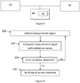
- the control unit receives measurement signals from the measuring device, in the illustrated embodiment, the potentiometer (step 100, Figure 4 ).
- the measurement signals are compared to the reference values in the memory (step 102).
- the control unit determines if an error condition is present (step 104).
- Such an error condition may correspond to a measurement signal in excess of a predetermined value or a series of measurement signals exceeding a predetermined value over a predetermined time interval.
- a signal is sent by the control unit 40 to the user terminal to alert an operator of the baler of the existence of an error condition (step 106). In the absence of an error condition being determined no signal is sent.
- control unit 40 also generates a signal to cause the operation of the baler to cease, preferably if the measurement signal is significantly greater than that required for the initial notification of an error condition.
- the user terminal 42 may indicate the error condition to the operator in any suitable manner, for example by way of a visual signal and/or an audible signal. Since each twine tensioner arrangement is monitored, the signal from the control unit 40 to the user terminal 42 can indicate which twine tensioner assembly 2 has caused the signal to be generated, thereby enabling the operator quickly to identify the location of the problem and so address the cause of the problem.
Landscapes
- Life Sciences & Earth Sciences (AREA)
- Environmental Sciences (AREA)
- Force Measurement Appropriate To Specific Purposes (AREA)
- Protection Of Plants (AREA)
- Agricultural Machines (AREA)
Abstract
Description
- The present invention relates to a mechanism for use in tying loops of twine about rectangular bales, and to a baler incorporating such a mechanism.
- Rectangular bales are able to maintain their shape by means of a series of parallel extending twine loops, provided lengthwise around the bales. Current large square balers are equipped with a plurality of pivotally mounted, upwardly biased twine tensioner arms each associated with a plurality of knotter assemblies to maintain proper tension on the twine to ensure each knotter assembly performs properly. The twine is drawn from suitable twine boxes. If the twine tensioner arm fails to maintain proper tension on the twine, the twine can be pulled out of the knotter assembly and a mistie occurs. A number of factors affect the tension on the twine. Sometimes twine gets tangled in the twine box which makes it difficult or impossible for the baler to make knots. In extreme situations baler components may become damaged as a result. This is clearly a problem.
- It is further a problem that an operator of the baler will not know there is a problem until the knot has been missed or damage to baler components has occurred.
- It is an advantage of the present invention that it seeks to address these problems.
- According to a first aspect of the present invention, a twine tensioner arrangement for a baler comprises a pair of rollers, each of the rollers being rotatable about a shaft and having circumferential lobes engaging each other in a meshing arrangement, at least one of the shafts being mounted on a displaceable armature, displacement measurement apparatus to measure the displacement of the displaceable armature and a signalling apparatus to generate a signal if the displacement of the displaceable armature exceeds a predetermined value.
- This has as an advantage that a tension in a strand of twine entering the twine tensioner arrangement can be monitored and action taken to avoid a mistie or damage to the baler components.
- Preferably the signalling apparatus generates the signal if the displacement of the armature exceeds a predetermined value for a predetermined period of time.
- This has as an advantage that the signalling apparatus does not generate a signal where a brief increase in twine tension may be present, for example in the event of a momentary spike in twine tension required to work out a "natural memory" near tangle condition which works itself out as a strand of twine flows through the twine tensioner arrangement or generate a signal, for example, where passage of a knot joining two balls of twine will cause displacement of the displaceable armature without there being an increase in twine tension.
- Preferably the signalling apparatus further comprises a control unit in communication with the displacement measurement apparatus and a user terminal, the control unit being adapted to receive signals from the displacement measurement apparatus, determine whether the signals from the displacement measurement apparatus represent displacement of the displaceable armature in excess of a predetermined value and if the signals from the displacement measurement apparatus represent displacement of the displaceable armature in excess of a predetermined value to generate a signal to the user terminal.
- Alternatively or additionally, if the signals from the displacement measurement apparatus represent displacement of the displaceable armature in excess of a predetermined value the control unit additionally generates a signal causing operation of the baler to cease.
- According to a second aspect of the invention, in a combination comprising an agricultural vehicle and a baler towed by the agricultural vehicle, the baler comprising a plurality of knotters, each knotter having a twine tensioner arrangement comprising a pair of rollers, each roller being rotatable about a shaft and having circumferential lobes, at least one of the shafts being displaceable, and displacement measurement apparatus to generate a displacement signal representative of a displacement of the at least one shaft, the combination further comprising a user terminal associated with the agricultural vehicle, a control unit and a memory in communication with the control unit, the control unit being configured to receive a plurality of signals including the displacement signals representative of the displacement of the at least one shaft in each twine tensioner arrangement and to compare the displacement signals against a predetermined set of values stored in the memory to determine whether an error condition exists and in the event of an error condition the control unit being configured to generate and send a signal to the user terminal to a cause an indication of the error condition to be generated by the user terminal.
- Preferably, each of the displaceable shafts is mounted on a displaceable armature.
- Alternatively or additionally, if the signals from the displacement measurement apparatus represent displacement of at least one displaceable shaft in excess of a predetermined value the control unit can also generate a signal causing operation of the baler to cease.
- Preferably the indication of the error condition to be generated by the user terminal is a visual and/or an audible indication.
- According to a third aspect of the invention, a computer implemented method comprises the steps of a control unit receiving a plurality of signals, the signals representing a displacement of at least one shaft in each twine tensioner arrangement according to the first aspect of the invention, the control unit being configured to receive a plurality of signals including the displacement signals representative of the displacement of the at least one shaft in each twine tensioner arrangement and to compare the displacement signals against a predetermined set of values stored in the memory to determine whether an error condition exists and in the event of an error condition the control unit being configured to generate and send a signal to a user terminal to a cause an indication of the error condition to be generated by the user terminal.
- Preferably, if the signals from the displacement measurement apparatus represent displacement of the at least one shaft in excess of a predetermined value the control unit can also generate a signal causing operation of the baler to cease.
- According to a fourth aspect of the present invention, a computer readable program comprises instructions that cause one or more processors to implement the method of the third aspect of the invention.
- The invention will now be described, by way of example only, with reference to the accompanying drawings, in which:
-
Figure 1 shows a twine tensioner assembly in accordance with the present invention in which the elements of the assembly are in a first working configuration; -
Figure 2 shows the twine tensioner assembly ofFigure 1 in which the elements of the assembly are in a second erroneous configuration; -
Figure 3 shows a schematic view of elements of a baler for use in the present invention; and -
Figure 4 shows a flow diagram illustrating an example control method for the present invention. - The invention will now be described in the following detailed description with reference to the drawings, wherein preferred embodiments are described in detail to enable practice of the invention. Although the invention is described with reference to these specific preferred embodiments, it will be understood that the invention is not limited to these preferred embodiments. But to the contrary, the invention includes numerous alternatives, modifications and equivalents as will become apparent from consideration of the following detailed description.
- A baler is provided with a plurality of knotter assemblies. In use, in order to provide twine to each knotter assembly, a strand of twine is drawn from a supply roll provided in a twine box located to the side of the baler through a plurality of twine guides provided in side plates of the baler and through a final twine guide associated with a twine tensioner assembly before entering the twine tensioner assembly. Each knotter assembly is provided with its own associated twine tensioner assembly. The twine then passes from the twine tensioner assembly to a tensioner arm of the associated knotter assembly.
- Referring to
Figures 1 and 2 , each twine tensioner assembly 2 includes a twine tensioner or gripper including upper andlower rollers rollers central shaft lobes central shaft 8 of theupper roller 4 is offset vertically and horizontally with respect to thecentral shaft 10 of thelower roller 6. It will be understood that other arrangements of the upper and lower rollers are possible. - In
Figure 1 , the ribs orlobes 16 of thelower roller 6 are in a meshed arrangement with ribs orlobes 14 of theupper roller 4. Therollers meshed rollers - The
rollers - Conveniently, a
spring assembly 20 is used to bias therollers central shaft 8 of theupper roller 4 may be supported on a spring biased element, such as a spring biased armature. - When a strand of
twine 30 is flowing freely into the twine tensioner assembly 2, the tension in the strand oftwine 30 is low and the strand oftwine 30 is easily deformed between thelobes rollers 4,6 (as inFigure 1 ). - However, if (as shown in
Figure 2 ) the strand oftwine 30 becomes snagged, knotted or otherwise fails to flow freely into the twine tensioner assembly 2, the tension in the strand oftwine 30 increases such that the strand oftwine 30 is deformed significantly less by theroller lobes upper roller 4 to be displaced against the action of thespring assembly 20, for example by the armature being displaced around a pivot point (not shown). - This displacement may be measured, for example by suitable measuring device capable of generating a measurement signal, for example a
potentiometer 24 provided on aframe 26 of the twine tensioner assembly 2. - The measurement signal is communicated to an
electronic control unit 40. Theelectronic control unit 40 is in communication with auser terminal 42. Theuser terminal 40 is conveniently located in the driver's cab of an agricultural vehicle towing the baler. - Conveniently communication occurs by way of a suitable data communication network 44 such as one compliant with the ISOBUS standard (a network in conformance to ISO 11783).
- The
control unit 40 may conveniently comprise a single processor located on the agricultural vehicle towing the baler or its functions may be split between a processor located on the agricultural vehicle and one or more additional processors located on the baler, the additional processor(s) being in electronic communication with the first processor. - The
control unit 40 is also able to access asuitable memory 46. Thememory 46 may take any suitable form and is in electronic communication with thecontrol unit 40. Thememory 46 is adapted to store, in any suitable manner such as a database or look up table, reference values relating to the measurement signal. - In operation, the control unit receives measurement signals from the measuring device, in the illustrated embodiment, the potentiometer (
step 100,Figure 4 ). The measurement signals are compared to the reference values in the memory (step 102). The control unit determines if an error condition is present (step 104). Such an error condition may correspond to a measurement signal in excess of a predetermined value or a series of measurement signals exceeding a predetermined value over a predetermined time interval. In the event of an error condition being determined, a signal is sent by thecontrol unit 40 to the user terminal to alert an operator of the baler of the existence of an error condition (step 106). In the absence of an error condition being determined no signal is sent. - In a preferred embodiment, the
control unit 40 also generates a signal to cause the operation of the baler to cease, preferably if the measurement signal is significantly greater than that required for the initial notification of an error condition. - The
user terminal 42 may indicate the error condition to the operator in any suitable manner, for example by way of a visual signal and/or an audible signal. Since each twine tensioner arrangement is monitored, the signal from thecontrol unit 40 to theuser terminal 42 can indicate which twine tensioner assembly 2 has caused the signal to be generated, thereby enabling the operator quickly to identify the location of the problem and so address the cause of the problem. - From reading the present disclosure, other modifications will be apparent to persons skilled in the art. Such modifications may involve other features which are already known in the field of square balers and component parts therefore and which may be used instead of or in addition to features already described herein.
Claims (11)
- A twine tensioner arrangement for a baler comprises a pair of rollers, each of the rollers being rotatable about a shaft and having circumferential lobes, at least one of the shafts being mounted on a displaceable armature, displacement measurement apparatus to measure the displacement of the displaceable armature and a signalling apparatus to generate a signal if the displacement of the displaceable armature exceeds a predetermined value.
- A twine tensioner arrangement according to claim 1, in which the signalling apparatus generates the signal if the displacement of the armature exceeds a predetermined value for a predetermined period of time.
- A twine tensioner arrangement according to claim 1, in which the signalling apparatus further comprises a control unit in communication with the displacement measurement apparatus and a user terminal, the control unit being adapted to receive signals from the displacement measurement apparatus, determine whether the signals from the displacement measurement apparatus represent displacement of the displaceable armature in excess of a predetermined value and if the signals from the displacement measurement apparatus represent displacement of the displaceable armature in excess of a predetermined value to generate a signal to the user terminal.
- A twine tensioner arrangement according to claim 1, in which if the signals from the displacement measurement apparatus represent displacement of the displaceable armature in excess of a predetermined value the control unit additionally generates a signal causing operation of the baler to cease.
- A combination comprising an agricultural vehicle and a baler towed by the agricultural vehicle, the baler comprising a plurality of knotters, each knotter having a twine tensioner arrangement comprising a pair of rollers, each roller being rotatable about a shaft and having circumferential lobes, at least one of the shafts being displaceable, and displacement measurement apparatus to generate a displacement signal representative of a displacement of the at least one shaft, the combination further comprising a user terminal associated with the agricultural vehicle, a control unit and a memory in communication with the control unit, the control unit being configured to receive a plurality of signals including the displacement signals representative of the displacement of the at least one shaft in each twine tensioner arrangement and to compare the displacement signals against a predetermined set of values stored in the memory to determine whether an error condition exists and in the event of an error condition the control unit being configured to generate and send a signal to the user terminal to a cause an indication of the error condition to be generated by the user terminal.
- A combination according to claim 5, in which the or each of the displaceable shafts is mounted on a displaceable armature.
- A combination according to claim 5, in which when the signals from the displacement measurement apparatus represent displacement of the at least one shaft in excess of the predetermined value the control unit also generates a signal causing operation of the baler to cease.
- A combination according to claim 5, in which the indication of the error condition to be generated by the user terminal is a visual and/or an audible indication.
- A computer implemented method comprises the steps of a control unit receiving a plurality of signals, the signals representing a displacement of at least one shaft in each twine tensioner arrangement according to the first aspect of the invention, the control unit being configured to receive a plurality of signals including the displacement signals representative of the displacement of the at least one shaft in each twine tensioner arrangement and to compare the displacement signals against a predetermined set of values stored in the memory to determine whether an error condition exists and in the event of an error condition the control unit being configured to generate and send a signal to a user terminal to a cause an indication of the error condition to be generated by the user terminal.
- A computer implemented method according to claim 10, in which when the signals from the displacement measurement apparatus represent displacement of the at least one shaft in excess of a predetermined value the control unit also generates a signal causing operation of the baler to cease.
- A computer readable program comprises instructions that cause one or more processors to implement the method of claim 9.
Applications Claiming Priority (1)
| Application Number | Priority Date | Filing Date | Title |
|---|---|---|---|
| US202063046802P | 2020-07-01 | 2020-07-01 |
Publications (2)
| Publication Number | Publication Date |
|---|---|
| EP3932180A1 true EP3932180A1 (en) | 2022-01-05 |
| EP3932180B1 EP3932180B1 (en) | 2024-09-18 |
Family
ID=74870766
Family Applications (1)
| Application Number | Title | Priority Date | Filing Date |
|---|---|---|---|
| EP21161862.4A Active EP3932180B1 (en) | 2020-07-01 | 2021-03-10 | Twine tension sensor arrangement |
Country Status (2)
| Country | Link |
|---|---|
| US (1) | US11672205B2 (en) |
| EP (1) | EP3932180B1 (en) |
Citations (5)
| Publication number | Priority date | Publication date | Assignee | Title |
|---|---|---|---|---|
| DE3408149A1 (en) * | 1983-06-20 | 1984-12-20 | Hesston Corp., Hesston, Kan. | TIE THREAD TENSIONER |
| DD289917A5 (en) * | 1989-12-15 | 1991-05-16 | Fz F. Mechanis. U. Energieanwendung I. D. Landwirtsch.,De | METHOD AND DEVICE FOR TROUBLESHOOTING CONTROL OF BALING PRESSES WITH TWO-TABLE BINDING |
| EP0857414A1 (en) * | 1997-02-11 | 1998-08-12 | New Holland Belgium N.V. | Bale density control system for agricultural balers. |
| US20060043138A1 (en) * | 2004-08-25 | 2006-03-02 | L & P Property Management Company | Wire feeding apparatus and method |
| EP3294633A1 (en) * | 2015-05-12 | 2018-03-21 | Signode Industrial Group LLC | Tension head with tension wheel cam biasing element for modular steel strapping machine |
Family Cites Families (6)
| Publication number | Priority date | Publication date | Assignee | Title |
|---|---|---|---|---|
| DE3267913D1 (en) | 1981-08-24 | 1986-01-23 | Massey Ferguson Services Nv | Method and apparatus for delivering twine to a baler knotter |
| DE19536964A1 (en) * | 1995-10-04 | 1997-04-10 | Smb Schwede Maschinenbau Gmbh | Belt drive device for hoop banding machine |
| US6782807B2 (en) | 2003-01-15 | 2004-08-31 | Deere & Company | Knot-relieving twine tensioner for baler |
| GB2424850A (en) | 2005-04-04 | 2006-10-11 | Cnh Belgium Nv | Twine tensioning device for a baler |
| DE102009004480B3 (en) * | 2009-01-09 | 2010-07-22 | Cyklop Gmbh | Device for determining the tension of a strapping band or the like |
| US8495956B1 (en) | 2012-10-30 | 2013-07-30 | Deere & Company | Twine tensioning system for a baler |
-
2021
- 2021-03-10 EP EP21161862.4A patent/EP3932180B1/en active Active
- 2021-07-01 US US17/365,056 patent/US11672205B2/en active Active
Patent Citations (5)
| Publication number | Priority date | Publication date | Assignee | Title |
|---|---|---|---|---|
| DE3408149A1 (en) * | 1983-06-20 | 1984-12-20 | Hesston Corp., Hesston, Kan. | TIE THREAD TENSIONER |
| DD289917A5 (en) * | 1989-12-15 | 1991-05-16 | Fz F. Mechanis. U. Energieanwendung I. D. Landwirtsch.,De | METHOD AND DEVICE FOR TROUBLESHOOTING CONTROL OF BALING PRESSES WITH TWO-TABLE BINDING |
| EP0857414A1 (en) * | 1997-02-11 | 1998-08-12 | New Holland Belgium N.V. | Bale density control system for agricultural balers. |
| US20060043138A1 (en) * | 2004-08-25 | 2006-03-02 | L & P Property Management Company | Wire feeding apparatus and method |
| EP3294633A1 (en) * | 2015-05-12 | 2018-03-21 | Signode Industrial Group LLC | Tension head with tension wheel cam biasing element for modular steel strapping machine |
Also Published As
| Publication number | Publication date |
|---|---|
| EP3932180B1 (en) | 2024-09-18 |
| US11672205B2 (en) | 2023-06-13 |
| US20220000034A1 (en) | 2022-01-06 |
Similar Documents
| Publication | Publication Date | Title |
|---|---|---|
| US5224047A (en) | Maintenance monitoring apparatus for automatic winder | |
| DK167730B1 (en) | APPARATUS AND METHOD FOR DETECTING THE ERROR FUNCTION OF A KNIFE INSTALLATION FOR A STRAW OR BALL PRESSURE | |
| CN109041813B (en) | Intelligent straw bundling device and bundling method | |
| CN114097729B (en) | Reel for fishing and recoil correction work state determination device | |
| BR102021021201A2 (en) | METHOD TO DETECT A FAILURE CONDITION IN ONE OR MORE BALERS, AND, SYSTEM TO IDENTIFY A FAILURE CONDITION IN ONE OR MORE BALERS | |
| US11985965B2 (en) | Fishing information management system | |
| US20160096067A1 (en) | Basketball net which detects shots that have been made successfully | |
| US20250024823A1 (en) | Fishing information management system | |
| US11672205B2 (en) | Twine tension sensor arrangement | |
| US20150305247A1 (en) | Calibration of tensioning system | |
| US20190124850A1 (en) | Crops management system | |
| EP1921428B1 (en) | Method for monitoring and/or determining the condition of a force measuring device and force measuring device | |
| US5988053A (en) | Mistie detection system for agricultural balers | |
| US11606909B2 (en) | Twine tension assembly | |
| CN109284200A (en) | Server exception processing method, equipment and processor | |
| JPS61183063A (en) | Method and device for monitoring performance of drawing-out of thread-like package | |
| CN115806162B (en) | Belt conveyor fault detection method and related equipment | |
| KR101717218B1 (en) | Automatic estimation apparatus for catch of fish | |
| EP2545764A1 (en) | Baler and method for operating a baler | |
| CN114879649A (en) | Network monitoring device, monitoring method and control system of industrial control system | |
| JP2000009724A (en) | Automatic quality judgment method and automatic judgment device for winder finished products | |
| US20250324959A1 (en) | Fishing Data Calculation Method, Mobile Terminal, and Fishing Reel System | |
| JPH0538623Y2 (en) | ||
| TW202420990A (en) | Line length measuring device and fishing reel comprising the same | |
| CN117636262A (en) | Method, device, equipment and medium for detecting reel cleaning operation behavior |
Legal Events
| Date | Code | Title | Description |
|---|---|---|---|
| PUAI | Public reference made under article 153(3) epc to a published international application that has entered the european phase |
Free format text: ORIGINAL CODE: 0009012 |
|
| STAA | Information on the status of an ep patent application or granted ep patent |
Free format text: STATUS: THE APPLICATION HAS BEEN PUBLISHED |
|
| AK | Designated contracting states |
Kind code of ref document: A1 Designated state(s): AL AT BE BG CH CY CZ DE DK EE ES FI FR GB GR HR HU IE IS IT LI LT LU LV MC MK MT NL NO PL PT RO RS SE SI SK SM TR |
|
| B565 | Issuance of search results under rule 164(2) epc |
Effective date: 20210906 |
|
| STAA | Information on the status of an ep patent application or granted ep patent |
Free format text: STATUS: REQUEST FOR EXAMINATION WAS MADE |
|
| 17P | Request for examination filed |
Effective date: 20220705 |
|
| RBV | Designated contracting states (corrected) |
Designated state(s): AL AT BE BG CH CY CZ DE DK EE ES FI FR GB GR HR HU IE IS IT LI LT LU LV MC MK MT NL NO PL PT RO RS SE SI SK SM TR |
|
| P01 | Opt-out of the competence of the unified patent court (upc) registered |
Effective date: 20230518 |
|
| GRAP | Despatch of communication of intention to grant a patent |
Free format text: ORIGINAL CODE: EPIDOSNIGR1 |
|
| STAA | Information on the status of an ep patent application or granted ep patent |
Free format text: STATUS: GRANT OF PATENT IS INTENDED |
|
| GRAS | Grant fee paid |
Free format text: ORIGINAL CODE: EPIDOSNIGR3 |
|
| GRAA | (expected) grant |
Free format text: ORIGINAL CODE: 0009210 |
|
| STAA | Information on the status of an ep patent application or granted ep patent |
Free format text: STATUS: THE PATENT HAS BEEN GRANTED |
|
| INTG | Intention to grant announced |
Effective date: 20240802 |
|
| AK | Designated contracting states |
Kind code of ref document: B1 Designated state(s): AL AT BE BG CH CY CZ DE DK EE ES FI FR GB GR HR HU IE IS IT LI LT LU LV MC MK MT NL NO PL PT RO RS SE SI SK SM TR |
|
| REG | Reference to a national code |
Ref country code: GB Ref legal event code: FG4D |
|
| REG | Reference to a national code |
Ref country code: CH Ref legal event code: EP |
|
| REG | Reference to a national code |
Ref country code: IE Ref legal event code: FG4D |
|
| REG | Reference to a national code |
Ref country code: DE Ref legal event code: R096 Ref document number: 602021018839 Country of ref document: DE |
|
| REG | Reference to a national code |
Ref country code: LT Ref legal event code: MG9D |
|
| PG25 | Lapsed in a contracting state [announced via postgrant information from national office to epo] |
Ref country code: NO Free format text: LAPSE BECAUSE OF FAILURE TO SUBMIT A TRANSLATION OF THE DESCRIPTION OR TO PAY THE FEE WITHIN THE PRESCRIBED TIME-LIMIT Effective date: 20241218 |
|
| PG25 | Lapsed in a contracting state [announced via postgrant information from national office to epo] |
Ref country code: GR Free format text: LAPSE BECAUSE OF FAILURE TO SUBMIT A TRANSLATION OF THE DESCRIPTION OR TO PAY THE FEE WITHIN THE PRESCRIBED TIME-LIMIT Effective date: 20241219 Ref country code: FI Free format text: LAPSE BECAUSE OF FAILURE TO SUBMIT A TRANSLATION OF THE DESCRIPTION OR TO PAY THE FEE WITHIN THE PRESCRIBED TIME-LIMIT Effective date: 20240918 |
|
| PG25 | Lapsed in a contracting state [announced via postgrant information from national office to epo] |
Ref country code: BG Free format text: LAPSE BECAUSE OF FAILURE TO SUBMIT A TRANSLATION OF THE DESCRIPTION OR TO PAY THE FEE WITHIN THE PRESCRIBED TIME-LIMIT Effective date: 20240918 |
|
| PG25 | Lapsed in a contracting state [announced via postgrant information from national office to epo] |
Ref country code: LV Free format text: LAPSE BECAUSE OF FAILURE TO SUBMIT A TRANSLATION OF THE DESCRIPTION OR TO PAY THE FEE WITHIN THE PRESCRIBED TIME-LIMIT Effective date: 20240918 |
|
| PG25 | Lapsed in a contracting state [announced via postgrant information from national office to epo] |
Ref country code: HR Free format text: LAPSE BECAUSE OF FAILURE TO SUBMIT A TRANSLATION OF THE DESCRIPTION OR TO PAY THE FEE WITHIN THE PRESCRIBED TIME-LIMIT Effective date: 20240918 |
|
| REG | Reference to a national code |
Ref country code: NL Ref legal event code: MP Effective date: 20240918 |
|
| PG25 | Lapsed in a contracting state [announced via postgrant information from national office to epo] |
Ref country code: RS Free format text: LAPSE BECAUSE OF FAILURE TO SUBMIT A TRANSLATION OF THE DESCRIPTION OR TO PAY THE FEE WITHIN THE PRESCRIBED TIME-LIMIT Effective date: 20241218 |
|
| PG25 | Lapsed in a contracting state [announced via postgrant information from national office to epo] |
Ref country code: RS Free format text: LAPSE BECAUSE OF FAILURE TO SUBMIT A TRANSLATION OF THE DESCRIPTION OR TO PAY THE FEE WITHIN THE PRESCRIBED TIME-LIMIT Effective date: 20241218 Ref country code: NO Free format text: LAPSE BECAUSE OF FAILURE TO SUBMIT A TRANSLATION OF THE DESCRIPTION OR TO PAY THE FEE WITHIN THE PRESCRIBED TIME-LIMIT Effective date: 20241218 Ref country code: LV Free format text: LAPSE BECAUSE OF FAILURE TO SUBMIT A TRANSLATION OF THE DESCRIPTION OR TO PAY THE FEE WITHIN THE PRESCRIBED TIME-LIMIT Effective date: 20240918 Ref country code: HR Free format text: LAPSE BECAUSE OF FAILURE TO SUBMIT A TRANSLATION OF THE DESCRIPTION OR TO PAY THE FEE WITHIN THE PRESCRIBED TIME-LIMIT Effective date: 20240918 Ref country code: GR Free format text: LAPSE BECAUSE OF FAILURE TO SUBMIT A TRANSLATION OF THE DESCRIPTION OR TO PAY THE FEE WITHIN THE PRESCRIBED TIME-LIMIT Effective date: 20241219 Ref country code: FI Free format text: LAPSE BECAUSE OF FAILURE TO SUBMIT A TRANSLATION OF THE DESCRIPTION OR TO PAY THE FEE WITHIN THE PRESCRIBED TIME-LIMIT Effective date: 20240918 Ref country code: BG Free format text: LAPSE BECAUSE OF FAILURE TO SUBMIT A TRANSLATION OF THE DESCRIPTION OR TO PAY THE FEE WITHIN THE PRESCRIBED TIME-LIMIT Effective date: 20240918 |
|
| REG | Reference to a national code |
Ref country code: AT Ref legal event code: MK05 Ref document number: 1723868 Country of ref document: AT Kind code of ref document: T Effective date: 20240918 |
|
| PG25 | Lapsed in a contracting state [announced via postgrant information from national office to epo] |
Ref country code: NL Free format text: LAPSE BECAUSE OF FAILURE TO SUBMIT A TRANSLATION OF THE DESCRIPTION OR TO PAY THE FEE WITHIN THE PRESCRIBED TIME-LIMIT Effective date: 20240918 |
|
| PG25 | Lapsed in a contracting state [announced via postgrant information from national office to epo] |
Ref country code: IS Free format text: LAPSE BECAUSE OF FAILURE TO SUBMIT A TRANSLATION OF THE DESCRIPTION OR TO PAY THE FEE WITHIN THE PRESCRIBED TIME-LIMIT Effective date: 20250118 Ref country code: PT Free format text: LAPSE BECAUSE OF FAILURE TO SUBMIT A TRANSLATION OF THE DESCRIPTION OR TO PAY THE FEE WITHIN THE PRESCRIBED TIME-LIMIT Effective date: 20250120 |
|
| PG25 | Lapsed in a contracting state [announced via postgrant information from national office to epo] |
Ref country code: RO Free format text: LAPSE BECAUSE OF FAILURE TO SUBMIT A TRANSLATION OF THE DESCRIPTION OR TO PAY THE FEE WITHIN THE PRESCRIBED TIME-LIMIT Effective date: 20240918 Ref country code: SM Free format text: LAPSE BECAUSE OF FAILURE TO SUBMIT A TRANSLATION OF THE DESCRIPTION OR TO PAY THE FEE WITHIN THE PRESCRIBED TIME-LIMIT Effective date: 20240918 |
|
| PG25 | Lapsed in a contracting state [announced via postgrant information from national office to epo] |
Ref country code: ES Free format text: LAPSE BECAUSE OF FAILURE TO SUBMIT A TRANSLATION OF THE DESCRIPTION OR TO PAY THE FEE WITHIN THE PRESCRIBED TIME-LIMIT Effective date: 20240918 |
|
| PG25 | Lapsed in a contracting state [announced via postgrant information from national office to epo] |
Ref country code: EE Free format text: LAPSE BECAUSE OF FAILURE TO SUBMIT A TRANSLATION OF THE DESCRIPTION OR TO PAY THE FEE WITHIN THE PRESCRIBED TIME-LIMIT Effective date: 20240918 Ref country code: AT Free format text: LAPSE BECAUSE OF FAILURE TO SUBMIT A TRANSLATION OF THE DESCRIPTION OR TO PAY THE FEE WITHIN THE PRESCRIBED TIME-LIMIT Effective date: 20240918 |
|
| PG25 | Lapsed in a contracting state [announced via postgrant information from national office to epo] |
Ref country code: PL Free format text: LAPSE BECAUSE OF FAILURE TO SUBMIT A TRANSLATION OF THE DESCRIPTION OR TO PAY THE FEE WITHIN THE PRESCRIBED TIME-LIMIT Effective date: 20240918 Ref country code: CZ Free format text: LAPSE BECAUSE OF FAILURE TO SUBMIT A TRANSLATION OF THE DESCRIPTION OR TO PAY THE FEE WITHIN THE PRESCRIBED TIME-LIMIT Effective date: 20240918 |
|
| PG25 | Lapsed in a contracting state [announced via postgrant information from national office to epo] |
Ref country code: SK Free format text: LAPSE BECAUSE OF FAILURE TO SUBMIT A TRANSLATION OF THE DESCRIPTION OR TO PAY THE FEE WITHIN THE PRESCRIBED TIME-LIMIT Effective date: 20240918 Ref country code: IT Free format text: LAPSE BECAUSE OF FAILURE TO SUBMIT A TRANSLATION OF THE DESCRIPTION OR TO PAY THE FEE WITHIN THE PRESCRIBED TIME-LIMIT Effective date: 20240918 |
|
| REG | Reference to a national code |
Ref country code: DE Ref legal event code: R097 Ref document number: 602021018839 Country of ref document: DE |
|
| PG25 | Lapsed in a contracting state [announced via postgrant information from national office to epo] |
Ref country code: DK Free format text: LAPSE BECAUSE OF FAILURE TO SUBMIT A TRANSLATION OF THE DESCRIPTION OR TO PAY THE FEE WITHIN THE PRESCRIBED TIME-LIMIT Effective date: 20240918 |
|
| PLBE | No opposition filed within time limit |
Free format text: ORIGINAL CODE: 0009261 |
|
| STAA | Information on the status of an ep patent application or granted ep patent |
Free format text: STATUS: NO OPPOSITION FILED WITHIN TIME LIMIT |
|
| 26N | No opposition filed |
Effective date: 20250619 |
|
| PG25 | Lapsed in a contracting state [announced via postgrant information from national office to epo] |
Ref country code: SE Free format text: LAPSE BECAUSE OF FAILURE TO SUBMIT A TRANSLATION OF THE DESCRIPTION OR TO PAY THE FEE WITHIN THE PRESCRIBED TIME-LIMIT Effective date: 20240918 |
|
| REG | Reference to a national code |
Ref country code: DE Ref legal event code: R084 Ref document number: 602021018839 Country of ref document: DE |
|
| PG25 | Lapsed in a contracting state [announced via postgrant information from national office to epo] |
Ref country code: MC Free format text: LAPSE BECAUSE OF FAILURE TO SUBMIT A TRANSLATION OF THE DESCRIPTION OR TO PAY THE FEE WITHIN THE PRESCRIBED TIME-LIMIT Effective date: 20240918 |
|
| REG | Reference to a national code |
Ref country code: CH Ref legal event code: H13 Free format text: ST27 STATUS EVENT CODE: U-0-0-H10-H13 (AS PROVIDED BY THE NATIONAL OFFICE) Effective date: 20251023 |
|
| REG | Reference to a national code |
Ref country code: DE Ref legal event code: R084 Ref document number: 602021018839 Country of ref document: DE |
|
| PG25 | Lapsed in a contracting state [announced via postgrant information from national office to epo] |
Ref country code: LU Free format text: LAPSE BECAUSE OF NON-PAYMENT OF DUE FEES Effective date: 20250310 |
|
| GBPC | Gb: european patent ceased through non-payment of renewal fee |
Effective date: 20250310 |
|
| REG | Reference to a national code |
Ref country code: BE Ref legal event code: MM Effective date: 20250331 |
|
| PG25 | Lapsed in a contracting state [announced via postgrant information from national office to epo] |
Ref country code: GB Free format text: LAPSE BECAUSE OF NON-PAYMENT OF DUE FEES Effective date: 20250310 |
|
| PG25 | Lapsed in a contracting state [announced via postgrant information from national office to epo] |
Ref country code: BE Free format text: LAPSE BECAUSE OF NON-PAYMENT OF DUE FEES Effective date: 20250331 |
|
| PG25 | Lapsed in a contracting state [announced via postgrant information from national office to epo] |
Ref country code: CH Free format text: LAPSE BECAUSE OF NON-PAYMENT OF DUE FEES Effective date: 20250331 |
|
| PG25 | Lapsed in a contracting state [announced via postgrant information from national office to epo] |
Ref country code: IE Free format text: LAPSE BECAUSE OF NON-PAYMENT OF DUE FEES Effective date: 20250310 |
|
| PGFP | Annual fee paid to national office [announced via postgrant information from national office to epo] |
Ref country code: DE Payment date: 20260319 Year of fee payment: 6 |
|
| PGFP | Annual fee paid to national office [announced via postgrant information from national office to epo] |
Ref country code: FR Payment date: 20260323 Year of fee payment: 6 |