EP3932076B1 - Ein kodierer, ein dekodierer und korrespondierende verfahren für interne vorhersagen - Google Patents
Ein kodierer, ein dekodierer und korrespondierende verfahren für interne vorhersagen Download PDFInfo
- Publication number
- EP3932076B1 EP3932076B1 EP20777477.9A EP20777477A EP3932076B1 EP 3932076 B1 EP3932076 B1 EP 3932076B1 EP 20777477 A EP20777477 A EP 20777477A EP 3932076 B1 EP3932076 B1 EP 3932076B1
- Authority
- EP
- European Patent Office
- Prior art keywords
- intra
- mode
- intra prediction
- mpm
- luma
- Prior art date
- Legal status (The legal status is an assumption and is not a legal conclusion. Google has not performed a legal analysis and makes no representation as to the accuracy of the status listed.)
- Active
Links
- 238000000034 method Methods 0.000 title claims description 86
- OSWPMRLSEDHDFF-UHFFFAOYSA-N methyl salicylate Chemical compound COC(=O)C1=CC=CC=C1O OSWPMRLSEDHDFF-UHFFFAOYSA-N 0.000 claims description 43
- 241000023320 Luma <angiosperm> Species 0.000 claims description 40
- 238000004590 computer program Methods 0.000 claims description 4
- 238000013139 quantization Methods 0.000 description 77
- 238000012545 processing Methods 0.000 description 56
- 238000005192 partition Methods 0.000 description 34
- 238000000638 solvent extraction Methods 0.000 description 34
- 230000006854 communication Effects 0.000 description 33
- 238000004891 communication Methods 0.000 description 33
- 230000008569 process Effects 0.000 description 33
- 239000013598 vector Substances 0.000 description 23
- 239000000872 buffer Substances 0.000 description 20
- 238000010586 diagram Methods 0.000 description 20
- 208000037170 Delayed Emergence from Anesthesia Diseases 0.000 description 19
- 230000006870 function Effects 0.000 description 18
- 230000005540 biological transmission Effects 0.000 description 15
- 238000003491 array Methods 0.000 description 10
- 238000009795 derivation Methods 0.000 description 10
- 230000006835 compression Effects 0.000 description 9
- 238000007906 compression Methods 0.000 description 9
- 238000001914 filtration Methods 0.000 description 9
- 230000000295 complement effect Effects 0.000 description 8
- 238000010276 construction Methods 0.000 description 8
- 230000003044 adaptive effect Effects 0.000 description 7
- 230000001360 synchronised effect Effects 0.000 description 7
- YKCSYIYQRSVLAK-UHFFFAOYSA-N 3,5-dimethyl-2-phenylmorpholine Chemical compound CC1NC(C)COC1C1=CC=CC=C1 YKCSYIYQRSVLAK-UHFFFAOYSA-N 0.000 description 6
- 238000004364 calculation method Methods 0.000 description 6
- 238000013500 data storage Methods 0.000 description 5
- 238000007781 pre-processing Methods 0.000 description 5
- 230000011664 signaling Effects 0.000 description 4
- 230000002123 temporal effect Effects 0.000 description 4
- FZEIVUHEODGHML-UHFFFAOYSA-N 2-phenyl-3,6-dimethylmorpholine Chemical compound O1C(C)CNC(C)C1C1=CC=CC=C1 FZEIVUHEODGHML-UHFFFAOYSA-N 0.000 description 3
- 238000006243 chemical reaction Methods 0.000 description 3
- 238000005516 engineering process Methods 0.000 description 3
- 239000011159 matrix material Substances 0.000 description 3
- 230000003287 optical effect Effects 0.000 description 3
- 238000012805 post-processing Methods 0.000 description 3
- PXFBZOLANLWPMH-UHFFFAOYSA-N 16-Epiaffinine Natural products C1C(C2=CC=CC=C2N2)=C2C(=O)CC2C(=CC)CN(C)C1C2CO PXFBZOLANLWPMH-UHFFFAOYSA-N 0.000 description 2
- NWNCIXFIIDVRKE-UHFFFAOYSA-N 3-methyl-2-(4-methylphenyl)morpholine Chemical compound CC1NCCOC1C1=CC=C(C)C=C1 NWNCIXFIIDVRKE-UHFFFAOYSA-N 0.000 description 2
- 241000271946 Bitis gabonica Species 0.000 description 2
- 101150114515 CTBS gene Proteins 0.000 description 2
- 101100102504 Caenorhabditis elegans ver-4 gene Proteins 0.000 description 2
- 230000002146 bilateral effect Effects 0.000 description 2
- 238000004422 calculation algorithm Methods 0.000 description 2
- 238000012937 correction Methods 0.000 description 2
- 230000006837 decompression Effects 0.000 description 2
- 239000000835 fiber Substances 0.000 description 2
- 238000009499 grossing Methods 0.000 description 2
- 239000004973 liquid crystal related substance Substances 0.000 description 2
- 238000007620 mathematical function Methods 0.000 description 2
- 238000012546 transfer Methods 0.000 description 2
- 230000009466 transformation Effects 0.000 description 2
- 230000007704 transition Effects 0.000 description 2
- 238000009966 trimming Methods 0.000 description 2
- QEDQZYNGDXULGO-UHFFFAOYSA-N 3-methyl-2-(3-methylphenyl)morpholine Chemical compound CC1NCCOC1C1=CC=CC(C)=C1 QEDQZYNGDXULGO-UHFFFAOYSA-N 0.000 description 1
- XUIMIQQOPSSXEZ-UHFFFAOYSA-N Silicon Chemical compound [Si] XUIMIQQOPSSXEZ-UHFFFAOYSA-N 0.000 description 1
- 230000003190 augmentative effect Effects 0.000 description 1
- 230000007175 bidirectional communication Effects 0.000 description 1
- 230000008859 change Effects 0.000 description 1
- 230000003247 decreasing effect Effects 0.000 description 1
- 230000001419 dependent effect Effects 0.000 description 1
- 238000013461 design Methods 0.000 description 1
- 238000011161 development Methods 0.000 description 1
- 230000018109 developmental process Effects 0.000 description 1
- 230000000694 effects Effects 0.000 description 1
- 230000006872 improvement Effects 0.000 description 1
- 230000004048 modification Effects 0.000 description 1
- 238000012986 modification Methods 0.000 description 1
- 238000005457 optimization Methods 0.000 description 1
- 238000004806 packaging method and process Methods 0.000 description 1
- 238000005070 sampling Methods 0.000 description 1
- 230000011218 segmentation Effects 0.000 description 1
- 229910052710 silicon Inorganic materials 0.000 description 1
- 239000010703 silicon Substances 0.000 description 1
- 230000003068 static effect Effects 0.000 description 1
- 230000001131 transforming effect Effects 0.000 description 1
- 230000000007 visual effect Effects 0.000 description 1
Images


Classifications
-
- H—ELECTRICITY
- H04—ELECTRIC COMMUNICATION TECHNIQUE
- H04N—PICTORIAL COMMUNICATION, e.g. TELEVISION
- H04N19/00—Methods or arrangements for coding, decoding, compressing or decompressing digital video signals
- H04N19/10—Methods or arrangements for coding, decoding, compressing or decompressing digital video signals using adaptive coding
- H04N19/102—Methods or arrangements for coding, decoding, compressing or decompressing digital video signals using adaptive coding characterised by the element, parameter or selection affected or controlled by the adaptive coding
- H04N19/103—Selection of coding mode or of prediction mode
- H04N19/11—Selection of coding mode or of prediction mode among a plurality of spatial predictive coding modes
-
- H—ELECTRICITY
- H04—ELECTRIC COMMUNICATION TECHNIQUE
- H04N—PICTORIAL COMMUNICATION, e.g. TELEVISION
- H04N19/00—Methods or arrangements for coding, decoding, compressing or decompressing digital video signals
- H04N19/10—Methods or arrangements for coding, decoding, compressing or decompressing digital video signals using adaptive coding
- H04N19/102—Methods or arrangements for coding, decoding, compressing or decompressing digital video signals using adaptive coding characterised by the element, parameter or selection affected or controlled by the adaptive coding
- H04N19/103—Selection of coding mode or of prediction mode
- H04N19/105—Selection of the reference unit for prediction within a chosen coding or prediction mode, e.g. adaptive choice of position and number of pixels used for prediction
-
- H—ELECTRICITY
- H04—ELECTRIC COMMUNICATION TECHNIQUE
- H04N—PICTORIAL COMMUNICATION, e.g. TELEVISION
- H04N19/00—Methods or arrangements for coding, decoding, compressing or decompressing digital video signals
- H04N19/10—Methods or arrangements for coding, decoding, compressing or decompressing digital video signals using adaptive coding
- H04N19/102—Methods or arrangements for coding, decoding, compressing or decompressing digital video signals using adaptive coding characterised by the element, parameter or selection affected or controlled by the adaptive coding
- H04N19/13—Adaptive entropy coding, e.g. adaptive variable length coding [AVLC] or context adaptive binary arithmetic coding [CABAC]
-
- H—ELECTRICITY
- H04—ELECTRIC COMMUNICATION TECHNIQUE
- H04N—PICTORIAL COMMUNICATION, e.g. TELEVISION
- H04N19/00—Methods or arrangements for coding, decoding, compressing or decompressing digital video signals
- H04N19/10—Methods or arrangements for coding, decoding, compressing or decompressing digital video signals using adaptive coding
- H04N19/134—Methods or arrangements for coding, decoding, compressing or decompressing digital video signals using adaptive coding characterised by the element, parameter or criterion affecting or controlling the adaptive coding
- H04N19/157—Assigned coding mode, i.e. the coding mode being predefined or preselected to be further used for selection of another element or parameter
- H04N19/159—Prediction type, e.g. intra-frame, inter-frame or bidirectional frame prediction
-
- H—ELECTRICITY
- H04—ELECTRIC COMMUNICATION TECHNIQUE
- H04N—PICTORIAL COMMUNICATION, e.g. TELEVISION
- H04N19/00—Methods or arrangements for coding, decoding, compressing or decompressing digital video signals
- H04N19/10—Methods or arrangements for coding, decoding, compressing or decompressing digital video signals using adaptive coding
- H04N19/134—Methods or arrangements for coding, decoding, compressing or decompressing digital video signals using adaptive coding characterised by the element, parameter or criterion affecting or controlling the adaptive coding
- H04N19/167—Position within a video image, e.g. region of interest [ROI]
-
- H—ELECTRICITY
- H04—ELECTRIC COMMUNICATION TECHNIQUE
- H04N—PICTORIAL COMMUNICATION, e.g. TELEVISION
- H04N19/00—Methods or arrangements for coding, decoding, compressing or decompressing digital video signals
- H04N19/10—Methods or arrangements for coding, decoding, compressing or decompressing digital video signals using adaptive coding
- H04N19/169—Methods or arrangements for coding, decoding, compressing or decompressing digital video signals using adaptive coding characterised by the coding unit, i.e. the structural portion or semantic portion of the video signal being the object or the subject of the adaptive coding
- H04N19/17—Methods or arrangements for coding, decoding, compressing or decompressing digital video signals using adaptive coding characterised by the coding unit, i.e. the structural portion or semantic portion of the video signal being the object or the subject of the adaptive coding the unit being an image region, e.g. an object
- H04N19/176—Methods or arrangements for coding, decoding, compressing or decompressing digital video signals using adaptive coding characterised by the coding unit, i.e. the structural portion or semantic portion of the video signal being the object or the subject of the adaptive coding the unit being an image region, e.g. an object the region being a block, e.g. a macroblock
-
- H—ELECTRICITY
- H04—ELECTRIC COMMUNICATION TECHNIQUE
- H04N—PICTORIAL COMMUNICATION, e.g. TELEVISION
- H04N19/00—Methods or arrangements for coding, decoding, compressing or decompressing digital video signals
- H04N19/10—Methods or arrangements for coding, decoding, compressing or decompressing digital video signals using adaptive coding
- H04N19/169—Methods or arrangements for coding, decoding, compressing or decompressing digital video signals using adaptive coding characterised by the coding unit, i.e. the structural portion or semantic portion of the video signal being the object or the subject of the adaptive coding
- H04N19/186—Methods or arrangements for coding, decoding, compressing or decompressing digital video signals using adaptive coding characterised by the coding unit, i.e. the structural portion or semantic portion of the video signal being the object or the subject of the adaptive coding the unit being a colour or a chrominance component
-
- H—ELECTRICITY
- H04—ELECTRIC COMMUNICATION TECHNIQUE
- H04N—PICTORIAL COMMUNICATION, e.g. TELEVISION
- H04N19/00—Methods or arrangements for coding, decoding, compressing or decompressing digital video signals
- H04N19/46—Embedding additional information in the video signal during the compression process
-
- H—ELECTRICITY
- H04—ELECTRIC COMMUNICATION TECHNIQUE
- H04N—PICTORIAL COMMUNICATION, e.g. TELEVISION
- H04N19/00—Methods or arrangements for coding, decoding, compressing or decompressing digital video signals
- H04N19/50—Methods or arrangements for coding, decoding, compressing or decompressing digital video signals using predictive coding
- H04N19/593—Methods or arrangements for coding, decoding, compressing or decompressing digital video signals using predictive coding involving spatial prediction techniques
-
- H—ELECTRICITY
- H04—ELECTRIC COMMUNICATION TECHNIQUE
- H04N—PICTORIAL COMMUNICATION, e.g. TELEVISION
- H04N19/00—Methods or arrangements for coding, decoding, compressing or decompressing digital video signals
- H04N19/70—Methods or arrangements for coding, decoding, compressing or decompressing digital video signals characterised by syntax aspects related to video coding, e.g. related to compression standards
Definitions
- Embodiments of the present application generally relate to the field of picture processing and more particularly to intra prediction.
- Video coding (video encoding and decoding) is used in a wide range of digital video applications, for example broadcast digital TV, video transmission over internet and mobile networks, real-time conversational applications such as video chat, video conferencing, DVD and Blu-ray discs, video content acquisition and editing systems, and camcorders of security applications.
- digital video applications for example broadcast digital TV, video transmission over internet and mobile networks, real-time conversational applications such as video chat, video conferencing, DVD and Blu-ray discs, video content acquisition and editing systems, and camcorders of security applications.
- video data is generally compressed before being communicated across modem day telecommunications networks.
- the size of a video could also be an issue when the video is stored on a storage device because memory resources may be limited.
- Video compression devices often use software and/or hardware at the source to code the video data prior to transmission or storage, thereby decreasing the quantity of data needed to represent digital video images.
- the compressed data is then received at the destination by a video decompression device that decodes the video data.
- MPM Most Probable Mode
- the MPM list reduces bits required for coding the current block's intra prediction mode.
- an index rather than the actual mode is coded whereby less bits are necessary.
- the derivation process of intra prediction mode influences the efficiency of the intra prediction mode coding when the intra prediction mode is not comprised in the MPM list.
- the invention relates to a method implemented by a decoding device as defined by the features of claim 1.
- the method according to the first aspect of the invention can be performed by a decoding device according to the second aspect of the invention.
- the decoding device includes the features as defined by claim 5.
- the invention relates to a decoder for intra prediction comprising one or more processors and a non-transitory computer-readable storage medium coupled to the processors as defined by claim 4.
- the memory is storing instructions that cause the processor to perform the method according to the first aspect.
- the invention relates to a computer program comprising program code for performing the method according to the first aspect as defined by claim 3.
- the embodiments of this invention simplifies the non-MPM mode derivation process, when planar mode is always considered in the set of most probable modes (either implicit or explicit). Because planar corresponds to the smallest value of intra prediction modes, the derivation process for non-MPM mode can be simplified. For the comparison and increment step, a comparison to the planar mode can be saved because planar is always in the MPM list, thus the initial value of the remainder intra prediction mode can be incremented by one directly, corresponds to step ii as claimed.
- the embodiments of this invention provide for a technique for obtaining intra prediction mode that results in more efficient coding as compared to the art.
- a corresponding device may include one or a plurality of units, e.g. functional units, to perform the described one or plurality of method steps (e.g. one unit performing the one or plurality of steps, or a plurality of units each performing one or more of the plurality of steps), even if such one or more units are not explicitly described or illustrated in the figures.
- a corresponding device may include one or a plurality of units, e.g. functional units, to perform the described one or plurality of method steps (e.g. one unit performing the one or plurality of steps, or a plurality of units each performing one or more of the plurality of steps), even if such one or more units are not explicitly described or illustrated in the figures.
- a corresponding method may include one step to perform the functionality of the one or plurality of units (e.g. one step performing the functionality of the one or plurality of units, or a plurality of steps each performing the functionality of one or more of the plurality of units), even if such one or plurality of steps are not explicitly described or illustrated in the figures.
- one step performing the functionality of the one or plurality of units, or a plurality of steps each performing the functionality of one or more of the plurality of units
- the features of the various exemplary embodiments and/or aspects described herein may be combined with each other, unless specifically noted otherwise.
- Video coding typically refers to the processing of a sequence of pictures, which form the video or video sequence. Instead of the term “picture” the term “frame” or “image” may be used as synonyms in the field of video coding.
- Video coding (or coding in general) comprises two parts video encoding and video decoding. Video encoding is performed at the source side, typically comprising processing (e.g. by compression) the original video pictures to reduce the amount of data required for representing the video pictures (for more efficient storage and/or transmission). Video decoding is performed at the destination side and typically comprises the inverse processing compared to the encoder to reconstruct the video pictures.
- Embodiments referring to "coding" of video pictures shall be understood to relate to “encoding” or “decoding” of video pictures or respective video sequences.
- the combination of the encoding part and the decoding part is also referred to as CODEC (Coding and Decoding).
- the original video pictures can be reconstructed, i.e. the reconstructed video pictures have the same quality as the original video pictures (assuming no transmission loss or other data loss during storage or transmission).
- further compression e.g. by quantization, is performed, to reduce the amount of data representing the video pictures, which cannot be completely reconstructed at the decoder, i.e. the quality of the reconstructed video pictures is lower or worse compared to the quality of the original video pictures.
- Video coding standards belong to the group of "lossy hybrid video codecs" (i.e. combine spatial and temporal prediction in the sample domain and 2D transform coding for applying quantization in the transform domain).
- Each picture of a video sequence is typically partitioned into a set of non-overlapping blocks and the coding is typically performed on a block level.
- the video is typically processed, i.e. encoded, on a block (video block) level, e.g.
- the encoder duplicates the decoder processing loop such that both will generate identical predictions (e.g. intra- and inter predictions) and/or re-constructions for processing, i.e. coding, the subsequent blocks.
- a video encoder 20 and a video decoder 30 are described based on Figs. 1 to 3 .
- Fig. 1A is a schematic block diagram illustrating an example coding system 10, e.g. a video coding system 10 (or short coding system 10) that may utilize techniques of this present application.
- Video encoder 20 (or short encoder 20) and video decoder 30 (or short decoder 30) of video coding system 10 represent examples of devices that may be configured to perform techniques in accordance with various examples described in the present application.
- the coding system 10 comprises a source device 12 configured to provide encoded picture data 21 e.g. to a destination device 14 for decoding the encoded picture data 13.
- the source device 12 comprises an encoder 20, and may additionally, i.e. optionally, comprise a picture source 16, a pre-processor (or pre-processing unit) 18, e.g. a picture pre-processor 18, and a communication interface or communication unit 22.
- the picture source 16 may comprise or be any kind of picture capturing device, for example a camera for capturing a real-world picture, and/or any kind of a picture generating device, for example a computer-graphics processor for generating a computer animated picture, or any kind of other device for obtaining and/or providing a real-world picture, a computer generated picture (e.g. a screen content, a virtual reality (VR) picture) and/or any combination thereof (e.g. an augmented reality (AR) picture).
- the picture source may be any kind of memory or storage storing any of the aforementioned pictures.
- the picture or picture data 17 may also be referred to as raw picture or raw picture data 17.
- Pre-processor 18 is configured to receive the (raw) picture data 17 and to perform pre-processing on the picture data 17 to obtain a pre-processed picture 19 or pre-processed picture data 19.
- Pre-processing performed by the pre-processor 18 may, e.g., comprise trimming, color format conversion (e.g. from RGB to YCbCr), color correction, or de-noising. It can be understood that the pre-processing unit 18 may be optional component.
- the video encoder 20 is configured to receive the pre-processed picture data 19 and provide encoded picture data 21 (further details will be described below, e.g., based on Fig. 2 ).
- Communication interface 22 of the source device 12 may be configured to receive the encoded picture data 21 and to transmit the encoded picture data 21 (or any further processed version thereof) over communication channel 13 to another device, e.g. the destination device 14 or any other device, for storage or direct reconstruction.
- the destination device 14 comprises a decoder 30 (e.g. a video decoder 30), and may additionally, i.e. optionally, comprise a communication interface or communication unit 28, a post-processor 32 (or post-processing unit 32) and a display device 34.
- a decoder 30 e.g. a video decoder 30
- the communication interface 28 of the destination device 14 is configured receive the encoded picture data 21 (or any further processed version thereof), e.g. directly from the source device 12 or from any other source, e.g. a storage device, e.g. an encoded picture data storage device, and provide the encoded picture data 21 to the decoder 30.
- a storage device e.g. an encoded picture data storage device
- the communication interface 22 and the communication interface 28 may be configured to transmit or receive the encoded picture data 21 or encoded data 13 via a direct communication link between the source device 12 and the destination device 14, e.g. a direct wired or wireless connection, or via any kind of network, e.g. a wired or wireless network or any combination thereof, or any kind of private and public network, or any kind of combination thereof.
- the communication interface 22 may be, e.g., configured to package the encoded picture data 21 into an appropriate format, e.g. packets, and/or process the encoded picture data using any kind of transmission encoding or processing for transmission over a communication link or communication network.
- the communication interface 28, forming the counterpart of the communication interface 22, may be, e.g., configured to receive the transmitted data and process the transmission data using any kind of corresponding transmission decoding or processing and/or de-packaging to obtain the encoded picture data 21.
- Both, communication interface 22 and communication interface 28 may be configured as unidirectional communication interfaces as indicated by the arrow for the communication channel 13 in Fig. 1A pointing from the source device 12 to the destination device 14, or bi-directional communication interfaces, and may be configured, e.g. to send and receive messages, e.g. to set up a connection, to acknowledge and exchange any other information related to the communication link and/or data transmission, e.g. encoded picture data transmission.
- the decoder 30 is configured to receive the encoded picture data 21 and provide decoded picture data 31 or a decoded picture 31 (further details will be described below, e.g., based on Fig. 3 or Fig. 5 ).
- the post-processor 32 of destination device 14 is configured to post-process the decoded picture data 31 (also called reconstructed picture data), e.g. the decoded picture 31, to obtain post-processed picture data 33, e.g. a post-processed picture 33.
- the post-processing performed by the post-processing unit 32 may comprise, e.g. color format conversion (e.g. from YCbCr to RGB), color correction, trimming, or re-sampling, or any other processing, e.g. for preparing the decoded picture data 31 for display, e.g. by display device 34.
- the display device 34 of the destination device 14 is configured to receive the post-processed picture data 33 for displaying the picture, e.g. to a user or viewer.
- the display device 34 may be or comprise any kind of display for representing the reconstructed picture, e.g. an integrated or external display or monitor.
- the displays may, e.g. comprise liquid crystal displays (LCD), organic light emitting diodes (OLED) displays, plasma displays, projectors , micro LED displays, liquid crystal on silicon (LCoS), digital light processor (DLP) or any kind of other display.
- FIG. 1A depicts the source device 12 and the destination device 14 as separate devices
- embodiments of devices may also comprise both or both functionalities, the source device 12 or corresponding functionality and the destination device 14 or corresponding functionality.
- the source device 12 or corresponding functionality and the destination device 14 or corresponding functionality may be implemented using the same hardware and/or software or by separate hardware and/or software or any combination thereof.
- the encoder 20 (e.g. a video encoder 20) or the decoder 30 (e.g. a video decoder 30) or both encoder 20 and decoder 30 may be implemented via processing circuitry as shown in Fig. 1B , such as one or more microprocessors, digital signal processors (DSPs), application-specific integrated circuits (ASICs), field-programmable gate arrays (FPGAs), discrete logic, hardware, video coding dedicated or any combinations thereof.
- the encoder 20 may be implemented via processing circuitry 46 to embody the various modules as discussed with respect to encoder 20of FIG. 2 and/or any other encoder system or subsystem described herein.
- the decoder 30 may be implemented via processing circuitry 46 to embody the various modules as discussed with respect to decoder 30 of FIG. 3 and/or any other decoder system or subsystem described herein.
- the processing circuitry may be configured to perform the various operations as discussed later.
- a device may store instructions for the software in a suitable, non-transitory computer-readable storage medium and may execute the instructions in hardware using one or more processors to perform the techniques of this disclosure.
- Either of video encoder 20 and video decoder 30 may be integrated as part of a combined encoder/decoder (CODEC) in a single device, for example, as shown in Fig. 1B .
- CDEC combined encoder/decoder
- Source device 12 and destination device 14 may comprise any of a wide range of devices, including any kind of handheld or stationary devices, e.g. notebook or laptop computers, mobile phones, smart phones, tablets or tablet computers, cameras, desktop computers, set-top boxes, televisions, display devices, digital media players, video gaming consoles, video streaming devices(such as content services servers or content delivery servers), broadcast receiver device, broadcast transmitter device, or the like and may use no or any kind of operating system.
- the source device 12 and the destination device 14 may be equipped for wireless communication.
- the source device 12 and the destination device 14 may be wireless communication devices.
- video coding system 10 illustrated in Fig. 1A is merely an example and the techniques of the present application may apply to video coding settings (e.g., video encoding or video decoding) that do not necessarily include any data communication between the encoding and decoding devices.
- data is retrieved from a local memory, streamed over a network, or the like.
- a video encoding device may encode and store data to memory, and/or a video decoding device may retrieve and decode data from memory.
- the encoding and decoding is performed by devices that do not communicate with one another, but simply encode data to memory and/or retrieve and decode data from memory.
- HEVC High-Efficiency Video Coding
- VVC Versatile Video coding
- JCT-VC Joint Collaboration Team on Video Coding
- VCEG ITU-T Video Coding Experts Group
- MPEG ISO/IEC Motion Picture Experts Group
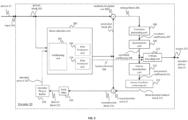
- Fig. 2 shows a schematic block diagram of an example video encoder 20 that is configured to implement the techniques of the present application.
- the video encoder 20 comprises an input 201 (or input interface 201), a residual calculation unit 204, a transform processing unit 206, a quantization unit 208, an inverse quantization unit 210, and inverse transform processing unit 212, a reconstruction unit 214, a loop filter unit 220, a decoded picture buffer (DPB) 230, a mode selection unit 260, an entropy encoding unit 270 and an output 272 (or output interface 272).
- the mode selection unit 260 may include an inter prediction unit 244, an intra prediction unit 254 and a partitioning unit 262.
- Inter prediction unit 244 may include a motion estimation unit and a motion compensation unit (not shown).
- a video encoder 20 as shown in Fig. 2 may also be referred to as hybrid video encoder or a video encoder according to a hybrid video codec.
- the residual calculation unit 204, the transform processing unit 206, the quantization unit 208, the mode selection unit 260 may be referred to as forming a forward signal path of the encoder 20, whereas the inverse quantization unit 210, the inverse transform processing unit 212, the reconstruction unit 214, the buffer 216, the loop filter 220, the decoded picture buffer (DPB) 230, the inter prediction unit 244 and the intra-prediction unit 254 may be referred to as forming a backward signal path of the video encoder 20, wherein the backward signal path of the video encoder 20 corresponds to the signal path of the decoder (see video decoder 30 in Fig. 3 ).
- the inverse quantization unit 210, the inverse transform processing unit 212, the reconstruction unit 214, the loop filter 220, the decoded picture buffer (DPB) 230, the inter prediction unit 244 and the intra-prediction unit 254 are also referred to forming the "built-in decoder" of video encoder 20.
- the encoder 20 may be configured to receive, e.g. via input 201, a picture 17 (or picture data 17), e.g. picture of a sequence of pictures forming a video or video sequence.
- the received picture or picture data may also be a pre-processed picture 19 (or pre-processed picture data 19).
- the picture 17 may also be referred to as current picture or picture to be coded (in particular in video coding to distinguish the current picture from other pictures, e.g. previously encoded and/or decoded pictures of the same video sequence, i.e. the video sequence which also comprises the current picture).
- a (digital) picture is or can be regarded as a two-dimensional array or matrix of samples with intensity values.
- a sample in the array may also be referred to as pixel (short form of picture element) or a pel.
- the number of samples in horizontal and vertical direction (or axis) of the array or picture define the size and/or resolution of the picture.
- typically three color components are employed, i.e. the picture may be represented or include three sample arrays.
- RBG format or color space a picture comprises a corresponding red, green and blue sample array.
- each pixel is typically represented in a luminance and chrominance format or color space, e.g.
- YCbCr which comprises a luminance component indicated by Y (sometimes also L is used instead) and two chrominance components indicated by Cb and Cr.
- the luminance (or short luma) component Y represents the brightness or grey level intensity (e.g. like in a grey-scale picture), while the two chrominance (or short chroma) components Cb and Cr represent the chromaticity or color information components.
- a picture in YCbCr format comprises a luminance sample array of luminance sample values (Y), and two chrominance sample arrays of chrominance values (Cb and Cr).
- Pictures in RGB format may be converted or transformed into YCbCr format and vice versa, the process is also known as color transformation or conversion.
- a picture may comprise only a luminance sample array. Accordingly, a picture may be, for example, an array of luma samples in monochrome format or an array of luma samples and two corresponding arrays of chroma samples in 4:2:0, 4:2:2, and 4:4:4 colour format.
- Embodiments of the video encoder 20 may comprise a picture partitioning unit (not depicted in Fig. 2 ) configured to partition the picture 17 into a plurality of (typically non-overlapping) picture blocks 203. These blocks may also be referred to as root blocks, macro blocks (H.264/AVC) or coding tree blocks (CTB) or coding tree units (CTU) (H.265/HEVC and VVC).
- the picture partitioning unit may be configured to use the same block size for all pictures of a video sequence and the corresponding grid defining the block size, or to change the block size between pictures or subsets or groups of pictures, and partition each picture into the corresponding blocks.
- the video encoder may be configured to receive directly a block 203 of the picture 17, e.g. one, several or all blocks forming the picture 17.
- the picture block 203 may also be referred to as current picture block or picture block to be coded.
- the picture block 203 again is or can be regarded as a two-dimensional array or matrix of samples with intensity values (sample values), although of smaller dimension than the picture 17.
- the block 203 may comprise, e.g., one sample array (e.g. a luma array in case of a monochrome picture 17, or a luma or chroma array in case of a color picture) or three sample arrays (e.g. a luma and two chroma arrays in case of a color picture 17) or any other number and/or kind of arrays depending on the color format applied.
- the number of samples in horizontal and vertical direction (or axis) of the block 203 define the size of block 203.
- a block may, for example, an MxN (M-column by N-row) array of samples, or an MxN array of transform coefficients.
- Embodiments of the video encoder 20 as shown in Fig. 2 may be configured to encode the picture 17 block by block, e.g. the encoding and prediction is performed per block 203.
- Embodiments of the video encoder 20 as shown in Fig. 2 may be further configured to partition and/or encode the picture by using slices (also referred to as video slices), wherein a picture may be partitioned into or encoded using one or more slices (typically non-overlapping), and each slice may comprise one or more blocks (e.g. CTUs).
- slices also referred to as video slices
- each slice may comprise one or more blocks (e.g. CTUs).
- Embodiments of the video encoder 20 as shown in Fig. 2 may be further configured to partition and/or encode the picture by using tile groups (also referred to as video tile groups) and/or tiles (also referred to as video tiles), wherein a picture may be partitioned into or encoded using one or more tile groups (typically non-overlapping), and each tile group may comprise, e.g. one or more blocks (e.g. CTUs) or one or more tiles, wherein each tile, e.g. may be of rectangular shape and may comprise one or more blocks (e.g. CTUs), e.g. complete or fractional blocks.
- tile groups also referred to as video tile groups
- tiles also referred to as video tiles
- each tile group may comprise, e.g. one or more blocks (e.g. CTUs) or one or more tiles, wherein each tile, e.g. may be of rectangular shape and may comprise one or more blocks (e.g. CTUs), e.g. complete or fractional blocks.
- the residual calculation unit 204 may be configured to calculate a residual block 205 (also referred to as residual 205) based on the picture block 203 and a prediction block 265 (further details about the prediction block 265 are provided later), e.g. by subtracting sample values of the prediction block 265 from sample values of the picture block 203, sample by sample (pixel by pixel) to obtain the residual block 205 in the sample domain.
- a residual block 205 also referred to as residual 205
- a prediction block 265 further details about the prediction block 265 are provided later
- the transform processing unit 206 may be configured to apply a transform, e.g. a discrete cosine transform (DCT) or discrete sine transform (DST), on the sample values of the residual block 205 to obtain transform coefficients 207 in a transform domain.
- a transform e.g. a discrete cosine transform (DCT) or discrete sine transform (DST)
- DCT discrete cosine transform
- DST discrete sine transform
- the transform processing unit 206 may be configured to apply integer approximations of DCT/DST, such as the transforms specified for H.265/HEVC. Compared to an orthogonal DCT transform, such integer approximations are typically scaled by a certain factor. In order to preserve the norm of the residual block which is processed by forward and inverse transforms, additional scaling factors are applied as part of the transform process.
- the scaling factors are typically chosen based on certain constraints like scaling factors being a power of two for shift operations, bit depth of the transform coefficients, tradeoff between accuracy and implementation costs, etc. Specific scaling factors are, for example, specified for the inverse transform, e.g. by inverse transform processing unit 212 (and the corresponding inverse transform, e.g. by inverse transform processing unit 312 at video decoder 30) and corresponding scaling factors for the forward transform, e.g. by transform processing unit 206, at an encoder 20 may be specified accordingly.
- Embodiments of the video encoder 20 may be configured to output transform parameters, e.g. a type of transform or transforms, e.g. directly or encoded or compressed via the entropy encoding unit 270, so that, e.g., the video decoder 30 may receive and use the transform parameters for decoding.
- transform parameters e.g. a type of transform or transforms, e.g. directly or encoded or compressed via the entropy encoding unit 270, so that, e.g., the video decoder 30 may receive and use the transform parameters for decoding.
- the quantization unit 208 may be configured to quantize the transform coefficients 207 to obtain quantized coefficients 209, e.g. by applying scalar quantization or vector quantization.
- the quantized coefficients 209 may also be referred to as quantized transform coefficients 209 or quantized residual coefficients 209.
- the quantization process may reduce the bit depth associated with some or all of the transform coefficients 207. For example, an n-bit transform coefficient may be rounded down to an m-bit Transform coefficient during quantization, where n is greater than m.
- the degree of quantization may be modified by adjusting a quantization parameter (QP). For example for scalar quantization, different scaling may be applied to achieve finer or coarser quantization. Smaller quantization step sizes correspond to finer quantization, whereas larger quantization step sizes correspond to coarser quantization.
- the applicable quantization step size may be indicated by a quantization parameter (QP).
- the quantization parameter may for example be an index to a predefined set of applicable quantization step sizes.
- small quantization parameters may correspond to fine quantization (small quantization step sizes) and large quantization parameters may correspond to coarse quantization (large quantization step sizes) or vice versa.
- the quantization may include division by a quantization step size and a corresponding and/or the inverse dequantization, e.g. by inverse quantization unit 210, may include multiplication by the quantization step size.
- Embodiments according to some standards, e.g. HEVC may be configured to use a quantization parameter to determine the quantization step size.
- the quantization step size may be calculated based on a quantization parameter using a fixed point approximation of an equation including division.
- Additional scaling factors may be introduced for quantization and dequantization to restore the norm of the residual block, which might get modified because of the scaling used in the fixed point approximation of the equation for quantization step size and quantization parameter.
- the scaling of the inverse transform and dequantization might be combined.
- customized quantization tables may be used and signaled from an encoder to a decoder, e.g. in a bitstream.
- the quantization is a lossy operation, wherein the loss increases with increasing quantization step sizes.
- Embodiments of the video encoder 20 may be configured to output quantization parameters (QP), e.g. directly or encoded via the entropy encoding unit 270, so that, e.g., the video decoder 30 may receive and apply the quantization parameters for decoding.
- QP quantization parameters
- the inverse quantization unit 210 is configured to apply the inverse quantization of the quantization unit 208 on the quantized coefficients to obtain dequantized coefficients 211, e.g. by applying the inverse of the quantization scheme applied by the quantization unit 208 based on or using the same quantization step size as the quantization unit 208.
- the dequantized coefficients 211 may also be referred to as dequantized residual coefficients 211 and correspond - although typically not identical to the transform coefficients due to the loss by quantization - to the transform coefficients 207.
- the inverse transform processing unit 212 is configured to apply the inverse transform of the transform applied by the transform processing unit 206, e.g. an inverse discrete cosine transform (DCT) or inverse discrete sine transform (DST) or other inverse transforms, to obtain a reconstructed residual block 213 (or corresponding dequantized coefficients 213) in the sample domain.
- the reconstructed residual block 213 may also be referred to as transform block 213.
- the reconstruction unit 214 (e.g. adder or summer 214) is configured to add the transform block 213 (i.e. reconstructed residual block 213) to the prediction block 265 to obtain a reconstructed block 215 in the sample domain, e.g. by adding - sample by sample - the sample values of the reconstructed residual block 213 and the sample values of the prediction block 265.
- the loop filter unit 220 (or short "loop filter” 220), is configured to filter the reconstructed block 215 to obtain a filtered block 221, or in general, to filter reconstructed samples to obtain filtered samples.
- the loop filter unit is, e.g., configured to smooth pixel transitions, or otherwise improve the video quality.
- the loop filter unit 220 may comprise one or more loop filters such as a de-blocking filter, a sample-adaptive offset (SAO) filter or one or more other filters, e.g. a bilateral filter, an adaptive loop filter (ALF), a sharpening, a smoothing filters or a collaborative filters, or any combination thereof.
- the loop filter unit 220 is shown in FIG. 2 as being an in loop filter, in other configurations, the loop filter unit 220 may be implemented as a post loop filter.
- the filtered block 221 may also be referred to as filtered reconstructed block 221.
- Embodiments of the video encoder 20 may be configured to output loop filter parameters (such as sample adaptive offset information), e.g. directly or encoded via the entropy encoding unit 270, so that, e.g., a decoder 30 may receive and apply the same loop filter parameters or respective loop filters for decoding.
- loop filter parameters such as sample adaptive offset information
- the decoded picture buffer (DPB) 230 may be a memory that stores reference pictures, or in general reference picture data, for encoding video data by video encoder 20.
- the DPB 230 may be formed by any of a variety of memory devices, such as dynamic random access memory (DRAM), including synchronous DRAM (SDRAM), magnetoresistive RAM (MRAM), resistive RAM (RRAM), or other types of memory devices.
- DRAM dynamic random access memory
- SDRAM synchronous DRAM
- MRAM magnetoresistive RAM
- RRAM resistive RAM
- the decoded picture buffer (DPB) 230 may be configured to store one or more filtered blocks 221.
- the decoded picture buffer 230 may be further configured to store other previously filtered blocks, e.g. previously reconstructed and filtered blocks 221, of the same current picture or of different pictures, e.g.
- the decoded picture buffer (DPB) 230 may be also configured to store one or more unfiltered reconstructed blocks 215, or in general unfiltered reconstructed samples, e.g. if the reconstructed block 215 is not filtered by loop filter unit 220, or any other further processed version of the reconstructed blocks or samples.
- the mode selection unit 260 comprises partitioning unit 262, inter-prediction unit 244 and intra-prediction unit 254, and is configured to receive or obtain original picture data, e.g. an original block 203 (current block 203 of the current picture 17), and reconstructed picture data, e.g. filtered and/or unfiltered reconstructed samples or blocks of the same (current) picture and/or from one or a plurality of previously decoded pictures, e.g. from decoded picture buffer 230 or other buffers (e.g. line buffer, not shown).
- the reconstructed picture data is used as reference picture data for prediction, e.g. inter-prediction or intra-prediction, to obtain a prediction block 265 or predictor 265.
- Mode selection unit 260 may be configured to determine or select a partitioning for a current block prediction mode (including no partitioning) and a prediction mode (e.g. an intra or inter prediction mode) and generate a corresponding prediction block 265, which is used for the calculation of the residual block 205 and for the reconstruction of the reconstructed block 215.
- a prediction mode e.g. an intra or inter prediction mode
- Embodiments of the mode selection unit 260 may be configured to select the partitioning and the prediction mode (e.g. from those supported by or available for mode selection unit 260), which provide the best match or in other words the minimum residual (minimum residual means better compression for transmission or storage), or a minimum signaling overhead (minimum signaling overhead means better compression for transmission or storage), or which considers or balances both.
- the mode selection unit 260 may be configured to determine the partitioning and prediction mode based on rate distortion optimization (RDO), i.e. select the prediction mode which provides a minimum rate distortion.
- RDO rate distortion optimization
- Terms like "best”, “minimum”, “optimum” etc. in this context do not necessarily refer to an overall “best”, “minimum”, “optimum”, etc. but may also refer to the fulfillment of a termination or selection criterion like a value exceeding or falling below a threshold or other constraints leading potentially to a "sub-optimum selection” but reducing complexity and processing time.
- the partitioning unit 262 may be configured to partition the block 203 into smaller block partitions or sub-blocks (which form again blocks), e.g. iteratively using quad-tree-partitioning (QT), binary partitioning (BT) or triple-tree-partitioning (TT) or any combination thereof, and to perform, e.g., the prediction for each of the block partitions or sub-blocks, wherein the mode selection comprises the selection of the tree-structure of the partitioned block 203 and the prediction modes are applied to each of the block partitions or sub-blocks.
- QT quad-tree-partitioning
- BT binary partitioning
- TT triple-tree-partitioning
- partitioning e.g. by partitioning unit 260
- prediction processing by inter-prediction unit 244 and intra-prediction unit 254
- the partitioning unit 262 may partition (or split) a current block 203 into smaller partitions, e.g. smaller blocks of square or rectangular size. These smaller blocks (which may also be referred to as sub-blocks) may be further partitioned into even smaller partitions.
- This is also referred to tree-partitioning or hierarchical tree-partitioning, wherein a root block, e.g. at root tree-level 0 (hierarchy-level 0, depth 0), may be recursively partitioned, e.g. partitioned into two or more blocks of a next lower tree-level, e.g.
- nodes at tree-level 1 (hierarchy-level 1, depth 1), wherein these blocks may be again partitioned into two or more blocks of a next lower level, e.g. tree-level 2 (hierarchy-level 2, depth 2), etc. until the partitioning is terminated, e.g. because a termination criterion is fulfilled, e.g. a maximum tree depth or minimum block size is reached.
- Blocks which are not further partitioned are also referred to as leaf-blocks or leaf nodes of the tree.
- a tree using partitioning into two partitions is referred to as binary-tree (BT)
- BT binary-tree
- TT ternary-tree
- QT quad-tree
- the term "block” as used herein may be a portion, in particular a square or rectangular portion, of a picture.
- the block may be or correspond to a coding tree unit (CTU), a coding unit (CU), prediction unit (PU), and transform unit (TU) and/or to the corresponding blocks, e.g. a coding tree block (CTB), a coding block (CB), a transform block (TB) or prediction block (PB).
- CTU coding tree unit
- CU coding unit
- PU prediction unit
- TU transform unit
- a coding tree block CB
- CB coding block
- TB transform block
- PB prediction block
- a coding tree unit may be or comprise a CTB of luma samples, two corresponding CTBs of chroma samples of a picture that has three sample arrays, or a CTB of samples of a monochrome picture or a picture that is coded using three separate colour planes and syntax structures used to code the samples.
- a coding tree block may be an NxN block of samples for some value of N such that the division of a component into CTBs is a partitioning.
- a coding unit may be or comprise a coding block of luma samples, two corresponding coding blocks of chroma samples of a picture that has three sample arrays, or a coding block of samples of a monochrome picture or a picture that is coded using three separate colour planes and syntax structures used to code the samples.
- a coding block may be an MxN block of samples for some values of M and N such that the division of a CTB into coding blocks is a partitioning.
- a coding tree unit may be split into CUs by using a quad-tree structure denoted as coding tree.
- the decision whether to code a picture area using inter-picture (temporal) or intra-picture (spatial) prediction is made at the CU level.
- Each CU can be further split into one, two or four PUs according to the PU splitting type. Inside one PU, the same prediction process is applied and the relevant information is transmitted to the decoder on a PU basis.
- a CU can be partitioned into transform units (TLTs) according to another quadtree structure similar to the coding tree for the CU.
- TLTs transform units
- a combined Quad-tree and binary tree (QTBT) partitioning is for example used to partition a coding block.
- a CU can have either a square or rectangular shape.
- a coding tree unit (CTU) is first partitioned by a quadtree structure.
- the quadtree leaf nodes are further partitioned by a binary tree or ternary (or triple) tree structure.
- the partitioning tree leaf nodes are called coding units (CUs), and that segmentation is used for prediction and transform processing without any further partitioning.
- CUs coding units
- multiple partition for example, triple tree partition may be used together with the QTBT block structure.
- the mode selection unit 260 of video encoder 20 may be configured to perform any combination of the partitioning techniques described herein.
- the video encoder 20 is configured to determine or select the best or an optimum prediction mode from a set of (e.g. pre-determined) prediction modes.
- the set of prediction modes may comprise, e.g., intra-prediction modes and/or inter-prediction modes.
- the set of intra-prediction modes may comprise 35 different intra-prediction modes, e.g. non-directional modes like DC (or mean) mode and planar mode, or directional modes, e.g. as defined in HEVC, or may comprise 67 different intra-prediction modes, e.g. non-directional modes like DC (or mean) mode and planar mode, or directional modes, e.g. as defined for VVC.
- intra-prediction modes e.g. non-directional modes like DC (or mean) mode and planar mode
- directional modes e.g. as defined for VVC.
- the intra-prediction unit 254 is configured to use reconstructed samples of neighboring blocks of the same current picture to generate an intra-prediction block 265 according to an intra-prediction mode of the set of intra-prediction modes.
- the intra prediction unit 254 (or in general the mode selection unit 260) is further configured to output intra-prediction parameters (or in general information indicative of the selected intra prediction mode for the block) to the entropy encoding unit 270 in form of syntax elements 266 for inclusion into the encoded picture data 21, so that, e.g., the video decoder 30 may receive and use the prediction parameters for decoding.
- the set of (or possible) inter-prediction modes depends on the available reference pictures (i.e. previous at least partially decoded pictures, e.g. stored in DBP 230) and other inter-prediction parameters, e.g. whether the whole reference picture or only a part, e.g. a search window area around the area of the current block, of the reference picture is used for searching for a best matching reference block, and/or e.g. whether pixel interpolation is applied, e.g. half/semi-pel and/or quarter-pel interpolation, or not.
- other inter-prediction parameters e.g. whether the whole reference picture or only a part, e.g. a search window area around the area of the current block, of the reference picture is used for searching for a best matching reference block, and/or e.g. whether pixel interpolation is applied, e.g. half/semi-pel and/or quarter-pel interpolation, or not.
- skip mode and/or direct mode may be applied.
- the inter prediction unit 244 may include a motion estimation (ME) unit and a motion compensation (MC) unit (both not shown in Fig.2 ).
- the motion estimation unit may be configured to receive or obtain the picture block 203 (current picture block 203 of the current picture 17) and a decoded picture 231, or at least one or a plurality of previously reconstructed blocks, e.g. reconstructed blocks of one or a plurality of other/different previously decoded pictures 231, for motion estimation.
- a video sequence may comprise the current picture and the previously decoded pictures 231, or in other words, the current picture and the previously decoded pictures 231 may be part of or form a sequence of pictures forming a video sequence.
- the encoder 20 may, e.g., be configured to select a reference block from a plurality of reference blocks of the same or different pictures of the plurality of other pictures and provide a reference picture (or reference picture index) and/or an offset (spatial offset) between the position (x, y coordinates) of the reference block and the position of the current block as inter prediction parameters to the motion estimation unit.
- This offset is also called motion vector (MV).
- the motion compensation unit is configured to obtain, e.g. receive, an inter prediction parameter and to perform inter prediction based on or using the inter prediction parameter to obtain an inter prediction block 265.
- Motion compensation performed by the motion compensation unit, may involve fetching or generating the prediction block based on the motion/block vector determined by motion estimation, possibly performing interpolations to sub-pixel precision. Interpolation filtering may generate additional pixel samples from known pixel samples, thus potentially increasing the number of candidate prediction blocks that may be used to code a picture block.
- the motion compensation unit may locate the prediction block to which the motion vector points in one of the reference picture lists.
- the motion compensation unit may also generate syntax elements associated with the blocks and video slices for use by video decoder 30 in decoding the picture blocks of the video slice.
- syntax elements associated with the blocks and video slices for use by video decoder 30 in decoding the picture blocks of the video slice.
- tile groups and/or tiles and respective syntax elements may be generated or used.
- the entropy encoding unit 270 is configured to apply, for example, an entropy encoding algorithm or scheme (e.g. a variable length coding (VLC) scheme, an context adaptive VLC scheme (CAVLC), an arithmetic coding scheme, a binarization, a context adaptive binary arithmetic coding (CABAC), syntax-based context-adaptive binary arithmetic coding (SBAC), probability interval partitioning entropy (PIPE) coding or another entropy encoding methodology or technique) or bypass (no compression) on the quantized coefficients 209, inter prediction parameters, intra prediction parameters, loop filter parameters and/or other syntax elements to obtain encoded picture data 21 which can be output via the output 272, e.g.
- an entropy encoding algorithm or scheme e.g. a variable length coding (VLC) scheme, an context adaptive VLC scheme (CAVLC), an arithmetic coding scheme, a binarization, a context adaptive binary a
- the encoded bitstream 21 may be transmitted to video decoder 30, or stored in a memory for later transmission or retrieval by video decoder 30.
- a non-transform based encoder 20 can quantize the residual signal directly without the transform processing unit 206 for certain blocks or frames.
- an encoder 20 can have the quantization unit 208 and the inverse quantization unit 210 combined into a single unit.
- Fig. 3 shows an example of a video decoder 30 that is configured to implement the techniques of this present application.
- the video decoder 30 is configured to receive encoded picture data 21 (e.g. encoded bitstream 21), e.g. encoded by encoder 20, to obtain a decoded picture 331.
- the encoded picture data or bitstream comprises information for decoding the encoded picture data, e.g. data that represents picture blocks of an encoded video slice (and/or tile groups or tiles) and associated syntax elements.
- the decoder 30 comprises an entropy decoding unit 304, an inverse quantization unit 310, an inverse transform processing unit 312, a reconstruction unit 314 (e.g. a summer 314), a loop filter 320, a decoded picture buffer (DBP) 330, a mode application unit 360, an inter prediction unit 344 and an intra prediction unit 354.
- Inter prediction unit 344 may be or include a motion compensation unit.
- Video decoder 30 may, in some examples, perform a decoding pass generally reciprocal to the encoding pass described with respect to video encoder 100 from FIG. 2 .
- the inverse quantization unit 210 may be identical in function to the inverse quantization unit 110
- the inverse transform processing unit 312 may be identical in function to the inverse transform processing unit 212
- the reconstruction unit 314 may be identical in function to reconstruction unit 214
- the loop filter 320 may be identical in function to the loop filter 220
- the decoded picture buffer 330 may be identical in function to the decoded picture buffer 230. Therefore, the explanations provided for the respective units and functions of the video 20 encoder apply correspondingly to the respective units and functions of the video decoder 30.
- the entropy decoding unit 304 is configured to parse the bitstream 21 (or in general encoded picture data 21) and perform, for example, entropy decoding to the encoded picture data 21 to obtain, e.g., quantized coefficients 309 and/or decoded coding parameters (not shown in Fig. 3 ), e.g. any or all of inter prediction parameters (e.g. reference picture index and motion vector), intra prediction parameter (e.g. intra prediction mode or index), transform parameters, quantization parameters, loop filter parameters, and/or other syntax elements.
- Entropy decoding unit 304 maybe configured to apply the decoding algorithms or schemes corresponding to the encoding schemes as described with regard to the entropy encoding unit 270 of the encoder 20.
- Entropy decoding unit 304 may be further configured to provide inter prediction parameters, intra prediction parameter and/or other syntax elements to the mode application unit 360 and other parameters to other units of the decoder 30.
- Video decoder 30 may receive the syntax elements at the video slice level and/or the video block level. In addition or as an alternative to slices and respective syntax elements, tile groups and/or tiles and respective syntax elements may be received and/or used.
- the inverse quantization unit 310 may be configured to receive quantization parameters (QP) (or in general information related to the inverse quantization) and quantized coefficients from the encoded picture data 21 (e.g. by parsing and/or decoding, e.g. by entropy decoding unit 304) and to apply based on the quantization parameters an inverse quantization on the decoded quantized coefficients 309 to obtain dequantized coefficients 311, which may also be referred to as transform coefficients 311.
- the inverse quantization process may include use of a quantization parameter determined by video encoder 20 for each video block in the video slice (or tile or tile group) to determine a degree of quantization and, likewise, a degree of inverse quantization that should be applied.
- Inverse transform processing unit 312 may be configured to receive dequantized coefficients 311, also referred to as transform coefficients 311, and to apply a transform to the dequantized coefficients 311 in order to obtain reconstructed residual blocks 213 in the sample domain.
- the reconstructed residual blocks 213 may also be referred to as transform blocks 313.
- the transform may be an inverse transform, e.g., an inverse DCT, an inverse DST, an inverse integer transform, or a conceptually similar inverse transform process.
- the inverse transform processing unit 312 may be further configured to receive transform parameters or corresponding information from the encoded picture data 21 (e.g. by parsing and/or decoding, e.g. by entropy decoding unit 304) to determine the transform to be applied to the dequantized coefficients 311.
- the reconstruction unit 314 (e.g. adder or summer 314) may be configured to add the reconstructed residual block 313, to the prediction block 365 to obtain a reconstructed block 315 in the sample domain, e.g. by adding the sample values of the reconstructed residual block 313 and the sample values of the prediction block 365.
- the loop filter unit 320 (either in the coding loop or after the coding loop) is configured to filter the reconstructed block 315 to obtain a filtered block 321, e.g. to smooth pixel transitions, or otherwise improve the video quality.
- the loop filter unit 320 may comprise one or more loop filters such as a de-blocking filter, a sample-adaptive offset (SAO) filter or one or more other filters, e.g. a bilateral filter, an adaptive loop filter (ALF), a sharpening, a smoothing filters or a collaborative filters, or any combination thereof.
- the loop filter unit 320 is shown in FIG. 3 as being an in loop filter, in other configurations, the loop filter unit 320 may be implemented as a post loop filter.
- decoded video blocks 321 of a picture are then stored in decoded picture buffer 330, which stores the decoded pictures 331 as reference pictures for subsequent motion compensation for other pictures and/or for output respectively display.
- the decoder 30 is configured to output the decoded picture 311, e.g. via output 312, for presentation or viewing to a user.
- the inter prediction unit 344 may be identical to the inter prediction unit 244 (in particular to the motion compensation unit) and the intra prediction unit 354 may be identical to the inter prediction unit 254 in function, and performs split or partitioning decisions and prediction based on the partitioning and/or prediction parameters or respective information received from the encoded picture data 21 (e.g. by parsing and/or decoding, e.g. by entropy decoding unit 304).
- Mode application unit 360 may be configured to perform the prediction (intra or inter prediction) per block based on reconstructed pictures, blocks or respective samples (filtered or unfiltered) to obtain the prediction block 365.
- intra prediction unit 354 of mode application unit 360 is configured to generate prediction block 365 for a picture block of the current video slice based on a signaled intra prediction mode and data from previously decoded blocks of the current picture.
- inter prediction unit 344 e.g. motion compensation unit
- the prediction blocks may be produced from one of the reference pictures within one of the reference picture lists.
- Video decoder 30 may construct the reference frame lists, List 0 and List 1, using default construction techniques based on reference pictures stored in DPB 330.
- the same or similar may be applied for or by embodiments using tile groups (e.g. video tile groups) and/or tiles (e.g. video tiles) in addition or alternatively to slices (e.g. video slices), e.g. a video may be coded using I, P or B tile groups and /or tiles.
- Mode application unit 360 is configured to determine the prediction information for a video block of the current video slice by parsing the motion vectors or related information and other syntax elements, and uses the prediction information to produce the prediction blocks for the current video block being decoded. For example, the mode application unit 360 uses some of the received syntax elements to determine a prediction mode (e.g., intra or inter prediction) used to code the video blocks of the video slice, an inter prediction slice type (e.g., B slice, P slice, or GPB slice), construction information for one or more of the reference picture lists for the slice, motion vectors for each inter encoded video block of the slice, inter prediction status for each inter coded video block of the slice, and other information to decode the video blocks in the current video slice.
- a prediction mode e.g., intra or inter prediction
- an inter prediction slice type e.g., B slice, P slice, or GPB slice
- construction information for one or more of the reference picture lists for the slice motion vectors for each inter encoded video block of the slice, inter prediction status for each
- tile groups e.g. video tile groups
- tiles e.g. video tiles
- slices e.g. video slices
- Embodiments of the video decoder 30 as shown in Fig. 3 may be configured to partition and/or decode the picture by using slices (also referred to as video slices), wherein a picture may be partitioned into or decoded using one or more slices (typically non-overlapping), and each slice may comprise one or more blocks (e.g. CTUs).
- slices also referred to as video slices
- each slice may comprise one or more blocks (e.g. CTUs).
- Embodiments of the video decoder 30 as shown in Fig. 3 may be configured to partition and/or decode the picture by using tile groups (also referred to as video tile groups) and/or tiles (also referred to as video tiles), wherein a picture may be partitioned into or decoded using one or more tile groups (typically non-overlapping), and each tile group may comprise, e.g. one or more blocks (e.g. CTUs) or one or more tiles, wherein each tile, e.g. may be of rectangular shape and may comprise one or more blocks (e.g. CTUs), e.g. complete or fractional blocks.
- tile groups also referred to as video tile groups
- tiles also referred to as video tiles
- each tile group may comprise, e.g. one or more blocks (e.g. CTUs) or one or more tiles, wherein each tile, e.g. may be of rectangular shape and may comprise one or more blocks (e.g. CTUs), e.g. complete or fractional blocks.
- the video decoder 30 can be used to decode the encoded picture data 21.
- the decoder 30 can produce the output video stream without the loop filtering unit 320.
- a non-transform based decoder 30 can inverse-quantize the residual signal directly without the inverse-transform processing unit 312 for certain blocks or frames.
- the video decoder 30 can have the inverse-quantization unit 310 and the inverse-transform processing unit 312 combined into a single unit.
- a processing result of a current step may be further processed and then output to the next step.
- a further operation such as Clip or shift, may be performed on the processing result of the interpolation filtering, motion vector derivation or loop filtering.
- the value of motion vector is constrained to a predefined range according to its representing bit. If the representing bit of motion vector is bitDepth, then the range is -2 ⁇ (bitDepth-1) ⁇ 2 ⁇ (bitDepth-1)-1, where " ⁇ " means exponentiation. For example, if bitdepth is set equal to 16, the range is -32768 ⁇ 32767; if bitdepth is set equal to 18, the range is -131072-131071.
- the value of the derived motion vector (e.g. the MVs of four 4x4 sub-blocks within one 8x8 block) is constrained such that the max difference between integer parts of the four 4x4 sub-block MVs is no more than N pixels, such as no more than 1 pixel.
- N pixels such as no more than 1 pixel.
- mvx is a horizontal component of a motion vector of an image block or a sub-block
- mvy is a vertical component of a motion vector of an image block or a sub-block
- ux and uy indicates an intermediate value
- the operations may be applied during the sum of mvp and mvd, as shown in formula (5) to (8).
- vx is a horizontal component of a motion vector of an image block or a sub-block
- vy is a vertical component of a motion vector of an image block or a sub-block
- x, y and z respectively correspond to three input value of the MV clipping process
- FIG. 4 is a schematic diagram of a video coding device 400 according to an embodiment of the disclosure.
- the video coding device 400 is suitable for implementing the disclosed embodiments as described herein.
- the video coding device 400 may be a decoder such as video decoder 30 of FIG. 1A or an encoder such as video encoder 20 of FIG. 1A .
- the video coding device 400 comprises ingress ports 410 (or input ports 410) and receiver units (Rx) 420 for receiving data; a processor, logic unit, or central processing unit (CPU) 430 to process the data; transmitter units (Tx) 440 and egress ports 450 (or output ports 450) for transmitting the data; and a memory 460 for storing the data.
- the video coding device 400 may also comprise optical-to-electrical (OE) components and electrical-to-optical (EO) components coupled to the ingress ports 410, the receiver units 420, the transmitter units 440, and the egress ports 450 for egress or ingress of optical or electrical signals.
- OE optical-to-electrical
- EO electrical-to-optical
- the processor 430 is implemented by hardware and software.
- the processor 430 may be implemented as one or more CPU chips, cores (e.g., as a multi-core processor), FPGAs, ASICs, and DSPs.
- the processor 430 is in communication with the ingress ports 410, receiver units 420, transmitter units 440, egress ports 450, and memory 460.
- the processor 430 comprises a coding module 470.
- the coding module 470 implements the disclosed embodiments described above. For instance, the coding module 470 implements, processes, prepares, or provides the various coding operations. The inclusion of the coding module 470 therefore provides a substantial improvement to the functionality of the video coding device 400 and effects a transformation of the video coding device 400 to a different state.
- the coding module 470 is implemented as instructions stored in the memory 460 and executed by the processor 430.
- the memory 460 may comprise one or more disks, tape drives, and solid-state drives and may be used as an over-flow data storage device, to store programs when such programs are selected for execution, and to store instructions and data that are read during program execution.
- the memory 460 may be, for example, volatile and/or non-volatile and may be a read-only memory (ROM), random access memory (RAM), ternary content-addressable memory (TCAM), and/or static random-access memory (SRAM).
- Fig. 5 is a simplified block diagram of an apparatus 500 that may be used as either or both of the source device 12 and the destination device 14 from Fig. 1 according to an exemplary embodiment.
- a processor 502 in the apparatus 500 can be a central processing unit.
- the processor 502 can be any other type of device, or multiple devices, capable of manipulating or processing information now-existing or hereafter developed.
- the disclosed implementations can be practiced with a single processor as shown, e.g., the processor 502, advantages in speed and efficiency can be achieved using more than one processor.
- a memory 504 in the apparatus 500 can be a read only memory (ROM) device or a random access memory (RAM) device in an implementation. Any other suitable type of storage device can be used as the memory 504.
- the memory 504 can include code and data 506 that is accessed by the processor 502 using a bus 512.
- the memory 504 can further include an operating system 508 and application programs 510, the application programs 510 including at least one program that permits the processor 502 to perform the methods described here.
- the application programs 510 can include applications 1 through N, which further include a video coding application that performs the methods described here.
- the apparatus 500 can also include one or more output devices, such as a display 518.
- the display 518 may be, in one example, a touch sensitive display that combines a display with a touch sensitive element that is operable to sense touch inputs.
- the display 518 can be coupled to the processor 502 via the bus 512.
- the bus 512 of the apparatus 500 can be composed of multiple buses.
- the secondary storage 514 can be directly coupled to the other components of the apparatus 500 or can be accessed via a network and can comprise a single integrated unit such as a memory card or multiple units such as multiple memory cards.
- the apparatus 500 can thus be implemented in a wide variety of configurations.
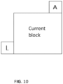
- a 6-MPM (Most Probable Modes) list is constructed for intra prediction mode coding.
- the MPM list is introduced to reduce bits required for coding the current block's intra prediction mode.
- the 6-MPM list is constructed based on intra prediction modes of neighboring blocks of the current block. When intra prediction mode of the current block falls into the MPM list, an index rather than actual mode is coded, which can use less bits. When the intra prediction mode of the current block doesn't fall into the MPM list, truncated binarization is used for coding the intra prediction mode of the current block.
- MPM list provides a good prediction for intra prediction mode of the current block.
- MRL Multiple Reference Line
- VTM 4.0 Multiple Reference Line
- MRL Multiple Reference Line
- a value of MRL line index i.e. the most close neighboring reference line is used, as shown in Fig. 6
- a normal 6 MPM list containing planar and DC is used.
- a value of MRL line index is not equal to 0
- a 6-MPM list excluding planar i.e. a value of 0
- DC i.e. a value of 1
- Intra sub-partition (ISP) coding mode is a tool newly adopted in VTM4.0 (JVET-M0102).
- Luma intra-predicted blocks are divided vertically or horizontally into 2 or 4 sub-partitions, depending on the block size dimensions, as shown in Table 1.
- Figure 7 and Figure 8 show examples of the two possibilities. All sub-partitions fulfill the condition of having at least 16 samples.
- Table 1 Number of sub-partitions depending on the block size Block Size Number of Sub-Partitions 4 ⁇ 4 Not divided 4 ⁇ 8 and 8 ⁇ 4 2 All other cases 4
- VTM 4.0 When intra sub-partition coding mode is enabled, another MPM list excluding DC mode is used in VTM 4.0.
- the intra sub-partition mode can be applied when a value of multiple reference line index equals to 0 (i.e. MRL is not applied to the current intra prediction block). All sub-partition shares a single intra prediction mode, therefore, the MPM list is constructed once for the intra block and shared by all sub-partitions.
- MPM might depends on the splitting mode of ISP. Two splitting modes are determined: horizontal or vertical. They are shown as in the figure 7 and Figure 8 , where horizontal splitting/partition is shown at the top, and vertical splitting/partition is shown at the bottom.
- Table 2 summarizes the characteristics of the 3 MPM list used in VTM 4.0.
- CABAC coding comprised of binarization, context modeling, and binary arithmetic coding.
- Binarization maps the syntax elements to binary symbols (bins).
- Context modeling estimates the probability of each non-bypassed (i.e., regular coded) bin based on some specific context.
- binary arithmetic coding compresses the bins to bits according to the estimated probability.
- each bin value is encoded by using the regular binary arithmetic coding engine, where the associated probability model is either determined by a fixed choice, based on the type of syntax element and the bin position or bin index (binIdx) in the binarized representation of the syntax element, or adaptively chosen from two or more probability models depending on the related side information.
- the associated coding mode decision can be either chosen as the regular or the bypass mode. The latter is chosen for bins, which are assumed to be uniformly distributed and for which, consequently, the whole regular binary arithmetic encoding (and decoding) process is simply bypassed.
- each bin value is encoded by using the regular binary arithmetic coding engine, where the associated probability model is either determined by a fixed choice, based on the type of syntax element and the bin position or bin index (binIdx) in the binarized representation of the syntax element, or adaptively chosen from two or more probability models depending on the related side information.
- Each probability model in CABAC is addressed using a unique context index (ctxldx), either determined by a fixed assignment or computed by the context derivation logic by which, in turn, the given context model is specified.
- the intra prediction mode coding of VVC depends on the intra prediction modes of its neighboring blocks. Namely The left and above blocks of the current block. Their position is shown in Figure 10 .
- a flag (i.e. MPM flag) is used to indicate whether the current block's intra prediction mode is in the MPM list or not.
- MPM flag i.e. a value of 1
- the intra prediction mode can be determined using a MPM index.
- the MPM index is coded using truncated unary code, as shown in the following Table 3 when the length of MPM list is 6.
- MPM flag is not true, the intra prediction mode of current block is not in the MPM list, and the mode is coded using truncated binary code.
- Another example of MPM index when the MPM list is comprised of 5 modes is shown in Table 4.
- the bin string for coding index is called truncated unary code (not truncated binary code for coding non-MPM modes). Note that for truncated unary code the bin 0 and 1 are interchangeable without loss of generality.
- the MPM index when the MPM list is comprised of 5 modes can also be coded as shown in Table 5.
- Table 3 MPM flag and MPM index coding when 6 entries in a MPM list Intra prediction modes MPM flag MPM index Bin string of MPM index MPM modes (6) 1 0 0 1 10 2 110 3 1110 4 11110 5 11111 0 Truncated binary (TB) code
- Table 4 MPM flag and MPM index coding, when 5 entries in a MPM list Intra prediction modes MPM flag MPM index Bin string of MPM index MPM modes (5) 1 0 0 1 10 2 110 3 1110 4 1111 0 Truncated binary (TB) code
- Table 5 MPM flag and MPM index coding, when 5 entries in a MPM list, and alternative codeword for MPM index Intra prediction modes MPM flag MPM index Bin string of MPM index MPM modes (5) 1 0 1 1 01 2 001 3 0001 4 0000 0 Truncated binary (TB) code
- Other intra prediction modes are called angular prediction modes.
- VTM4.0 the following syntax design, as shown in Table 6 is used for signaling intra prediction mode information.
- intra_luma_ref_idx[ x0 ][ y0 ] can have three values, 0, 1, or 2, indicates which reference line is used. When intra_luma_ref_idx[ x0 ][ y0 ] is not present it is inferred to be equal to 0.
- intra_subpartitions_mode_flag[ x0 ][ y0 ] 1 specifies that the current intra coding unit is further partitioned (i.e ISP mode is enabled).
- intra _subpartitions_mode_flag[ x0 ][ y0 ] 0 specifies that the current intra coding unit is not partitioned into rectangular transform block subpartitions.
- intra_subpartitions_mode_flag[ x0 ][ y0 ] is not present, it is inferred to be equal to 0.
- intra_luma_mpm_flag [ x0 ][ y0 ] specifies the intra prediction mode for luma samples.
- intra_luma_mpm_flag [ x0 ][ y0 ] indicates whether the intra prediction mode of the current block is derived from the MPM list or not.
- intra_luma_mpm_flag[ x0 ][ y0 ] indicates the intra prediction mode of the current block is derived from the MPM list; If the value of the intra_luma_mpm_flag [ x0 ][ y0 ] is 0, it indicates the intra prediction mode of the current block is not derived from the MPM list.
- intra_luma_mpm_flag[ x0 ][ y0 ] is not present, it is inferred to be equal to 1.
- intra_luma _mpm _flag[ x0 ][ y0 ] corresponds to MPM flag in Table 3.
- intra_luma_mpm_idx corresponds to MPM index in Table 3 and use truncated unary code as shown in Table 3.
- intra_luma_mpm_remainder represents truncated binary code of mode that is not in the MPM list.
- a syntax element intra_luma_planar_flag and ctx are disclosed.
- a flag intra_luma_planar_flag is introduced.
- the decoder parses an intra _luma_planar flag to determine whether an intra prediction mode of a current block is a Planar mode or not.
- the intra prediction mode of current block is a Planar mode.
- the intra_luma_planar_flag is 0, the intra prediction mode of current block is NOT a Planar mode.
- intra_luma_planar_flag is not present (for example, this flag can't be parsed from a bitstream in case intra_luma_mpm_flag is equal to 0), a value of the intra_luma_planar_flag is inferred as 0.
- IntraPredModeY[ xCb ][ yCb ] is derived by applying the following procedure:
- the decoder further parses a syntax element intra luma mpm idx.
- a value of the intra_luma_planar_flag is CABAC contexted coded (i.e. not CABAC by-pass coded), and decoder parses the flag using context based on whether current block is a normal intra block or not.
- a value of the intra_luma_planar_flag is CABAC contexted coded (i.e. not CABAC by-pass coded), and decoder parse the flag using context based on whether current block is an intra block with multiple reference line (MRL) enabled or not.
- CABAC contexted coded i.e. not CABAC by-pass coded
- a value of the intra_luma_planar_flag is CABAC contexted coded (i.e. not CABAC by-pass coded), and decoder parse the flag using context based on whether current block is an intra block with intra sub-partition (ISP) coding mode enabled or not.
- CABAC contexted coded i.e. not CABAC by-pass coded
- decoder parse the flag using context based on whether current block is an intra block with intra sub-partition (ISP) coding mode enabled or not.
- ISP intra sub-partition
- Embodiment 2 intra_luma_not_planar_flag and ctx According to one embodiment of the invention, a syntax element intra_luma_not_planar_flag is introduced.
- the decoder parses intra_luma_not_planar_flag to determine whether the intra prediction mode of current block is a Planar mode or not.
- a value of the intra_luma_not_planar_flag is 1, the intra prediction mode of current block is NOT a Planar mode;
- a value of the intra_luma_not_planar_flag is 0, the intra prediction mode of current block is a Planar mode.
- intra_luma_not_planar_flag is not present in a bitstream, a value of the intra_luma_not_planar_flag is inferred as 1.
- the position of intra_luma_not_planar_flag is placed as in Table 8.
- an intra prediction mode of a current block is not a planar mode (i.e a value of the intra_luma_not_planar_flag is 1)
- the decoder further parses a syntax element intra luma_mpm_idx.
- the intra prediction mode of the current block IntraPredModeY[ xCb ][ yCb ] is derived by applying the following procedure:
- a value of the intra_luma_not_planar_flag is CABAC contexted coded (i.e. not CABAC by-pass coded), and decoder parse the flag using context based on whether current block is a normal intra block or not.
- a value of the intra_luma_not_planar_flag is CABAC contexted coded (i.e. not CABAC by-pass coded), and decoder parse the flag using context based on whether current block is an intra block with multiple reference line (MRL) enabled or not.
- CABAC contexted coded i.e. not CABAC by-pass coded
- a value of the intra_luma_not_planar_flag is CABAC contexted coded (i.e. not CABAC by-pass coded), and decoder parse the flag using context based on whether current block is an intra block with intra sub-partition (ISP) coding mode enabled or not.
- CABAC contexted coded i.e. not CABAC by-pass coded
- decoder parse the flag using context based on whether current block is an intra block with intra sub-partition (ISP) coding mode enabled or not.
- ISP intra sub-partition
- a flag intra_luma_planar_flag is introduced.
- the decoder parses whether a value of the reference index line (( intra_luma_ref_idx ) is 0 or not. If a value of the reference index line is 0, a value of the intra_luma_planar_flag is parsed to determine whether the intra prediction mode of current block is a Planar mode or not. When a value of the intra_luma_planar_flag is 1, the intra prediction mode of current block is a Planar mode. When a value of the intra_luma_planar_flag is 0, the intra prediction mode of current block is NOT a Planar mode. If intra_luma_planar_flag is not present, a value of the intra_luma_planar_flag is inferred as 0.
- the decoder further parses intra_luma_mpm_idx.
- a value of the intra_luma_planar_flag is CABAC by-pass coded (i.e. not CABAC contexted coded), and decoder parse the flag without using any CABAC context.
- intra_luma_planar_flag The position of intra_luma_planar_flag is placed as in Table 9.
- a flag intra_luma_not_planar_flag is introduced.
- intra_luma_mpm_flag a value of the intra_luma_mpm_flag
- the decoder parses whether a value of the reference index line is 0 or not. If a value of the reference index line is 0, intra_luma_not_planar_flag is parsed to determine whether the intra prediction mode of current block is a Planar mode or not. When a value of the intra_luma_not_planar_flag is 1 , the intra prediction mode of current block is NOT a Planar mode. When a value of the intra_luma_planar_flag is 0, the intra prediction mode of current block is a Planar mode. If intra_luma_not_planar_flag is not present, a value of the intra_luma_not_planar_flag is inferred as 1.
- an intra prediction mode of a current block is not a planar mode (i.e a value of the intra_luma_not_planar_flag is 1)
- the decoder further parses intra_luma_mpm_idx.
- a value of the intra_luma_not_planar_flag is CABAC by-pass coded (i.e. not CABAC context coded), and decoder parse the flag without using any CABAC context.
- intra_not_luma_planar_flag The position of intra_not_luma_planar_flag is placed as in Table 10.
- Embodiment 5 intra_luma_not _planar_flag and MRL, and cabac contexted coded (the difference to embodiment 4 is that intra_luma_not_planar_flag is cabac context coded instead of by-pass coded).
- a flag intra_luma_not_planar_flag is introduced.
- the decoder parses whether a value of the reference index line is 0 or not. If a value of the reference index line is 0, intra_luma_not_planar_flag is parsed to determine whether the intra prediction mode of current block is a Planar mode or not. When a value of the intra_luma_not_planar_flag is 1, the intra prediction mode of current block is NOT a Planar mode. When a value of the intra_luma_planar_flag is 0, the intra prediction mode of current block is a Planar mode. If intra_luma_not _ planar_flag is not present, a value of the intra_luma_not _ planar_flag is inferred as 1.
- an intra prediction mode of a current block is not a planar mode (i.e., a value of the intra_luma_not_planar_flag is 1)
- the decoder further parses intra_luma_mpm_idx.
- a value of the intra_luma_not_planar_flag is CABAC contexted coded (i.e. not CABAC by-pass coded), and decoder parse the flag using context based on whether current block is a normal intra block or not.
- a value of the intra_luma_not_planar_flag is CABAC contexted coded (i.e. not CABAC by-pass coded), and decoder parse the flag using context based on whether current block is an intra block with multiple reference line (MRL) enabled or not.
- CABAC contexted coded i.e. not CABAC by-pass coded
- a value of the intra_luma_not_planar_flag is CABAC contexted coded (i.e. not CABAC by-pass coded), and decoder parse the flag using context based on whether current block is an intra block with intra sub-partition (ISP) coding mode enabled or not.
- CABAC contexted coded i.e. not CABAC by-pass coded
- decoder parse the flag using context based on whether current block is an intra block with intra sub-partition (ISP) coding mode enabled or not.
- ISP intra sub-partition
- intra_luma_not_planar_flag[ x0 ][ y0 ] is not present, it is inferred to be equal to 1.
- Table 12 shows an example of assignment of ctxInc to syntax elements with context coded bins.
- a MPM list is constructed according to the following process.
- the luma intra prediction mode IntraPredModeY[ xCb ][ yCb ] is derived.
- Table 13 specifies the value for the intra prediction mode IntraPredModeY[ xCb ][ yCb ] and the associated names.
- Table 13 - Specification of intra prediction mode and associated names Intra prediction mode Associated name 0 INTRA_PLANAR 1 INTRA_DC 2..66 INTRA_ANGULAR2..INTRA_ANGULAR66 81..83 INTRA_LT_CCLM, INTRA_L_CCLM, INTRA_T_CCLM NOTE - : The intra prediction modes INTRA _LT _CCLM, INTRA _L_CCLM and
- INTRA_T_CCLM are only applicable to chroma components.
- IntraPredModeY[ xCb ][ yCb ] is derived as follows:
- the intra prediction mode of the current block (e.g. variable name is. luma_intra_mode) is neither a planar mode nor an intra prediction mode in a 5-MPM list, its value is derived and the prediction of this intra prediction mode is performed as follows:
- the intra prediction mode of the current block (e.g. variable name is. IntraPredModeY[ xCb ] [yCb ]) is neither a planar mode nor an intra prediction mode in a 5-MPM list, and its value is coded as follows:
- Input to this process is a request for a TB binarization for a syntax element with value synVal and cMax.
- Output of this process is the TB binarization of the syntax element.
- Planar mode might be implicitly considered as always the first entry in an implicit 6-MPM list.
- This implicit 6-MPM list is comprised of planar (always the first entry) and 5 other modes (which can be explicit described as 5-MPM list).
- Planar mode is always in the first position of the implicit 6-MPM list, it can be split out from the implicit MPM list, and a special flag (for example a flag intra_luma_planar_flag or a flag intra_luma_not_planar_flag) is assigned to indicate whehter the intra prediction mode of current block is planar or not.
- a special flag for example a flag intra_luma_planar_flag or a flag intra_luma_not_planar_flag
- intra_luma_not_planar_flag [ x0 ][ y0 ] as a special flag to indicate if planar mode is equal to the intra prediction mode of the current block.
- intra_luma_not_planar_flag is set to 0, otherwise set to 1.
- the first bin of mpm_idx is equivalent to the special flag intra_luma_not_planar_flag.
- MPM index When the intra prediction mode of the current block is planar, MPM index equal to 0, and the coded bin is 0. When the intra prediction mode of the current block is Not planar, MPM index equal is not equal to 0, and the fisrt bin of MPM index is always equal to 1.
- intra luma mpm idx is coded by using truncated unary (TR) code, Value TR Mpm_idx 0 0 Mpm_idx 1 1 0 Mpm_idx 2 1 1 0 Mpm_idx 3 1 1 1 0 Mpm_idx 4 1 1 1 1 1
- non-angular branch (non-angular branch):
- non-angular branch (non-angular branch):
- non-angular branch (non-angular branch):
- non-angular branch (non-angular branch):
- the N is set equal to 6.
- the N is set equal to 6.
- the said list of intra prediction modes includes the first 5 entries as listed above and not the sixth entry.
- the N is set equal to 4.
- the said list of intra prediction modes includes the first 4 entries as listed above and not the fifth entry and the sixth entry.
- said list of intra prediction modes is called an MPM list.
- said list index is signaled in the bitstream as an indicator.
- the MPM index can be coded with Context Adaptive Entropy Coder (CABAC).
- CABAC Context Adaptive Entropy Coder
- the MPM index might be coded according to various number of probability models (in other words context) by CABAC.
- the first bin of the codedword for mpm_index is CABAC context coded.
- its context is decided based on whether the current intra block is applied with multiple reference line, ISP or normal intra blocks. In total three contexts are created for the CABAC context of the first bin of the codedword for mpm index.
- a MPM list contains both planar and DC mode
- a MPM list excluding planar and DC mode from the constructed MPM list is used by multiple reference line coding tool.
- a 4-MPM list is used by multiple reference line's intra prediction mode coding.
- a MPM list is ⁇ Planar (a value of 0), DC(a value of 1), VER(a value of 50), HOR(a value of 18), VER-4 (a value of 46), VER+4 (a value of 54) ⁇ after MPM list construction, then a 4-MPM list of ⁇ VER, HOR, VER-4, VER+4 ⁇ is used by the intra prediction mode coding when multiple reference line is enable.
- a MPM list contains planar and but no DC mode
- a MPM list excluding planar from the constructed MPM list is used by multiple reference line coding tool.
- a 5-MPM list is used by multiple reference line's intra prediction mode coding.
- a MPM list is ⁇ Planar, VER, HOR, 43, 60, 3 ⁇ after MPM list construction, then a 5-MPM list of ⁇ VER, HOR, 43, 60, 3 ⁇ is used by the intra prediction mode coding when multiple reference line is enable.
- DC_mode is introduced.
- DC_mode is equal to 1 indicates the intra prediction mode of current block is DC mode.
- DC_mode is equal to 0 indicates the intra prediction mode of current block is not DC mode.
- the syntax DC_mode can be coded with Context Adaptive Entropy Coder (CABAC).
- CABAC Context Adaptive Entropy Coder
- the DC_mode might be coded according to various number of probability models (in other words context) by CABAC.
- the maximum value for truncated binary is 60, i.e. 67 (number of total modes) - 6 (MPM) -1 (DC).
- the maximum value for the truncated binary is 61, i.e, 67 (number of total modes) - 6 (MPM).
- the decoding device may be video decoder 30 of Figure 1A , or decoder 30 of Figure 3 .
- a method of intra prediction of a current block implemented by a decoding device includes the following steps. Step 1201, the device obtains a value of an indication information of a current block.
- the indication information is indicated by a flag, for example, intra_luma_mpm_flag.
- Step 1202 the device determines whether the value of the indication information indicates an intra prediction mode of the current block is comprised in a set of most probable modes. As described above, when the value of intra_luma_mpm_flag equals to 1, the intra prediction mode of the current block is comprised in the set of most probable modes. When the value of intra_luma_mpm_flag equals to 0, the intra prediction mode of the current block is not comprised in the set of most probable modes.
- Step 1203 the device derives the intra prediction mode IntraPredModeY[ xCb ][ yCb ] of the current block by the following ordered steps when the value of the indication information indicates the intra prediction mode of the current block is not comprised in the set of most probable modes:
- Step 1204 the device uses the derived intra prediction mode (luma intra mode) and corresponding reference samples to performance intra prediction.
- a method of intra prediction of a current block implemented by an encoding device includes the following steps.
- the encoding device may be video encoder 20 of Figure 1A , or encoder 20 of Figure 2 .
- Step 1301 the device determines whether an intra prediction mode of a current block is comprised in a set of most probable modes.
- Step 1302 the device derives a variable using the intra prediction mode IntraPredModeY[ xCb ] [yCb ] of a current block by the following ordered steps when the intra prediction mode IntraPredModeY[ xCb ][ yCb ] of the current block is not comprised in the set of most probable modes:
- Step 1303 the device encodes a bitstream, wherein the bistream includes information of the variable, for example, intra_luma_mpm_remainder[ xCb ][ yCb ], and send the encoded bitstream to a decoding device.
- the bistream includes information of the variable, for example, intra_luma_mpm_remainder[ xCb ][ yCb ], and send the encoded bitstream to a decoding device.
- FIG. 14 illustrates embodiments of a decoding device 1400.
- the decoding device 1400 may be video decoder 30 of Figure 1A , or decoder 30 of Figure 3 .
- the decoding device 1400 can be used to implement the embodiment 1200 and the other embodiments described above.
- the device includes an obtaining unit (1401) and a deriving unit (1402).
- the obtaining unit (1401) configured to obtain a value of an indication information of a current block, the value of the indication information indicating whether an intra prediction mode of the current block is comprised in a set of most probable modes;
- the deriving unit (1402) configured to derive the intra prediction mode IntraPredModeY[ xCb ][ yCb ] of the current block by the following ordered steps when the value of the indication information indicates the intra prediction mode of the current block is not comprised in the set of most probable modes:
- the device 1400 further includes a predicting unit 1403 (not shown in Fig. 14 ).
- the predicting unit 1403 configured to use the derived intra prediction mode (luma intra mode) and corresponding referenece samples to performance intra prediction.
- FIG. 15 illustrates embodiments of an encoding device 1500 for intra prediction.
- the encoding device 1500 may be video encoder 20 of Figure 1A , or encoder 20 of Figure 2 .
- the encoding device 1500 can be used to implement the embodiment 1300 and the other embodiments described above.
- the device 1500 includes a deriving unit 1501 and a transmitting unit 1502.
- the deriving unit (1501) configured to derive a variable using the intra prediction mode IntraPredModeY[ xCb ][ yCb ] of a current block by the following ordered steps when the intra prediction mode IntraPredModeY[ xCb ][ yCb ] of the current block is not comprised in the set of most probable modes:
- the transmitting unit (1502), configured to send a bitstream to a decoder, wherein the bitstream includes information of the variable.
- the embodiments of this invention simplifies the non-MPM mode derivation process, when planar mode is always considered in the MPM list (either implicit or explicit) and indicated as a flag (intra_luma_not_planar_flag) . Because planar corresponds to the smallest value of intra prediction modes, the derivation process for non-MPM mode can be simplified. For the comparison and increment step, a comparison to the planar mode can be saved because planar is always in the MPM list, thus the initial value of the remainder intra prediction mode can be incremented by one directly, corresponds to step ii disclosed above.
- FIG. 16 is a block diagram showing a content supply system 3100 for realizing content distribution service.
- This content supply system 3100 includes capture device 3102, terminal device 3106, and optionally includes display 3126.
- the capture device 3102 communicates with the terminal device 3106 over communication link 3104.
- the communication link may include the communication channel 13 described above.
- the communication link 3104 includes but not limited to WIFI, Ethernet, Cable, wireless (3G/4G/5G), USB, or any kind of combination thereof, or the like.
- the capture device 3102 generates data, and may encode the data by the encoding method as shown in the above embodiments. Alternatively, the capture device 3102 may distribute the data to a streaming server (not shown in the Figures), and the server encodes the data and transmits the encoded data to the terminal device 3106.
- the capture device 3102 includes but not limited to camera, smart phone or Pad, computer or laptop, video conference system, PDA, vehicle mounted device, or a combination of any of them, or the like.
- the capture device 3102 may include the source device 12 as described above.
- the video encoder 20 included in the capture device 3102 may actually perform video encoding processing.
- an audio encoder included in the capture device 3102 may actually perform audio encoding processing.
- the capture device 3102 distributes the encoded video and audio data by multiplexing them together.
- the encoded audio data and the encoded video data are not multiplexed.
- Capture device 3102 distributes the encoded audio data and the encoded video data to the terminal device 3106 separately.
- the terminal device 310 receives and reproduces the encoded data.
- the terminal device 3106 could be a device with data receiving and recovering capability, such as smart phone or Pad 3108, computer or laptop 3110, network video recorder (NVR)/ digital video recorder (DVR) 3112, TV 3114, set top box (STB) 3116, video conference system 3118, video surveillance system 3120, personal digital assistant (PDA) 3122, vehicle mounted device 3124, or a combination of any of them, or the like capable of decoding the above-mentioned encoded data.
- the terminal device 3106 may include the destination device 14 as described above.
- the encoded data includes video
- the video decoder 30 included in the terminal device is prioritized to perform video decoding.
- an audio decoder included in the terminal device is prioritized to perform audio decoding processing.
- the terminal device can feed the decoded data to its display.
- NVR network video recorder
- DVR digital video recorder
- TV 3114 TV 3114
- PDA personal digital assistant
- vehicle mounted device 3124 the terminal device can feed the decoded data to its display.
- NVR network video recorder
- DVR digital video recorder
- TV 3114 TV 3114
- PDA personal digital assistant
- vehicle mounted device 3124 the terminal device can feed the decoded data to its display.
- a terminal device equipped with no display for example, STB 3116, video conference system 3118, or video surveillance system 3120, an external display 3126 is contacted therein to receive and show the decoded data.
- the picture encoding device or the picture decoding device can be used.
- FIG. 17 is a diagram showing a structure of an example of the terminal device 3106.
- the protocol proceeding unit 3202 analyzes the transmission protocol of the stream.
- the protocol includes but not limited to Real Time Streaming Protocol (RTSP), Hyper Text Transfer Protocol (HTTP), HTTP Live streaming protocol (HLS), MPEG-DASH, Real-time Transport protocol (RTP), Real Time Messaging Protocol (RTMP), or any kind of combination thereof, or the like.
- stream file is generated.
- the file is outputted to a demultiplexing unit 3204.
- the demultiplexing unit 3204 can separate the multiplexed data into the encoded audio data and the encoded video data. As described above, for some practical scenarios, for example in the video conference system, the encoded audio data and the encoded video data are not multiplexed. In this situation, the encoded data is transmitted to video decoder 3206 and audio decoder 3208 without through the demultiplexing unit 3204.
- video elementary stream (ES), audio ES, and optionally subtitle are generated.
- the video decoder 3206 which includes the video decoder 30 as explained in the above mentioned embodiments, decodes the video ES by the decoding method as shown in the above-mentioned embodiments to generate video frame, and feeds this data to the synchronous unit 3212.
- the audio decoder 3208 decodes the audio ES to generate audio frame, and feeds this data to the synchronous unit 3212.
- the video frame may store in a buffer (not shown in FIG. Y) before feeding it to the synchronous unit 3212.
- the audio frame may store in a buffer (not shown in FIG. Y) before feeding it to the synchronous unit 3212.
- the synchronous unit 3212 synchronizes the video frame and the audio frame, and supplies the video/audio to a video/audio display 3214.
- the synchronous unit 3212 synchronizes the presentation of the video and audio information.
- Information may code in the syntax using time stamps concerning the presentation of coded audio and visual data and time stamps concerning the delivery of the data stream itself.
- the subtitle decoder 3210 decodes the subtitle, and synchronizes it with the video frame and the audio frame, and supplies the video/audio/subtitle to a video/audio/subtitle display 3216.
- the present invention is not limited to the above-mentioned system, and either the picture encoding device or the picture decoding device in the above-mentioned embodiments can be incorporated into other system, for example, a car system.
- x y Used to denote division in mathematical equations where no truncation or rounding is intended.
- na When a relational operator is applied to a syntax element or variable that has been assigned the value "na” (not applicable), the value "na” is treated as a distinct value for the syntax element or variable. The value “na” is considered not to be equal to any other value.
- the table 14 below specifies the precedence of operations from highest to lowest; a higher position in the table 14 indicates a higher precedence.
- embodiments of the invention have been primarily described based on video coding, it should be noted that embodiments of the coding system 10, encoder 20 and decoder 30 (and correspondingly the system 10) and the other embodiments described herein may also be configured for still picture processing or coding, i.e. the processing or coding of an individual picture independent of any preceding or consecutive picture as in video coding.
- inter-prediction units 244 (encoder) and 344 (decoder) may not be available in case the picture processing coding is limited to a single picture 17. All other functionalities (also referred to as tools or technologies) of the video encoder 20 and video decoder 30 may equally be used for still picture processing, e.g.
- residual calculation 204/304 transform 206, quantization 208, inverse quantization 210/310, (inverse) transform 212/312, partitioning 262/362, intra-prediction 254/354, and/or loop filtering 220, 320, and entropy coding 270 and entropy decoding 304.
- Embodiments, e.g. of the encoder 20 and the decoder 30, and functions described herein, e.g. with reference to the encoder 20 and the decoder 30, may be implemented in hardware, software, firmware, or any combination thereof. If implemented in software, the functions may be stored on a computer-readable medium or transmitted over communication media as one or more instructions or code and executed by a hardware-based processing unit.
- Computer-readable media may include computer-readable storage media, which corresponds to a tangible medium such as data storage media, or communication media including any medium that facilitates transfer of a computer program from one place to another, e.g., according to a communication protocol.
- computer-readable media generally may correspond to (1) tangible computer-readable storage media which is non-transitory or (2) a communication medium such as a signal or carrier wave.
- Data storage media may be any available media that can be accessed by one or more computers or one or more processors to retrieve instructions, code and/or data structures for implementation of the techniques described in this disclosure.
- a computer program product may include a computer-readable medium.
- such computer-readable storage media can comprise RAM, ROM, EEPROM, CD-ROM or other optical disk storage, magnetic disk storage, or other magnetic storage devices, flash memory, or any other medium that can be used to store desired program code in the form of instructions or data structures and that can be accessed by a computer.
- any connection is properly termed a computer-readable medium.
- a computer-readable medium For example, if instructions are transmitted from a website, server, or other remote source using a coaxial cable, fiber optic cable, twisted pair, digital subscriber line (DSL), or wireless technologies such as infrared, radio, and microwave, then the coaxial cable, fiber optic cable, twisted pair, DSL, or wireless technologies such as infrared, radio, and microwave are included in the definition of medium.
- DSL digital subscriber line
- Disk and disc includes compact disc (CD), laser disc, optical disc, digital versatile disc (DVD), floppy disk and Blu-ray disc, where disks usually reproduce data magnetically, while discs reproduce data optically with lasers. Combinations of the above should also be included within the scope of computer-readable media.
- processors such as one or more digital signal processors (DSPs), general purpose microprocessors, application specific integrated circuits (ASICs), field programmable logic arrays (FPGAs), or other equivalent integrated or discrete logic circuitry.
- DSPs digital signal processors
- ASICs application specific integrated circuits
- FPGAs field programmable logic arrays
- processors may refer to any of the foregoing structure or any other structure suitable for implementation of the techniques described herein.
- the functionality described herein may be provided within dedicated hardware and/or software modules configured for encoding and decoding, or incorporated in a combined codec. Also, the techniques could be fully implemented in one or more circuits or logic elements.
- the techniques of this disclosure may be implemented in a wide variety of devices or apparatuses, including a wireless handset, an integrated circuit (IC) or a set of ICs (e.g., a chip set).
- IC integrated circuit
- a set of ICs e.g., a chip set.
- Various components, modules, or units are described in this disclosure to emphasize functional aspects of devices configured to perform the disclosed techniques, but do not necessarily require realization by different hardware units. Rather, as described above, various units may be combined in a codec hardware unit or provided by a collection of interoperative hardware units, including one or more processors as described above, in conjunction with suitable software and/or firmware.
Claims (5)
- Verfahren zur Intraprädiktion, das durch eine Decodiervorrichtung implementiert wird, umfassend:Erlangen (1201) eines Wertes einer Hinweisinformation eines aktuellen Blocks aus einem Bitstrom, wobei der Wert der Hinweisinformation darauf hinweist, ob ein Intraprädiktionsmodus des aktuellen Blocks in einem Satz wahrscheinlichster Modi enthalten ist, wobei der Satz wahrscheinlichster Modi einen Planar-Modus und 5 Kandidaten-Intraprädiktionsmodi umfasst, wobei ein Wert des Planar-Modus 0 ist;wenn der Wert der Hinweisinformation darauf hinweist, dass der Intraprädiktionsmodus des aktuellen Blocks nicht in dem Satz wahrscheinlichster Modi enthalten ist, Ableiten (1203) des Intraprädiktionmodus IntraPredModeY[xCb][yCb] des aktuellen Blocks durch die folgenden geordneten Schritte:i. IntraPredModeY[xCb][yCb] wird gleich intra_luma_mpm_remainder[xCb][yCb] gesetzt,ii. Der Wert von IntraPredModeY[xCb][yCb] wird um eins inkrementiert;iii. Für i gleich 0 bis einschließlich 4, wenn IntraPredModeY[xCb][yCb] größer oder gleich candModeList[i] ist, wird der Wert von IntraPredModeY[xCb][yCb] um eins inkrementiert, wobei candModeList[i] den Kandidaten-Intraprädiktionmodus in dem Satz wahrscheinlichster Modi außer dem Planar-Modus darstellt;wobei intra_luma_mpm_remainder[xCb][yCb] einen Rest-Intraprädiktionmodus darstellt, wobei eine Luma-Position (xCb, yCb) das obere linke Sample des aktuellen Blocks relativ zu dem oberen linken Luma-Sample des aktuellen Bildes spezifiziert;Durchführen (1204) einer Intraprädiktion basierend auf dem abgeleiteten Intraprädiktionmodus IntraPredModeY[xCb][yCb] und entsprechenden Referenz-Samples;wobei der Kandidaten-Intraprädiktionmodus candModeList[i] in dem Satz wahrscheinlichster Modi abgeleitet wird durch:
wenn candModeList[i] größer als candModeList[j] für i = 0..3 und für jedes i, j = (i + 1)..4 ist, werden beide Werte wie folgt ausgetauscht:
- Verfahren nach Anspruch 1, wobei auf den Wert der Hinweisinformation durch ein Flag intra_luma_mpm_flag hingewiesen wird und, wenn der Wert von intra_luma_mpm_flag nicht gleich 1 ist, der Intraprädiktionmodus des aktuellen Blocks nicht in dem Satz wahrscheinlichster Modi enthalten ist.
- Computerprogrammprodukt, umfassend einen Programmcode zum Durchführen des Verfahrens gemäß einem der Ansprüche 1 bis 2, wenn das Programm durch einen Computer ausgeführt wird.
- Decoder zur Intraprädiktion, umfassend:einen oder mehrere Prozessoren; undein nichtflüchtiges computerlesbares Speichermedium, das mit den Prozessoren gekoppelt ist und eine Programmierung zur Ausführung durch die Prozessoren speichert, wobei die Programmierung, wenn sie durch die Prozessoren ausgeführt wird, den Decoder dazu konfiguriert, das Verfahren nach einem der Ansprüche 1 bis 2 zu realisieren.
- Dekodiervorrichtung zur Intraprädiktion, umfassend:eine Erlangungseinheit (1401), die zum Erlangen eines Wertes einer Hinweisinformation eines aktuellen Blocks aus einem Bitstrom konfiguriert ist, wobei der Wert der Hinweisinformation darauf hinweist, ob ein Intraprädiktionsmodus des aktuellen Blocks in einem Satz wahrscheinlichster Modi enthalten ist, wobei der Satz wahrscheinlichster Modi einen Planar-Modus und 5 Kandidaten-Intraprädiktionsmodi umfasst, wobei ein Wert des Planar-Modus 0 ist;eine Ableitungseinheit (1402), die zum Ableiten des Intraprädiktionmodus IntraPredModeY[xCb][yCb] des aktuellen Blocks durch die folgenden geordneten Schritte konfiguriert ist, wenn der Wert der Hinweisinformation darauf hinweist, dass der Intraprädiktionsmodus des aktuellen Blocks nicht in dem Satz wahrscheinlichster Modi enthalten ist:i. IntraPredModeY[xCb][yCb] wird gleich intra_luma_mpm_remainder[xCb][yCb] gesetzt,ii. Der Wert von IntraPredModeY[xCb][yCb] wird um eins inkrementiert;iii. Für i gleich 0 bis einschließlich 4, wenn IntraPredModeY[xCb][yCb] größer oder gleich candModeList[i] ist, wird der Wert von IntraPredModeY[xCb][yCb] um eins inkrementiert;wobei candModeList[i] den Kandidaten-Intraprädiktionmodus in dem Satz wahrscheinlichster Modi außer dem Planar-Modus darstellt;wobei intra_luma_mpm_remainder[xCb][yCb] einen Rest-Intraprädiktionmodus darstellt, wobei eine Luma-Position (xCb, yCb) das obere linke Sample des aktuellen Blocks relativ zu dem oberen linken Luma-Sample des aktuellen Bildes spezifiziert;eine Vorhersageeinheit, die eine Intraprädiktion basierend auf dem abgeleiteten Intraprädiktionmodus IntraPredModeY[xCb][yCb] und entsprechenden Referenz-Samples durchführt;wobei der Kandidaten-Intraprädiktionmodus candModeList[i] in dem Satz wahrscheinlichster Modi abgeleitet wird durch:
wenn candModeList[i] größer als candModeList[j] für i = 0..3 und für jedes i, j = (i + 1)..4 ist, werden beide Werte wie folgt ausgetauscht:
Priority Applications (1)
| Application Number | Priority Date | Filing Date | Title |
|---|---|---|---|
| EP23200275.8A EP4277269A3 (de) | 2019-03-23 | 2020-03-23 | Codierer, decodierer und zugehörige verfahren zur intraprädiktion |
Applications Claiming Priority (4)
| Application Number | Priority Date | Filing Date | Title |
|---|---|---|---|
| US201962822865P | 2019-03-23 | 2019-03-23 | |
| US201962824282P | 2019-03-26 | 2019-03-26 | |
| US201962824360P | 2019-03-27 | 2019-03-27 | |
| PCT/CN2020/080674 WO2020192629A1 (en) | 2019-03-23 | 2020-03-23 | An encoder, a decoder and corresponding methods for intra prediction |
Related Child Applications (2)
| Application Number | Title | Priority Date | Filing Date |
|---|---|---|---|
| EP23200275.8A Division-Into EP4277269A3 (de) | 2019-03-23 | 2020-03-23 | Codierer, decodierer und zugehörige verfahren zur intraprädiktion |
| EP23200275.8A Division EP4277269A3 (de) | 2019-03-23 | 2020-03-23 | Codierer, decodierer und zugehörige verfahren zur intraprädiktion |
Publications (3)
| Publication Number | Publication Date |
|---|---|
| EP3932076A1 EP3932076A1 (de) | 2022-01-05 |
| EP3932076A4 EP3932076A4 (de) | 2022-04-27 |
| EP3932076B1 true EP3932076B1 (de) | 2023-11-01 |
Family
ID=72610950
Family Applications (4)
| Application Number | Title | Priority Date | Filing Date |
|---|---|---|---|
| EP23213846.1A Pending EP4307675A3 (de) | 2019-03-23 | 2020-03-23 | Codierer, decodierer und zugehörige verfahren zur intraprädiktion |
| EP23200275.8A Pending EP4277269A3 (de) | 2019-03-23 | 2020-03-23 | Codierer, decodierer und zugehörige verfahren zur intraprädiktion |
| EP20779704.4A Pending EP3932057A4 (de) | 2019-03-23 | 2020-03-23 | Codierer, decodierer und zugehörige verfahren zur intraprädiktion |
| EP20777477.9A Active EP3932076B1 (de) | 2019-03-23 | 2020-03-23 | Ein kodierer, ein dekodierer und korrespondierende verfahren für interne vorhersagen |
Family Applications Before (3)
| Application Number | Title | Priority Date | Filing Date |
|---|---|---|---|
| EP23213846.1A Pending EP4307675A3 (de) | 2019-03-23 | 2020-03-23 | Codierer, decodierer und zugehörige verfahren zur intraprädiktion |
| EP23200275.8A Pending EP4277269A3 (de) | 2019-03-23 | 2020-03-23 | Codierer, decodierer und zugehörige verfahren zur intraprädiktion |
| EP20779704.4A Pending EP3932057A4 (de) | 2019-03-23 | 2020-03-23 | Codierer, decodierer und zugehörige verfahren zur intraprädiktion |
Country Status (15)
| Country | Link |
|---|---|
| US (5) | US11070799B2 (de) |
| EP (4) | EP4307675A3 (de) |
| JP (4) | JP7303322B2 (de) |
| KR (2) | KR20210135331A (de) |
| CN (4) | CN114650419B (de) |
| AU (4) | AU2020246733B2 (de) |
| BR (2) | BR112021018554A2 (de) |
| CA (2) | CA3134410A1 (de) |
| ES (1) | ES2966479T3 (de) |
| HU (1) | HUE063890T2 (de) |
| MX (2) | MX2021011421A (de) |
| PL (1) | PL3932076T3 (de) |
| PT (1) | PT3932076T (de) |
| SG (1) | SG11202110425VA (de) |
| WO (2) | WO2020192629A1 (de) |
Families Citing this family (12)
| Publication number | Priority date | Publication date | Assignee | Title |
|---|---|---|---|---|
| JP7401309B2 (ja) | 2018-01-30 | 2023-12-19 | パナソニック インテレクチュアル プロパティ コーポレーション オブ アメリカ | 符号化装置、復号装置、符号化方法及び復号方法 |
| MX2020013864A (es) * | 2018-06-21 | 2021-03-25 | Ericsson Telefon Ab L M | Particiones de mosaicos con sub-mosaicos en codificacion de video. |
| WO2020057504A1 (en) * | 2018-09-17 | 2020-03-26 | Mediatek Inc. | Methods and apparatuses of combining multiple predictors for block prediction in video coding systems |
| KR20210135331A (ko) * | 2019-03-23 | 2021-11-12 | 후아웨이 테크놀러지 컴퍼니 리미티드 | 인코더, 디코더 및 대응하는 인트라 예측을 위한 방법 |
| WO2020197203A1 (ko) | 2019-03-23 | 2020-10-01 | 엘지전자 주식회사 | Mpm 리스트를 이용하는 인트라 예측에 기반한 영상 코딩 방법 및 그 장치 |
| WO2020262988A1 (ko) * | 2019-06-25 | 2020-12-30 | 엘지전자 주식회사 | 영상 코딩 시스템에서 무손실 코딩을 적용하는 영상 디코딩 방법 및 그 장치 |
| KR20210126771A (ko) * | 2019-07-24 | 2021-10-20 | 후아웨이 테크놀러지 컴퍼니 리미티드 | 인트라 예측 모드에 관련된 인코더, 디코더 및 대응하는 방법들 |
| US11438616B2 (en) * | 2019-08-27 | 2022-09-06 | Tencent America LLC | Method and apparatus for video coding |
| US20230019471A1 (en) * | 2020-02-25 | 2023-01-19 | Lg Electronics Inc. | Image decoding method related to residual coding, and device therefor |
| WO2023106603A1 (ko) * | 2021-12-10 | 2023-06-15 | 현대자동차주식회사 | 템플릿 매칭 기반 이차적인 mpm 리스트를 이용하는 비디오 코딩을 위한 방법 및 장치 |
| WO2023195646A1 (ko) * | 2022-04-05 | 2023-10-12 | 현대자동차주식회사 | 선택적 다중 참조라인을 이용하는 비디오 코딩을 위한 방법 및 장치 |
| WO2024050099A1 (en) * | 2022-09-02 | 2024-03-07 | Beijing Dajia Internet Information Technology Co., Ltd. | Methods and devices for intra block copy |
Family Cites Families (38)
| Publication number | Priority date | Publication date | Assignee | Title |
|---|---|---|---|---|
| KR20120070479A (ko) * | 2010-12-21 | 2012-06-29 | 한국전자통신연구원 | 화면 내 예측 방향 정보 부호화/복호화 방법 및 그 장치 |
| CN102685474B (zh) * | 2011-03-10 | 2014-11-05 | 华为技术有限公司 | 预测模式的编解码方法、编解码设备及网络系统 |
| US9532058B2 (en) * | 2011-06-03 | 2016-12-27 | Qualcomm Incorporated | Intra prediction mode coding with directional partitions |
| US10070126B2 (en) * | 2011-06-28 | 2018-09-04 | Hfi Innovation Inc. | Method and apparatus of intra mode coding |
| US20130003829A1 (en) * | 2011-07-01 | 2013-01-03 | Kiran Misra | System for initializing an arithmetic coder |
| CN107181962B (zh) * | 2011-10-07 | 2020-03-27 | 英迪股份有限公司 | 对当前块的帧内预测模式进行解码的方法 |
| EP2797323A4 (de) * | 2011-10-24 | 2015-11-04 | Infobridge Pte Ltd | Verfahren und vorrichtung zur codierung eines intraprädiktionsmodus |
| KR20130049522A (ko) * | 2011-11-04 | 2013-05-14 | 오수미 | 인트라 예측 블록 생성 방법 |
| WO2013074042A1 (en) * | 2011-11-17 | 2013-05-23 | Agency For Science, Technology And Research | Method and an apparatus for coding an intra prediction mode |
| US9210438B2 (en) * | 2012-01-20 | 2015-12-08 | Sony Corporation | Logical intra mode naming in HEVC video coding |
| US10630977B2 (en) * | 2015-04-08 | 2020-04-21 | Lg Electronics Inc. | Method and apparatus for encoding/decoding a video signal |
| US10448058B2 (en) * | 2015-05-21 | 2019-10-15 | Qualcomm Incorporated | Grouping palette index at the end and index coding using palette size and run value |
| US10148961B2 (en) * | 2015-05-29 | 2018-12-04 | Qualcomm Incorporated | Arithmetic coder with multiple window sizes |
| US20160373770A1 (en) * | 2015-06-18 | 2016-12-22 | Qualcomm Incorporated | Intra prediction and intra mode coding |
| US11463689B2 (en) * | 2015-06-18 | 2022-10-04 | Qualcomm Incorporated | Intra prediction and intra mode coding |
| US20160373782A1 (en) * | 2015-06-18 | 2016-12-22 | Qualcomm Incorporated | Intra prediction and intra mode coding |
| US10142627B2 (en) * | 2015-06-18 | 2018-11-27 | Qualcomm Incorporated | Intra prediction and intra mode coding |
| US20160373742A1 (en) * | 2015-06-18 | 2016-12-22 | Qualcomm Incorporated | Intra prediction and intra mode coding |
| CN105357535B (zh) * | 2015-11-05 | 2019-09-03 | 广东中星微电子有限公司 | 一种帧内预测模式编解码方法及设备 |
| US11259047B2 (en) * | 2016-04-06 | 2022-02-22 | Kt Corporation | Method and apparatus for processing video signal |
| WO2017190288A1 (en) * | 2016-05-04 | 2017-11-09 | Microsoft Technology Licensing, Llc | Intra-picture prediction using non-adjacent reference lines of sample values |
| US10547854B2 (en) * | 2016-05-13 | 2020-01-28 | Qualcomm Incorporated | Neighbor based signaling of intra prediction modes |
| US10484712B2 (en) * | 2016-06-08 | 2019-11-19 | Qualcomm Incorporated | Implicit coding of reference line index used in intra prediction |
| US11438582B2 (en) * | 2016-08-03 | 2022-09-06 | Kt Corporation | Video signal processing method and device for performing intra-prediction for an encoding/decoding target block |
| CN116915989A (zh) * | 2016-10-19 | 2023-10-20 | Sk电信有限公司 | 对视频数据进行编码或解码的设备及发送比特流的方法 |
| US20180146191A1 (en) * | 2016-11-22 | 2018-05-24 | Futurewei Technologies, Inc. | System and Method for Coding Intra Prediction Mode using a Second Set of Most Probable Modes |
| US10560723B2 (en) * | 2017-05-08 | 2020-02-11 | Qualcomm Incorporated | Context modeling for transform coefficient coding |
| CN110546957A (zh) * | 2017-06-22 | 2019-12-06 | 华为技术有限公司 | 一种帧内预测的方法及装置 |
| WO2019047883A1 (en) * | 2017-09-08 | 2019-03-14 | Fg Innovation Ip Company Limited | DEVICE AND METHOD FOR ENCODING VIDEO DATA BASED ON MULTIPLE REFERENCE LINES |
| US11212553B2 (en) * | 2017-11-28 | 2021-12-28 | Electronics And Telecommunications Research Institute | Bidirectional intra prediction method and apparatus |
| US11317086B2 (en) * | 2018-03-16 | 2022-04-26 | Lg Electronics Inc. | Method for coding image/video on basis of intra prediction and device therefor |
| US10819977B2 (en) * | 2018-07-05 | 2020-10-27 | Tencent America LLC | Methods and apparatus for multiple line intra prediction in video compression |
| US10771778B2 (en) * | 2018-09-14 | 2020-09-08 | Tencent America LLC | Method and device for MPM list generation for multi-line intra prediction |
| US10469845B1 (en) | 2018-09-21 | 2019-11-05 | Tencent America, Llc | Method and apparatus for intra mode coding |
| US10848763B2 (en) * | 2018-11-14 | 2020-11-24 | Tencent America LLC | Method and apparatus for improved context design for prediction mode and coded block flag (CBF) |
| KR20210118113A (ko) * | 2019-02-20 | 2021-09-29 | 엘지전자 주식회사 | Mpm 리스트 기반 인트라 예측 방법 및 장치 |
| KR20210135331A (ko) * | 2019-03-23 | 2021-11-12 | 후아웨이 테크놀러지 컴퍼니 리미티드 | 인코더, 디코더 및 대응하는 인트라 예측을 위한 방법 |
| WO2020197203A1 (ko) * | 2019-03-23 | 2020-10-01 | 엘지전자 주식회사 | Mpm 리스트를 이용하는 인트라 예측에 기반한 영상 코딩 방법 및 그 장치 |
-
2020
- 2020-03-23 KR KR1020217033324A patent/KR20210135331A/ko unknown
- 2020-03-23 CA CA3134410A patent/CA3134410A1/en active Pending
- 2020-03-23 AU AU2020246733A patent/AU2020246733B2/en active Active
- 2020-03-23 CN CN202111229641.0A patent/CN114650419B/zh active Active
- 2020-03-23 CN CN202080022835.0A patent/CN113615177A/zh active Pending
- 2020-03-23 EP EP23213846.1A patent/EP4307675A3/de active Pending
- 2020-03-23 PL PL20777477.9T patent/PL3932076T3/pl unknown
- 2020-03-23 PT PT207774779T patent/PT3932076T/pt unknown
- 2020-03-23 AU AU2020246735A patent/AU2020246735B2/en active Active
- 2020-03-23 BR BR112021018554A patent/BR112021018554A2/pt unknown
- 2020-03-23 HU HUE20777477A patent/HUE063890T2/hu unknown
- 2020-03-23 CA CA3134398A patent/CA3134398A1/en active Pending
- 2020-03-23 CN CN202111229874.0A patent/CN114173115B/zh active Active
- 2020-03-23 EP EP23200275.8A patent/EP4277269A3/de active Pending
- 2020-03-23 JP JP2021556948A patent/JP7303322B2/ja active Active
- 2020-03-23 ES ES20777477T patent/ES2966479T3/es active Active
- 2020-03-23 WO PCT/CN2020/080674 patent/WO2020192629A1/en active Application Filing
- 2020-03-23 JP JP2021556950A patent/JP7401556B2/ja active Active
- 2020-03-23 EP EP20779704.4A patent/EP3932057A4/de active Pending
- 2020-03-23 MX MX2021011421A patent/MX2021011421A/es unknown
- 2020-03-23 BR BR112021018535A patent/BR112021018535A2/pt unknown
- 2020-03-23 EP EP20777477.9A patent/EP3932076B1/de active Active
- 2020-03-23 WO PCT/CN2020/080650 patent/WO2020192625A1/en active Application Filing
- 2020-03-23 SG SG11202110425VA patent/SG11202110425VA/en unknown
- 2020-03-23 KR KR1020217033329A patent/KR20210134402A/ko unknown
- 2020-03-23 MX MX2021011419A patent/MX2021011419A/es unknown
- 2020-03-23 CN CN202080022916.0A patent/CN113615198A/zh active Pending
- 2020-09-03 US US17/011,504 patent/US11070799B2/en active Active
- 2020-09-09 US US17/016,128 patent/US10986336B2/en active Active
-
2021
- 2021-04-16 US US17/232,946 patent/US11405610B2/en active Active
- 2021-06-11 US US17/346,005 patent/US20210314563A1/en active Pending
-
2022
- 2022-07-01 US US17/856,428 patent/US20230025763A1/en active Pending
-
2023
- 2023-06-22 JP JP2023102366A patent/JP2023118785A/ja active Pending
- 2023-12-07 JP JP2023206546A patent/JP2024019426A/ja active Pending
-
2024
- 2024-02-06 AU AU2024200708A patent/AU2024200708A1/en active Pending
- 2024-02-06 AU AU2024200707A patent/AU2024200707A1/en active Pending
Also Published As
Similar Documents
| Publication | Publication Date | Title |
|---|---|---|
| EP3932076B1 (de) | Ein kodierer, ein dekodierer und korrespondierende verfahren für interne vorhersagen | |
| EP4340367A2 (de) | Codierer, decodierer und zugehörige verfahren zur intraprädiktion | |
| EP4322531A2 (de) | Codierer, decodierer und zugehörige verfahren zur harmonisierung von matrixbasierter intraprädiktion und sekundärkernauswahl | |
| AU2020318106B2 (en) | An encoder, a decoder and corresponding methods related to intra prediction mode | |
| AU2024201152A1 (en) | An encoder, a decoder and corresponding methods using intra mode coding for intra prediction | |
| EP3888361B1 (de) | Verfahren und vorrichtung zur chroma-intraprädiktion bei der videocodierung | |
| WO2021025597A1 (en) | Method and apparatus of sample adaptive offset in-loop filter with application region size constraint | |
| EP3932064B1 (de) | Codierer, decodierer und entsprechendes verfahren zur komplexitätsreduktion bei intraprädiktion für den planaren modus | |
| WO2020182079A1 (en) | An encoder, a decoder and corresponding methods using intra mode coding for intra prediction | |
| WO2020182195A1 (en) | An encoder, a decoder and corresponding methods using intra mode coding for intra prediction |
Legal Events
| Date | Code | Title | Description |
|---|---|---|---|
| STAA | Information on the status of an ep patent application or granted ep patent |
Free format text: STATUS: THE INTERNATIONAL PUBLICATION HAS BEEN MADE |
|
| PUAI | Public reference made under article 153(3) epc to a published international application that has entered the european phase |
Free format text: ORIGINAL CODE: 0009012 |
|
| STAA | Information on the status of an ep patent application or granted ep patent |
Free format text: STATUS: REQUEST FOR EXAMINATION WAS MADE |
|
| 17P | Request for examination filed |
Effective date: 20210929 |
|
| AK | Designated contracting states |
Kind code of ref document: A1 Designated state(s): AL AT BE BG CH CY CZ DE DK EE ES FI FR GB GR HR HU IE IS IT LI LT LU LV MC MK MT NL NO PL PT RO RS SE SI SK SM TR |
|
| REG | Reference to a national code |
Ref country code: HK Ref legal event code: DE Ref document number: 40056627 Country of ref document: HK |
|
| A4 | Supplementary search report drawn up and despatched |
Effective date: 20220329 |
|
| RIC1 | Information provided on ipc code assigned before grant |
Ipc: H04N 19/13 20140101ALI20220323BHEP Ipc: H04N 19/70 20140101ALI20220323BHEP Ipc: H04N 19/11 20140101ALI20220323BHEP Ipc: H04N 19/159 20140101ALI20220323BHEP Ipc: H04N 19/593 20140101AFI20220323BHEP |
|
| DAV | Request for validation of the european patent (deleted) | ||
| DAX | Request for extension of the european patent (deleted) | ||
| STAA | Information on the status of an ep patent application or granted ep patent |
Free format text: STATUS: EXAMINATION IS IN PROGRESS |
|
| 17Q | First examination report despatched |
Effective date: 20221201 |
|
| GRAP | Despatch of communication of intention to grant a patent |
Free format text: ORIGINAL CODE: EPIDOSNIGR1 |
|
| STAA | Information on the status of an ep patent application or granted ep patent |
Free format text: STATUS: GRANT OF PATENT IS INTENDED |
|
| INTG | Intention to grant announced |
Effective date: 20230613 |
|
| GRAS | Grant fee paid |
Free format text: ORIGINAL CODE: EPIDOSNIGR3 |
|
| GRAA | (expected) grant |
Free format text: ORIGINAL CODE: 0009210 |
|
| STAA | Information on the status of an ep patent application or granted ep patent |
Free format text: STATUS: THE PATENT HAS BEEN GRANTED |
|
| P01 | Opt-out of the competence of the unified patent court (upc) registered |
Effective date: 20230901 |
|
| AK | Designated contracting states |
Kind code of ref document: B1 Designated state(s): AL AT BE BG CH CY CZ DE DK EE ES FI FR GB GR HR HU IE IS IT LI LT LU LV MC MK MT NL NO PL PT RO RS SE SI SK SM TR |
|
| REG | Reference to a national code |
Ref country code: GB Ref legal event code: FG4D |
|
| REG | Reference to a national code |
Ref country code: CH Ref legal event code: EP |
|
| REG | Reference to a national code |
Ref country code: IE Ref legal event code: FG4D |
|
| REG | Reference to a national code |
Ref country code: DE Ref legal event code: R096 Ref document number: 602020020345 Country of ref document: DE |
|
| REG | Reference to a national code |
Ref country code: NL Ref legal event code: FP |
|
| REG | Reference to a national code |
Ref country code: SE Ref legal event code: TRGR |
|
| REG | Reference to a national code |
Ref country code: PT Ref legal event code: SC4A Ref document number: 3932076 Country of ref document: PT Date of ref document: 20231212 Kind code of ref document: T Free format text: AVAILABILITY OF NATIONAL TRANSLATION Effective date: 20231204 |
|
| REG | Reference to a national code |
Ref country code: SK Ref legal event code: T3 Ref document number: E 43090 Country of ref document: SK |
|
| REG | Reference to a national code |
Ref country code: LT Ref legal event code: MG9D |
|
| REG | Reference to a national code |
Ref country code: HU Ref legal event code: AG4A Ref document number: E063890 Country of ref document: HU |
|
| PG25 | Lapsed in a contracting state [announced via postgrant information from national office to epo] |
Ref country code: GR Free format text: LAPSE BECAUSE OF FAILURE TO SUBMIT A TRANSLATION OF THE DESCRIPTION OR TO PAY THE FEE WITHIN THE PRESCRIBED TIME-LIMIT Effective date: 20240202 |
|
| PG25 | Lapsed in a contracting state [announced via postgrant information from national office to epo] |
Ref country code: IS Free format text: LAPSE BECAUSE OF FAILURE TO SUBMIT A TRANSLATION OF THE DESCRIPTION OR TO PAY THE FEE WITHIN THE PRESCRIBED TIME-LIMIT Effective date: 20240301 |
|
| PG25 | Lapsed in a contracting state [announced via postgrant information from national office to epo] |
Ref country code: LT Free format text: LAPSE BECAUSE OF FAILURE TO SUBMIT A TRANSLATION OF THE DESCRIPTION OR TO PAY THE FEE WITHIN THE PRESCRIBED TIME-LIMIT Effective date: 20231101 |
|
| REG | Reference to a national code |
Ref country code: AT Ref legal event code: MK05 Ref document number: 1628573 Country of ref document: AT Kind code of ref document: T Effective date: 20231101 |
|
| PGFP | Annual fee paid to national office [announced via postgrant information from national office to epo] |
Ref country code: NL Payment date: 20240214 Year of fee payment: 5 |
|
| REG | Reference to a national code |
Ref country code: ES Ref legal event code: FG2A Ref document number: 2966479 Country of ref document: ES Kind code of ref document: T3 Effective date: 20240422 |
|
| PG25 | Lapsed in a contracting state [announced via postgrant information from national office to epo] |
Ref country code: AT Free format text: LAPSE BECAUSE OF FAILURE TO SUBMIT A TRANSLATION OF THE DESCRIPTION OR TO PAY THE FEE WITHIN THE PRESCRIBED TIME-LIMIT Effective date: 20231101 |
|
| PG25 | Lapsed in a contracting state [announced via postgrant information from national office to epo] |
Ref country code: LT Free format text: LAPSE BECAUSE OF FAILURE TO SUBMIT A TRANSLATION OF THE DESCRIPTION OR TO PAY THE FEE WITHIN THE PRESCRIBED TIME-LIMIT Effective date: 20231101 Ref country code: IS Free format text: LAPSE BECAUSE OF FAILURE TO SUBMIT A TRANSLATION OF THE DESCRIPTION OR TO PAY THE FEE WITHIN THE PRESCRIBED TIME-LIMIT Effective date: 20240301 Ref country code: GR Free format text: LAPSE BECAUSE OF FAILURE TO SUBMIT A TRANSLATION OF THE DESCRIPTION OR TO PAY THE FEE WITHIN THE PRESCRIBED TIME-LIMIT Effective date: 20240202 Ref country code: BG Free format text: LAPSE BECAUSE OF FAILURE TO SUBMIT A TRANSLATION OF THE DESCRIPTION OR TO PAY THE FEE WITHIN THE PRESCRIBED TIME-LIMIT Effective date: 20240201 Ref country code: AT Free format text: LAPSE BECAUSE OF FAILURE TO SUBMIT A TRANSLATION OF THE DESCRIPTION OR TO PAY THE FEE WITHIN THE PRESCRIBED TIME-LIMIT Effective date: 20231101 |
|
| PGFP | Annual fee paid to national office [announced via postgrant information from national office to epo] |
Ref country code: HU Payment date: 20240220 Year of fee payment: 5 Ref country code: DE Payment date: 20240130 Year of fee payment: 5 Ref country code: CZ Payment date: 20240228 Year of fee payment: 5 Ref country code: PT Payment date: 20240322 Year of fee payment: 5 Ref country code: GB Payment date: 20240201 Year of fee payment: 5 Ref country code: SK Payment date: 20240213 Year of fee payment: 5 |