EP3930269B1 - Network routing systems and techniques - Google Patents
Network routing systems and techniques Download PDFInfo
- Publication number
- EP3930269B1 EP3930269B1 EP21167816.4A EP21167816A EP3930269B1 EP 3930269 B1 EP3930269 B1 EP 3930269B1 EP 21167816 A EP21167816 A EP 21167816A EP 3930269 B1 EP3930269 B1 EP 3930269B1
- Authority
- EP
- European Patent Office
- Prior art keywords
- routing
- network
- hierarchical
- address
- endpoint
- Prior art date
- Legal status (The legal status is an assumption and is not a legal conclusion. Google has not performed a legal analysis and makes no representation as to the accuracy of the status listed.)
- Active
Links
Images


Classifications
-
- H—ELECTRICITY
- H04—ELECTRIC COMMUNICATION TECHNIQUE
- H04L—TRANSMISSION OF DIGITAL INFORMATION, e.g. TELEGRAPHIC COMMUNICATION
- H04L45/00—Routing or path finding of packets in data switching networks
- H04L45/74—Address processing for routing
-
- H—ELECTRICITY
- H04—ELECTRIC COMMUNICATION TECHNIQUE
- H04L—TRANSMISSION OF DIGITAL INFORMATION, e.g. TELEGRAPHIC COMMUNICATION
- H04L45/00—Routing or path finding of packets in data switching networks
- H04L45/02—Topology update or discovery
- H04L45/04—Interdomain routing, e.g. hierarchical routing
-
- H—ELECTRICITY
- H04—ELECTRIC COMMUNICATION TECHNIQUE
- H04L—TRANSMISSION OF DIGITAL INFORMATION, e.g. TELEGRAPHIC COMMUNICATION
- H04L61/00—Network arrangements, protocols or services for addressing or naming
- H04L61/35—Network arrangements, protocols or services for addressing or naming involving non-standard use of addresses for implementing network functionalities, e.g. coding subscription information within the address or functional addressing, i.e. assigning an address to a function
-
- H—ELECTRICITY
- H04—ELECTRIC COMMUNICATION TECHNIQUE
- H04L—TRANSMISSION OF DIGITAL INFORMATION, e.g. TELEGRAPHIC COMMUNICATION
- H04L69/00—Network arrangements, protocols or services independent of the application payload and not provided for in the other groups of this subclass
- H04L69/30—Definitions, standards or architectural aspects of layered protocol stacks
- H04L69/32—Architecture of open systems interconnection [OSI] 7-layer type protocol stacks, e.g. the interfaces between the data link level and the physical level
- H04L69/322—Intralayer communication protocols among peer entities or protocol data unit [PDU] definitions
- H04L69/324—Intralayer communication protocols among peer entities or protocol data unit [PDU] definitions in the data link layer [OSI layer 2], e.g. HDLC
-
- H—ELECTRICITY
- H04—ELECTRIC COMMUNICATION TECHNIQUE
- H04L—TRANSMISSION OF DIGITAL INFORMATION, e.g. TELEGRAPHIC COMMUNICATION
- H04L69/00—Network arrangements, protocols or services independent of the application payload and not provided for in the other groups of this subclass
- H04L69/30—Definitions, standards or architectural aspects of layered protocol stacks
- H04L69/32—Architecture of open systems interconnection [OSI] 7-layer type protocol stacks, e.g. the interfaces between the data link level and the physical level
- H04L69/322—Intralayer communication protocols among peer entities or protocol data unit [PDU] definitions
- H04L69/325—Intralayer communication protocols among peer entities or protocol data unit [PDU] definitions in the network layer [OSI layer 3], e.g. X.25
Definitions
- the present disclosure relates generally to techniques for improving network routing.
- it provides a system, method and computer program for hierarchical topological addressing and hierarchical recursive routing in a network.
- IP Internet Protocol
- United States Patent Application Publication number US 2004/0073659 A1 discloses a method and apparatus for managing nodes of a network.
- the invention is implemented as part of a computer based network management system.
- the system allows a network operator to Select, View and modify the configuration of a logical group node at any level of a network hierarchy.
- the configuration of a logical group node may include, without limitation, logical group node attributes, Summary addresses, and any other information that may be relevant to implementing the desired function of a logical group node.
- the System After a change is made to the configuration of a logical group node, the System automatically identifies all physical nodes that may potentially function as the logical group node whose configuration has changed, and causes the configurations of the logical group node to be updated on the identified physical nodes to reflect the change made to the logical group node. In this manner, modifications made to a logical group node are automatically propagated to all physical nodes, at lower levels of hierarchy therein, that might run the logical group node function, eliminating the need to manually update each physical node's configuration one physical node at a time.
- the invention may be used with any network that involves the aggregation of physical nodes into a hierarchy of logical group nodes, including, without limitation, networks using the PNNI and IP protocols.
- European Patent number EP 0 800 329 A2 discloses extending the PNNI protocols to support hierarchical multicast routing and signaling for ATM networks.
- the invention utilizes an extension to a core-based tree algorithm. Instead of a single core node, core nodes are maintained in each peer group and at each level of the hierarchy. The advantage of this is that one single core node is not overloaded. Additionally, this increases fault-tolerance because there are no single points of failure.
- endpoint modules e.g., endpoint devices such as servers or client devices; applications executing on endpoint devices, such as virtual machines; etc.
- Exposing the actual addresses (e.g., IP addresses) of endpoint modules Internet-wide tends to inhibit the mobility of those modules.
- endpoint modules e.g., endpoint devices such as servers or client devices; applications executing on endpoint devices, such as virtual machines; etc.
- IP addresses e.g., IP addresses
- a client using a voice-over-IP (VoIP) application that binds to an IP address provided by a cable operator A generally cannot move outside cable operator A's subnet (to which the IP address is assigned) without disrupting the network address registration and application connectivity.
- VoIP voice-over-IP
- Another issue with the current Internet architecture is that it artificially isolates functions of the same scope by splitting transport and routing/relaying into two separate layers, and artificially limiting the number of layers, which tends to cause growth of routing tables.
- This issue is especially problematic in datacenter and mobile networks, where large amounts of traffic are forwarded to network devices capable of holding such large routing tables, just to be sent back into the network via hairpin connections.
- This scenario in which traffic comes from one source into the network device (e.g., router) and makes a U-turn and goes back the same way it came, is quite common and highly inefficient.
- the inventors have recognized and appreciated that the performance of the Internet (or portions thereof, such as datacenters) can be enhanced by using hierarchical topological addressing and recursive routing in one or more layers encapsulated by (lower than) the "network layer" at which the Internet Protocol resides.
- Using hierarchical topological addressing and recursive routing below the network layer can lead to increased mobility of endpoint modules and reduced size of routing tables, while maintaining compatibility with other portions of the Internet that retain the current Internet architecture.
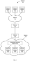
- a network 100 may include networks 110 and 130, which are communicatively coupled via gateways 115 and 125.
- the network 130 includes a hierarchical recursive network (HRN) 140 and endpoint modules 150 connected to the HRN 140.
- HRN hierarchical recursive network
- the network 130 also includes the gateway 125.
- endpoint modules 160 are coupled to network 110 and can communicate with the endpoint modules 150 via the network 110, the gateways (115, 125), and the HRN 140.
- An endpoint module (150, 160) may be an endpoint device (e.g., a server computer, laptop computer, desktop computer, tablet computer, smartphone, etc.) or an application executing on an endpoint device (e.g., a virtual machine). Some embodiments of endpoint devices are described in further detail below.
- Each endpoint module may be assigned at least one unique network identifier ("network ID"), for example, an Internet Protocol (IP) address, a media access control (MAC) address, etc.
- IP Internet Protocol
- MAC media access control
- the network 110 may include one or more communication networks of any suitable type. Some examples of communication networks include a local area network ("LAN”), a wide area network ("WAN”), e.g., the Internet (or a portion thereof), etc. Communication networks may include wired and/or wireless networks.
- the network 110 may perform routing using any suitable routing techniques (e.g., link-state routing, distance vector routing, etc.). In some embodiments, the network 110 routes data packets based on the network IDs of the endpoint modules to which the data packets are addressed. As discussed above, performing routing based on the unique network IDs of the endpoint modules can lead to loss of connectivity when mobile endpoint modules (150, 160) change locations, and can also lead to very large routing tables and associated routing inefficiencies.
- the gateways may route packets between networks (e.g., network 110 and network 130) based on the network IDs of the endpoint modules to which the packets are addressed.
- networks e.g., network 110 and network 130
- the gateway 115 forwards the packet to the network 110 for routing to that endpoint module 160.
- the gateway 115 forwards the packet to (or toward) the gateway 125 for routing to the endpoint module 150 via the hierarchical recursive network 140.
- gateway 125 When gateway 125 receives a packet addressed to the network ID of one of the endpoint modules 150, the gateway 125 forwards the packet to the HRN 140 for routing to that endpoint module 150. When gateway 125 receives a packet addressed to the network ID of one of the endpoint modules 160, the gateway 125 forwards the packet to (or toward) the gateway 115 for routing to the endpoint module 160 via the network 110.
- An example implementation of a gateway is described below with reference to FIGS. 6 and 7 .
- network devices e.g., routers
- a hierarchical topology e.g., a tree
- the network devices may autonomically assign the hierarchical addresses to themselves, and/or the hierarchical addresses may be assigned to the network devices by users (e.g., network administrators).
- the network devices can use recursive routing protocols.
- the routing protocol is implemented using an existing protocol, such as IS-IS.
- core routers e.g., routers that are not directly connected to endpoint devices 150
- edge routers e.g., routers that are directly connected to endpoint devices 150
- core routers can determine how to forward packets within the HRN 140 based on prefixes of the packets' destination addresses
- edge routers e.g., routers that are directly connected to endpoint devices 150
- prefix-based recursive routing can greatly reduce the sizes of the routing tables maintained by the network devices in the HRN 140.
- the edge routers can assign hierarchical addresses to the endpoint modules, and a network registrar can maintain a mapping between the unique network IDs of the endpoint modules and their corresponding hierarchical addresses.
- the network registrar can be centralized or distributed.
- an endpoint module physically moves to a different location in the network, the module can maintain its unique network ID but receive a new hierarchical address from the network.
- connectivity in the network layer can be maintained as endpoint modules move, thereby facilitating increased mobility of the endpoint modules.
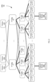
- the network 140 has a hierarchical topology (in particular, a tree topology), with the network devices (e.g., routing devices) organized in three levels.
- the first (lowest) level includes the edge routers ("ER") 210. Each edge router 210 may be connected to many endpoint modules 150, though, in the example of FIG. 2 , only two endpoint modules 150a and 150b are shown.
- the second (intermediate) level includes the core routers ("CR") 220. Each of the core routers 220 in the second level may be connected to one or more edge routers 210 in the first level.
- the third (highest) level includes the core routers ("CR") 230. Each of the core routers 230 in the third level may be connected to one or more core routers 220 in the second level and to one or more gateways 125.
- the network devices are not only organized in a hierarchical topology, but also assigned hierarchical addresses corresponding to their locations within the topology.
- edge router 210c is assigned address 1.1.3
- all the endpoint modules 150 connected to edge router 210c are assigned addresses with a prefix of 1.1.3, matching the address of the edge router 210c.
- core router 220a is assigned address 1.1
- all edge routers 210 assigned addresses with a prefix of 1.1 i.e., ERs 210a, 210b, and 210c
- core router 230a is assigned address 1, and all core routers 220 assigned addresses with a prefix of 1 (i.e., CRs 220a, 220b, and 220c) are connected to CR 230a.
- some of the edge routers 210 in the first level are connected to more than one core router 220 in the second level, and some of the core routers 220 in the second level are connected to more than one core router 230 in the third level.
- These redundant links within the network 140 can facilitate fault tolerance and load balancing. In addition, these redundant links do not interfere with the hierarchical topology of the network 140, nor do they interfere with the network's hierarchical addressing scheme.
- a recursive routing protocol may be characterized by the following conditions:
- the hierarchical address of an endpoint module 150 is maintained by a registrar of the network 140 as a temporary alias.
- the endpoint module 150 registers with the network registrar via the edge router 210 to which the endpoint module 150 is connected, and the registration information (e.g., the endpoint module's temporary alias (hierarchical address) and unique network ID) is distributed to other network devices that provide the same registration service.
- the endpoint module 150a registers with the edge router 210c, which has an address of 1.1.3.
- the registrar assigns the endpoint module 150a a temporary alias (hierarchical address) that complies with the hierarchical addressing scheme, i.e., a hierarchical address that includes the address of the edge router 210c as a prefix.
- the hierarchical address assigned to the endpoint module 150a is 1.1.3.10.
- the endpoint module 150a registers with a single edge router 210c.
- endpoint modules 150 can register with one or more edge routers 210. Redundant registration and connection of the endpoint modules 150 to multiple edge routers can increase the network's resilience, and may also facilitate load balancing.
- the endpoint module may be assigned multiple unique network IDs (one for each registration) and multiple hierarchical addresses (one for each edge router).
- endpoint module 150b has been assigned address N.2.1.76 and is connected to edge router 210p, which has been assigned address N.2.1.
- endpoint module 150b addresses the network layer packet P NL to endpoint module 150a's unique network ID, and forwards the packet to edge router 210p at the network layer.
- Edge router 210p queries the registrar for the location of endpoint module 150a (e.g., the address of the edge router 210 to which the endpoint module 150a is connected).
- Edge router 210p receives a response from the registrar, indicating that endpoint module 150a is connected to the edge router (210c) with address 1.1.3.
- the edge router 210p checks its routing table for entries matching the packet's destination address 1.1.3. In this case, the only route from edge router 210p to any address beginning with the prefix "1" is through the core router 220i. Thus, the packet's destination address "1.1.3" matches an entry "1.x.x” in the edge router's routing table, and the edge router 210p forwards the packet to core router 220i via the port corresponding to the matching table entry.
- the core router 220i checks its routing table for entries matching the packet's destination address 1.1.3.
- address 1.1.3 is reachable via core routers 220a, 220b, and 220c, so the routing table may include an entry "1.1.x” corresponding to core router 220a, an entry "1.x.x” corresponding to core router 1.2, and another entry "1.x.x” corresponding to core router 1.3.
- the core router 220i may use any suitable technique to select among the matching entries (e.g., a routing metric, equal cost multipath selection, etc.). For purposes of this example, the core router 220i selects the table entry "1.1.x" because it matches the longest prefix portion of the destination address 1.1.3, and forwards the packet to core router 220a.
- the core router 220a checks its routing table for entries matching the packet's destination address 1.1.3.
- address 1.1.3 is reachable via edge router 210c and via core router 230a.
- the core router 220i may use any suitable technique to select among the matching entries. For purposes of this example, the core router 220a selects the table entry "1.1.3" because it matches the entire destination address 1.1.3, and forwards the packet to edge router 210c.
- the packet has reached the edge router (210c) to which the endpoint module 150a is connected.
- the edge router 210c checks with the registrar to determine whether a temporal alias (hierarchical address) has already been assigned to the unique network ID of the endpoint module 150a.
- the registrar has assigned temporal alias 1.1.3.10 to the endpoint module 150a.
- the edge router checks its routing table for an entry matching the endpoint module's temporal alias, and forwards the packet to endpoint module 150a using the information in the matching table entry.
- the unique network ID of each endpoint module has only local meaning to the edge router to which the endpoint module is connected.
- any response packet from endpoint module 150a to endpoint module 150b can be returned using the same recursive hop-by-hop routing as the received packet.
- none of the network devices need to have an entry for the full address of the endpoint module, only for the next hop.
- the number of layers in the network 140 is practically unlimited and can be artificially determined based on suitable criteria, thus providing flexibility in network design.
- the network 140 When a new network device or routing layer is added to the network 140, the network autonomically readdresses the network devices, as doing so does not disrupt any connectivity.
- This architecture provides mobility for endpoint modules (e.g., services, hosts, etc.) in the network, as the host connectivity is not bound by network layer addressing and enforces security, as different intents can be enforced at different points in the network without adding any specialized network devices such as firewalls, etc.
- routing devices in the network 140 are in a single routing layer governed by the same routing protocol, even though the routing devices are organized in different levels of a hierarchical topology.
- the different routing devices in the network 140 may be included in different routing layers, which may be governed by different routing protocols.
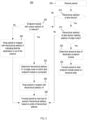
- an edge router 210 may perform a routing method 300 to route packets in a hierarchical recursive network.
- the edge router receives a packet.
- the edge router may receive the packet from an endpoint module 150 connected to the edge router, or from a core router 220 connected to the edge router.
- the edge router may determine whether it received the packet from an endpoint module 150 or from a core router, and may store data indicating which type of device provided the packet to facilitate further processing of the packet.
- the edge router may determine which type of device provided the packet based on which port received the packet (e.g., because the edge router may have access to data indicating which of its ports are connected to endpoint modules and which of its ports are connected to core routers), based on the packet's type (e.g., because endpoint modules generally send network layer packets addressed to unique network IDs, whereas core routers generally send hierarchical recursive routing packets addressed to hierarchical addresses in the network.
- the edge router determines whether the packet includes a hierarchical address of a destination device in the network. In some embodiments, the edge router makes this determination by examining the contents of the packet. For example, the packet's type may indicate whether the packet contains a hierarchical address. In some embodiments, the edge router makes this determination based on which type of device sent the packet. For example, the edge router may determine that packets received from core routers include hierarchical addresses of destination devices, and that packets received from endpoint modules do not include such addresses.
- the edge router determines whether it is the destination device (e.g., by looking up the hierarchical address of the destination device in a routing table and determining that the packet's destination address matches the table entry for the edge router's own address.
- the edge router proceeds to step 320.
- the edge router extracts the unique network ID of the destination endpoint module from the packet and determines the temporal alias (hierarchical address) of the destination endpoint module.
- the edge router assigns the endpoint module's temporal alias, and the edge router adds an entry to its routing table, such that the entry maps the temporal alias of the endpoint module to an edge router port to which the endpoint module is connected.
- the edge router forwards the packet to the endpoint module.
- the edge router may look up the temporal alias of the endpoint module (or the suffix thereof) in the routing table, identify the edge router port connected to the endpoint module based on the data in the matching entry in the routing table, and forward the packet to the endpoint module via the identified port.
- the edge router proceeds to step 330.
- the edge router extracts a unique network ID of the destination device from the packet and determines whether an endpoint module having that network ID is in the network. In some embodiments, the edge router makes this determination by querying the network registrar to determine whether an endpoint module having that network ID has registered on the network.
- the edge router proceeds to step 350.
- the edge router prepares to route the packet outside the hierarchical network. For example, the edge router may wrap the packet in a wrapper with a special hierarchical address ("X") indicating that destination endpoint module is outside the network.
- the edge router forwards the packet to the next hop for the packet's destination address, based on a prefix of the destination address. In the scenario in which the destination address is the special hierarchical address X, the edge router forwards the packet to a core router in the second routing level, and the core routers recursively forward the packet to a gateway 125 for routing outside the network.
- the edge router may use a routing table to identify one or more potential next hops along the packet's route, and may use any suitable criteria to select the next hop if the routing table identifies multiple potential next hops.
- the edge router proceeds to step 335.
- the edge router has received the packet from an endpoint module connected to the edge router, and in steps 335, 340, and 360, the edge router prepares the packet for routing through the hierarchical recursive network 140 and forwards the packet to the next hop on its route toward the destination endpoint module.
- the edge router determines the hierarchical address of the edge router to which the destination endpoint module is connected. In some embodiments, the edge router makes this determination by querying the network registrar for the address of the edge router with which the destination endpoint module is registered. At step 340, the edge router wraps the packet in a wrapper with the address of the edge router to which the destination endpoint module is connected. At step 360, the edge router forwards the packet to the next hop for the packet's destination address, based on a prefix of the destination address.
- the source edge router forwards the packet to a core router in the second routing level, and the core routers recursively forward the packet to the destination edge router.
- the edge router may use a routing table to identify one or more potential next hops along the packet's route, and may use any suitable criteria to select the next hop if the routing table identifies multiple potential next hops.
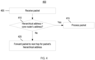
- a core router (220, 230) may perform a routing method 400 to route packets in a hierarchical recursive network.
- the core router receives a packet.
- the core router may receive the packet from a gateway 125 connected to the network, from another core router, or from an edge router.
- the core router may determine whether it received the packet from (1) a gateway, or (2) a core router or edge router.
- the core router simply proceeds to step 410.
- the core router may extract the unique network ID of the destination endpoint module from the packet and query the network registrar to determine whether the unique network ID is registered on the network, and if so, to identify the hierarchical address of the edge router to which the destination endpoint module is connected.
- the core router may then wrap the packet in a wrapper having its destination address set to the hierarchical address of that edge router.
- the core router then proceeds to step 410.
- the core router determines whether destination address of the packet is the core router's address. If so, the core router processes the packet at step 415. Otherwise, the core router proceeds to step 420.
- the core router forwards the packet to the next hop on its route to the destination endpoint module based on the packet's hierarchical address. As described above, the core router may use a routing table to identify one or more potential next hops along the packet's route, and may use any suitable criteria to select the next hop if the routing table identifies multiple potential next hops.
- the hierarchical recursive network 140 can be used to perform packet routing in a datacenter.
- the edge routers 210 can be top-of-rack switches (TORs)
- the core routers 220 can be fabric switches
- the core routers 230 can be spines.
- the endpoint modules 150 can be servers or applications executing on servers (e.g., virtual machines).
- FIG. 5 further illustrates how logical network constructs that may be beneficial in the datacenter environment can be implemented using the hierarchical recursive network 140 of FIG. 2 .
- the vertical structures in dashed lines represent routing devices.
- the edge router 210c is implemented using a TOR (which is connected to the endpoint module 150a)
- the core router 220a connected to the edge router 210c is implemented using a fabric switch
- the core router 230a connected to the core router 220a is implemented using a spine
- the core router 210i connected to the core router 230a is implemented using another fabric switch
- the edge router 210p connected to the core router 210i is implemented using another TOR (which is connected to the endpoint module 150b).
- the horizontal structures 510-540 represent logical network constructs that may facilitate communication in the datacenter.
- the network constructs include multiple service / tenant inter-process communication (IPC) fabrics 510 (e.g., one service / tenant IPC fabric per service / tenant of the datacenter), an inter-datacenter IPC fabric 520 (connecting two or more datacenters), an intra-datacenter IPC fabric 530 (e.g., one intra-datacenter IPC fabric per physical datacenter), and multiple shim IPC data fabrics 540 (e.g., reduced broadcast domains within a physical datacenter).
- IPC inter-process communication
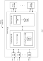
- a network system 600 is shown.
- the gateways (115, 125), edge routers 210, and/or core routers (220, 230) of FIGS. 1 and 2 may be implemented, using embodiments of the network system 600.
- the network system 600 provides a forwarding plane 612, a routing component (routing plane 616), and a servicing component (service plane 614) to provide for packet servicing and forwarding by the network system.
- Network system 600 may be a high-end router capable of deployment within a service provider network or datacenter.
- forwarding plane 612 may be provided by dedicated forwarding integrated circuits, may be distributed (e.g., over a multi-stage switch fabric, such a 3-stage Clos switch fabric, or over a multi-chassis router), and may accommodate processing related to pure routing as well as other network services (e.g., firewall and deep packet inspection processing).
- routing plane 616 and forwarding plane 612 may operate as a high-end router.
- the network system 600 is distributed, such that two or more of the forwarding plane 612, servicing plane 614, and routing plane 616 are implemented on using different devices, rather than being integrated in the same device.
- each edge router 210 and core router (220, 230) may implement a forwarding plane 612, and the servicing plane and routing plane may be located remotely from the forwarding plane.
- a network system 600 may include one or more routing planes 612 (or routing engines 628) per forwarding plane 612 (or forwarding component 630). Separating the planes in this manner may reduce the computational burden on the edge and core routers, thereby enhancing the speed and efficiency of the network.
- the servicing plane 614 may be tightly integrated within the network device (e.g., by way of service cards) so as to use forwarding plane 612 of the routing components in a shared, cooperative manner.
- the servicing plane may perform security operations on packets sent to the service plane 614 by the flow control unit 620. For example, when a packet of an incoming packet flow is received by network device 600 (e.g., via an interface card 794 of the network device 600) and injected into the forwarding plane 612 normally used for packet routing, the flow control unit 620 of forwarding plane 612 may analyzes the packet and determine based on the analysis whether to (1) send the packet through one or more service cards 624 of the service plane 614 or (2) send the packet directly to the forwarding component 630.
- Service cards 624 within security plane 614 may be installed along a backplane or other interconnect of network device 600 to perform a variety of types of processing to packets, such as Intrusion Detection and Prevention (IDP) analysis, virus scanning, deep packet inspection, or ciphering.
- service cards 624 may provide application layer gateway (ALG) and protocol proxy software applications, e.g., for Voice over IP (VoIP) call setup.
- ALG application layer gateway
- VoIP Voice over IP
- a service card 624 may issue commands for dynamic installation of filters into a flow table / removal of filters from the flow table (not shown) within flow control unit 620 of forwarding plane 612.
- forwarding component 630 may apply an appropriate action according to a dynamic filter that matched the packet.
- Exemplary actions that network device 600 may apply in forwarding plane 612 as specified by filters include rate limiting, queuing, routing, firewalling (i.e., blocking or dropping the packet), counting, network address translation (NAT), quality of service (QoS), sequence number adjustment, or other types of actions.
- actions typically performed by a security device and actions typically performed by a router can be combined in an integrated manner within the shared forwarding plane 612 to streamline packet forwarding in network device 600.
- the service plane 614 may not be included in the network device 600.
- Network device 600 includes a routing engine 628 that provides a routing plane 616 and a downstream forwarding component 630 within forwarding plane 612.
- Routing engine 628 is primarily responsible for maintaining a routing information base (RIB) 632 to reflect the current topology of the network (e.g., network 140) and other network entities to which network device 600 is connected.
- RIB routing information base
- routing engine 628 may provide an operating environment for execution of routing protocols that communicate with peer routers and periodically update RIB 632 to accurately reflect the topology of the network and the other network entities.
- forwarding component 630 maintains forwarding information base (FIB) 634 that associates network destinations (e.g., hierarchical network addresses or prefixes thereof) with specific next hops and corresponding interface ports of output interface cards of network device 600.
- Routing engine 628 may process RIB 632 to perform route selection and generate FIB 634 based on selected routes.
- forwarding component 630 traverses the routing table of the network device 600 based on information (e.g., a hierarchical network address of a destination endpoint module, or a prefix thereof) within a header of the packet to ultimately select a next hop and output interface to which to forward the packet.
- the network device 600 may include a control unit 782 that includes a routing engine 628 and a forwarding engine 786.
- the routing engine 628 is primarily responsible for maintaining routing information base (RIB) 632.
- Routing engine 628 also includes routing protocols 789 that perform routing operations.
- forwarding component 630 of forwarding engine 786 maintains forwarding information base (FIB) 634 that associates network destinations (e.g., hierarchical network addresses or prefixes thereof) with specific next hops and corresponding interface ports.
- FIB forwarding information base
- Network device 600 includes interface cards 794a-794n (“IFCs 794") that receive and send packets via network links. IFCs 794 may be coupled to the network links via a number of interface ports. Generally, flow control unit 620 of forwarding engine 786 may relay certain packets received from IFCs 794 to service cards 624a-624m ("service cards 624") in accordance with filter settings. Service cards 100 may receive packets from flow control unit 620, selectively provide services in accordance with information within the packet, and relay the packet or any response packets to control unit 782 for forwarding by forwarding component 630.
- IFCs 794 may be coupled to the network links via a number of interface ports.
- flow control unit 620 of forwarding engine 786 may relay certain packets received from IFCs 794 to service cards 624a-624m ("service cards 624") in accordance with filter settings.
- Service cards 100 may receive packets from flow control unit 620, selectively provide services in accordance with information within the packet, and relay the packet or any response packet
- each of forwarding engine 786 and routing engine 628 may include one or more dedicated data processing apparatus and may be communicatively coupled by a data communication channel.
- the data communication channel may be a high-speed network connection, bus, shared-memory or other data communication mechanism.
- Forwarding engine 786, routing engine 628, or both, may make use of the data structures and organization described above with respect to FIG. 6 .
- routing plane 616 of FIG. 6 may correspond to routing engine 628
- forwarding plane 612 of FIG. 6 may correspond to forwarding engine 786
- interface cards 794 and service plane 14 of FIG. 1 may correspond to service cards 624.
- Network device 600 may further include a chassis (not shown) for housing control unit 782.
- the chassis has a number of slots (not shown) for receiving a set of cards, including IFCs 794 and service cards 624. Each card may be inserted into a corresponding slot of the chassis for electrically coupling the card to control unit 782 via a bus, backplane, or other electrical communication mechanism.
- Service cards 624 may relay processed packets or reply packets to control unit 782.
- Control unit 782 may forwards the packet in accordance with FIB 634.
- the forwarding component 630 may apply one or more actions to packets relayed to the forwarding component 630 by control unit 782, as specified by matching filters. For example, forwarding component 630 may perform rate limiting, queuing, packet mirroring, routing, firewalling (i.e., blocking or dropping the packet), counting, logging, network address translation (NAT), sequence number adjustment, quality of service (QoS), or other types of actions.
- the functions of network device 600 may be implemented by executing, with one or more data processing apparatus, instructions fetched from a computer-readable storage medium.
- data processing apparatus encompasses all kinds of apparatus, devices, and machines for processing data, including by way of example a programmable processor (e.g., a general or special purpose microprocessor), a system on a chip, or multiple ones or combinations, of the foregoing.
- the apparatus can include special purpose logic circuitry, e.g., an FPGA (field programmable gate array) or an ASIC (application specific integrated circuit).
- a processor will receive instructions and data a computer-readable storage medium. Examples of such media include random access memory (RAM), read-only memory (ROM), non-volatile random access memory (NVRAM), electrically erasable programmable read-only memory (EEPROM), flash memory, and the like.
- An endpoint device may include a computer, which may include one or more data processing apparatus for performing actions in accordance with instructions and one or more memory devices for storing instructions and data.
- a computer will also include, or be operatively coupled to receive data from or transfer data to, or both, one or more mass storage devices for storing data, e.g., magnetic, magneto-optical disks, or optical disks.
- mass storage devices for storing data, e.g., magnetic, magneto-optical disks, or optical disks.
- a computer need not have such devices.
- a computer can be embedded in an endpoint device, e.g., a mobile telephone, a personal digital assistant (PDA), a mobile audio or video player, a game console, a Global Positioning System (GPS) receiver, or a portable storage device (e.g., a universal serial bus (USB) flash drive), to name just a few.
- Endpoint device e.g., a mobile telephone, a personal digital assistant (PDA), a mobile audio or video player, a game console, a Global Positioning System (GPS) receiver, or a portable storage device (e.g., a universal serial bus (USB) flash drive), to name just a few.
- Devices suitable for storing computer program instructions and data include all forms of non-volatile memory, media and memory devices, including by way of example semiconductor memory devices, e.g., EPROM, EEPROM, and flash memory devices; magnetic disks, e.g., internal hard disks or removable disks; magneto-optical disks; and CD
- the techniques described herein can be implemented in digital electronic circuitry, or in computer hardware, firmware, software, or in combinations of them.
- the techniques can be implemented as a computer program product, i.e., a computer program tangibly embodied in an information carrier, e.g., in a machine-readable storage device or other non-transitory storage medium, for execution by, or to control the operation of, data processing apparatus, e.g., a programmable processor, a computer, or multiple computers.
- a computer program can be written in any form of programming language, including compiled or interpreted languages, and it can be deployed in any form, including as a stand-alone program or as a module, component, subroutine, or other unit suitable for use in a computing environment.
- a computer program can be deployed to be executed on one computer or on multiple computers at one site or distributed across multiple sites and interconnected by a communication network.
- a reference to "A and/or B", when used in conjunction with open- ended language such as “comprising” can refer, in one embodiment, to A only (optionally including elements other than B); in another embodiment, to B only (optionally including elements other than A); in yet another embodiment, to both A and B (optionally including other elements); etc.
- the phrase "at least one,” in reference to a list of one or more elements, should be understood to mean at least one element selected from any one or more of the elements in the list of elements, but not necessarily including at least one of each and every element specifically listed within the list of elements and not excluding any combinations of elements in the list of elements.
- This definition also allows that elements may optionally be present other than the elements specifically identified within the list of elements to which the phrase "at least one" refers, whether related or unrelated to those elements specifically identified.
- At least one of A and B can refer, in one embodiment, to at least one, optionally including more than one, A, with no B present (and optionally including elements other than B); in another embodiment, to at least one, optionally including more than one, B, with no A present (and optionally including elements other than A); in yet another embodiment, to at least one, optionally including more than one, A, and at least one, optionally including more than one, B (and optionally including other elements); etc.
Landscapes
- Engineering & Computer Science (AREA)
- Computer Networks & Wireless Communication (AREA)
- Signal Processing (AREA)
- Computer Security & Cryptography (AREA)
- Data Exchanges In Wide-Area Networks (AREA)
Applications Claiming Priority (3)
| Application Number | Priority Date | Filing Date | Title |
|---|---|---|---|
| US201562259934P | 2015-11-25 | 2015-11-25 | |
| EP16820043.4A EP3381162B1 (en) | 2015-11-25 | 2016-11-25 | Network routing systems and techniques |
| PCT/US2016/063788 WO2017091820A1 (en) | 2015-11-25 | 2016-11-25 | Network routing systems and techniques |
Related Parent Applications (1)
| Application Number | Title | Priority Date | Filing Date |
|---|---|---|---|
| EP16820043.4A Division EP3381162B1 (en) | 2015-11-25 | 2016-11-25 | Network routing systems and techniques |
Publications (2)
| Publication Number | Publication Date |
|---|---|
| EP3930269A1 EP3930269A1 (en) | 2021-12-29 |
| EP3930269B1 true EP3930269B1 (en) | 2024-10-23 |
Family
ID=57681723
Family Applications (2)
| Application Number | Title | Priority Date | Filing Date |
|---|---|---|---|
| EP21167816.4A Active EP3930269B1 (en) | 2015-11-25 | 2016-11-25 | Network routing systems and techniques |
| EP16820043.4A Active EP3381162B1 (en) | 2015-11-25 | 2016-11-25 | Network routing systems and techniques |
Family Applications After (1)
| Application Number | Title | Priority Date | Filing Date |
|---|---|---|---|
| EP16820043.4A Active EP3381162B1 (en) | 2015-11-25 | 2016-11-25 | Network routing systems and techniques |
Country Status (4)
| Country | Link |
|---|---|
| US (2) | US10237180B2 (enExample) |
| EP (2) | EP3930269B1 (enExample) |
| JP (2) | JP6839859B2 (enExample) |
| WO (1) | WO2017091820A1 (enExample) |
Families Citing this family (4)
| Publication number | Priority date | Publication date | Assignee | Title |
|---|---|---|---|---|
| US11418460B2 (en) * | 2017-05-15 | 2022-08-16 | Consensii Llc | Flow-zone switching |
| FR3076142A1 (fr) * | 2017-12-21 | 2019-06-28 | Bull Sas | Procede et serveur d'attribution d'adresses topologiques a des commutateurs de reseau, programme d'ordinateur et grappe de serveurs correspondants |
| US11025526B2 (en) * | 2020-11-18 | 2021-06-01 | Paul Oren Rabinowitz | Control of event-driven software applications |
| US11334475B1 (en) * | 2020-11-18 | 2022-05-17 | Paul Oren Rabinowitz | Graph based event-driven computing |
Family Cites Families (23)
| Publication number | Priority date | Publication date | Assignee | Title |
|---|---|---|---|---|
| US5351146A (en) * | 1993-03-01 | 1994-09-27 | At&T Bell Laboratories | All-optical network architecture |
| US5831975A (en) * | 1996-04-04 | 1998-11-03 | Lucent Technologies Inc. | System and method for hierarchical multicast routing in ATM networks |
| US6070187A (en) * | 1998-03-26 | 2000-05-30 | Hewlett-Packard Company | Method and apparatus for configuring a network node to be its own gateway |
| US6247058B1 (en) * | 1998-03-30 | 2001-06-12 | Hewlett-Packard Company | Method and apparatus for processing network packets using time stamps |
| US20010032271A1 (en) * | 2000-03-23 | 2001-10-18 | Nortel Networks Limited | Method, device and software for ensuring path diversity across a communications network |
| US20040073659A1 (en) * | 2002-10-15 | 2004-04-15 | Carl Rajsic | Method and apparatus for managing nodes in a network |
| US8014321B2 (en) | 2004-10-22 | 2011-09-06 | Microsoft Corporation | Rendezvousing resource requests with corresponding resources |
| US8135362B2 (en) * | 2005-03-07 | 2012-03-13 | Symstream Technology Holdings Pty Ltd | Symbol stream virtual radio organism method and apparatus |
| US8107448B2 (en) * | 2005-10-14 | 2012-01-31 | Panasonic Corporation | Apparatus for reducing signalling data bursts in mobile network |
| US7519734B1 (en) * | 2006-03-14 | 2009-04-14 | Amazon Technologies, Inc. | System and method for routing service requests |
| US8040850B2 (en) * | 2006-08-21 | 2011-10-18 | Qualcomm Incorporated | Advanced internet protocol with flash-OFDM methods and systems |
| JP5004683B2 (ja) * | 2007-06-08 | 2012-08-22 | 三菱電機株式会社 | 無線通信端末 |
| US8325706B2 (en) * | 2007-11-26 | 2012-12-04 | Verizon Patent And Licensing Inc. | Hierarchical segmented label switched paths |
| US8339959B1 (en) | 2008-05-20 | 2012-12-25 | Juniper Networks, Inc. | Streamlined packet forwarding using dynamic filters for routing and security in a shared forwarding plane |
| ES2361545B1 (es) * | 2009-02-24 | 2012-05-08 | Universidad De Alcala De Henares | Procedimiento de encaminamiento de tramas de datos y puente de red. |
| US8331370B2 (en) * | 2009-12-17 | 2012-12-11 | Amazon Technologies, Inc. | Distributed routing architecture |
| US10110553B2 (en) * | 2012-10-11 | 2018-10-23 | Cable Television Laboratories, Inc. | Adaptive prefix delegation |
| US9634866B2 (en) * | 2013-09-06 | 2017-04-25 | Intel Corporation | Architecture and method for hybrid circuit-switched and packet-switched router |
| US9313129B2 (en) * | 2014-03-14 | 2016-04-12 | Nicira, Inc. | Logical router processing by network controller |
| US9590901B2 (en) * | 2014-03-14 | 2017-03-07 | Nicira, Inc. | Route advertisement by managed gateways |
| US9490419B2 (en) * | 2014-07-21 | 2016-11-08 | Cisco Technology, Inc. | DHCPv6 address autoconfiguration for source-routed networks |
| US10057157B2 (en) * | 2015-08-31 | 2018-08-21 | Nicira, Inc. | Automatically advertising NAT routes between logical routers |
| US10841208B2 (en) * | 2016-08-05 | 2020-11-17 | Huawei Technologies Co., Ltd. | Slice/service-based routing in virtual networks |
-
2016
- 2016-11-25 US US15/361,333 patent/US10237180B2/en active Active
- 2016-11-25 EP EP21167816.4A patent/EP3930269B1/en active Active
- 2016-11-25 EP EP16820043.4A patent/EP3381162B1/en active Active
- 2016-11-25 JP JP2018527975A patent/JP6839859B2/ja active Active
- 2016-11-25 WO PCT/US2016/063788 patent/WO2017091820A1/en not_active Ceased
-
2019
- 2019-03-04 US US16/291,440 patent/US20200036633A1/en not_active Abandoned
-
2021
- 2021-02-01 JP JP2021014383A patent/JP2021090203A/ja active Pending
Also Published As
| Publication number | Publication date |
|---|---|
| EP3381162A1 (en) | 2018-10-03 |
| JP6839859B2 (ja) | 2021-03-10 |
| JP2021090203A (ja) | 2021-06-10 |
| US10237180B2 (en) | 2019-03-19 |
| EP3381162B1 (en) | 2021-04-14 |
| US20200036633A1 (en) | 2020-01-30 |
| JP2018535619A (ja) | 2018-11-29 |
| EP3930269A1 (en) | 2021-12-29 |
| US20170171072A1 (en) | 2017-06-15 |
| WO2017091820A1 (en) | 2017-06-01 |
Similar Documents
| Publication | Publication Date | Title |
|---|---|---|
| US11212215B2 (en) | Routing optimizations in a network computing environment | |
| EP3254417B1 (en) | Method and system for supporting port ranging in a software-defined networking (sdn) system | |
| US9985883B2 (en) | Name-based routing system and method | |
| US8675656B2 (en) | Scaling virtual private networks using service insertion architecture | |
| US8675543B2 (en) | Route limiting in border gateway protocol over satellite networks | |
| US10116556B2 (en) | Techniques for routing and forwarding between multiple virtual routers implemented by a single device | |
| US11663052B2 (en) | Adaptive application assignment to distributed cloud resources | |
| US9973435B2 (en) | Loopback-free adaptive routing | |
| US11294730B2 (en) | Process placement in a cloud environment based on automatically optimized placement policies and process execution profiles | |
| EP3879757B1 (en) | Network traffic steering among cpu cores using forwarding path elements | |
| US12317179B2 (en) | Dynamic access network selection based on application orchestration information in an edge cloud system | |
| JP2021090203A (ja) | ネットワークルーティングシステムおよび技法 | |
| CN108259205A (zh) | 一种路由发布方法及网络设备 | |
| WO2020100150A1 (en) | Routing protocol blobs for efficient route computations and route downloads | |
| WO2019097281A1 (en) | Adaptive hash function using bit position scoring to select fragmented windows | |
| JP2018082317A (ja) | ルーティングシステムおよびルーティング方法 | |
| CN115914100A (zh) | Rt4路由报文r4的发布方法及装置、存储介质及电子装置 |
Legal Events
| Date | Code | Title | Description |
|---|---|---|---|
| PUAI | Public reference made under article 153(3) epc to a published international application that has entered the european phase |
Free format text: ORIGINAL CODE: 0009012 |
|
| STAA | Information on the status of an ep patent application or granted ep patent |
Free format text: STATUS: THE APPLICATION HAS BEEN PUBLISHED |
|
| AC | Divisional application: reference to earlier application |
Ref document number: 3381162 Country of ref document: EP Kind code of ref document: P |
|
| AK | Designated contracting states |
Kind code of ref document: A1 Designated state(s): AL AT BE BG CH CY CZ DE DK EE ES FI FR GB GR HR HU IE IS IT LI LT LU LV MC MK MT NL NO PL PT RO RS SE SI SK SM TR |
|
| B565 | Issuance of search results under rule 164(2) epc |
Effective date: 20211125 |
|
| STAA | Information on the status of an ep patent application or granted ep patent |
Free format text: STATUS: REQUEST FOR EXAMINATION WAS MADE |
|
| 17P | Request for examination filed |
Effective date: 20220609 |
|
| RBV | Designated contracting states (corrected) |
Designated state(s): AL AT BE BG CH CY CZ DE DK EE ES FI FR GB GR HR HU IE IS IT LI LT LU LV MC MK MT NL NO PL PT RO RS SE SI SK SM TR |
|
| REG | Reference to a national code |
Ref legal event code: R079 Ipc: H04L0045020000 Ref country code: DE Ref legal event code: R079 Ref document number: 602016089996 Country of ref document: DE Free format text: PREVIOUS MAIN CLASS: H04L0012721000 Ipc: H04L0045020000 |
|
| GRAP | Despatch of communication of intention to grant a patent |
Free format text: ORIGINAL CODE: EPIDOSNIGR1 |
|
| STAA | Information on the status of an ep patent application or granted ep patent |
Free format text: STATUS: GRANT OF PATENT IS INTENDED |
|
| RIC1 | Information provided on ipc code assigned before grant |
Ipc: H04L 45/02 20220101AFI20240611BHEP |
|
| INTG | Intention to grant announced |
Effective date: 20240709 |
|
| GRAS | Grant fee paid |
Free format text: ORIGINAL CODE: EPIDOSNIGR3 |
|
| GRAA | (expected) grant |
Free format text: ORIGINAL CODE: 0009210 |
|
| STAA | Information on the status of an ep patent application or granted ep patent |
Free format text: STATUS: THE PATENT HAS BEEN GRANTED |
|
| AC | Divisional application: reference to earlier application |
Ref document number: 3381162 Country of ref document: EP Kind code of ref document: P |
|
| AK | Designated contracting states |
Kind code of ref document: B1 Designated state(s): AL AT BE BG CH CY CZ DE DK EE ES FI FR GB GR HR HU IE IS IT LI LT LU LV MC MK MT NL NO PL PT RO RS SE SI SK SM TR |
|
| REG | Reference to a national code |
Ref country code: GB Ref legal event code: FG4D |
|
| REG | Reference to a national code |
Ref country code: CH Ref legal event code: EP |
|
| REG | Reference to a national code |
Ref country code: DE Ref legal event code: R096 Ref document number: 602016089996 Country of ref document: DE |
|
| REG | Reference to a national code |
Ref country code: IE Ref legal event code: FG4D |
|
| P01 | Opt-out of the competence of the unified patent court (upc) registered |
Free format text: CASE NUMBER: APP_60960/2024 Effective date: 20241113 |
|
| PGFP | Annual fee paid to national office [announced via postgrant information from national office to epo] |
Ref country code: DE Payment date: 20241216 Year of fee payment: 9 |
|
| PGFP | Annual fee paid to national office [announced via postgrant information from national office to epo] |
Ref country code: GB Payment date: 20241122 Year of fee payment: 9 |
|
| PGFP | Annual fee paid to national office [announced via postgrant information from national office to epo] |
Ref country code: FR Payment date: 20241108 Year of fee payment: 9 |
|
| REG | Reference to a national code |
Ref country code: LT Ref legal event code: MG9D |
|
| REG | Reference to a national code |
Ref country code: NL Ref legal event code: MP Effective date: 20241023 |
|
| REG | Reference to a national code |
Ref country code: AT Ref legal event code: MK05 Ref document number: 1735769 Country of ref document: AT Kind code of ref document: T Effective date: 20241023 |
|
| PG25 | Lapsed in a contracting state [announced via postgrant information from national office to epo] |
Ref country code: NL Free format text: LAPSE BECAUSE OF FAILURE TO SUBMIT A TRANSLATION OF THE DESCRIPTION OR TO PAY THE FEE WITHIN THE PRESCRIBED TIME-LIMIT Effective date: 20241023 |
|
| PG25 | Lapsed in a contracting state [announced via postgrant information from national office to epo] |
Ref country code: NL Free format text: LAPSE BECAUSE OF FAILURE TO SUBMIT A TRANSLATION OF THE DESCRIPTION OR TO PAY THE FEE WITHIN THE PRESCRIBED TIME-LIMIT Effective date: 20241023 |
|
| PG25 | Lapsed in a contracting state [announced via postgrant information from national office to epo] |
Ref country code: PT Free format text: LAPSE BECAUSE OF FAILURE TO SUBMIT A TRANSLATION OF THE DESCRIPTION OR TO PAY THE FEE WITHIN THE PRESCRIBED TIME-LIMIT Effective date: 20250224 Ref country code: IS Free format text: LAPSE BECAUSE OF FAILURE TO SUBMIT A TRANSLATION OF THE DESCRIPTION OR TO PAY THE FEE WITHIN THE PRESCRIBED TIME-LIMIT Effective date: 20250223 Ref country code: HR Free format text: LAPSE BECAUSE OF FAILURE TO SUBMIT A TRANSLATION OF THE DESCRIPTION OR TO PAY THE FEE WITHIN THE PRESCRIBED TIME-LIMIT Effective date: 20241023 |
|
| PG25 | Lapsed in a contracting state [announced via postgrant information from national office to epo] |
Ref country code: FI Free format text: LAPSE BECAUSE OF FAILURE TO SUBMIT A TRANSLATION OF THE DESCRIPTION OR TO PAY THE FEE WITHIN THE PRESCRIBED TIME-LIMIT Effective date: 20241023 |
|
| PG25 | Lapsed in a contracting state [announced via postgrant information from national office to epo] |
Ref country code: BG Free format text: LAPSE BECAUSE OF FAILURE TO SUBMIT A TRANSLATION OF THE DESCRIPTION OR TO PAY THE FEE WITHIN THE PRESCRIBED TIME-LIMIT Effective date: 20241023 |
|
| PG25 | Lapsed in a contracting state [announced via postgrant information from national office to epo] |
Ref country code: ES Free format text: LAPSE BECAUSE OF FAILURE TO SUBMIT A TRANSLATION OF THE DESCRIPTION OR TO PAY THE FEE WITHIN THE PRESCRIBED TIME-LIMIT Effective date: 20241023 |
|
| PG25 | Lapsed in a contracting state [announced via postgrant information from national office to epo] |
Ref country code: NO Free format text: LAPSE BECAUSE OF FAILURE TO SUBMIT A TRANSLATION OF THE DESCRIPTION OR TO PAY THE FEE WITHIN THE PRESCRIBED TIME-LIMIT Effective date: 20250123 |
|
| PG25 | Lapsed in a contracting state [announced via postgrant information from national office to epo] |
Ref country code: LV Free format text: LAPSE BECAUSE OF FAILURE TO SUBMIT A TRANSLATION OF THE DESCRIPTION OR TO PAY THE FEE WITHIN THE PRESCRIBED TIME-LIMIT Effective date: 20241023 Ref country code: AT Free format text: LAPSE BECAUSE OF FAILURE TO SUBMIT A TRANSLATION OF THE DESCRIPTION OR TO PAY THE FEE WITHIN THE PRESCRIBED TIME-LIMIT Effective date: 20241023 Ref country code: GR Free format text: LAPSE BECAUSE OF FAILURE TO SUBMIT A TRANSLATION OF THE DESCRIPTION OR TO PAY THE FEE WITHIN THE PRESCRIBED TIME-LIMIT Effective date: 20250124 |
|
| PG25 | Lapsed in a contracting state [announced via postgrant information from national office to epo] |
Ref country code: PL Free format text: LAPSE BECAUSE OF FAILURE TO SUBMIT A TRANSLATION OF THE DESCRIPTION OR TO PAY THE FEE WITHIN THE PRESCRIBED TIME-LIMIT Effective date: 20241023 |
|
| PG25 | Lapsed in a contracting state [announced via postgrant information from national office to epo] |
Ref country code: RS Free format text: LAPSE BECAUSE OF FAILURE TO SUBMIT A TRANSLATION OF THE DESCRIPTION OR TO PAY THE FEE WITHIN THE PRESCRIBED TIME-LIMIT Effective date: 20250123 |
|
| REG | Reference to a national code |
Ref country code: CH Ref legal event code: PL |
|
| PG25 | Lapsed in a contracting state [announced via postgrant information from national office to epo] |
Ref country code: SM Free format text: LAPSE BECAUSE OF FAILURE TO SUBMIT A TRANSLATION OF THE DESCRIPTION OR TO PAY THE FEE WITHIN THE PRESCRIBED TIME-LIMIT Effective date: 20241023 |
|
| PG25 | Lapsed in a contracting state [announced via postgrant information from national office to epo] |
Ref country code: MC Free format text: LAPSE BECAUSE OF FAILURE TO SUBMIT A TRANSLATION OF THE DESCRIPTION OR TO PAY THE FEE WITHIN THE PRESCRIBED TIME-LIMIT Effective date: 20241023 |
|
| PG25 | Lapsed in a contracting state [announced via postgrant information from national office to epo] |
Ref country code: DK Free format text: LAPSE BECAUSE OF FAILURE TO SUBMIT A TRANSLATION OF THE DESCRIPTION OR TO PAY THE FEE WITHIN THE PRESCRIBED TIME-LIMIT Effective date: 20241023 |
|
| PG25 | Lapsed in a contracting state [announced via postgrant information from national office to epo] |
Ref country code: LU Free format text: LAPSE BECAUSE OF NON-PAYMENT OF DUE FEES Effective date: 20241125 |
|
| REG | Reference to a national code |
Ref country code: CH Ref legal event code: PL |
|
| PG25 | Lapsed in a contracting state [announced via postgrant information from national office to epo] |
Ref country code: EE Free format text: LAPSE BECAUSE OF FAILURE TO SUBMIT A TRANSLATION OF THE DESCRIPTION OR TO PAY THE FEE WITHIN THE PRESCRIBED TIME-LIMIT Effective date: 20241023 |
|
| PG25 | Lapsed in a contracting state [announced via postgrant information from national office to epo] |
Ref country code: CH Free format text: LAPSE BECAUSE OF NON-PAYMENT OF DUE FEES Effective date: 20241130 |
|
| PG25 | Lapsed in a contracting state [announced via postgrant information from national office to epo] |
Ref country code: RO Free format text: LAPSE BECAUSE OF FAILURE TO SUBMIT A TRANSLATION OF THE DESCRIPTION OR TO PAY THE FEE WITHIN THE PRESCRIBED TIME-LIMIT Effective date: 20241023 |
|
| REG | Reference to a national code |
Ref country code: DE Ref legal event code: R097 Ref document number: 602016089996 Country of ref document: DE |
|
| PG25 | Lapsed in a contracting state [announced via postgrant information from national office to epo] |
Ref country code: SK Free format text: LAPSE BECAUSE OF FAILURE TO SUBMIT A TRANSLATION OF THE DESCRIPTION OR TO PAY THE FEE WITHIN THE PRESCRIBED TIME-LIMIT Effective date: 20241023 |
|
| PG25 | Lapsed in a contracting state [announced via postgrant information from national office to epo] |
Ref country code: CZ Free format text: LAPSE BECAUSE OF FAILURE TO SUBMIT A TRANSLATION OF THE DESCRIPTION OR TO PAY THE FEE WITHIN THE PRESCRIBED TIME-LIMIT Effective date: 20241023 |
|
| PG25 | Lapsed in a contracting state [announced via postgrant information from national office to epo] |
Ref country code: IT Free format text: LAPSE BECAUSE OF FAILURE TO SUBMIT A TRANSLATION OF THE DESCRIPTION OR TO PAY THE FEE WITHIN THE PRESCRIBED TIME-LIMIT Effective date: 20241023 |
|
| REG | Reference to a national code |
Ref country code: BE Ref legal event code: MM Effective date: 20241130 |
|
| PLBE | No opposition filed within time limit |
Free format text: ORIGINAL CODE: 0009261 |
|
| STAA | Information on the status of an ep patent application or granted ep patent |
Free format text: STATUS: NO OPPOSITION FILED WITHIN TIME LIMIT |
|
| PG25 | Lapsed in a contracting state [announced via postgrant information from national office to epo] |
Ref country code: SE Free format text: LAPSE BECAUSE OF FAILURE TO SUBMIT A TRANSLATION OF THE DESCRIPTION OR TO PAY THE FEE WITHIN THE PRESCRIBED TIME-LIMIT Effective date: 20241023 |
|
| 26N | No opposition filed |
Effective date: 20250724 |
|
| PG25 | Lapsed in a contracting state [announced via postgrant information from national office to epo] |
Ref country code: BE Free format text: LAPSE BECAUSE OF NON-PAYMENT OF DUE FEES Effective date: 20241130 |
|
| PG25 | Lapsed in a contracting state [announced via postgrant information from national office to epo] |
Ref country code: IE Free format text: LAPSE BECAUSE OF NON-PAYMENT OF DUE FEES Effective date: 20241125 |