EP3930117A1 - Rotary connector device - Google Patents
Rotary connector device Download PDFInfo
- Publication number
- EP3930117A1 EP3930117A1 EP20758822.9A EP20758822A EP3930117A1 EP 3930117 A1 EP3930117 A1 EP 3930117A1 EP 20758822 A EP20758822 A EP 20758822A EP 3930117 A1 EP3930117 A1 EP 3930117A1
- Authority
- EP
- European Patent Office
- Prior art keywords
- connector
- holder
- wall
- rotary
- connector device
- Prior art date
- Legal status (The legal status is an assumption and is not a legal conclusion. Google has not performed a legal analysis and makes no representation as to the accuracy of the status listed.)
- Granted
Links
Images












Classifications
-
- H—ELECTRICITY
- H01—ELECTRIC ELEMENTS
- H01R—ELECTRICALLY-CONDUCTIVE CONNECTIONS; STRUCTURAL ASSOCIATIONS OF A PLURALITY OF MUTUALLY-INSULATED ELECTRICAL CONNECTING ELEMENTS; COUPLING DEVICES; CURRENT COLLECTORS
- H01R35/00—Flexible or turnable line connectors, i.e. the rotation angle being limited
- H01R35/02—Flexible line connectors without frictional contact members
- H01R35/025—Flexible line connectors without frictional contact members having a flexible conductor wound around a rotation axis
-
- H—ELECTRICITY
- H01—ELECTRIC ELEMENTS
- H01R—ELECTRICALLY-CONDUCTIVE CONNECTIONS; STRUCTURAL ASSOCIATIONS OF A PLURALITY OF MUTUALLY-INSULATED ELECTRICAL CONNECTING ELEMENTS; COUPLING DEVICES; CURRENT COLLECTORS
- H01R35/00—Flexible or turnable line connectors, i.e. the rotation angle being limited
- H01R35/04—Turnable line connectors with limited rotation angle with frictional contact members
-
- B—PERFORMING OPERATIONS; TRANSPORTING
- B60—VEHICLES IN GENERAL
- B60R—VEHICLES, VEHICLE FITTINGS, OR VEHICLE PARTS, NOT OTHERWISE PROVIDED FOR
- B60R16/00—Electric or fluid circuits specially adapted for vehicles and not otherwise provided for; Arrangement of elements of electric or fluid circuits specially adapted for vehicles and not otherwise provided for
- B60R16/02—Electric or fluid circuits specially adapted for vehicles and not otherwise provided for; Arrangement of elements of electric or fluid circuits specially adapted for vehicles and not otherwise provided for electric constitutive elements
- B60R16/023—Electric or fluid circuits specially adapted for vehicles and not otherwise provided for; Arrangement of elements of electric or fluid circuits specially adapted for vehicles and not otherwise provided for electric constitutive elements for transmission of signals between vehicle parts or subsystems
- B60R16/027—Electric or fluid circuits specially adapted for vehicles and not otherwise provided for; Arrangement of elements of electric or fluid circuits specially adapted for vehicles and not otherwise provided for electric constitutive elements for transmission of signals between vehicle parts or subsystems between relatively movable parts of the vehicle, e.g. between steering wheel and column
-
- H—ELECTRICITY
- H01—ELECTRIC ELEMENTS
- H01R—ELECTRICALLY-CONDUCTIVE CONNECTIONS; STRUCTURAL ASSOCIATIONS OF A PLURALITY OF MUTUALLY-INSULATED ELECTRICAL CONNECTING ELEMENTS; COUPLING DEVICES; CURRENT COLLECTORS
- H01R13/00—Details of coupling devices of the kinds covered by groups H01R12/70 or H01R24/00 - H01R33/00
- H01R13/46—Bases; Cases
- H01R13/52—Dustproof, splashproof, drip-proof, waterproof, or flameproof cases
-
- H—ELECTRICITY
- H01—ELECTRIC ELEMENTS
- H01R—ELECTRICALLY-CONDUCTIVE CONNECTIONS; STRUCTURAL ASSOCIATIONS OF A PLURALITY OF MUTUALLY-INSULATED ELECTRICAL CONNECTING ELEMENTS; COUPLING DEVICES; CURRENT COLLECTORS
- H01R13/00—Details of coupling devices of the kinds covered by groups H01R12/70 or H01R24/00 - H01R33/00
- H01R13/46—Bases; Cases
- H01R13/52—Dustproof, splashproof, drip-proof, waterproof, or flameproof cases
- H01R13/5227—Dustproof, splashproof, drip-proof, waterproof, or flameproof cases with evacuation of penetrating liquids
-
- H—ELECTRICITY
- H01—ELECTRIC ELEMENTS
- H01R—ELECTRICALLY-CONDUCTIVE CONNECTIONS; STRUCTURAL ASSOCIATIONS OF A PLURALITY OF MUTUALLY-INSULATED ELECTRICAL CONNECTING ELEMENTS; COUPLING DEVICES; CURRENT COLLECTORS
- H01R2201/00—Connectors or connections adapted for particular applications
- H01R2201/26—Connectors or connections adapted for particular applications for vehicles
Definitions
- the technology disclosed in the present application relates to a rotary connector device.
- a rotary connector device used for vehicles is known (e.g., see Patent Document 1 and 2).
- An object of the technology disclosed in the present application is to enhance the environmental resistance of the rotary connector device.
- a rotary connector device includes a stator, a rotor, and an electrical connector.
- the rotor is provided so as to be rotatable about a rotation axis relative to the stator.
- the electrical connector is attached to the rotor.
- the stator and the rotor define a cable housing space between the stator and the rotor, wherein the cable housing space is provided so as to surround the rotation axis.
- the rotor includes: a rotor main body; and a connector housing having a connector housing space that houses the electrical connector.
- the connector housing includes a first connector holder and a second connector holder. The first connector holder extends from the rotor main body to opposite to the cable housing space along the rotation axis.
- the second connector holder is a separate member from the first connector holder and is attached to the first connector holder.
- the second connector holder includes a second holder main body, a first wall, and a second wall.
- the second holder main body includes a connector support portion that supports the electrical connector.
- the first wall extends from the second holder main body along an axial direction parallel to the rotation axis.
- the second wall extends from the second holder main body along the axial direction and is coupled to the first wall.
- a rotary connector device is the rotary connector device according to the first aspect, wherein the connector housing includes: a housing outer surface disposed so as to surround the connector housing space when viewed along the rotation axis; and a first gap provided between the first connector holder and the second connector holder and extending from the housing outer surface toward the connector housing space.
- a rotary connector device is the rotary connector device according to the second aspect, wherein the first wall extends in a first direction orthogonal to the axial direction, and is disposed between the connector housing space and the first gap.
- the second wall extends from the first wall in a second direction that is orthogonal to the axial direction and is different from the first direction, and is disposed opposite to the first gap relative to the first wall.
- the first wall and the second wall can suppress the liquid entering the connector housing space from reaching the electrical connector. Therefore, the environmental resistance of the rotary connector device can be enhanced.
- a rotary connector device is the rotary connector device according to the third aspect, wherein the second direction is orthogonal to the first direction.
- the first wall and the second wall can effectively suppress the liquid entering the connector housing space from reaching the electrical connector.
- a rotary connector device is the rotary connector device according to the third or fourth aspect, wherein the first wall has a first length defined in the first direction.
- the second wall has a second length defined in the second direction. The second length is longer than the first length.
- the first wall and the second wall can effectively suppress the liquid entering the connector housing space from reaching the electrical connector.
- a rotary connector device is the rotary connector device according to any one of the third to fifth aspects, wherein the first wall has a first axial length defined from the second holder main body in the axial direction.
- the second wall has a second axial length defined from the second holder main body in the axial direction. The second axial length is shorter than the first axial length.
- a rotary connector device is the rotary connector device according to any one of the third to sixth aspects, wherein the first connector holder includes a holder coupling portion that couples the first connector holder to the second wall.
- the second wall can be used to couple the first connector holder and the second connector holder.
- a rotary connector device is the rotary connector device according to the seventh aspect, wherein the second connector holder includes a coupling protrusion provided on the second wall. The holder coupling portion is hooked to the coupling protrusion so as to couple the first connector holder to the second connector holder.
- the coupling strength between the first connector holder and the second connector holder can be enhanced by using the second wall.
- a rotary connector device is the rotary connector device according to the eighth aspect, wherein the first wall includes a first wall surface facing the electrical connector.
- the second wall extends from the first wall surface in the second direction.
- the first wall and the second wall can effectively suppress the liquid entering the connector housing space from reaching the electrical connector.
- a rotary connector device is the rotary connector device according to the ninth aspect, wherein the second wall includes: a second wall surface facing the electrical connector; and a fourth wall surface provided on a back side of the second wall surface.
- the coupling protrusion is provided on the fourth wall surface.
- the coupling strength between the first connector holder and the second connector holder can be enhanced by using the second wall.
- a rotary connector device is the rotary connector device according to any one of the eighth to tenth aspects, wherein the second connector holder includes a first rib and a second rib.
- the first rib extends from the second wall to opposite to the electrical connector.
- the second rib extends from the second wall to opposite to the electrical connector, and is spaced apart from the first rib in the second direction.
- the coupling protrusion is disposed between the first rib and the second rib in the second direction.
- the coupling strength between the first connector holder and the second connector holder can be enhanced by using the second wall.
- a rotary connector device is the rotary connector device according to any one of the second to eleventh aspects, wherein the housing outer surface includes a first outer surface, a second outer surface, a third outer surface, and a fourth outer surface.
- the first outer surface faces toward the rotation axis.
- the second outer surface is disposed opposite to the first outer surface relative to the connector housing space so as to face radially outward.
- the third outer surface is disposed between the first outer surface and the second outer surface so as to face in a direction different from a direction wherein the first outer surface faces.
- the fourth outer surface is disposed on a side opposite to the third outer surface relative to the connector housing space. The first gap extends from one of the third outer surface and the fourth outer surface toward the connector housing space.
- the first gap extends from one of the third outer surface and the fourth outer surface toward the connector housing space, for example, in a case where liquid is spilled on the first surface or the second surface, it is easy to suppress the liquid from entering the connector housing space. Therefore, the environmental resistance of the rotary connector device can be enhanced.
- a rotary connector device is the rotary connector device according to the twelfth aspect, wherein the first gap extends along the rotation axis.
- the coupling strength between the first connector holder and the second connector holder can be enhanced.
- a rotary connector device is the rotary connector device according to the twelfth or thirteenth aspect, wherein the second outer surface is provided only on the first connector holder among the first connector holder and the second connector holder.
- the environmental resistance of the rotary connector device can be further enhanced.
- a rotary connector device is the rotary connector device according to any one of the twelfth to fourteenth aspects, wherein the third outer surface is provided on the first connector holder and the second connector holder.
- the first gap provided between the first connector holder and the second connector holder can be provided in the third outer surface.
- a rotary connector device is the rotary connector device according to any one of the twelfth to fifteenth aspects, wherein the first gap extends from the third outer surface toward the connector housing space.
- the fourth outer surface is provided only on the first connector holder among the first connector holder and the second connector holder.
- the environmental resistance of the rotary connector device can be further enhanced.
- a rotary connector device is the rotary connector device according to any one of the twelfth to sixteenth aspects, wherein one of the first connector holder and the second connector holder includes a first recess. The other of the first connector holder and the second connector holder includes a first protrusion provided in the first recess.
- the coupling strength between the first connector holder and the second connector holder can be enhanced.
- a rotary connector device is the rotary connector device according to the seventeenth aspect, wherein the first gap is provided at least partially between the first recess and the first protrusion.
- the environmental resistance of the rotary connector device can be enhanced while increasing the coupling strength between the first connector holder and the second connector holder.
- a rotary connector device is the rotary connector device according to the seventeenth or eighteenth aspect, wherein the first recess and the first protrusion are disposed between the housing outer surface and the connector housing space.
- the first recess and the first protrusion can be provided inside the connector housing, and the environmental resistance of the rotary connector device can be enhanced while increasing the coupling strength between the first connector holder and the second connector holder.
- a rotary connector device is the rotary connector device according to any one of the twelfth to nineteenth aspects, wherein the connector housing includes a second gap that is provided between the first connector holder and the second connector holder and extends from the housing outer surface toward the connector housing space.
- the degree of design freedom of the first connector holder and the second connector holder can be enhanced by providing the second gap.
- a rotary connector device is the rotary connector device according to the twentieth aspect, wherein one of the first connector holder and the second connector holder includes a second recess. The other of the first connector holder and the second connector holder includes a second protrusion provided in the second recess.
- the coupling strength between the first connector holder and the second connector holder can be enhanced.
- a rotary connector device is the rotary connector device according to the twenty-first aspect, wherein the second gap is provided at least partially between the second recess and the second protrusion.
- the environmental resistance of the rotary connector device can be enhanced while increasing the coupling strength between the first connector holder and the second connector holder.
- a rotary connector device is the rotary connector device according to the twenty-first or twenty-second aspect, wherein the second recess and the second protrusion are disposed between the housing outer surface and the connector housing space.
- the second recess and the second protrusion can be provided inside the connector housing, and the environmental resistance of the rotary connector device can be enhanced while increasing the coupling strength between the first connector holder and the second connector holder.
- a rotary connector device is the rotary connector device according to any one of the twelfth to twenty-third aspects, wherein the connector housing includes: a third gap provided between the first connector holder and the second connector holder.
- the degree of design freedom of the first connector holder and the second connector holder can be enhanced by providing the third gap.
- a rotary connector device is the rotary connector device according to the twenty-fourth aspect, wherein one of the first connector holder and the second connector holder includes a third recess. The other of the first connector holder and the second connector holder includes a third protrusion provided in the third recess.
- the coupling strength between the first connector holder and the second connector holder can be enhanced.
- a rotary connector device is the rotary connector device according to the twenty-fifth aspect, wherein the third gap is provided at least partially between the third recess and the third protrusion.
- the environmental resistance of the rotary connector device can be enhanced while increasing the coupling strength between the first connector holder and the second connector holder.
- a rotary connector device is the rotary connector device according to the twenty-fifth or twenty-sixth aspect, wherein the third recess and the third protrusion are disposed between the housing outer surface and the connector housing space.
- the third recess and the third protrusion can be provided inside the connector housing, and the environmental resistance of the rotary connector device can be enhanced while increasing the coupling strength between the first connector holder and the second connector holder.
- a rotary connector device is the rotary connector device according to any one of the twelfth to twenty-seventh features, wherein one of the first connector holder and the second connector holder includes a fourth recess. The other of the first connector holder and the second connector holder includes a fourth protrusion provided in the fourth recess.
- the coupling strength between the first connector holder and the second connector holder can be enhanced.
- a rotary connector device is the rotary connector device according to the twenty-eighth aspect, wherein the first gap is provided at least partially between the fourth recess and the fourth protrusion.
- the environmental resistance of the rotary connector device can be enhanced while increasing the coupling strength between the first connector holder and the second connector holder.
- a rotary connector device is the rotary connector device according to the twenty-eighth or twenty-ninth aspect, wherein the fourth recess and the fourth protrusion are disposed between the housing outer surface and the connector housing space.
- the fourth recess and the fourth protrusion can be provided inside the connector housing, and the environmental resistance of the rotary connector device can be enhanced while increasing the coupling strength between the first connector holder and the second connector holder.
- a rotary connector device is the rotary connector device according to any one of the twelfth to thirtieth aspects, wherein a length of the third outer surface is shorter than a length of the second outer surface when viewed along the rotation axis.
- the rotary connector device In the rotary connector device according to the thirty-first aspect, it is possible to shorten the time during which the liquid remains on the third outer surface when the liquid is spilled on the connector housing. Thus, the environmental resistance of the rotary connector device can be enhanced.
- a rotary connector device is the rotary connector device according to any one of the first to thirty-first aspects, wherein an intermediate gap is provided between the stator and the rotor, the intermediate gap connecting an external space of a cable housing to the cable housing space, the cable housing being composed of the stator and the rotor.
- the stator includes an outer peripheral wall provided radially outside the cable housing space.
- the outer peripheral wall includes: a discharge groove that is provided radially outside the cable housing space and extends in a circumferential direction; and a discharge hole that is connected to the discharge groove.
- the discharge groove is connected to the intermediate gap and the cable housing space.
- the discharge hole connects the discharge groove and the external space.
- the rotary connector device in the rotary connector device according to the thirty-second aspect, by installing the rotary connector device such that the discharge hole is positioned at the lower portion, even when liquid such as water enters the inside of the rotary connector device from the gap between the stator and the rotor, the liquid can be reliably and quickly discharged using the discharge hole after being preferentially guided to the groove. Therefore, insulation failure in the rotary connector device can be suppressed.
- a rotary connector device is the rotary connector device according to the thirty-second aspect, wherein the discharge groove is provided continuously over a half circumference or more from a position connected to the discharge hole.
- the liquid can be discharged from the discharge hole through the groove portion.
- a rotary connector device is the rotary connector device according to the thirty-second or thirty-third aspect, wherein the discharge hole includes a plurality of holes.
- the liquid can be smoothly discharged.
- a rotary connector device is the rotary connector device according to any one of the thirty-second to thirty-fourth aspects, wherein the discharge hole includes a slit.
- the rotary connector device In the rotary connector device according to the thirty-fifth aspect, it is possible to suppress foreign matter from entering the cable housing space of the rotary connector device through the discharge hole.
- the environmental resistance of the rotary connector device can be enhanced.
- FIG. 1 is a perspective view of a rotary connector device 1 according to an embodiment.
- the rotary connector device 1 includes a stator 10, a rotor 20, and an electrical connector 30.
- the rotor 20 is provided so as to be rotatable around a rotation axis A1 relative to the stator 10.
- the stator 10 is configured to be fixed to a vehicle body
- the rotor 20 is configured to be fixed to a steering wheel.
- the electrical connector 30 is attached to the rotor 20.
- the electrical connector 30 is configured to be electrically connected to, for example, a steering side connector.
- the steering side connector is electrically connected to electric circuits such as switches of a steering wheel and an airbag device.
- the electrical connector 30 may also be referred to as a rotor-side electrical connector.
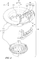
- FIG. 2 is an exploded perspective view of the rotor 20 of the rotary connector device 1.
- the rotor 20 includes a rotor main body 21.
- the rotor main body 21 includes a rotating plate 21A, a cylindrical portion 21B, and a sleeve 21C.
- the rotating plate 21A has a generally annular shape.
- the cylindrical portion 21B extends from the inner peripheral portion of the rotating plate 21A along the rotation axis A1, and includes a through-hole 21D through which the steering shaft passes.
- the through-hole 21D extends along the rotation axis A1.
- the sleeve 21C has an annular shape and is attached to the cylindrical portion 21B.
- the rotor 20 includes a connector housing 22.
- the connector housing 22 has a connector housing space 22A that houses the electrical connector 30 ( FIG. 7 ).
- the connector housing space 22A includes a plurality of housing spaces 22A1 to 22A3.
- the connector housing 22 may also be referred to as a rotor-side connector housing 22.
- the connector housing 22 includes a first connector holder 24 and a second connector holder 25.
- the second connector holder 25 is a separate member from the first connector holder 24, and is attached to the first connector holder 24.
- the first connector holder 24 extends from the rotor main body 21 along an axial direction D1 parallel to the rotation axis A1.
- the rotary connector device 1 includes a stator-side connector housing 40 and a housing cover 45.
- the stator-side connector housing 40 and the housing cover 45 are attached to the stator 10.
- the stator-side connector housing 40 houses a stator-side electrical connector that is connected to electrical devices (for example, a control device and a battery) provided in the vehicle body.
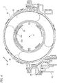
- FIG. 4 is a cross-sectional view of the rotary connector device 1 taken along line IV-IV of FIG. 1 .
- the stator 10 and the rotor 20 define a cable housing space 50 between the stator 10 and the rotor 20, in which the cable housing space 50 is provided so as to surround the rotation axis A1.
- the cable housing space 50 is annular and extends in a circumferential direction D2 relative to the rotation axis A1.
- the rotary connector device 1 includes an electrical cable 60.
- the electrical cable 60 is disposed in the cable housing space 50 and is electrically connected to the stator-side connector housing 40 ( FIG. 2 ).
- the electrical cable 60 is flexible and has a flat shape.
- the electrical cable 60 is also referred to as a flexible flat cable.
- FIG. 5 is a cross-sectional view of the connector housing 22.
- the first connector holder 24 extends from the rotor main body 21 to the opposite side of the cable housing space 50 along the rotation axis A1.
- the first connector holder 24 extends from the rotor main body 21 along the axial direction D1 parallel to the rotation axis A1.
- the first connector holder 24 is integrally formed with the rotating plate 21A and the cylindrical portion 21B of the rotor main body 21 as one single member.
- the first connector holder 24 may be a separate member from the rotating plate 21A and the cylindrical portion 21B.
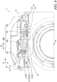
- FIG. 6 is a top view of the connector housing 22.
- the connector housing 22 includes a housing outer surface 22B.
- the housing outer surface 22B is disposed so as to surround the connector housing space 22A when viewed along the rotation axis A1.
- the housing outer surface 22B includes a first outer surface 22C, a second outer surface 22D, a third outer surface 22E, and a fourth outer surface 22F.
- the first outer surface 22C faces the rotation axis A1.
- the second outer surface 22D is disposed opposite to the first outer surface 22C relative to the connector housing space 22A so as to face radially outward.
- the third outer surface 22E is disposed between the first outer surface 22C and the second outer surface 22D so as to face in a direction different from the direction in which the first outer surface 22C faces.
- the fourth outer surface 22F is disposed opposite to the third outer surface 22E relative to the connector housing space 22A.
- FIG. 7 is a cross-sectional view of the connector housing 22.
- a length L3 of the third outer surface 22E is shorter than a length L2 of the second outer surface 22D.
- the length L3 of the third outer surface 22E is shorter than a length L1 of the first outer surface 22C.
- the length of the fourth outer surface 22F is shorter than the length of the second outer surface 22D.
- the length of the fourth outer surface 22F is shorter than the length of the first outer surface 22C.
- the relationship between the lengths L1 to L4 is not limited to the present embodiment.
- the connector housing 22 has a longitudinal direction D3. When viewed along the axial direction D1, the connector housing 22 has an elongated cross-sectional shape in the longitudinal direction D3.
- the lengths L1 and L2 are defined along the longitudinal direction D3.
- the lengths L3 and L4 are defined in a direction D4 orthogonal to the axial direction D1 and the longitudinal direction D3.
- the direction D4 may also be referred to as a first direction D4.
- the longitudinal direction D3 may also be referred to as a second direction D3.
- the second outer surface 22D is provided only on the first connector holder 24 among the first connector holder 24 and the second connector holder 25.
- the third outer surface 22E is provided on the first connector holder 24 and the second connector holder 25.
- the fourth outer surface 22F is provided only on the first connector holder 24 among the first connector holder 24 and the second connector holder 25.
- the fourth outer surface 22F may be provided on the first connector holder 24 and the second connector holder 25.
- the connector housing 22 includes a first gap S1.
- the first gap S1 is provided between the first connector holder 24 and the second connector holder 25, and extends from the housing outer surface 22B toward the connector housing space 22A.
- the first gap S1 is exposed from the housing outer surface 22B.
- the first gap S1 extends from one of the third outer surface 22E and the fourth outer surface 22F toward the connector housing space 22A.
- the first gap S1 extends from the third outer surface 22E toward the connector housing space 22A.
- the first gap S1 is exposed from the third outer surface 22E.
- the first gap S1 may be exposed from the fourth outer surface 22F or may extend from the fourth outer surface 22F toward the connector housing space 22A.
- One of the first connector holder 24 and the second connector holder 25 includes a first recess C1.
- the other of the first connector holder 24 and the second connector holder 25 includes a first protrusion V1 provided in the first recess C1.
- the first connector holder 24 includes the first recess C1
- the second connector holder 25 includes the first protrusion V1.
- the second connector holder 25 may include the first recess C1
- the first connector holder 24 may include the first protrusion V1.
- the first recess C1 and the first protrusion V1 may be omitted from the connector housing 22.
- the first gap S1 is provided at least partially between the first recess C1 and the first protrusion V1.
- the first recess C1 and the first protrusion V1 are disposed between the housing outer surface 22B and the connector housing space 22A.
- the first gap S1 is partially provided between the first recess C1 and the first protrusion V1.
- the first gap S1 may be entirely provided between the first recess C1 and the first protrusion V1.
- the first connector holder 24 includes a first holder main body 24A.
- the first holder main body 24A includes the first recess C1, the connector housing space 22A, and a holder housing space 24B.
- the first recess C1 is connected to the holder housing space 24B.
- the second connector holder 25 is at least partially disposed in the holder housing space 24B.
- the connector housing 22 includes a second gap S2.
- the second gap S2 is provided between the first connector holder 24 and the second connector holder 25, and extends from the housing outer surface 22B toward the connector housing space 22A.
- the second gap S2 is exposed from the housing outer surface 22B.
- the second gap S2 extends from the first outer surface 22C toward the connector housing space 22A.
- the second gap S2 is exposed from the first outer surface 22C.
- the second gap S2 may be exposed from one of the second outer surface 22D, the third outer surface 22E, and the fourth outer surface 22F, and may extend from one of the second outer surface 22D, the third outer surface 22E, and the fourth outer surface 22F toward the connector housing space 22A.
- the second gap S2 may be omitted from the connector housing 22.
- One of the first connector holder 24 and the second connector holder 25 includes a second recess C2.
- the other of the first connector holder 24 and the second connector holder 25 includes a second protrusion V2 provided in the second recess C2.
- the first connector holder 24 includes the second recess C2
- the second connector holder 25 includes the second protrusion V2.
- the second connector holder 25 may include the second recess C2 and the first connector holder 24 may include the second protrusion V2.
- the second recess C2 and the second protrusion V2 may be omitted from the connector housing 22.
- the second gap S2 is provided at least partially between the second recess C2 and the second protrusion V2.
- the second recess C2 and the second protrusion V2 are disposed between the housing outer surface 22B and the connector housing space 22A.
- the second gap S2 is entirely provided between the second recess C2 and the second protrusion V2.
- the second gap S2 may be partially provided between the second recess C2 and the second protrusion V2.
- the first holder main body 24A includes the second recess C2.
- the second recess C2 is disposed on the first outer surface 22C.
- the second protrusion V2 protrudes from a fourth wall 25F toward a first wall 25B.
- the connector housing 22 includes a third gap S3.
- the third gap S3 is provided between the first connector holder 24 and the second connector holder 25.
- the third gap S3 is not exposed from the housing outer surface 22B, and is provided inside the housing outer surface 22B.
- the third gap S3 may be exposed from the housing outer surface 22B or may extend from the housing outer surface 22B to the connector housing space 22A.
- One of the first connector holder 24 and the second connector holder 25 includes a third recess C3.
- the other of the first connector holder 24 and the second connector holder 25 includes a third protrusion V3 provided in the third recess C3.
- the first connector holder 24 includes the third recess C3, and the second connector holder 25 includes the third protrusion V3.
- the first wall 25B of the second connector holder 25 includes the third protrusion V3.
- the second connector holder 25 may include the third recess C3, and the first connector holder 24 may include the third protrusion V3.
- the third recess C3 and the third protrusion V3 may be omitted from the connector housing 22.
- the third gap S3 is provided at least partially between the third recess C3 and the third protrusion V3.
- the third recess C3 and the third protrusion V3 are disposed between the housing outer surface 22B and the connector housing space 22A.
- the third gap S3 is entirely provided between the third recess C3 and the third protrusion V3.
- the third gap S3 may be partially provided between the third recess C3 and the third protrusion V3.
- the first holder main body 24A includes the third recess C3.
- the third recess C3 is connected to the holder housing space 24B.
- the third recess C3 is disposed between the second recess C2 and the connector housing space 22A.
- the third protrusion V3 is disposed between the second protrusion V2 and the connector housing space 22A.
- the arrangement of the third recess C3 and the third protrusion V3 is not limited to the present embodiment.
- One of the first connector holder 24 and the second connector holder 25 includes a fourth recess C4.
- the other of the first connector holder 24 and the second connector holder 25 includes a fourth protrusion V4 provided in the fourth recess C4.
- the first connector holder 24 includes the fourth recess C4, and the second connector holder 25 includes the fourth protrusion V4.
- the first wall 25B of the second connector holder 25 includes a fourth protrusion V4.
- the second connector holder 25 may include the fourth recess C4, and the first connector holder 24 may include the fourth protrusion V4.
- the fourth recess C4 and the fourth protrusion V4 may be omitted from the connector housing 22.
- the first gap S1 is provided at least partially between the fourth recess C4 and the fourth protrusion V4.
- the fourth recess C4 and the fourth protrusion V4 are disposed between the housing outer surface 22B and the connector housing space 22A.
- the first gap S1 is partially provided between the fourth recess C4 and the fourth protrusion V4.
- the first gap S1 may be entirely provided between the fourth recess C4 and the fourth protrusion V4.
- the fourth recess C4 is disposed between the first recess C1 and the connector housing space 22A.
- the fourth protrusion V4 is disposed between the first protrusion V1 and the connector housing space 22A.
- the arrangement of the fourth recess C4 and the fourth protrusion V4 is not limited to the present embodiment.
- FIG. 8 is a perspective view of the connector housing 22.
- the first gap S1 extends along the rotation axis A1.
- the first gap S1 extends along the axial direction D1 in the third outer surface 22E.
- the second gap S2 extends along the rotation axis A1.
- the second gap S2 extends in the first outer surface 22C along the rotation axis A1 (along the axial direction D1).
- FIG. 9 is an exploded perspective view of the second connector holder 25 and the electrical connector 30.
- the electrical connector 30 includes a first connector 31 and a second connector 32.
- the first connector 31 includes a plurality of bus bars 31A and a bus bar case 31B.
- the plurality of bus bars 31A are made of metals
- the bus bar case 31B is made of resins.
- the plurality of bus bars 31A protrude from the bus bar case 31B along the axial direction D1.
- the bus bar case 31B holds the plurality of bus bars 31A.
- the second connector 32 includes a plurality of bus bars 32A and a bus bar case 32B.
- the plurality of bus bars 32A are made of metals, and the bus bar case 32B is made of resins.
- the plurality of bus bars 32A protrude from the bus bar case 32B along the axial direction D1.
- the bus bar case 32B holds the plurality of bus bars 32A.
- the plurality of bus bars 31A and 31B are electrically connected to the electrical cable 60 (see FIG. 4 ).
- the second connector holder 25 includes a second holder main body 25A, the first wall 25B, and a second wall 25C.
- the second holder main body 25A includes a connector support portion 25D that supports the electrical connector 30.
- the electrical connector 30 is disposed on the connector support portion 25D.
- the first wall 25B extends from the second holder main body 25A along the axial direction D1 parallel to the rotation axis A1.
- the second wall 25C extends from the second holder main body 25A along the axial direction D1 and is coupled to the first wall 25B.
- the first wall 25B extends in the first direction D4 orthogonal to the axial direction D1.
- FIG. 10 is a cross-sectional view of the connector housing 22.
- the first wall 25B is disposed between the connector housing space 22A and the first gap S1.
- the second wall 25C is disposed opposite to the first gap S1 relative to the first wall 25B.
- the second wall 25C extends from the first wall 25B in the second direction D3 that is orthogonal to the axial direction D1 and different from the first direction D4.
- the second wall 25C extends from the first wall 25B opposite to the first gap S1, and is disposed in the connector housing space 22A.
- the first wall 25B includes a first wall surface 25B1 facing the electrical connector 30.
- the first wall 25B includes a third wall surface 25B2 provided on the back side of the first wall surface 25B1.
- the first wall surface 25B1 and the third wall surface 25B2 face the second direction D3.
- the second wall 25C extends from the first wall surface 25B1 in the second direction D3.
- the second wall 25C includes a second wall surface 25C1 and a fourth wall surface 25C2.
- the second wall surface 25C1 faces the electrical connector 30.
- the fourth wall surface 25C2 is provided on the back side of the second wall surface 25C1.
- the second wall surface 25C1 and the fourth wall surface 25C2 face the first direction D4.
- the second direction D3 is orthogonal to the first direction D4.
- the second direction D3 may or may not be substantially orthogonal to the first direction D4.
- the first wall 25B has a first length AL11 defined in the first direction D4.
- the second wall 25C has a second length AL21 defined in the second direction D3.
- the second length AL21 is greater than the first length AL11.
- the second length AL21 may be less than or equal to the first length AL11.
- the second connector holder 25 includes a first rib 25R1 and a second rib 25R2.
- the first rib 25R1 extends from the second wall 25C toward opposite to the electrical connector 30.
- the second rib 25R2 extends from the second wall 25C toward opposite to the electrical connector 30, and is spaced apart from the first rib 25R1 in the second direction D3.
- the first rib 25R1 and the second rib 25R2 protrude from the fourth wall surface 25C2 of the second wall 25C in the first direction D4.
- at least one of the first rib 25R1 and the second rib 25R2 may be omitted from the second connector holder 25.
- the first connector holder 24 includes a holder coupling portion 24K that couples the first connector holder 24 to the second wall 25C.
- the holder coupling portion 24K protrudes from the first holder main body 24A toward the second holder main body 25A along the axial direction D1.
- the holder coupling portion 24K includes a coupling groove 24K1.
- the second connector holder 25 includes a coupling protrusion 25K provided on the second wall 25C.
- the holder coupling portion 24K is hooked to the coupling protrusion 25K so as to couple the first connector holder 24 to the second connector holder 25.
- the coupling protrusion 25K is disposed between the first rib 25R1 and the second rib 25R2 in the second direction D3.
- the coupling protrusion 25K is provided on the fourth wall surface 25C2.
- the coupling protrusion 25K protrudes from the fourth wall surface 25C2 in the first direction D4.
- the coupling protrusion 25K is disposed in the coupling groove 24K1 of the holder coupling portion 24K.
- FIG. 12 is a cross-sectional view of the connector housing 22.
- the first wall 25B has a first axial length AL12 defined from the second holder main body 25A in the axial direction D1.
- the second wall 25C has a second axial length AL22 defined from the second holder main body 25A in the axial direction D1.
- the second axial length AL22 is shorter than the first axial length AL12.
- the second length AL21 is longer than the second axial length AL22.
- the second axial length AL22 can also be equal to or longer than the first axial length AL12.
- the second length AL21 may be equal to or shorter than the second axial length AL22.
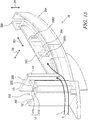
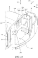
- FIG. 13 is a perspective view of the second connector holder 25.
- the second connector holder 25 includes a third wall 25E and the fourth wall 25F.
- the fourth wall 25F is spaced apart from the first wall 25B in the second direction D3.
- the third wall 25E extends from the fourth wall 25F to the first wall 25B in the second direction D3 and couples the fourth wall 25F to the first wall 25B.
- the third wall 25E extends from the first wall 25B toward opposite to the second wall 25C in the second direction D3.
- the first protrusion V1 protrudes from the third wall 25E.
- the first protrusion V1 includes a first base VIA and a first extension V1B.
- the first base VIA protrudes from the third wall 25E along the first direction D4.
- the first extension V1B is spaced apart from the third wall 25E in the first direction D4.
- the first extension V1B extends from the tip of the first base VIA along the third wall 25E (along the longitudinal direction D3).
- the first extension V1B extends from the tip of the first base VIA toward the fourth protrusion V4.
- the first protrusion V1 extends along the axial direction D1.
- the fourth protrusion V4 extends along the axial direction D1. As illustrated in FIG. 7 , the first extension V1B extends from the first base VIA toward the connector housing space 22A.
- FIG. 14 is a perspective view of the second connector holder 25.
- the first wall 25B, the third wall 25E, and the fourth wall 25F define an internal space 25S.
- the second connector holder 25 includes a first holder coupling portion 25G, a second holder coupling portion 25H, and a third holder coupling portion 25J.
- the first holder coupling portion 25G is disposed in the internal space 25S.
- the second holder coupling portion 25H extends from the second holder main body 25A along the axial direction D1.
- the third holder coupling portion 25J extends from the second holder main body 25A along the axial direction D1.
- the first connector holder 24 includes a first coupling protrusion 24D and a second coupling protrusion 24E. As illustrated in FIG. 5 , the first coupling protrusion 24D protrudes from the first holder main body 24A. The first holder coupling portion 25G is hooked to the first coupling protrusion 24D.
- FIGS. 15 and 16 are cross-sectional views of the connector housing 22.
- the second coupling protrusion 24E protrudes from the first holder main body 24A.
- the second holder coupling portion 25H is hooked to the second coupling protrusion 24E.
- the third holder coupling portion 25J is hooked to the cylindrical portion 21B of the rotor main body 21.
- the second connector holder 25 is attached to the first connector holder 24.
- FIGS. 17 and 18 are perspective views of the first connector holder 24. As illustrated in FIG. 17 , the first recess C1, the second recess C2, and the fourth recess C4 extend along the axial direction D1. As illustrated in FIG. 18 , the third recess C3 extends along the axial direction D1.
- FIG. 19 is a cross-sectional view of the connector housing 22.
- the connector housing space 22A includes a housing space 22A4.
- the housing space 22A4 communicates with the housing spaces 22A1 to 22A3 ( FIG. 7 ).
- the electrical connector 30 and the connector support portion 25D of the second connector holder 25 are disposed in the housing space 22A4.
- the first gap S1 extends from the third outer surface 22E to the housing space 22A4.
- the third gap S3 extends from the holder housing space 24B (internal space 25S) to the housing space 22A4.
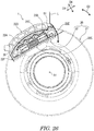
- FIG. 20 is a cross-sectional view of the connector housing 22.
- the connector housing 22 includes a fourth gap S4.
- the fourth gap S4 is provided between the first connector holder 24 and the second connector holder 25. More specifically, the first connector holder 24 includes a curved wall 24C.
- the fourth gap S4 is provided between the curved wall 24C and the connector support portion 25D.
- the fourth gap S4 extends along the curved wall 24C.
- the curved wall 24C extends from the first holder main body 24A along the axial direction D1.
- FIG. 21 is a perspective view of the connector housing 22. As illustrated in FIG. 21 , the fourth gap S4 is connected to the first gap S1. Note that the fourth gap S4 may be omitted.
- the features of the rotary connector device 1 are as follows.
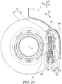
- the second outer surface 22D faces upward, and the third outer surface 22E and the fourth outer surface 22F face in the lateral direction. Therefore, even when a liquid L is spilled from the upper side of the rotary connector device 1 in the neutral state, the liquid L can be suppressed from reaching the connector housing space 22A through the first gap S1.
- the second outer surface 22D faces the lateral direction
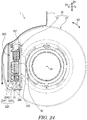
- the third outer surface 22E faces the downward direction. Therefore, even when the liquid L is spilled from the upper side of the rotary connector device 1 in the first rotation state, the liquid L can be suppressed from reaching the connector housing space 22A through the first gap S1.
- the second outer surface 22D is provided only on the first connector holder 24 among the first connector holder 24 and the second connector holder 25. That is, since the gap between the first connector holder 24 and the second connector holder 25 does not exist on the second outer surface 22D, the environmental resistance of the rotary connector device 1 can be further enhanced.
- the first gap S1 extends from the third outer surface 22E toward the connector housing space 22A.
- the fourth outer surface 22F is provided only on the first connector holder 24 among the first connector holder 24 and the second connector holder 25. That is, since the gap between the first connector holder 24 and the second connector holder 25 does not exist on the fourth outer surface 22F, the environmental resistance of the rotary connector device 1 can be further enhanced.
- the first protrusion V1 is inserted into the first recess C1
- the fourth protrusion V4 adjacent to the first protrusion V1 and the first recess C1 is inserted into the fourth recess C4. Therefore, the shape of the first gap S1 can take a more complicated shape. Accordingly, in the direction (substantially the second direction D3) in which the liquid flows from the third outer surface 22E to the connector housing space 22A, the uneven structure can be doubly provided between the third outer surface 22E and the connector housing space 22A.
- the fourth protrusion V4 is inserted into the fourth recess C4 in the first direction D4 different from the second direction D3. Therefore, it is possible to make the protruding direction of the double uneven structure different in the direction (substantially the second direction D3) in which the liquid flows from the third outer surface 22E to the connector housing space 22A. Therefore, by providing the labyrinth structure as illustrated in FIG. 7 in the connector housing 22, it is possible to more effectively suppress the liquid entering the first gap S1 from reaching the connector housing space 22A.
- the second outer surface 22D faces the lateral direction
- the third outer surface 22E faces the upward direction.
- the length L3 of the third outer surface 22E is shorter than the length L2 of the second outer surface 22D, even when the liquid is spilled from the upper side of the rotary connector device 1 in the second rotation state, it is possible to suppress the liquid from reaching the connector housing space 22A through the first gap S1.
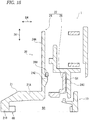
- the first wall 25B and the second wall 25C can suppress the liquid entering the connector housing space 22A through the first gap S1 from reaching the electrical connector 30 (see also FIG. 13 ).
- the first wall 25B and the second wall 25C can suppress the liquid entering the connector housing space 22A through the first gap S1 from reaching the electrical connector 30 in the second rotation state (see also FIG. 13 ).
- the second wall 25C can be used to couple the first connector holder 24 and the second connector holder 25.
- the second connector holder 25 includes the coupling protrusion 25K provided on the second wall 25C.
- the holder coupling portion 24K is hooked to the coupling protrusion 25K so as to couple the first connector holder 24 to the second connector holder 25. Therefore, the coupling strength between the first connector holder 24 and the second connector holder 25 can be enhanced by using the second wall 25C.
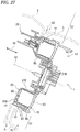
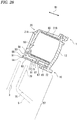
- FIGS. 27 to 29 illustrate variations of the rotary connector device 1.
- the rotary connector device 1 includes a cable housing 13.
- the cable housing 13 includes the stator 10 and the rotor 20.
- the cable housing 13 is formed in a circular shape.
- a through-hole 21D is formed at the center of the cable housing 13.
- the through-hole 21D is provided so as to penetrate the cable housing 13 in the axial direction D1.
- the entire housing of the rotary connector device 1 may be configured as the cable housing 13, or a part of the housing may be configured as the cable housing 13.
- FIG. 28 is an enlarged view of a part of the lower side of FIG. 27 .
- the stator 10 includes an annular stationary-side ring plate 12 and a cylindrical outer peripheral wall (outer peripheral portion) 14 provided at an outer peripheral edge portion of the stationary-side ring plate 12.
- the rotor 20 includes the annular rotating plate 21A and the cylindrical portion 21B having a cylindrical shape and provided on an inner peripheral edge portion of the rotating plate 21A.
- each of the stationary-side ring plate 12 and the rotating plate 21A has an annular shape.
- the outer peripheral wall 14 and the cylindrical portion 21B each has a cylindrical shape.
- the stationary-side ring plate 12 is disposed such that the thickness direction thereof faces the axial direction D1.
- the rotating plate 21A is arranged such that its thickness direction is oriented in the same direction as the stationary-side ring plate 12.
- the outer diameter of the rotating plate 21A is slightly smaller than the outer diameter of the stationary-side ring plate 12.
- the rotating plate 21A and the stationary-side ring plate 12 are disposed at positions separated from each other by a predetermined distance so as to face each other in the axial direction D1.
- the outer peripheral wall 14 extends from an outer peripheral edge portion of the stationary-side ring plate 12 to one side of the axial direction D1.
- the cylindrical portion 21B extends from the inner peripheral edge portion of the rotating plate 21A to the other side of the axial direction D1.
- the cylindrical portion 21B has an outer diameter smaller than the inner diameter of the outer peripheral wall 14.
- the outer peripheral wall 14 is located radially outward of the cylindrical portion 21B.
- the outer peripheral wall 14 and the cylindrical portion 21B are disposed at positions separated from each other by a predetermined distance so as to face each other in the radial direction.
- the cable housing space 50 is formed between the stator 10 and the rotor 20 attached to the stator 10.
- the cable housing space 50 is an annular space surrounded by: the stationary-side ring plate 12 and the rotating plate 21A that face each other in the axial direction D1; and the outer peripheral wall 14 and the cylindrical portion 21B that face each other in the radial direction.
- the outer peripheral wall 14 is disposed such that one end portion 51 in the axial direction D1 faces an outer peripheral edge portion 53 of the rotating plate 21A in the radial direction.
- the one end portion 51 of the outer peripheral wall 14 in the axial direction D1 and the outer peripheral edge portion 53 of the rotating plate 21A are arranged at a predetermined interval in the radial direction. Thus, an intermediate gap 55 is formed between them.
- the intermediate gap 55 opens to one side in the axial direction D1.
- the intermediate gap 55 extends in the circumferential direction of the outer peripheral wall 14 and the rotating plate 21A.
- the intermediate gap 55 is formed in an annular shape in the vicinity of the outer edge portion of the cable housing 13.
- the intermediate gap 55 connects an external space 57 of the cable housing 13 and the cable housing space 50.
- the intermediate gap 55 connects the external space 57 of the cable housing 13 and the cable housing space 50 to each other via a passage 59 formed between the outer peripheral wall 14 and the rotating plate 21A.
- a discharge hole 61 is formed in the outer peripheral wall 14.
- the discharge hole 61 opens toward the outside of the cable housing 13 in the radial direction. That is, the discharge hole 61 is an opening different from the intermediate gap 55 in the cable housing 13 and opens in a direction different from the opening of the intermediate gap 55.
- the discharge hole 61 connects the external space 57 of the cable housing 13 and the internal space of a discharge groove 71 to each other.
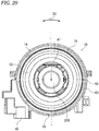
- FIG. 29 is a partial cross-sectional side view of the stator 10.
- the outer peripheral wall 14 has a double structure in the present variation.
- the outer peripheral wall 14 includes a first outer-circumferential cylindrical portion 63 in a cylindrical shape and a second outer-circumferential cylindrical portion 65 in a cylindrical shape.
- the second outer-circumferential cylindrical portion 65 has an outer diameter smaller than the inner diameter of the first outer-circumferential cylindrical portion 63, and is provided radially inside the first outer-circumferential cylindrical portion 63.
- the first outer-circumferential cylindrical portion 63 and the second outer-circumferential cylindrical portion 65 are disposed at positions separated from each other by a predetermined distance so as to face each other in the radial direction, and are disposed coaxially.
- the coupling portion 67 divides a space formed between the first outer-circumferential cylindrical portion 63 and the second outer-circumferential cylindrical portion 65 into two in the axial direction D1.
- the discharge groove 71 and an additional groove 72 are formed between the first outer-circumferential cylindrical portion 63 and the second outer-circumferential cylindrical portion 65.
- the discharge groove 71 is disposed on one side of the coupling portion 67 in the axial direction D1.
- the additional groove 72 is disposed on the other side of the coupling portion 67 in the axial direction D1.
- the discharge groove 71 opens on one side in the axial direction such that the opening thereof faces the intermediate gap 55.
- the discharge groove 71 extends along the first outer-circumferential cylindrical portion 63 and the second outer-circumferential cylindrical portion 65.
- the discharge groove 71 has a circumferential length of at least about half the circumferential length of the outer peripheral wall 14.
- the discharge groove 71 functions as a dust pool that retains foreign matter such as sand that has entered the rotary connector device 1.
- the discharge groove 71 is connected to the external space 57 of the cable housing 13 via the intermediate gap 55.
- the discharge groove 71 is also connected to the cable housing space 50 via the passage 59.
- the discharge hole 61 is formed in the first outer-circumferential cylindrical portion 63.
- the discharge hole 61 radially penetrates the first outer-circumferential cylindrical portion 63 in the radial direction.
- the discharge hole 61 connects the internal space of the discharge groove 71 extending continuously in the circumferential direction of the outer peripheral wall 14 to the external space 57 of the cable housing 13.
- the discharge hole 61 is disposed on one side (discharge groove 71 side) in the axial direction D1 relative to the coupling section with the coupling portion 67, in the first outer-circumferential cylindrical portion 63 in the axial direction D1.
- the discharge hole 61 is disposed so as to be connected to the deepest portion (a bottom portion 87) of the discharge groove 71. Further, when the rotary connector device 1 is installed, the discharge hole 61 is disposed so as to be positioned in the vicinity of the lowermost portion of the discharge groove 71, in the circumferential direction of the outer peripheral wall 14.
- the inside of the discharge groove 71 is a space which is long and continuous in an arc shape between the lowermost portion where the discharge hole 61 is disposed and a portion (a portion positioned at the uppermost portion) whose phase is different by 180° from the lowermost portion.
- the discharge hole 61 faces the internal space 75 of a column cover 5 in the external space 57 of the cable housing 13. At this time, one end portion 77 in the axial direction D1 of the discharge hole 61 is disposed at a position facing the internal space 75 of the column cover 5 or a lower end portion 79 of the column cover 5 in the axial direction.
- the discharge hole 61 has a slit shape.
- FIG. 27 illustrates a state in which the rotary connector device 1 is provided at a predetermined position of the steering column.
- liquid such as water enters the inside from an upper gap 82 among the gaps generated between a steering lower cover 3 and the column cover 5. This liquid is applied to the vicinity of the upper portion of the outer periphery of the rotary connector device 1.
- a part of the liquid enters the internal space of the cable housing 13 of the rotary connector device 1 through the intermediate gap 55.
- FIG. 29 illustrates a state in which the liquid entering the uppermost end portion of the intermediate gap 55 flows to the lowermost end portion along the discharge groove 71.
- the discharge hole 61 is located near the bottom portion 87 of the discharge groove 71. Therefore, the liquid that has reached the lowermost end portion of the discharge groove 71 is discharged through the discharge hole 61 with little accumulation at the lowermost end portion. Since the liquid does not accumulate in the lower portion of the discharge groove 71, the liquid level does not rise in the lower portion of the discharge groove 71 and the liquid does not overflow into the cable housing space 50. Therefore, since a liquid such as water is not applied to the primary mold of the core wire welding portion of the electrical cable 60 disposed in the cable housing space 50, insulation failure can be suppressed.
- the rotary connector device 1 of the present variation includes the stator 10, the rotor 20, and the electrical cable 60.
- the rotor 20 is relatively rotatably attached to the stator 10 while being positioned inside the stator 10 such that the annular cable housing space 50 is formed between the rotor 20 and the stator 10.
- the electrical cable 60 is housed in the cable housing space 50.
- the electrical cable 60 electrically connects the stator-side connector housing 40 provided in the stator 10 and the connector housing 22 provided in the rotor 20.
- the intermediate gap 55 connecting the external space 57 of the cable housing 13 composed of the stator 10 and the rotor 20 to the cable housing space 50 is formed between the stator 10 and the rotor 20.
- the stator 10 includes the outer peripheral wall 14 provided radially outside the cable housing space 50.
- the outer peripheral wall 14 includes: the discharge groove 71 provided radially outside the cable housing space 50 and extending in the circumferential direction; and the discharge hole 61 connected to the discharge groove 71.
- the discharge groove 71 is connected to the intermediate gap 55 and the cable housing space 50.
- the discharge hole 61 connects the discharge groove 71 and the external space 57.
- the rotary connector device 1 by installing the rotary connector device 1 such that the discharge hole 61 is positioned at the lower portion, even when liquid such as water enters the inside from the intermediate gap 55 between the stator 10 and the rotor 20, the liquid can be reliably and quickly discharged using the discharge hole 61 after being preferentially guided to the discharge groove 71. Therefore, insulation failure in the rotary connector device 1 can be suppressed.
- the discharge groove 71 is provided continuously over a half circumference or more from the position connected to the discharge hole 61.
- the liquid can be discharged from the discharge hole 61 at or near the lower portion of the rotary connector device 1 through the discharge groove 71.
- the discharge hole 61 may include not only one hole but also a plurality of holes 61A.
- the liquid can be smoothly discharged.
- the discharge hole 61 includes a slit.
- the discharge hole 61 includes a slit.
- the shape of the discharge hole 61 is freely selectable, and may be, for example, a circular shape, a square shape, or the like.
- the discharge hole 61 may be formed in a notch shape that opens the end portion of the first outer-circumferential cylindrical portion 63 on the side close to the opening of the discharge groove 71 (a notch for discharge is also included as the discharge hole).
- the direction in which the discharge hole 61 is formed so as to pass through the first outer-circumferential cylindrical portion 63 may be the radial direction as in the above-described variation, or may be a direction inclined from the radial direction.
- the plurality of discharge holes 61 may be formed so as to be concentrated in the vicinity of the lowermost portion, or may be formed so as to be arranged in a wide range in the circumferential direction.
- the discharge groove 71 is preferably formed continuously over a half circumference or more as described above, but may be formed less than a half circumference.
- a number such as “first” or “second” is merely a term for identifying a configuration, and does not have any other meaning (e.g., a particular order, or the like).
- first element does not imply that a “second element” exists
- second element does not imply that a "first element” exists.
- the expression "at least one of A and B” in the present disclosure encompasses, for example, all of (1) only A, (2) only B, and (3) both A and B.
- the expression “at least one of A, B, and C” encompasses, for example, all of (1) only A, (2) only B, (3) only C, (4) A and B, (5) B and C, (6) A and C, and (7) all of A, B, and C.
- the expression “at least one of A and B" is not interpreted as "at least one of A and at least one of B.”
Landscapes
- Engineering & Computer Science (AREA)
- Mechanical Engineering (AREA)
- Connector Housings Or Holding Contact Members (AREA)
- Details Of Connecting Devices For Male And Female Coupling (AREA)
- Motor Or Generator Frames (AREA)
Abstract
Description
- The technology disclosed in the present application relates to a rotary connector device.
- A rotary connector device used for vehicles is known (e.g., see
Patent Document 1 and 2). -
- Patent Document 1:
WO 2018/047581 - Patent Document 2:
JP 5065508 B - To adapt the rotary connector device to various vehicles, it is preferable to enhance the environmental resistance of the rotary connector device.
- An object of the technology disclosed in the present application is to enhance the environmental resistance of the rotary connector device.
- A rotary connector device according to a first aspect includes a stator, a rotor, and an electrical connector. The rotor is provided so as to be rotatable about a rotation axis relative to the stator. The electrical connector is attached to the rotor. The stator and the rotor define a cable housing space between the stator and the rotor, wherein the cable housing space is provided so as to surround the rotation axis. The rotor includes: a rotor main body; and a connector housing having a connector housing space that houses the electrical connector. The connector housing includes a first connector holder and a second connector holder. The first connector holder extends from the rotor main body to opposite to the cable housing space along the rotation axis. The second connector holder is a separate member from the first connector holder and is attached to the first connector holder. The second connector holder includes a second holder main body, a first wall, and a second wall. The second holder main body includes a connector support portion that supports the electrical connector. The first wall extends from the second holder main body along an axial direction parallel to the rotation axis. The second wall extends from the second holder main body along the axial direction and is coupled to the first wall.
- A rotary connector device according to a second aspect is the rotary connector device according to the first aspect, wherein the connector housing includes: a housing outer surface disposed so as to surround the connector housing space when viewed along the rotation axis; and a first gap provided between the first connector holder and the second connector holder and extending from the housing outer surface toward the connector housing space.
- A rotary connector device according to a third aspect is the rotary connector device according to the second aspect, wherein the first wall extends in a first direction orthogonal to the axial direction, and is disposed between the connector housing space and the first gap. The second wall extends from the first wall in a second direction that is orthogonal to the axial direction and is different from the first direction, and is disposed opposite to the first gap relative to the first wall.
- In the rotary connector device according to the third aspect, since the second wall is disposed opposite to the first gap relative to the first wall, the first wall and the second wall can suppress the liquid entering the connector housing space from reaching the electrical connector. Therefore, the environmental resistance of the rotary connector device can be enhanced.
- A rotary connector device according to a fourth aspect is the rotary connector device according to the third aspect, wherein the second direction is orthogonal to the first direction.
- In the rotary connector device according to the fourth aspect, the first wall and the second wall can effectively suppress the liquid entering the connector housing space from reaching the electrical connector.
- A rotary connector device according to a fifth aspect is the rotary connector device according to the third or fourth aspect, wherein the first wall has a first length defined in the first direction. The second wall has a second length defined in the second direction. The second length is longer than the first length.
- In the rotary connector device according to the fifth aspect, the first wall and the second wall can effectively suppress the liquid entering the connector housing space from reaching the electrical connector.
- A rotary connector device according to a sixth aspect is the rotary connector device according to any one of the third to fifth aspects, wherein the first wall has a first axial length defined from the second holder main body in the axial direction. The second wall has a second axial length defined from the second holder main body in the axial direction. The second axial length is shorter than the first axial length.
- In the rotary connector device according to the sixth aspect, it is possible to effectively utilize the connector housing space while suppressing the liquid entering the connector housing space from reaching the electrical connector.
- A rotary connector device according to a seventh aspect is the rotary connector device according to any one of the third to sixth aspects, wherein the first connector holder includes a holder coupling portion that couples the first connector holder to the second wall.
- In the rotary connector device according to the seventh aspect, the second wall can be used to couple the first connector holder and the second connector holder.
- A rotary connector device according to an eighth aspect is the rotary connector device according to the seventh aspect, wherein the second connector holder includes a coupling protrusion provided on the second wall. The holder coupling portion is hooked to the coupling protrusion so as to couple the first connector holder to the second connector holder.
- In the rotary connector device according to the eighth aspect, the coupling strength between the first connector holder and the second connector holder can be enhanced by using the second wall.
- A rotary connector device according to a ninth aspect is the rotary connector device according to the eighth aspect, wherein the first wall includes a first wall surface facing the electrical connector. The second wall extends from the first wall surface in the second direction.
- In the rotary connector device according to the ninth aspect, the first wall and the second wall can effectively suppress the liquid entering the connector housing space from reaching the electrical connector.
- A rotary connector device according to a tenth aspect is the rotary connector device according to the ninth aspect, wherein the second wall includes: a second wall surface facing the electrical connector; and a fourth wall surface provided on a back side of the second wall surface. The coupling protrusion is provided on the fourth wall surface.
- In the rotary connector device according to the tenth aspect, the coupling strength between the first connector holder and the second connector holder can be enhanced by using the second wall.
- A rotary connector device according to an eleventh aspect is the rotary connector device according to any one of the eighth to tenth aspects, wherein the second connector holder includes a first rib and a second rib. The first rib extends from the second wall to opposite to the electrical connector. The second rib extends from the second wall to opposite to the electrical connector, and is spaced apart from the first rib in the second direction. The coupling protrusion is disposed between the first rib and the second rib in the second direction.
- In the rotary connector device according to the eleventh aspect, the coupling strength between the first connector holder and the second connector holder can be enhanced by using the second wall.
- A rotary connector device according to a twelfth aspect is the rotary connector device according to any one of the second to eleventh aspects, wherein the housing outer surface includes a first outer surface, a second outer surface, a third outer surface, and a fourth outer surface. The first outer surface faces toward the rotation axis. The second outer surface is disposed opposite to the first outer surface relative to the connector housing space so as to face radially outward. The third outer surface is disposed between the first outer surface and the second outer surface so as to face in a direction different from a direction wherein the first outer surface faces. The fourth outer surface is disposed on a side opposite to the third outer surface relative to the connector housing space. The first gap extends from one of the third outer surface and the fourth outer surface toward the connector housing space.
- In the rotary connector device according to the twelfth aspect, since the first gap extends from one of the third outer surface and the fourth outer surface toward the connector housing space, for example, in a case where liquid is spilled on the first surface or the second surface, it is easy to suppress the liquid from entering the connector housing space. Therefore, the environmental resistance of the rotary connector device can be enhanced.
- A rotary connector device according to a thirteenth aspect is the rotary connector device according to the twelfth aspect, wherein the first gap extends along the rotation axis.
- In the rotary connector device according to the thirteenth aspect, the coupling strength between the first connector holder and the second connector holder can be enhanced.
- A rotary connector device according to a fourteenth aspect is the rotary connector device according to the twelfth or thirteenth aspect, wherein the second outer surface is provided only on the first connector holder among the first connector holder and the second connector holder.
- In the rotary connector device according to the fourteenth aspect, since the gap between the first connector holder and the second connector holder does not exist on the second outer surface, the environmental resistance of the rotary connector device can be further enhanced.
- A rotary connector device according to a fifteenth aspect is the rotary connector device according to any one of the twelfth to fourteenth aspects, wherein the third outer surface is provided on the first connector holder and the second connector holder.
- In the rotary connector device according to the fifteenth aspect, the first gap provided between the first connector holder and the second connector holder can be provided in the third outer surface.
- A rotary connector device according to a sixteenth aspect is the rotary connector device according to any one of the twelfth to fifteenth aspects, wherein the first gap extends from the third outer surface toward the connector housing space. The fourth outer surface is provided only on the first connector holder among the first connector holder and the second connector holder.
- In the rotary connector device according to the sixteenth aspect, since the gap between the first connector holder and the second connector holder does not exist on the fourth outer surface, the environmental resistance of the rotary connector device can be further enhanced.
- A rotary connector device according to a seventeenth aspect is the rotary connector device according to any one of the twelfth to sixteenth aspects, wherein one of the first connector holder and the second connector holder includes a first recess. The other of the first connector holder and the second connector holder includes a first protrusion provided in the first recess.
- In the rotary connector device according to the seventeenth aspect, by providing the first recess and the first protrusion, the coupling strength between the first connector holder and the second connector holder can be enhanced.
- A rotary connector device according to an eighteenth aspect is the rotary connector device according to the seventeenth aspect, wherein the first gap is provided at least partially between the first recess and the first protrusion.
- In the rotary connector device according to the eighteenth aspect, the environmental resistance of the rotary connector device can be enhanced while increasing the coupling strength between the first connector holder and the second connector holder.
- A rotary connector device according to a nineteenth aspect is the rotary connector device according to the seventeenth or eighteenth aspect, wherein the first recess and the first protrusion are disposed between the housing outer surface and the connector housing space.
- In the rotary connector device according to the nineteenth aspect, the first recess and the first protrusion can be provided inside the connector housing, and the environmental resistance of the rotary connector device can be enhanced while increasing the coupling strength between the first connector holder and the second connector holder.
- A rotary connector device according to a twentieth aspect is the rotary connector device according to any one of the twelfth to nineteenth aspects, wherein the connector housing includes a second gap that is provided between the first connector holder and the second connector holder and extends from the housing outer surface toward the connector housing space.
- In the rotary connector device according to the twentieth aspect, the degree of design freedom of the first connector holder and the second connector holder can be enhanced by providing the second gap.
- A rotary connector device according to a twenty-first aspect is the rotary connector device according to the twentieth aspect, wherein one of the first connector holder and the second connector holder includes a second recess. The other of the first connector holder and the second connector holder includes a second protrusion provided in the second recess.
- In the rotary connector device according to the twenty-first aspect, by providing the second recess and the second protrusion, the coupling strength between the first connector holder and the second connector holder can be enhanced.
- A rotary connector device according to a twenty-second aspect is the rotary connector device according to the twenty-first aspect, wherein the second gap is provided at least partially between the second recess and the second protrusion.
- In the rotary connector device according to the twenty-second aspect, the environmental resistance of the rotary connector device can be enhanced while increasing the coupling strength between the first connector holder and the second connector holder.
- A rotary connector device according to a twenty-third aspect is the rotary connector device according to the twenty-first or twenty-second aspect, wherein the second recess and the second protrusion are disposed between the housing outer surface and the connector housing space.
- In the rotary connector device according to the twenty-third aspect, the second recess and the second protrusion can be provided inside the connector housing, and the environmental resistance of the rotary connector device can be enhanced while increasing the coupling strength between the first connector holder and the second connector holder.
- A rotary connector device according to a twenty-fourth aspect is the rotary connector device according to any one of the twelfth to twenty-third aspects, wherein the connector housing includes: a third gap provided between the first connector holder and the second connector holder.
- In the rotary connector device according to the twenty-fourth aspect, the degree of design freedom of the first connector holder and the second connector holder can be enhanced by providing the third gap.
- A rotary connector device according to a twenty-fifth aspect is the rotary connector device according to the twenty-fourth aspect, wherein one of the first connector holder and the second connector holder includes a third recess. The other of the first connector holder and the second connector holder includes a third protrusion provided in the third recess.
- In the rotary connector device according to the twenty-fifth aspect, by providing the third recess and the third protrusion, the coupling strength between the first connector holder and the second connector holder can be enhanced.
- A rotary connector device according to a twenty-sixth aspect is the rotary connector device according to the twenty-fifth aspect, wherein the third gap is provided at least partially between the third recess and the third protrusion.
- In the rotary connector device according to the twenty-sixth aspect, the environmental resistance of the rotary connector device can be enhanced while increasing the coupling strength between the first connector holder and the second connector holder.
- A rotary connector device according to a twenty-seventh aspect is the rotary connector device according to the twenty-fifth or twenty-sixth aspect, wherein the third recess and the third protrusion are disposed between the housing outer surface and the connector housing space.
- In the rotary connector device according to the twenty-seventh aspect, the third recess and the third protrusion can be provided inside the connector housing, and the environmental resistance of the rotary connector device can be enhanced while increasing the coupling strength between the first connector holder and the second connector holder.
- A rotary connector device according to a twenty-eighth feature is the rotary connector device according to any one of the twelfth to twenty-seventh features, wherein one of the first connector holder and the second connector holder includes a fourth recess. The other of the first connector holder and the second connector holder includes a fourth protrusion provided in the fourth recess.
- In the rotary connector device according to the twenty eighth aspect, by providing the fourth recess and the fourth protrusion, the coupling strength between the first connector holder and the second connector holder can be enhanced.
- A rotary connector device according to a twenty-ninth aspect is the rotary connector device according to the twenty-eighth aspect, wherein the first gap is provided at least partially between the fourth recess and the fourth protrusion.
- In the rotary connector device according to the twenty-ninth aspect, the environmental resistance of the rotary connector device can be enhanced while increasing the coupling strength between the first connector holder and the second connector holder.
- A rotary connector device according to a thirtieth aspect is the rotary connector device according to the twenty-eighth or twenty-ninth aspect, wherein the fourth recess and the fourth protrusion are disposed between the housing outer surface and the connector housing space.
- In the rotary connector device according to the thirtieth aspect, the fourth recess and the fourth protrusion can be provided inside the connector housing, and the environmental resistance of the rotary connector device can be enhanced while increasing the coupling strength between the first connector holder and the second connector holder.
- A rotary connector device according to a thirty-first aspect is the rotary connector device according to any one of the twelfth to thirtieth aspects, wherein a length of the third outer surface is shorter than a length of the second outer surface when viewed along the rotation axis.
- In the rotary connector device according to the thirty-first aspect, it is possible to shorten the time during which the liquid remains on the third outer surface when the liquid is spilled on the connector housing. Thus, the environmental resistance of the rotary connector device can be enhanced.
- A rotary connector device according to a thirty-second aspect is the rotary connector device according to any one of the first to thirty-first aspects, wherein an intermediate gap is provided between the stator and the rotor, the intermediate gap connecting an external space of a cable housing to the cable housing space, the cable housing being composed of the stator and the rotor. The stator includes an outer peripheral wall provided radially outside the cable housing space. The outer peripheral wall includes: a discharge groove that is provided radially outside the cable housing space and extends in a circumferential direction; and a discharge hole that is connected to the discharge groove. The discharge groove is connected to the intermediate gap and the cable housing space. The discharge hole connects the discharge groove and the external space.
- In the rotary connector device according to the thirty-second aspect, by installing the rotary connector device such that the discharge hole is positioned at the lower portion, even when liquid such as water enters the inside of the rotary connector device from the gap between the stator and the rotor, the liquid can be reliably and quickly discharged using the discharge hole after being preferentially guided to the groove. Therefore, insulation failure in the rotary connector device can be suppressed.
- A rotary connector device according to a thirty-third aspect is the rotary connector device according to the thirty-second aspect, wherein the discharge groove is provided continuously over a half circumference or more from a position connected to the discharge hole.
- In the rotary connector device according to the thirty-third aspect, even when liquid enters from various places of the gap in the circumferential direction, the liquid can be discharged from the discharge hole through the groove portion.
- A rotary connector device according to a thirty-fourth aspect is the rotary connector device according to the thirty-second or thirty-third aspect, wherein the discharge hole includes a plurality of holes.
- In the rotary connector device according to the thirty-fourth aspect, the liquid can be smoothly discharged.
- A rotary connector device according to a thirty-fifth aspect is the rotary connector device according to any one of the thirty-second to thirty-fourth aspects, wherein the discharge hole includes a slit.
- In the rotary connector device according to the thirty-fifth aspect, it is possible to suppress foreign matter from entering the cable housing space of the rotary connector device through the discharge hole.
- According to the technology disclosed in the present application, the environmental resistance of the rotary connector device can be enhanced.
-
-
FIG. 1 is a perspective view of a rotary connector device according to a first embodiment. -
FIG. 2 is an exploded perspective view of a rotor of the rotary connector device illustrated inFIG. 1 . -
FIG. 3 is another perspective view of the rotary connector device illustrated inFIG. 1 . -
FIG. 4 is a cross-sectional view of the rotary connector device taken along line IV-IV ofFIG. 1 . -
FIG. 5 is a partial cross-sectional view of the rotary connector device taken along line V-V ofFIG. 7 . -
FIG. 6 is a partial top view of the rotary connector device illustrated inFIG. 1 . -
FIG. 7 is a cross-sectional view of the rotary connector device taken along line VII-VII ofFIG. 5 . -
FIG. 8 is a partial perspective view of the rotary connector device illustrated inFIG. 1 . -
FIG. 9 is an exploded perspective view of an electrical connector and a second connector holder of the rotary connector device illustrated inFIG. 1 . -
FIG. 10 is a cross-sectional view of the rotary connector device taken along line X-X ofFIG. 16 . -
FIG. 11 is an exploded perspective view of a first connector holder and a second connector holder of the rotary connector device illustrated inFIG. 1 . -
FIG. 12 is a cross-sectional view of the rotary connector device taken along line XII-XII ofFIG. 10 . -
FIG. 13 is a perspective view of the second connector holder of the rotary connector device illustrated inFIG. 1 . -
FIG. 14 is another perspective view of the second connector holder of the rotary connector device illustrated inFIG. 1 . -
FIG. 15 is a partial cross-sectional view of the rotary connector device taken along line XV-XV ofFIG. 7 . -
FIG. 16 is a partial cross-sectional view of the rotary connector device taken along line XVI-XVI ofFIG. 10 . -
FIG. 17 is a perspective view of a first connector holder of the rotary connector device illustrated inFIG. 1 . -
FIG. 18 is another perspective view of the first connector holder of the rotary connector device illustrated inFIG. 1 . -
FIG. 19 is a cross-sectional view of the rotary connector device taken along line XIX-XIX ofFIG. 16 . -
FIG. 20 is a cross-sectional view of the rotary connector device taken along line XX-XX ofFIG. 16 . -
FIG. 21 is a perspective view of a first connector holder and a second connector holder of the rotary connector device illustrated inFIG. 1 . -
FIG. 22 is a view for explaining an effect of the rotary connector device illustrated inFIG. 1 (neutral state). -
FIG. 23 is a view for explaining an effect of the rotary connector device illustrated inFIG. 1 (first rotation state). -
FIG. 24 is a view for explaining an effect of the rotary connector device illustrated inFIG. 1 (second rotation state). -
FIG. 25 is a view for explaining an effect of the rotary connector device illustrated inFIG. 1 (second rotation state). -
FIG. 26 is a view for explaining an effect of the rotary connector device illustrated inFIG. 1 (third rotation state). -
FIG. 27 is a cross-sectional view of a variation of the rotary connector device illustrated inFIG. 1 . -
FIG. 28 is a partial cross-sectional view of the rotary connector device illustrated inFIG. 27 . -
FIG. 29 is a partial cross-sectional side view of a stator of the rotary connector device illustrated inFIG. 27 . -
FIG. 30 is a partial cross-sectional side view of a variation of the stator illustrated inFIG. 29 . - Hereinafter, embodiments will be described with reference to the drawings. In the drawings, the same reference signs denote corresponding or identical components.
-
FIG. 1 is a perspective view of arotary connector device 1 according to an embodiment. As illustrated inFIG. 1 , therotary connector device 1 includes astator 10, arotor 20, and anelectrical connector 30. Therotor 20 is provided so as to be rotatable around a rotation axis A1 relative to thestator 10. In the present embodiment, for example, thestator 10 is configured to be fixed to a vehicle body, and therotor 20 is configured to be fixed to a steering wheel. Theelectrical connector 30 is attached to therotor 20. Theelectrical connector 30 is configured to be electrically connected to, for example, a steering side connector. The steering side connector is electrically connected to electric circuits such as switches of a steering wheel and an airbag device. Theelectrical connector 30 may also be referred to as a rotor-side electrical connector. -
FIG. 2 is an exploded perspective view of therotor 20 of therotary connector device 1. As illustrated inFIG. 2 , therotor 20 includes a rotormain body 21. The rotormain body 21 includes arotating plate 21A, acylindrical portion 21B, and asleeve 21C. Therotating plate 21A has a generally annular shape. Thecylindrical portion 21B extends from the inner peripheral portion of therotating plate 21A along the rotation axis A1, and includes a through-hole 21D through which the steering shaft passes. The through-hole 21D extends along the rotation axis A1. Thesleeve 21C has an annular shape and is attached to thecylindrical portion 21B. - The
rotor 20 includes aconnector housing 22. Theconnector housing 22 has aconnector housing space 22A that houses the electrical connector 30 (FIG. 7 ). In the present embodiment, theconnector housing space 22A includes a plurality of housing spaces 22A1 to 22A3. Theconnector housing 22 may also be referred to as a rotor-side connector housing 22. - The
connector housing 22 includes afirst connector holder 24 and asecond connector holder 25. Thesecond connector holder 25 is a separate member from thefirst connector holder 24, and is attached to thefirst connector holder 24. Thefirst connector holder 24 extends from the rotormain body 21 along an axial direction D1 parallel to the rotation axis A1. - As illustrated in
FIG. 3 , therotary connector device 1 includes a stator-side connector housing 40 and ahousing cover 45. The stator-side connector housing 40 and thehousing cover 45 are attached to thestator 10. The stator-side connector housing 40 houses a stator-side electrical connector that is connected to electrical devices (for example, a control device and a battery) provided in the vehicle body. -
FIG. 4 is a cross-sectional view of therotary connector device 1 taken along line IV-IV ofFIG. 1 . As illustrated inFIG. 4 , thestator 10 and therotor 20 define acable housing space 50 between thestator 10 and therotor 20, in which thecable housing space 50 is provided so as to surround the rotation axis A1. For example, thecable housing space 50 is annular and extends in a circumferential direction D2 relative to the rotation axis A1. Therotary connector device 1 includes anelectrical cable 60. Theelectrical cable 60 is disposed in thecable housing space 50 and is electrically connected to the stator-side connector housing 40 (FIG. 2 ). Theelectrical cable 60 is flexible and has a flat shape. Theelectrical cable 60 is also referred to as a flexible flat cable. -
FIG. 5 is a cross-sectional view of theconnector housing 22. As illustrated inFIG. 5 , thefirst connector holder 24 extends from the rotormain body 21 to the opposite side of thecable housing space 50 along the rotation axis A1. Thefirst connector holder 24 extends from the rotormain body 21 along the axial direction D1 parallel to the rotation axis A1. In the present embodiment, thefirst connector holder 24 is integrally formed with therotating plate 21A and thecylindrical portion 21B of the rotormain body 21 as one single member. However, thefirst connector holder 24 may be a separate member from therotating plate 21A and thecylindrical portion 21B. -
FIG. 6 is a top view of theconnector housing 22. As illustrated inFIG. 6 , theconnector housing 22 includes a housingouter surface 22B. The housingouter surface 22B is disposed so as to surround theconnector housing space 22A when viewed along the rotation axis A1. The housingouter surface 22B includes a firstouter surface 22C, a secondouter surface 22D, a thirdouter surface 22E, and a fourthouter surface 22F. The firstouter surface 22C faces the rotation axis A1. The secondouter surface 22D is disposed opposite to the firstouter surface 22C relative to theconnector housing space 22A so as to face radially outward. The thirdouter surface 22E is disposed between the firstouter surface 22C and the secondouter surface 22D so as to face in a direction different from the direction in which the firstouter surface 22C faces. The fourthouter surface 22F is disposed opposite to the thirdouter surface 22E relative to theconnector housing space 22A. -
FIG. 7 is a cross-sectional view of theconnector housing 22. As illustrated inFIG. 7 , in the present embodiment, when viewed along the rotation axis A1, a length L3 of the thirdouter surface 22E is shorter than a length L2 of the secondouter surface 22D. When viewed along the rotation axis A1, the length L3 of the thirdouter surface 22E is shorter than a length L1 of the firstouter surface 22C. When viewed along the rotation axis A1, the length of the fourthouter surface 22F is shorter than the length of the secondouter surface 22D. When viewed along the rotation axis A1, the length of the fourthouter surface 22F is shorter than the length of the firstouter surface 22C. However, the relationship between the lengths L1 to L4 is not limited to the present embodiment. - The
connector housing 22 has a longitudinal direction D3. When viewed along the axial direction D1, theconnector housing 22 has an elongated cross-sectional shape in the longitudinal direction D3. The lengths L1 and L2 are defined along the longitudinal direction D3. The lengths L3 and L4 are defined in a direction D4 orthogonal to the axial direction D1 and the longitudinal direction D3. The direction D4 may also be referred to as a first direction D4. The longitudinal direction D3 may also be referred to as a second direction D3. - In the present embodiment, the second
outer surface 22D is provided only on thefirst connector holder 24 among thefirst connector holder 24 and thesecond connector holder 25. The thirdouter surface 22E is provided on thefirst connector holder 24 and thesecond connector holder 25. The fourthouter surface 22F is provided only on thefirst connector holder 24 among thefirst connector holder 24 and thesecond connector holder 25. However, the fourthouter surface 22F may be provided on thefirst connector holder 24 and thesecond connector holder 25. - The
connector housing 22 includes a first gap S1. The first gap S1 is provided between thefirst connector holder 24 and thesecond connector holder 25, and extends from the housingouter surface 22B toward theconnector housing space 22A. The first gap S1 is exposed from the housingouter surface 22B. The first gap S1 extends from one of the thirdouter surface 22E and the fourthouter surface 22F toward theconnector housing space 22A. In the present embodiment, the first gap S1 extends from the thirdouter surface 22E toward theconnector housing space 22A. The first gap S1 is exposed from the thirdouter surface 22E. However, the first gap S1 may be exposed from the fourthouter surface 22F or may extend from the fourthouter surface 22F toward theconnector housing space 22A. - One of the
first connector holder 24 and thesecond connector holder 25 includes a first recess C1. The other of thefirst connector holder 24 and thesecond connector holder 25 includes a first protrusion V1 provided in the first recess C1. In the present embodiment, thefirst connector holder 24 includes the first recess C1, and thesecond connector holder 25 includes the first protrusion V1. However, thesecond connector holder 25 may include the first recess C1, and thefirst connector holder 24 may include the first protrusion V1. Further, the first recess C1 and the first protrusion V1 may be omitted from theconnector housing 22. - The first gap S1 is provided at least partially between the first recess C1 and the first protrusion V1. The first recess C1 and the first protrusion V1 are disposed between the housing
outer surface 22B and theconnector housing space 22A. In the present embodiment, the first gap S1 is partially provided between the first recess C1 and the first protrusion V1. However, the first gap S1 may be entirely provided between the first recess C1 and the first protrusion V1. - The
first connector holder 24 includes a first holdermain body 24A. The first holdermain body 24A includes the first recess C1, theconnector housing space 22A, and aholder housing space 24B. The first recess C1 is connected to theholder housing space 24B. Thesecond connector holder 25 is at least partially disposed in theholder housing space 24B. - As illustrated in
FIG. 7 , theconnector housing 22 includes a second gap S2. The second gap S2 is provided between thefirst connector holder 24 and thesecond connector holder 25, and extends from the housingouter surface 22B toward theconnector housing space 22A. The second gap S2 is exposed from the housingouter surface 22B. In the present embodiment, the second gap S2 extends from the firstouter surface 22C toward theconnector housing space 22A. The second gap S2 is exposed from the firstouter surface 22C. However, the second gap S2 may be exposed from one of the secondouter surface 22D, the thirdouter surface 22E, and the fourthouter surface 22F, and may extend from one of the secondouter surface 22D, the thirdouter surface 22E, and the fourthouter surface 22F toward theconnector housing space 22A. Further, the second gap S2 may be omitted from theconnector housing 22. - One of the
first connector holder 24 and thesecond connector holder 25 includes a second recess C2. The other of thefirst connector holder 24 and thesecond connector holder 25 includes a second protrusion V2 provided in the second recess C2. In the present embodiment, thefirst connector holder 24 includes the second recess C2, and thesecond connector holder 25 includes the second protrusion V2. However, thesecond connector holder 25 may include the second recess C2 and thefirst connector holder 24 may include the second protrusion V2. In addition, the second recess C2 and the second protrusion V2 may be omitted from theconnector housing 22. - The second gap S2 is provided at least partially between the second recess C2 and the second protrusion V2. The second recess C2 and the second protrusion V2 are disposed between the housing
outer surface 22B and theconnector housing space 22A. In the present embodiment, the second gap S2 is entirely provided between the second recess C2 and the second protrusion V2. However, the second gap S2 may be partially provided between the second recess C2 and the second protrusion V2. - The first holder
main body 24A includes the second recess C2. The second recess C2 is disposed on the firstouter surface 22C. The second protrusion V2 protrudes from afourth wall 25F toward afirst wall 25B. - The
connector housing 22 includes a third gap S3. The third gap S3 is provided between thefirst connector holder 24 and thesecond connector holder 25. In the present embodiment, the third gap S3 is not exposed from the housingouter surface 22B, and is provided inside the housingouter surface 22B. However, the third gap S3 may be exposed from the housingouter surface 22B or may extend from the housingouter surface 22B to theconnector housing space 22A. - One of the
first connector holder 24 and thesecond connector holder 25 includes a third recess C3. The other of thefirst connector holder 24 and thesecond connector holder 25 includes a third protrusion V3 provided in the third recess C3. In the present embodiment, thefirst connector holder 24 includes the third recess C3, and thesecond connector holder 25 includes the third protrusion V3. Thefirst wall 25B of thesecond connector holder 25 includes the third protrusion V3. However, thesecond connector holder 25 may include the third recess C3, and thefirst connector holder 24 may include the third protrusion V3. In addition, the third recess C3 and the third protrusion V3 may be omitted from theconnector housing 22. - The third gap S3 is provided at least partially between the third recess C3 and the third protrusion V3. The third recess C3 and the third protrusion V3 are disposed between the housing
outer surface 22B and theconnector housing space 22A. In the present embodiment, the third gap S3 is entirely provided between the third recess C3 and the third protrusion V3. However, the third gap S3 may be partially provided between the third recess C3 and the third protrusion V3. - The first holder
main body 24A includes the third recess C3. The third recess C3 is connected to theholder housing space 24B. In the present embodiment, the third recess C3 is disposed between the second recess C2 and theconnector housing space 22A. The third protrusion V3 is disposed between the second protrusion V2 and theconnector housing space 22A. However, the arrangement of the third recess C3 and the third protrusion V3 is not limited to the present embodiment. - One of the
first connector holder 24 and thesecond connector holder 25 includes a fourth recess C4. The other of thefirst connector holder 24 and thesecond connector holder 25 includes a fourth protrusion V4 provided in the fourth recess C4. In the present embodiment, thefirst connector holder 24 includes the fourth recess C4, and thesecond connector holder 25 includes the fourth protrusion V4. Thefirst wall 25B of thesecond connector holder 25 includes a fourth protrusion V4. However, thesecond connector holder 25 may include the fourth recess C4, and thefirst connector holder 24 may include the fourth protrusion V4. Further, the fourth recess C4 and the fourth protrusion V4 may be omitted from theconnector housing 22. - The first gap S1 is provided at least partially between the fourth recess C4 and the fourth protrusion V4. The fourth recess C4 and the fourth protrusion V4 are disposed between the housing
outer surface 22B and theconnector housing space 22A. In the present embodiment, the first gap S1 is partially provided between the fourth recess C4 and the fourth protrusion V4. However, the first gap S1 may be entirely provided between the fourth recess C4 and the fourth protrusion V4. - The fourth recess C4 is disposed between the first recess C1 and the
connector housing space 22A. The fourth protrusion V4 is disposed between the first protrusion V1 and theconnector housing space 22A. However, the arrangement of the fourth recess C4 and the fourth protrusion V4 is not limited to the present embodiment. -
FIG. 8 is a perspective view of theconnector housing 22. As illustrated inFIG. 8 , the first gap S1 extends along the rotation axis A1. In the present embodiment, the first gap S1 extends along the axial direction D1 in the thirdouter surface 22E. The second gap S2 extends along the rotation axis A1. In the present embodiment, the second gap S2 extends in the firstouter surface 22C along the rotation axis A1 (along the axial direction D1). -
FIG. 9 is an exploded perspective view of thesecond connector holder 25 and theelectrical connector 30. As illustrated inFIG. 9 , theelectrical connector 30 includes afirst connector 31 and asecond connector 32. Thefirst connector 31 includes a plurality ofbus bars 31A and abus bar case 31B. For example, the plurality ofbus bars 31A are made of metals, and thebus bar case 31B is made of resins. The plurality ofbus bars 31A protrude from thebus bar case 31B along the axial direction D1. Thebus bar case 31B holds the plurality ofbus bars 31A. Thesecond connector 32 includes a plurality ofbus bars 32A and a bus bar case 32B. For example, the plurality ofbus bars 32A are made of metals, and the bus bar case 32B is made of resins. The plurality ofbus bars 32A protrude from the bus bar case 32B along the axial direction D1. The bus bar case 32B holds the plurality ofbus bars 32A. The plurality ofbus bars FIG. 4 ). - The
second connector holder 25 includes a second holdermain body 25A, thefirst wall 25B, and asecond wall 25C. The second holdermain body 25A includes aconnector support portion 25D that supports theelectrical connector 30. Theelectrical connector 30 is disposed on theconnector support portion 25D. Thefirst wall 25B extends from the second holdermain body 25A along the axial direction D1 parallel to the rotation axis A1. Thesecond wall 25C extends from the second holdermain body 25A along the axial direction D1 and is coupled to thefirst wall 25B. Thefirst wall 25B extends in the first direction D4 orthogonal to the axial direction D1. -
FIG. 10 is a cross-sectional view of theconnector housing 22. As illustrated inFIG. 10 , thefirst wall 25B is disposed between theconnector housing space 22A and the first gap S1. Thesecond wall 25C is disposed opposite to the first gap S1 relative to thefirst wall 25B. Thesecond wall 25C extends from thefirst wall 25B in the second direction D3 that is orthogonal to the axial direction D1 and different from the first direction D4. Thesecond wall 25C extends from thefirst wall 25B opposite to the first gap S1, and is disposed in theconnector housing space 22A. - The
first wall 25B includes a first wall surface 25B1 facing theelectrical connector 30. Thefirst wall 25B includes a third wall surface 25B2 provided on the back side of the first wall surface 25B1. The first wall surface 25B1 and the third wall surface 25B2 face the second direction D3. Thesecond wall 25C extends from the first wall surface 25B1 in the second direction D3. Thesecond wall 25C includes a second wall surface 25C1 and a fourth wall surface 25C2. The second wall surface 25C1 faces theelectrical connector 30. The fourth wall surface 25C2 is provided on the back side of the second wall surface 25C1. The second wall surface 25C1 and the fourth wall surface 25C2 face the first direction D4. In the present embodiment, the second direction D3 is orthogonal to the first direction D4. However, the second direction D3 may or may not be substantially orthogonal to the first direction D4. - The
first wall 25B has a first length AL11 defined in the first direction D4. Thesecond wall 25C has a second length AL21 defined in the second direction D3. In the present embodiment, the second length AL21 is greater than the first length AL11. However, the second length AL21 may be less than or equal to the first length AL11. - The
second connector holder 25 includes a first rib 25R1 and a second rib 25R2. The first rib 25R1 extends from thesecond wall 25C toward opposite to theelectrical connector 30. The second rib 25R2 extends from thesecond wall 25C toward opposite to theelectrical connector 30, and is spaced apart from the first rib 25R1 in the second direction D3. In the present embodiment, the first rib 25R1 and the second rib 25R2 protrude from the fourth wall surface 25C2 of thesecond wall 25C in the first direction D4. However, at least one of the first rib 25R1 and the second rib 25R2 may be omitted from thesecond connector holder 25. - As illustrated in
FIG. 11 , thefirst connector holder 24 includes aholder coupling portion 24K that couples thefirst connector holder 24 to thesecond wall 25C. Theholder coupling portion 24K protrudes from the first holdermain body 24A toward the second holdermain body 25A along the axial direction D1. Theholder coupling portion 24K includes a coupling groove 24K1. - As illustrated in
FIG. 10 , thesecond connector holder 25 includes acoupling protrusion 25K provided on thesecond wall 25C. Theholder coupling portion 24K is hooked to thecoupling protrusion 25K so as to couple thefirst connector holder 24 to thesecond connector holder 25. Thecoupling protrusion 25K is disposed between the first rib 25R1 and the second rib 25R2 in the second direction D3. In the present embodiment, thecoupling protrusion 25K is provided on the fourth wall surface 25C2. Thecoupling protrusion 25K protrudes from the fourth wall surface 25C2 in the first direction D4. Thecoupling protrusion 25K is disposed in the coupling groove 24K1 of theholder coupling portion 24K. -
FIG. 12 is a cross-sectional view of theconnector housing 22. As illustrated inFIG. 12 , thefirst wall 25B has a first axial length AL12 defined from the second holdermain body 25A in the axial direction D1. Thesecond wall 25C has a second axial length AL22 defined from the second holdermain body 25A in the axial direction D1. In the present embodiment, the second axial length AL22 is shorter than the first axial length AL12. The second length AL21 is longer than the second axial length AL22. However, the second axial length AL22 can also be equal to or longer than the first axial length AL12. The second length AL21 may be equal to or shorter than the second axial length AL22. -
FIG. 13 is a perspective view of thesecond connector holder 25. As illustrated inFIG. 13 , thesecond connector holder 25 includes athird wall 25E and thefourth wall 25F. Thefourth wall 25F is spaced apart from thefirst wall 25B in the second direction D3. Thethird wall 25E extends from thefourth wall 25F to thefirst wall 25B in the second direction D3 and couples thefourth wall 25F to thefirst wall 25B. Thethird wall 25E extends from thefirst wall 25B toward opposite to thesecond wall 25C in the second direction D3. The first protrusion V1 protrudes from thethird wall 25E. - The first protrusion V1 includes a first base VIA and a first extension V1B. The first base VIA protrudes from the
third wall 25E along the first direction D4. The first extension V1B is spaced apart from thethird wall 25E in the first direction D4. The first extension V1B extends from the tip of the first base VIA along thethird wall 25E (along the longitudinal direction D3). The first extension V1B extends from the tip of the first base VIA toward the fourth protrusion V4. The first protrusion V1 extends along the axial direction D1. The fourth protrusion V4 extends along the axial direction D1. As illustrated inFIG. 7 , the first extension V1B extends from the first base VIA toward theconnector housing space 22A. -
FIG. 14 is a perspective view of thesecond connector holder 25. As illustrated inFIG. 14 , thefirst wall 25B, thethird wall 25E, and thefourth wall 25F define aninternal space 25S. Thesecond connector holder 25 includes a firstholder coupling portion 25G, a secondholder coupling portion 25H, and a thirdholder coupling portion 25J. The firstholder coupling portion 25G is disposed in theinternal space 25S. The secondholder coupling portion 25H extends from the second holdermain body 25A along the axial direction D1. The thirdholder coupling portion 25J extends from the second holdermain body 25A along the axial direction D1. - As illustrated in
FIG. 11 , when thesecond connector holder 25 is assembled to thefirst connector holder 24, thesecond connector holder 25 is inserted into theconnector housing space 22A of thefirst connector holder 24 in the axial direction D1. Thefirst connector holder 24 includes afirst coupling protrusion 24D and asecond coupling protrusion 24E. As illustrated inFIG. 5 , thefirst coupling protrusion 24D protrudes from the first holdermain body 24A. The firstholder coupling portion 25G is hooked to thefirst coupling protrusion 24D. -
FIGS. 15 and16 are cross-sectional views of theconnector housing 22. As illustrated inFIG. 15 , thesecond coupling protrusion 24E protrudes from the first holdermain body 24A. The secondholder coupling portion 25H is hooked to thesecond coupling protrusion 24E. As illustrated inFIG. 16 , the thirdholder coupling portion 25J is hooked to thecylindrical portion 21B of the rotormain body 21. Thus, thesecond connector holder 25 is attached to thefirst connector holder 24. -
FIGS. 17 and18 are perspective views of thefirst connector holder 24. As illustrated inFIG. 17 , the first recess C1, the second recess C2, and the fourth recess C4 extend along the axial direction D1. As illustrated inFIG. 18 , the third recess C3 extends along the axial direction D1. -
FIG. 19 is a cross-sectional view of theconnector housing 22. As illustrated inFIG. 19 , theconnector housing space 22A includes a housing space 22A4. The housing space 22A4 communicates with the housing spaces 22A1 to 22A3 (FIG. 7 ). Theelectrical connector 30 and theconnector support portion 25D of thesecond connector holder 25 are disposed in the housing space 22A4. The first gap S1 extends from the thirdouter surface 22E to the housing space 22A4. The third gap S3 extends from theholder housing space 24B (internal space 25S) to the housing space 22A4. -
FIG. 20 is a cross-sectional view of theconnector housing 22. As illustrated inFIG. 20 , theconnector housing 22 includes a fourth gap S4. The fourth gap S4 is provided between thefirst connector holder 24 and thesecond connector holder 25. More specifically, thefirst connector holder 24 includes acurved wall 24C. The fourth gap S4 is provided between thecurved wall 24C and theconnector support portion 25D. The fourth gap S4 extends along thecurved wall 24C. As illustrated inFIG. 13 , thecurved wall 24C extends from the first holdermain body 24A along the axial direction D1. -
FIG. 21 is a perspective view of theconnector housing 22. As illustrated inFIG. 21 , the fourth gap S4 is connected to the first gap S1. Note that the fourth gap S4 may be omitted. - The features of the
rotary connector device 1 are as follows. - (A1) As illustrated in
FIG. 7 , in therotary connector device 1, since the first gap S1 extends from one of the thirdouter surface 22E and the fourthouter surface 22F toward theconnector housing space 22A, for example, in a case where the liquid is spilled on the secondouter surface 22D, it is possible to suppress the liquid from reaching theconnector housing space 22A through the first gap S1. Therefore, the environmental resistance of therotary connector device 1 can be enhanced. - For example, as illustrated in
FIG. 22 , in the neutral state in which therotor 20 is at the neutral position, the secondouter surface 22D faces upward, and the thirdouter surface 22E and the fourthouter surface 22F face in the lateral direction. Therefore, even when a liquid L is spilled from the upper side of therotary connector device 1 in the neutral state, the liquid L can be suppressed from reaching theconnector housing space 22A through the first gap S1. - As illustrated in
FIG. 23 , in the first rotation state in which therotor 20 is rotated 90 degrees to the right from the neutral position, the secondouter surface 22D faces the lateral direction, and the thirdouter surface 22E faces the downward direction. Therefore, even when the liquid L is spilled from the upper side of therotary connector device 1 in the first rotation state, the liquid L can be suppressed from reaching theconnector housing space 22A through the first gap S1. - (A2) As illustrated in
FIG. 8 , since the first gap S1 extends along the rotation axis A1, the coupling strength between thefirst connector holder 24 and thesecond connector holder 25 can be enhanced. - (A3) As illustrated in
FIG. 7 , the secondouter surface 22D is provided only on thefirst connector holder 24 among thefirst connector holder 24 and thesecond connector holder 25. That is, since the gap between thefirst connector holder 24 and thesecond connector holder 25 does not exist on the secondouter surface 22D, the environmental resistance of therotary connector device 1 can be further enhanced. - (A4) As illustrated in
FIG. 7 , since the thirdouter surface 22E is provided on thefirst connector holder 24 and thesecond connector holder 25, the first gap S1 provided between thefirst connector holder 24 and thesecond connector holder 25 can be provided on the thirdouter surface 22E. - (A5) As illustrated in
FIG. 7 , the first gap S1 extends from the thirdouter surface 22E toward theconnector housing space 22A. The fourthouter surface 22F is provided only on thefirst connector holder 24 among thefirst connector holder 24 and thesecond connector holder 25. That is, since the gap between thefirst connector holder 24 and thesecond connector holder 25 does not exist on the fourthouter surface 22F, the environmental resistance of therotary connector device 1 can be further enhanced. - (A6) As illustrated in
FIG. 7 , by providing the first recess C1 and the first protrusion V1, the coupling strength between thefirst connector holder 24 and thesecond connector holder 25 can be enhanced. - (A7) As illustrated in
FIG. 7 , since the first gap S1 is provided at least partially between the first recess C1 and the first protrusion V1, the environmental resistance of therotary connector device 1 can be enhanced while increasing the coupling strength between thefirst connector holder 24 and thesecond connector holder 25. - (A8) As illustrated in
FIG. 7 , since the first recess C1 and the first protrusion V1 are disposed between the housingouter surface 22B and theconnector housing space 22A, the first recess C1 and the first protrusion V1 can be provided inside theconnector housing 22, and the environmental resistance of therotary connector device 1 can be enhanced while increasing the coupling strength between thefirst connector holder 24 and thesecond connector holder 25. - (A9) As illustrated in
FIG. 7 , the degree of design freedom of thefirst connector holder 24 and thesecond connector holder 25 can be enhanced by providing the second gap S2. - (A10) As illustrated in
FIG. 7 , by providing the second recess C2 and the second protrusion V2, the coupling strength between thefirst connector holder 24 and thesecond connector holder 25 can be enhanced. - (A11) As illustrated in
FIG. 7 , since the second gap S2 is provided at least partially between the second recess C2 and the second protrusion V2, the environmental resistance of therotary connector device 1 can be enhanced while increasing the coupling strength between thefirst connector holder 24 and thesecond connector holder 25. - (A12) As illustrated in
FIG. 7 , since the second recess C2 and the second protrusion V2 are disposed between the housingouter surface 22B and theconnector housing space 22A, the second recess C2 and the second protrusion V2 can be provided inside theconnector housing 22, and the environmental resistance of therotary connector device 1 can be enhanced while increasing the coupling strength between thefirst connector holder 24 and thesecond connector holder 25. - (A13) As illustrated in
FIG. 7 , by providing the third gap S3, the degree of design freedom of thefirst connector holder 24 and thesecond connector holder 25 can be enhanced. - (A14) As illustrated in
FIG. 7 , by providing the third recess C3 and the third protrusion V3, the coupling strength between thefirst connector holder 24 and thesecond connector holder 25 can be enhanced. - (A15) As illustrated in
FIG. 7 , since the third gap S3 is provided at least partially between the third recess C3 and the third protrusion V3, the environmental resistance of therotary connector device 1 can be enhanced while increasing the coupling strength between thefirst connector holder 24 and thesecond connector holder 25. - (A16) As illustrated in
FIG. 7 , since the third recess C3 and the third protrusion V3 are disposed between the housingouter surface 22B and theconnector housing space 22A, the third recess C3 and the third protrusion V3 can be provided inside theconnector housing 22, and the environmental resistance of therotary connector device 1 can be enhanced while increasing the coupling strength between thefirst connector holder 24 and thesecond connector holder 25. - (A17) As illustrated in
FIG. 7 , by providing the fourth recess C4 and the fourth protrusion V4, the coupling strength between thefirst connector holder 24 and thesecond connector holder 25 can be enhanced. - (A18) As illustrated in
FIG. 7 , since the first gap S1 is provided at least partially between the fourth recess C4 and the fourth protrusion V4, the environmental resistance of therotary connector device 1 can be enhanced while increasing the coupling strength between thefirst connector holder 24 and thesecond connector holder 25. - (A19) As illustrated in
FIG. 7 , since the fourth recess C4 and the fourth protrusion V4 are disposed between the housingouter surface 22B and theconnector housing space 22A, the fourth recess C4 and the fourth protrusion V4 can be provided inside theconnector housing 22, and the environmental resistance of therotary connector device 1 can be enhanced while increasing the coupling strength between thefirst connector holder 24 and thesecond connector holder 25. - In particular, in the
connector housing 22, the first protrusion V1 is inserted into the first recess C1, and further, the fourth protrusion V4 adjacent to the first protrusion V1 and the first recess C1 is inserted into the fourth recess C4. Therefore, the shape of the first gap S1 can take a more complicated shape. Accordingly, in the direction (substantially the second direction D3) in which the liquid flows from the thirdouter surface 22E to theconnector housing space 22A, the uneven structure can be doubly provided between the thirdouter surface 22E and theconnector housing space 22A. Further, while the first protrusion V1 is inserted into the first recess C1 in the second direction D3, the fourth protrusion V4 is inserted into the fourth recess C4 in the first direction D4 different from the second direction D3. Therefore, it is possible to make the protruding direction of the double uneven structure different in the direction (substantially the second direction D3) in which the liquid flows from the thirdouter surface 22E to theconnector housing space 22A. Therefore, by providing the labyrinth structure as illustrated inFIG. 7 in theconnector housing 22, it is possible to more effectively suppress the liquid entering the first gap S1 from reaching theconnector housing space 22A. - (A20) As illustrated in
FIG. 7 , when viewed along the rotation axis A1, since the length L3 of the thirdouter surface 22E is shorter than the length L2 of the secondouter surface 22D, it is possible to shorten the time during which the liquid stays on the thirdouter surface 22E when the liquid is spilled on the housingouter surface 22B of theconnector housing 22. Thus, the environmental resistance of therotary connector device 1 can be enhanced. - For example, as illustrated in
FIG. 24 , in the second rotation state in which therotor 20 is rotated 90 degrees to the left from the neutral position, the secondouter surface 22D faces the lateral direction, and the thirdouter surface 22E faces the upward direction. However, since the length L3 of the thirdouter surface 22E is shorter than the length L2 of the secondouter surface 22D, even when the liquid is spilled from the upper side of therotary connector device 1 in the second rotation state, it is possible to suppress the liquid from reaching theconnector housing space 22A through the first gap S1. - (B1) As illustrated in
FIG. 10 , since thesecond wall 25C is disposed opposite to the first gap S1 relative to thefirst wall 25B, thefirst wall 25B and thesecond wall 25C can suppress the liquid entering theconnector housing space 22A from reaching theelectrical connector 30. Therefore, the environmental resistance of therotary connector device 1 can be enhanced. - For example, as illustrated in
FIG. 25 , in the second rotation state, thefirst wall 25B and thesecond wall 25C can suppress the liquid entering theconnector housing space 22A through the first gap S1 from reaching the electrical connector 30 (see alsoFIG. 13 ). - Further, as illustrated in
FIG. 26 , in the third rotation state in which therotor 20 is rotated 45 degrees to the left from the neutral position, thefirst wall 25B and thesecond wall 25C can suppress the liquid entering theconnector housing space 22A through the first gap S1 from reaching theelectrical connector 30 in the second rotation state (see alsoFIG. 13 ). - (B2) As illustrated in
FIG. 10 , since the second direction D3 is perpendicular to the first direction D4, thefirst wall 25B and thesecond wall 25C can effectively suppress the liquid entering theconnector housing space 22A from reaching theelectrical connector 30. - (B3) As illustrated in
FIG. 10 , since the second length AL21 is longer than the first length AL11, thefirst wall 25B and thesecond wall 25C can more effectively suppress the liquid entering theconnector housing space 22A from reaching theelectrical connector 30. - (B4) As illustrated in
FIG. 12 , since the second axial length AL22 is shorter than the first axial length AL12, it is possible to effectively utilize theconnector housing space 22A while suppressing the liquid entering theconnector housing space 22A from reaching theelectrical connector 30. - (B5) As illustrated in
FIG. 10 , since thefirst connector holder 24 includes theholder coupling portion 24K that couples thefirst connector holder 24 to thesecond wall 25C, thesecond wall 25C can be used to couple thefirst connector holder 24 and thesecond connector holder 25. - (B6) As illustrated in
FIG. 10 , thesecond connector holder 25 includes thecoupling protrusion 25K provided on thesecond wall 25C. Theholder coupling portion 24K is hooked to thecoupling protrusion 25K so as to couple thefirst connector holder 24 to thesecond connector holder 25. Therefore, the coupling strength between thefirst connector holder 24 and thesecond connector holder 25 can be enhanced by using thesecond wall 25C. - (B7) As illustrated in
FIG. 10 , since thesecond wall 25C extends from thefirst wall 25B surface in the second direction D3, thefirst wall 25B and thesecond wall 25C can effectively suppress the liquid entering theconnector housing space 22A from reaching theelectrical connector 30. - (B8) As illustrated in
FIG. 10 , since thecoupling protrusion 25K is provided on the surface of the fourth wall surface 25C2, the coupling strength between thefirst connector holder 24 and thesecond connector holder 25 can be enhanced by using thesecond wall 25C. - (B9) As illustrated in
FIG. 10 , since thecoupling protrusion 25K is disposed between the first rib 25R1 and the second rib 25R2 in the second direction D3, the coupling strength between thefirst connector holder 24 and thesecond connector holder 25 can be effectively enhanced by using thesecond wall 25C. -
FIGS. 27 to 29 illustrate variations of therotary connector device 1. - As illustrated in
FIG. 27 , therotary connector device 1 according to the variation includes acable housing 13. Thecable housing 13 includes thestator 10 and therotor 20. Thecable housing 13 is formed in a circular shape. A through-hole 21D is formed at the center of thecable housing 13. The through-hole 21D is provided so as to penetrate thecable housing 13 in the axial direction D1. The entire housing of therotary connector device 1 may be configured as thecable housing 13, or a part of the housing may be configured as thecable housing 13. -
FIG. 28 is an enlarged view of a part of the lower side ofFIG. 27 . As illustrated inFIGS. 27 and28 , thestator 10 includes an annular stationary-side ring plate 12 and a cylindrical outer peripheral wall (outer peripheral portion) 14 provided at an outer peripheral edge portion of the stationary-side ring plate 12. Therotor 20 includes the annularrotating plate 21A and thecylindrical portion 21B having a cylindrical shape and provided on an inner peripheral edge portion of therotating plate 21A. - In the present variation, each of the stationary-
side ring plate 12 and therotating plate 21A has an annular shape. The outerperipheral wall 14 and thecylindrical portion 21B each has a cylindrical shape. - The stationary-
side ring plate 12 is disposed such that the thickness direction thereof faces the axial direction D1. Therotating plate 21A is arranged such that its thickness direction is oriented in the same direction as the stationary-side ring plate 12. In the present variation, the outer diameter of therotating plate 21A is slightly smaller than the outer diameter of the stationary-side ring plate 12. Therotating plate 21A and the stationary-side ring plate 12 are disposed at positions separated from each other by a predetermined distance so as to face each other in the axial direction D1. - The outer
peripheral wall 14 extends from an outer peripheral edge portion of the stationary-side ring plate 12 to one side of the axial direction D1. Thecylindrical portion 21B extends from the inner peripheral edge portion of therotating plate 21A to the other side of the axial direction D1. Thecylindrical portion 21B has an outer diameter smaller than the inner diameter of the outerperipheral wall 14. The outerperipheral wall 14 is located radially outward of thecylindrical portion 21B. The outerperipheral wall 14 and thecylindrical portion 21B are disposed at positions separated from each other by a predetermined distance so as to face each other in the radial direction. - Thus, in the
cable housing 13, thecable housing space 50 is formed between thestator 10 and therotor 20 attached to thestator 10. Thecable housing space 50 is an annular space surrounded by: the stationary-side ring plate 12 and therotating plate 21A that face each other in the axial direction D1; and the outerperipheral wall 14 and thecylindrical portion 21B that face each other in the radial direction. - As illustrated in
FIG. 28 , the outerperipheral wall 14 is disposed such that oneend portion 51 in the axial direction D1 faces an outerperipheral edge portion 53 of therotating plate 21A in the radial direction. The oneend portion 51 of the outerperipheral wall 14 in the axial direction D1 and the outerperipheral edge portion 53 of therotating plate 21A are arranged at a predetermined interval in the radial direction. Thus, anintermediate gap 55 is formed between them. - The
intermediate gap 55 opens to one side in the axial direction D1. Theintermediate gap 55 extends in the circumferential direction of the outerperipheral wall 14 and the therotating plate 21A. Theintermediate gap 55 is formed in an annular shape in the vicinity of the outer edge portion of thecable housing 13. Theintermediate gap 55 connects anexternal space 57 of thecable housing 13 and thecable housing space 50. In the present variation, theintermediate gap 55 connects theexternal space 57 of thecable housing 13 and thecable housing space 50 to each other via apassage 59 formed between the outerperipheral wall 14 and therotating plate 21A. - A
discharge hole 61 is formed in the outerperipheral wall 14. Thedischarge hole 61 opens toward the outside of thecable housing 13 in the radial direction. That is, thedischarge hole 61 is an opening different from theintermediate gap 55 in thecable housing 13 and opens in a direction different from the opening of theintermediate gap 55. Thedischarge hole 61 connects theexternal space 57 of thecable housing 13 and the internal space of adischarge groove 71 to each other. - Next, the
discharge hole 61 will be described in detail.FIG. 29 is a partial cross-sectional side view of thestator 10. - As illustrated in
FIGS. 27 to 29 , the outerperipheral wall 14 has a double structure in the present variation. The outerperipheral wall 14 includes a first outer-circumferentialcylindrical portion 63 in a cylindrical shape and a second outer-circumferentialcylindrical portion 65 in a cylindrical shape. The second outer-circumferentialcylindrical portion 65 has an outer diameter smaller than the inner diameter of the first outer-circumferentialcylindrical portion 63, and is provided radially inside the first outer-circumferentialcylindrical portion 63. The first outer-circumferentialcylindrical portion 63 and the second outer-circumferentialcylindrical portion 65 are disposed at positions separated from each other by a predetermined distance so as to face each other in the radial direction, and are disposed coaxially. - An intermediate portion in the axial direction of the first outer-circumferential
cylindrical portion 63 and an intermediate portion in the axial direction of the second outer-circumferentialcylindrical portion 65 are coupled by acoupling portion 67. Thecoupling portion 67 divides a space formed between the first outer-circumferentialcylindrical portion 63 and the second outer-circumferentialcylindrical portion 65 into two in the axial direction D1. Thus, thedischarge groove 71 and anadditional groove 72 are formed between the first outer-circumferentialcylindrical portion 63 and the second outer-circumferentialcylindrical portion 65. - The
discharge groove 71 is disposed on one side of thecoupling portion 67 in the axial direction D1. Theadditional groove 72 is disposed on the other side of thecoupling portion 67 in the axial direction D1. Thedischarge groove 71 opens on one side in the axial direction such that the opening thereof faces theintermediate gap 55. Thedischarge groove 71 extends along the first outer-circumferentialcylindrical portion 63 and the second outer-circumferentialcylindrical portion 65. Thedischarge groove 71 has a circumferential length of at least about half the circumferential length of the outerperipheral wall 14. - The
discharge groove 71 functions as a dust pool that retains foreign matter such as sand that has entered therotary connector device 1. Thedischarge groove 71 is connected to theexternal space 57 of thecable housing 13 via theintermediate gap 55. Thedischarge groove 71 is also connected to thecable housing space 50 via thepassage 59. - The
discharge hole 61 is formed in the first outer-circumferentialcylindrical portion 63. Thedischarge hole 61 radially penetrates the first outer-circumferentialcylindrical portion 63 in the radial direction. Thus, thedischarge hole 61 connects the internal space of thedischarge groove 71 extending continuously in the circumferential direction of the outerperipheral wall 14 to theexternal space 57 of thecable housing 13. - The
discharge hole 61 is disposed on one side (discharge groove 71 side) in the axial direction D1 relative to the coupling section with thecoupling portion 67, in the first outer-circumferentialcylindrical portion 63 in the axial direction D1. Thedischarge hole 61 is disposed so as to be connected to the deepest portion (a bottom portion 87) of thedischarge groove 71. Further, when therotary connector device 1 is installed, thedischarge hole 61 is disposed so as to be positioned in the vicinity of the lowermost portion of thedischarge groove 71, in the circumferential direction of the outerperipheral wall 14. - In the
stator 10, a partition wall that partitions thedischarge groove 71 in the circumferential direction is not particularly formed. Therefore, the inside of thedischarge groove 71 is a space which is long and continuous in an arc shape between the lowermost portion where thedischarge hole 61 is disposed and a portion (a portion positioned at the uppermost portion) whose phase is different by 180° from the lowermost portion. - Thus, when the
rotary connector device 1 is installed, as illustrated inFIG. 27 , thedischarge hole 61 faces theinternal space 75 of acolumn cover 5 in theexternal space 57 of thecable housing 13. At this time, oneend portion 77 in the axial direction D1 of thedischarge hole 61 is disposed at a position facing theinternal space 75 of thecolumn cover 5 or alower end portion 79 of thecolumn cover 5 in the axial direction. In the present variation, thedischarge hole 61 has a slit shape. -
FIG. 27 illustrates a state in which therotary connector device 1 is provided at a predetermined position of the steering column. In this state, a case is considered in which liquid such as water enters the inside from anupper gap 82 among the gaps generated between a steeringlower cover 3 and thecolumn cover 5. This liquid is applied to the vicinity of the upper portion of the outer periphery of therotary connector device 1. There is a possibility that a part of the liquid enters the internal space of thecable housing 13 of therotary connector device 1 through theintermediate gap 55. - However, the opening end of the
discharge groove 71 formed along theintermediate gap 55 is positioned in the vicinity of the annularintermediate gap 55. Therefore, in the range in which thedischarge groove 71 is formed (at least a half circumference or more), even when the liquid enters from any position of theintermediate gap 55, in most cases, the liquid enters thedischarge groove 71 and flows to the lowermost end portion along thedischarge groove 71.FIG. 29 illustrates a state in which the liquid entering the uppermost end portion of theintermediate gap 55 flows to the lowermost end portion along thedischarge groove 71. - At the lowermost end portion of the
discharge groove 71, thedischarge hole 61 is located near thebottom portion 87 of thedischarge groove 71. Therefore, the liquid that has reached the lowermost end portion of thedischarge groove 71 is discharged through thedischarge hole 61 with little accumulation at the lowermost end portion. Since the liquid does not accumulate in the lower portion of thedischarge groove 71, the liquid level does not rise in the lower portion of thedischarge groove 71 and the liquid does not overflow into thecable housing space 50. Therefore, since a liquid such as water is not applied to the primary mold of the core wire welding portion of theelectrical cable 60 disposed in thecable housing space 50, insulation failure can be suppressed. - As described above, the
rotary connector device 1 of the present variation includes thestator 10, therotor 20, and theelectrical cable 60. Therotor 20 is relatively rotatably attached to thestator 10 while being positioned inside thestator 10 such that the annularcable housing space 50 is formed between therotor 20 and thestator 10. Theelectrical cable 60 is housed in thecable housing space 50. Theelectrical cable 60 electrically connects the stator-side connector housing 40 provided in thestator 10 and theconnector housing 22 provided in therotor 20. Theintermediate gap 55 connecting theexternal space 57 of thecable housing 13 composed of thestator 10 and therotor 20 to thecable housing space 50 is formed between thestator 10 and therotor 20. Thestator 10 includes the outerperipheral wall 14 provided radially outside thecable housing space 50. The outerperipheral wall 14 includes: thedischarge groove 71 provided radially outside thecable housing space 50 and extending in the circumferential direction; and thedischarge hole 61 connected to thedischarge groove 71. Thedischarge groove 71 is connected to theintermediate gap 55 and thecable housing space 50. Thedischarge hole 61 connects thedischarge groove 71 and theexternal space 57. - Accordingly, by installing the
rotary connector device 1 such that thedischarge hole 61 is positioned at the lower portion, even when liquid such as water enters the inside from theintermediate gap 55 between thestator 10 and therotor 20, the liquid can be reliably and quickly discharged using thedischarge hole 61 after being preferentially guided to thedischarge groove 71. Therefore, insulation failure in therotary connector device 1 can be suppressed. - In addition, in the
rotary connector device 1 of the present variation, thedischarge groove 71 is provided continuously over a half circumference or more from the position connected to thedischarge hole 61. - Accordingly, even when the liquid enters from various places (for example, at or near the upper portion of the rotary connector device 1) of the
intermediate gap 55 in the circumferential direction, the liquid can be discharged from thedischarge hole 61 at or near the lower portion of therotary connector device 1 through thedischarge groove 71. - As illustrated in
FIG. 30 , thedischarge hole 61 may include not only one hole but also a plurality ofholes 61A. - When a plurality of the discharge holes 61 are formed, the liquid can be smoothly discharged.
- In
FIGS. 28 and29 , in therotary connector device 1 of the present variation, thedischarge hole 61 includes a slit. - Thus, it is possible to suppress foreign matter from entering the inside of the
rotary connector device 1 through thedischarge hole 61. - In the variation described above, the
discharge hole 61 includes a slit. However, the shape of thedischarge hole 61 is freely selectable, and may be, for example, a circular shape, a square shape, or the like. - The
discharge hole 61 may be formed in a notch shape that opens the end portion of the first outer-circumferentialcylindrical portion 63 on the side close to the opening of the discharge groove 71 (a notch for discharge is also included as the discharge hole). - The direction in which the
discharge hole 61 is formed so as to pass through the first outer-circumferentialcylindrical portion 63 may be the radial direction as in the above-described variation, or may be a direction inclined from the radial direction. - When the plurality of discharge holes 61 are formed, the plurality of discharge holes 61 may be formed so as to be concentrated in the vicinity of the lowermost portion, or may be formed so as to be arranged in a wide range in the circumferential direction.
- The
discharge groove 71 is preferably formed continuously over a half circumference or more as described above, but may be formed less than a half circumference. - It should be noted that, in the present application, "comprise" and its derivatives are non-limiting terms describing the presence of a component and do not exclude the presence of other components not described. This also applies to "have", "include" and their derivatives.
- In the present application, a number such as "first" or "second" is merely a term for identifying a configuration, and does not have any other meaning (e.g., a particular order, or the like). For example, the presence of a "first element" does not imply that a "second element" exists, and the presence of a "second element" does not imply that a "first element" exists.
- Expressions such as "parallel", "orthogonal", and "identical" in the present disclosure should not be interpreted strictly and include respectively the meanings of "substantially parallel", "substantially orthogonal", and "substantially identical". Further, representations of other arrangements are not to be strictly interpreted.
- Furthermore, the expression "at least one of A and B" in the present disclosure encompasses, for example, all of (1) only A, (2) only B, and (3) both A and B. The expression "at least one of A, B, and C" encompasses, for example, all of (1) only A, (2) only B, (3) only C, (4) A and B, (5) B and C, (6) A and C, and (7) all of A, B, and C. In the present disclosure, the expression "at least one of A and B" is not interpreted as "at least one of A and at least one of B."
- Various alterations and modifications of the present invention are apparent from the foregoing disclosure. Accordingly, the present invention may be implemented in a manner different from the specific disclosure of the present application without departing from the spirit of the present invention.
-
- 1: Rotary connector device
- 10: Stator
- 13: Cable housing
- 20: Rotor
- 21: Rotor main body
- 22: Connector housing
- 22A: Connector housing space
- 22B: Housing outer surface
- 22C: First outer surface
- 22D: Second outer surface
- 22E: Third outer surface
- 22F: Fourth outer surface
- 24: First connector holder
- 24K: Holder coupling portion
- 25: Second connector holder
- 25A: Second holder main body
- 25B: First wall
- 25B1: First wall surface
- 25B2: Third wall surface
- 25C: Second wall
- 25C1: Second wall surface
- 25C2: Fourth wall surface
- 25K: Coupling protrusion
- 30: Electrical connector
- 50: Cable housing space
- 55: Intermediate gap
- 60: Electrical cable
- 61: Discharge hole
- 71: Discharge groove
- A1: Rotation axis
- S1: First gap
- S2: Second gap
- S3: Third gap
- S4: Fourth gap
- C1: First recess
- C2: Second recess
- C3: Third recess
- C4: Fourth recess
- V1: First protrusion
- V2: Second protrusion
- V3: Third protrusion
- V4: Fourth protrusion
Claims (35)
- A rotary connector device comprising:a stator;a rotor provided so as to be rotatable about a rotation axis relative to the stator; andan electrical connector attached to the rotor, whereinthe stator and the rotor define a cable housing space between the stator and the rotor, the cable housing space being provided so as to surround the rotation axis,the rotor comprises:a rotor main body; anda connector housing having a connector housing space that houses the electrical connector,the connector housing comprises:a first connector holder extending from the rotor main body to opposite to the cable housing space along the rotation axis; anda second connector holder that is a separate member from the first connector holder and is attached to the first connector holder, andthe second connector holder comprises:a second holder main body comprising a connector support portion that supports the electrical connector;a first wall extending from the second holder main body along an axial direction parallel to the rotation axis; anda second wall extending from the second holder main body along the axial direction and coupled to the first wall.
- The rotary connector device according to claim 1, wherein the connector housing comprises:a housing outer surface disposed so as to surround the connector housing space when viewed along the rotation axis; anda first gap provided between the first connector holder and the second connector holder and extending from the housing outer surface toward the connector housing space.
- The rotary connector device according to claim 2, whereinthe first wall extends in a first direction orthogonal to the axial direction and is disposed between the connector housing space and the first gap, andthe second wall extends from the first wall in a second direction that is orthogonal to the axial direction and is different from the first direction, and is disposed opposite to the first gap relative to the first wall.
- The rotary connector device according to claim 3, wherein
the second direction is orthogonal to the first direction. - The rotary connector device according to claim 3 or 4, whereinthe first wall has a first length defined in the first direction,the second wall has a second length defined in the second direction, andthe second length is longer than the first length.
- The rotary connector device according to any one of claims 3 to 5, whereinthe first wall has a first axial length defined from the second holder main body in the axial direction,the second wall has a second axial length defined from the second holder main body in the axial direction, andthe second axial length is shorter than the first axial length.
- The rotary connector device according to any one of claims 3 to 6, wherein
the first connector holder comprises a holder coupling portion that couples the first connector holder to the second wall. - The rotary connector device according to claim 7, whereinthe second connector holder comprises a coupling protrusion provided on the second wall, andthe holder coupling portion is hooked to the coupling protrusion so as to couple the first connector holder to the second connector holder.
- The rotary connector device according to claim 8, wherein
the first wall comprises a first wall surface facing the electrical connector, and the second wall extends from the first wall surface in the second direction. - The rotary connector device according to claim 9, wherein the second wall comprises:a second wall surface facing the electrical connector; anda fourth wall surface provided on a back side of the second wall surface, and
the coupling protrusion is provided on the fourth wall surface. - The rotary connector device according to any one of claims 8 to 10, wherein the second connector holder comprises:a first rib extending from the second wall to opposite to the electrical connector; anda second rib extending from the second wall to opposite to the electrical connector, the second rib being spaced apart from the first rib in the second direction, and
the coupling protrusion is disposed between the first rib and the second rib in the second direction. - The rotary connector device according to any one of claims 2 to 11, wherein the housing outer surface comprises:a first outer surface facing toward the rotation axis;a second outer surface disposed opposite to the first outer surface relative to the connector housing space so as to face radially outward;a third outer surface disposed between the first outer surface and the second outer surface so as to face in a direction different from a direction in which the first outer surface faces; anda fourth outer surface disposed opposite to the third outer surface relative to the connector housing space, and
the first gap extends from one of the third outer surface and the fourth outer surface toward the connector housing space. - The rotary connector device according to claim 12, wherein
the first gap extends along the rotation axis. - The rotary connector device according to claim 12 or 13, wherein
the second outer surface is provided only on the first connector holder among the first connector holder and the second connector holder. - The rotary connector device according to any one of claims 12 to 14, wherein
the third outer surface is provided on the first connector holder and the second connector holder. - The rotary connector device according to any one of claims 12 to 15, whereinthe first gap extends from the third outer surface toward the connector housing space, andthe fourth outer surface is provided only on the first connector holder among the first connector holder and the second connector holder.
- The rotary connector device according to any one of claims 12 to 16, whereinone of the first connector holder and the second connector holder comprises a first recess, andthe other of the first connector holder and the second connector holder comprises a first protrusion provided in the first recess.
- The rotary connector device according to claim 17, wherein
the first gap is provided at least partially between the first recess and the first protrusion. - The rotary connector device according to claim 17 or 18, wherein
the first recess and the first protrusion are disposed between the housing outer surface and the connector housing space. - The rotary connector device according to any one of claims 12 to 19, wherein
the connector housing comprises: a second gap that is provided between the first connector holder and the second connector holder and extends from the housing outer surface toward the connector housing space. - The rotary connector device according to claim 20, whereinone of the first connector holder and the second connector holder comprises a second recess, andthe other of the first connector holder and the second connector holder comprises a second protrusion provided in the second recess.
- The rotary connector device according to claim 21, wherein
the second gap is provided at least partially between the second recess and the second protrusion. - The rotary connector device according to claim 21 or 22, wherein
the second recess and the second protrusion are disposed between the housing outer surface and the connector housing space. - The rotary connector device according to any one of claims 12 to 23, wherein
the connector housing comprises: a third gap provided between the first connector holder and the second connector holder. - The rotary connector device according to claim 24, whereinone of the first connector holder and the second connector holder comprises a third recess, andthe other of the first connector holder and the second connector holder comprises a third protrusion provided in the third recess.
- The rotary connector device according to claim 25, wherein
the third gap is provided at least partially between the third recess and the third protrusion. - The rotary connector device according to claim 25 or 26, wherein
the third recess and the third protrusion are disposed between the housing outer surface and the connector housing space. - The rotary connector device according to any one of claims 12 to 27, whereinone of the first connector holder and the second connector holder comprises a fourth recess, andthe other of the first connector holder and the second connector holder comprises a fourth protrusion provided in the fourth recess.
- The rotary connector device according to claim 28, wherein
the first gap is provided at least partially between the fourth recess and the fourth protrusion. - The rotary connector device according to claim 28 or 29, wherein
the fourth recess and the fourth protrusion are disposed between the housing outer surface and the connector housing space. - The rotary connector device according to any one of claims 12 to 30, wherein
a length of the third outer surface is shorter than a length of the second outer surface when viewed along the rotation axis. - The rotary connector device according to any one of claims 1 to 31, whereinan intermediate gap is provided between the stator and the rotor, the intermediate gap connecting an external space of a cable housing to the cable housing space, the cable housing being composed of the stator and the rotor,the stator comprises an outer peripheral wall provided radially outside the cable housing space, andthe outer peripheral wall comprises:a discharge groove that is provided radially outside the cable housing space and extends in a circumferential direction; anda discharge hole that is connected to the discharge groove,the discharge groove is connected to the intermediate gap and the cable housing space, andthe discharge hole connects the discharge groove and the external space.
- The rotary connector device according to claim 32, wherein
the discharge groove is provided continuously over a half circumference or more from a position connected to the discharge hole. - The rotary connector device according to claim 32 or 33, wherein
the discharge hole comprises a plurality of holes. - The rotary connector device according to any one of claims 32 to 34, wherein
the discharge hole comprises a slit.
Applications Claiming Priority (4)
| Application Number | Priority Date | Filing Date | Title |
|---|---|---|---|
| JP2019029818A JP7222752B2 (en) | 2019-02-21 | 2019-02-21 | Rotating connector device |
| JP2019029819A JP7129358B2 (en) | 2019-02-21 | 2019-02-21 | Rotating connector device |
| JP2019039467A JP7129360B2 (en) | 2019-03-05 | 2019-03-05 | rotating connector |
| PCT/JP2020/006525 WO2020171121A1 (en) | 2019-02-21 | 2020-02-19 | Rotary connector device |
Publications (3)
| Publication Number | Publication Date |
|---|---|
| EP3930117A1 true EP3930117A1 (en) | 2021-12-29 |
| EP3930117A4 EP3930117A4 (en) | 2022-04-27 |
| EP3930117B1 EP3930117B1 (en) | 2024-06-05 |
Family
ID=72144022
Family Applications (1)
| Application Number | Title | Priority Date | Filing Date |
|---|---|---|---|
| EP20758822.9A Active EP3930117B1 (en) | 2019-02-21 | 2020-02-19 | Rotary connector device |
Country Status (5)
| Country | Link |
|---|---|
| US (1) | US11843210B2 (en) |
| EP (1) | EP3930117B1 (en) |
| KR (1) | KR102765068B1 (en) |
| CN (1) | CN113439370B (en) |
| WO (1) | WO2020171121A1 (en) |
Family Cites Families (28)
| Publication number | Priority date | Publication date | Assignee | Title |
|---|---|---|---|---|
| JPS5065508U (en) | 1973-10-12 | 1975-06-13 | ||
| JPH0532222U (en) * | 1991-10-02 | 1993-04-27 | 古河電気工業株式会社 | Rotating connector |
| JP3393762B2 (en) * | 1996-08-20 | 2003-04-07 | アルプス電気株式会社 | In-vehicle rotary connector |
| JP2000223229A (en) * | 1999-01-28 | 2000-08-11 | Yazaki Corp | Electrical connection between steering wheel and steering column |
| JP3522148B2 (en) * | 1999-04-23 | 2004-04-26 | アルプス電気株式会社 | Rotating connector |
| DE10019795B4 (en) * | 2000-04-20 | 2004-09-30 | Delphi Technologies, Inc. (n.d.Ges.d. Staates Delaware), Troy | Steering column switch |
| JP4024025B2 (en) * | 2001-10-11 | 2007-12-19 | ナイルス株式会社 | Rotating connector device |
| JP2005229740A (en) * | 2004-02-13 | 2005-08-25 | Sumitomo Wiring Syst Ltd | Electrical connection box for automobile |
| JP4602176B2 (en) * | 2005-07-01 | 2010-12-22 | 矢崎総業株式会社 | Rotating connector device |
| JP4585980B2 (en) * | 2005-10-14 | 2010-11-24 | 株式会社オートネットワーク技術研究所 | Electrical junction box |
| KR101133890B1 (en) * | 2010-01-06 | 2012-04-09 | 대성전기공업 주식회사 | Steering roll connector having neutral locking unit |
| JP5117528B2 (en) * | 2010-03-30 | 2013-01-16 | 古河電気工業株式会社 | Rotating connector device |
| CN102823081B (en) | 2010-03-30 | 2015-06-10 | 古河电气工业株式会社 | Rotary connector device |
| JP5117595B2 (en) * | 2010-05-10 | 2013-01-16 | 古河電気工業株式会社 | Rotating connector device |
| KR20120007418A (en) * | 2010-07-14 | 2012-01-20 | 현대자동차주식회사 | Auto-lock mechanism of automotive clock spring |
| CN103210553B (en) * | 2010-11-19 | 2015-08-19 | 古河电气工业株式会社 | Rotary connector |
| JP5624972B2 (en) * | 2011-10-31 | 2014-11-12 | 古河電気工業株式会社 | Rotating connector device |
| JP5886148B2 (en) * | 2012-06-21 | 2016-03-16 | 株式会社ヴァレオジャパン | Rotating connector device |
| JP6065227B2 (en) * | 2013-08-28 | 2017-01-25 | 住友電装株式会社 | Connector and connector device |
| JP5871438B2 (en) * | 2013-12-03 | 2016-03-01 | 古河電気工業株式会社 | Rotating connector |
| JP6249528B2 (en) * | 2014-07-04 | 2017-12-20 | アルプス電気株式会社 | Rotating connector |
| JP6605337B2 (en) * | 2016-01-13 | 2019-11-13 | アルプスアルパイン株式会社 | Rotating connector |
| KR102132312B1 (en) * | 2016-03-31 | 2020-07-09 | 후루카와 덴키 고교 가부시키가이샤 | Swivel connector device |
| JP6928601B2 (en) | 2016-03-31 | 2021-09-01 | 古河電気工業株式会社 | Rotating connector device |
| JP6968060B2 (en) | 2016-05-23 | 2021-11-17 | 古河電気工業株式会社 | Flexible flat cable connector, flexible flat cable connection structure and rotary connector device |
| JP6735344B2 (en) * | 2016-05-31 | 2020-08-05 | アルプスアルパイン株式会社 | Rotating connector |
| EP3467966B1 (en) * | 2016-05-31 | 2021-08-18 | Alps Alpine Co., Ltd. | Rotary connector |
| JP6928851B2 (en) * | 2016-09-12 | 2021-09-01 | 古河電気工業株式会社 | Rotating connector device |
-
2020
- 2020-02-19 EP EP20758822.9A patent/EP3930117B1/en active Active
- 2020-02-19 WO PCT/JP2020/006525 patent/WO2020171121A1/en not_active Ceased
- 2020-02-19 CN CN202080015133.XA patent/CN113439370B/en active Active
- 2020-02-19 KR KR1020217028156A patent/KR102765068B1/en active Active
-
2021
- 2021-08-19 US US17/406,080 patent/US11843210B2/en active Active
Also Published As
| Publication number | Publication date |
|---|---|
| US20210384687A1 (en) | 2021-12-09 |
| CN113439370B (en) | 2023-12-08 |
| CN113439370A (en) | 2021-09-24 |
| KR20210126043A (en) | 2021-10-19 |
| KR102765068B1 (en) | 2025-02-11 |
| EP3930117B1 (en) | 2024-06-05 |
| EP3930117A4 (en) | 2022-04-27 |
| WO2020171121A1 (en) | 2020-08-27 |
| US11843210B2 (en) | 2023-12-12 |
Similar Documents
| Publication | Publication Date | Title |
|---|---|---|
| US9601958B2 (en) | Stator portion and motor | |
| JP6928851B2 (en) | Rotating connector device | |
| WO2020013078A1 (en) | Motor and electric power steering device | |
| EP3930117B1 (en) | Rotary connector device | |
| EP3116101A1 (en) | Armature core, armature, and electric motor | |
| JP2007026759A (en) | Shield connector | |
| KR102689415B1 (en) | Rotating connector device and rotating body of the rotating connector device | |
| JP4405428B2 (en) | Motor terminal structure | |
| EP3885198B1 (en) | Driving arrangement for a vehicle | |
| JP2020136141A (en) | Rotating connector device | |
| JP7405089B2 (en) | motor | |
| JP7129358B2 (en) | Rotating connector device | |
| US20240322621A1 (en) | Motor | |
| EP3761459B1 (en) | Rotary connector device | |
| JP7129360B2 (en) | rotating connector | |
| JP2012249461A (en) | Electric motor | |
| EP4131672B1 (en) | Rotating connector device | |
| CN209593137U (en) | motor | |
| CN103548211B (en) | Connector | |
| JP2016101064A (en) | Rotary electric machine | |
| US20240120800A1 (en) | Terminal connection structure of motor casing | |
| JP2023149740A (en) | motor unit | |
| CN121332969A (en) | motor | |
| JP2016195498A (en) | Wire harness holding structure of resolver |
Legal Events
| Date | Code | Title | Description |
|---|---|---|---|
| STAA | Information on the status of an ep patent application or granted ep patent |
Free format text: STATUS: THE INTERNATIONAL PUBLICATION HAS BEEN MADE |
|
| PUAI | Public reference made under article 153(3) epc to a published international application that has entered the european phase |
Free format text: ORIGINAL CODE: 0009012 |
|
| STAA | Information on the status of an ep patent application or granted ep patent |
Free format text: STATUS: REQUEST FOR EXAMINATION WAS MADE |
|
| 17P | Request for examination filed |
Effective date: 20210915 |
|
| AK | Designated contracting states |
Kind code of ref document: A1 Designated state(s): AL AT BE BG CH CY CZ DE DK EE ES FI FR GB GR HR HU IE IS IT LI LT LU LV MC MK MT NL NO PL PT RO RS SE SI SK SM TR |
|
| A4 | Supplementary search report drawn up and despatched |
Effective date: 20220325 |
|
| RIC1 | Information provided on ipc code assigned before grant |
Ipc: H01R 35/02 20060101ALI20220321BHEP Ipc: H01R 13/52 20060101ALI20220321BHEP Ipc: B60R 16/027 20060101ALI20220321BHEP Ipc: H01R 35/04 20060101AFI20220321BHEP |
|
| DAV | Request for validation of the european patent (deleted) | ||
| DAX | Request for extension of the european patent (deleted) | ||
| GRAP | Despatch of communication of intention to grant a patent |
Free format text: ORIGINAL CODE: EPIDOSNIGR1 |
|
| STAA | Information on the status of an ep patent application or granted ep patent |
Free format text: STATUS: GRANT OF PATENT IS INTENDED |
|
| INTG | Intention to grant announced |
Effective date: 20240213 |
|
| GRAS | Grant fee paid |
Free format text: ORIGINAL CODE: EPIDOSNIGR3 |
|
| GRAA | (expected) grant |
Free format text: ORIGINAL CODE: 0009210 |
|
| STAA | Information on the status of an ep patent application or granted ep patent |
Free format text: STATUS: THE PATENT HAS BEEN GRANTED |
|
| AK | Designated contracting states |
Kind code of ref document: B1 Designated state(s): AL AT BE BG CH CY CZ DE DK EE ES FI FR GB GR HR HU IE IS IT LI LT LU LV MC MK MT NL NO PL PT RO RS SE SI SK SM TR |
|
| REG | Reference to a national code |
Ref country code: CH Ref legal event code: EP |
|
| REG | Reference to a national code |
Ref country code: DE Ref legal event code: R096 Ref document number: 602020032012 Country of ref document: DE |
|
| REG | Reference to a national code |
Ref country code: IE Ref legal event code: FG4D |
|
| P01 | Opt-out of the competence of the unified patent court (upc) registered |
Free format text: CASE NUMBER: APP_35001/2024 Effective date: 20240611 |
|
| REG | Reference to a national code |
Ref country code: LT Ref legal event code: MG9D |
|
| PG25 | Lapsed in a contracting state [announced via postgrant information from national office to epo] |
Ref country code: BG Free format text: LAPSE BECAUSE OF FAILURE TO SUBMIT A TRANSLATION OF THE DESCRIPTION OR TO PAY THE FEE WITHIN THE PRESCRIBED TIME-LIMIT Effective date: 20240605 |
|
| REG | Reference to a national code |
Ref country code: NL Ref legal event code: MP Effective date: 20240605 |
|
| PG25 | Lapsed in a contracting state [announced via postgrant information from national office to epo] |
Ref country code: HR Free format text: LAPSE BECAUSE OF FAILURE TO SUBMIT A TRANSLATION OF THE DESCRIPTION OR TO PAY THE FEE WITHIN THE PRESCRIBED TIME-LIMIT Effective date: 20240605 Ref country code: FI Free format text: LAPSE BECAUSE OF FAILURE TO SUBMIT A TRANSLATION OF THE DESCRIPTION OR TO PAY THE FEE WITHIN THE PRESCRIBED TIME-LIMIT Effective date: 20240605 |
|
| PG25 | Lapsed in a contracting state [announced via postgrant information from national office to epo] |
Ref country code: GR Free format text: LAPSE BECAUSE OF FAILURE TO SUBMIT A TRANSLATION OF THE DESCRIPTION OR TO PAY THE FEE WITHIN THE PRESCRIBED TIME-LIMIT Effective date: 20240906 |
|
| PG25 | Lapsed in a contracting state [announced via postgrant information from national office to epo] |
Ref country code: ES Free format text: LAPSE BECAUSE OF FAILURE TO SUBMIT A TRANSLATION OF THE DESCRIPTION OR TO PAY THE FEE WITHIN THE PRESCRIBED TIME-LIMIT Effective date: 20240605 |
|
| PG25 | Lapsed in a contracting state [announced via postgrant information from national office to epo] |
Ref country code: LV Free format text: LAPSE BECAUSE OF FAILURE TO SUBMIT A TRANSLATION OF THE DESCRIPTION OR TO PAY THE FEE WITHIN THE PRESCRIBED TIME-LIMIT Effective date: 20240605 |
|
| PG25 | Lapsed in a contracting state [announced via postgrant information from national office to epo] |
Ref country code: NO Free format text: LAPSE BECAUSE OF FAILURE TO SUBMIT A TRANSLATION OF THE DESCRIPTION OR TO PAY THE FEE WITHIN THE PRESCRIBED TIME-LIMIT Effective date: 20240905 Ref country code: LV Free format text: LAPSE BECAUSE OF FAILURE TO SUBMIT A TRANSLATION OF THE DESCRIPTION OR TO PAY THE FEE WITHIN THE PRESCRIBED TIME-LIMIT Effective date: 20240605 Ref country code: HR Free format text: LAPSE BECAUSE OF FAILURE TO SUBMIT A TRANSLATION OF THE DESCRIPTION OR TO PAY THE FEE WITHIN THE PRESCRIBED TIME-LIMIT Effective date: 20240605 Ref country code: GR Free format text: LAPSE BECAUSE OF FAILURE TO SUBMIT A TRANSLATION OF THE DESCRIPTION OR TO PAY THE FEE WITHIN THE PRESCRIBED TIME-LIMIT Effective date: 20240906 Ref country code: FI Free format text: LAPSE BECAUSE OF FAILURE TO SUBMIT A TRANSLATION OF THE DESCRIPTION OR TO PAY THE FEE WITHIN THE PRESCRIBED TIME-LIMIT Effective date: 20240605 Ref country code: ES Free format text: LAPSE BECAUSE OF FAILURE TO SUBMIT A TRANSLATION OF THE DESCRIPTION OR TO PAY THE FEE WITHIN THE PRESCRIBED TIME-LIMIT Effective date: 20240605 Ref country code: BG Free format text: LAPSE BECAUSE OF FAILURE TO SUBMIT A TRANSLATION OF THE DESCRIPTION OR TO PAY THE FEE WITHIN THE PRESCRIBED TIME-LIMIT Effective date: 20240605 Ref country code: RS Free format text: LAPSE BECAUSE OF FAILURE TO SUBMIT A TRANSLATION OF THE DESCRIPTION OR TO PAY THE FEE WITHIN THE PRESCRIBED TIME-LIMIT Effective date: 20240905 |
|
| PG25 | Lapsed in a contracting state [announced via postgrant information from national office to epo] |
Ref country code: NL Free format text: LAPSE BECAUSE OF FAILURE TO SUBMIT A TRANSLATION OF THE DESCRIPTION OR TO PAY THE FEE WITHIN THE PRESCRIBED TIME-LIMIT Effective date: 20240605 |
|
| REG | Reference to a national code |
Ref country code: AT Ref legal event code: MK05 Ref document number: 1693153 Country of ref document: AT Kind code of ref document: T Effective date: 20240605 |
|
| PG25 | Lapsed in a contracting state [announced via postgrant information from national office to epo] |
Ref country code: NL Free format text: LAPSE BECAUSE OF FAILURE TO SUBMIT A TRANSLATION OF THE DESCRIPTION OR TO PAY THE FEE WITHIN THE PRESCRIBED TIME-LIMIT Effective date: 20240605 |
|
| PG25 | Lapsed in a contracting state [announced via postgrant information from national office to epo] |
Ref country code: PT Free format text: LAPSE BECAUSE OF FAILURE TO SUBMIT A TRANSLATION OF THE DESCRIPTION OR TO PAY THE FEE WITHIN THE PRESCRIBED TIME-LIMIT Effective date: 20241007 |
|
| PG25 | Lapsed in a contracting state [announced via postgrant information from national office to epo] |
Ref country code: PT Free format text: LAPSE BECAUSE OF FAILURE TO SUBMIT A TRANSLATION OF THE DESCRIPTION OR TO PAY THE FEE WITHIN THE PRESCRIBED TIME-LIMIT Effective date: 20241007 |
|
| PG25 | Lapsed in a contracting state [announced via postgrant information from national office to epo] |
Ref country code: PL Free format text: LAPSE BECAUSE OF FAILURE TO SUBMIT A TRANSLATION OF THE DESCRIPTION OR TO PAY THE FEE WITHIN THE PRESCRIBED TIME-LIMIT Effective date: 20240605 |
|
| PG25 | Lapsed in a contracting state [announced via postgrant information from national office to epo] |
Ref country code: EE Free format text: LAPSE BECAUSE OF FAILURE TO SUBMIT A TRANSLATION OF THE DESCRIPTION OR TO PAY THE FEE WITHIN THE PRESCRIBED TIME-LIMIT Effective date: 20240605 |
|
| PG25 | Lapsed in a contracting state [announced via postgrant information from national office to epo] |
Ref country code: IS Free format text: LAPSE BECAUSE OF FAILURE TO SUBMIT A TRANSLATION OF THE DESCRIPTION OR TO PAY THE FEE WITHIN THE PRESCRIBED TIME-LIMIT Effective date: 20241005 Ref country code: AT Free format text: LAPSE BECAUSE OF FAILURE TO SUBMIT A TRANSLATION OF THE DESCRIPTION OR TO PAY THE FEE WITHIN THE PRESCRIBED TIME-LIMIT Effective date: 20240605 |
|
| PG25 | Lapsed in a contracting state [announced via postgrant information from national office to epo] |
Ref country code: CZ Free format text: LAPSE BECAUSE OF FAILURE TO SUBMIT A TRANSLATION OF THE DESCRIPTION OR TO PAY THE FEE WITHIN THE PRESCRIBED TIME-LIMIT Effective date: 20240605 |
|
| PG25 | Lapsed in a contracting state [announced via postgrant information from national office to epo] |
Ref country code: RO Free format text: LAPSE BECAUSE OF FAILURE TO SUBMIT A TRANSLATION OF THE DESCRIPTION OR TO PAY THE FEE WITHIN THE PRESCRIBED TIME-LIMIT Effective date: 20240605 Ref country code: SK Free format text: LAPSE BECAUSE OF FAILURE TO SUBMIT A TRANSLATION OF THE DESCRIPTION OR TO PAY THE FEE WITHIN THE PRESCRIBED TIME-LIMIT Effective date: 20240605 |
|
| PG25 | Lapsed in a contracting state [announced via postgrant information from national office to epo] |
Ref country code: SM Free format text: LAPSE BECAUSE OF FAILURE TO SUBMIT A TRANSLATION OF THE DESCRIPTION OR TO PAY THE FEE WITHIN THE PRESCRIBED TIME-LIMIT Effective date: 20240605 |
|
| PG25 | Lapsed in a contracting state [announced via postgrant information from national office to epo] |
Ref country code: SM Free format text: LAPSE BECAUSE OF FAILURE TO SUBMIT A TRANSLATION OF THE DESCRIPTION OR TO PAY THE FEE WITHIN THE PRESCRIBED TIME-LIMIT Effective date: 20240605 Ref country code: SK Free format text: LAPSE BECAUSE OF FAILURE TO SUBMIT A TRANSLATION OF THE DESCRIPTION OR TO PAY THE FEE WITHIN THE PRESCRIBED TIME-LIMIT Effective date: 20240605 Ref country code: RO Free format text: LAPSE BECAUSE OF FAILURE TO SUBMIT A TRANSLATION OF THE DESCRIPTION OR TO PAY THE FEE WITHIN THE PRESCRIBED TIME-LIMIT Effective date: 20240605 Ref country code: PL Free format text: LAPSE BECAUSE OF FAILURE TO SUBMIT A TRANSLATION OF THE DESCRIPTION OR TO PAY THE FEE WITHIN THE PRESCRIBED TIME-LIMIT Effective date: 20240605 Ref country code: IS Free format text: LAPSE BECAUSE OF FAILURE TO SUBMIT A TRANSLATION OF THE DESCRIPTION OR TO PAY THE FEE WITHIN THE PRESCRIBED TIME-LIMIT Effective date: 20241005 Ref country code: EE Free format text: LAPSE BECAUSE OF FAILURE TO SUBMIT A TRANSLATION OF THE DESCRIPTION OR TO PAY THE FEE WITHIN THE PRESCRIBED TIME-LIMIT Effective date: 20240605 Ref country code: CZ Free format text: LAPSE BECAUSE OF FAILURE TO SUBMIT A TRANSLATION OF THE DESCRIPTION OR TO PAY THE FEE WITHIN THE PRESCRIBED TIME-LIMIT Effective date: 20240605 Ref country code: AT Free format text: LAPSE BECAUSE OF FAILURE TO SUBMIT A TRANSLATION OF THE DESCRIPTION OR TO PAY THE FEE WITHIN THE PRESCRIBED TIME-LIMIT Effective date: 20240605 |
|
| PG25 | Lapsed in a contracting state [announced via postgrant information from national office to epo] |
Ref country code: IT Free format text: LAPSE BECAUSE OF FAILURE TO SUBMIT A TRANSLATION OF THE DESCRIPTION OR TO PAY THE FEE WITHIN THE PRESCRIBED TIME-LIMIT Effective date: 20240605 |
|
| REG | Reference to a national code |
Ref country code: DE Ref legal event code: R097 Ref document number: 602020032012 Country of ref document: DE |
|
| PLBE | No opposition filed within time limit |
Free format text: ORIGINAL CODE: 0009261 |
|
| STAA | Information on the status of an ep patent application or granted ep patent |
Free format text: STATUS: NO OPPOSITION FILED WITHIN TIME LIMIT |
|
| PG25 | Lapsed in a contracting state [announced via postgrant information from national office to epo] |
Ref country code: DK Free format text: LAPSE BECAUSE OF FAILURE TO SUBMIT A TRANSLATION OF THE DESCRIPTION OR TO PAY THE FEE WITHIN THE PRESCRIBED TIME-LIMIT Effective date: 20240605 |
|
| 26N | No opposition filed |
Effective date: 20250306 |
|
| PG25 | Lapsed in a contracting state [announced via postgrant information from national office to epo] |
Ref country code: SE Free format text: LAPSE BECAUSE OF FAILURE TO SUBMIT A TRANSLATION OF THE DESCRIPTION OR TO PAY THE FEE WITHIN THE PRESCRIBED TIME-LIMIT Effective date: 20240605 |
|
| PG25 | Lapsed in a contracting state [announced via postgrant information from national office to epo] |
Ref country code: MC Free format text: LAPSE BECAUSE OF FAILURE TO SUBMIT A TRANSLATION OF THE DESCRIPTION OR TO PAY THE FEE WITHIN THE PRESCRIBED TIME-LIMIT Effective date: 20240605 |
|
| REG | Reference to a national code |
Ref country code: CH Ref legal event code: PL |
|
| PG25 | Lapsed in a contracting state [announced via postgrant information from national office to epo] |
Ref country code: LU Free format text: LAPSE BECAUSE OF NON-PAYMENT OF DUE FEES Effective date: 20250219 |
|
| PG25 | Lapsed in a contracting state [announced via postgrant information from national office to epo] |
Ref country code: CH Free format text: LAPSE BECAUSE OF NON-PAYMENT OF DUE FEES Effective date: 20250228 |
|
| GBPC | Gb: european patent ceased through non-payment of renewal fee |
Effective date: 20250219 |
|
| REG | Reference to a national code |
Ref country code: BE Ref legal event code: MM Effective date: 20250228 |
|
| PG25 | Lapsed in a contracting state [announced via postgrant information from national office to epo] |
Ref country code: GB Free format text: LAPSE BECAUSE OF NON-PAYMENT OF DUE FEES Effective date: 20250219 |
|
| PG25 | Lapsed in a contracting state [announced via postgrant information from national office to epo] |
Ref country code: FR Free format text: LAPSE BECAUSE OF NON-PAYMENT OF DUE FEES Effective date: 20250228 |
|
| PG25 | Lapsed in a contracting state [announced via postgrant information from national office to epo] |
Ref country code: BE Free format text: LAPSE BECAUSE OF NON-PAYMENT OF DUE FEES Effective date: 20250228 |
|
| PG25 | Lapsed in a contracting state [announced via postgrant information from national office to epo] |
Ref country code: IE Free format text: LAPSE BECAUSE OF NON-PAYMENT OF DUE FEES Effective date: 20250219 |
|
| PGFP | Annual fee paid to national office [announced via postgrant information from national office to epo] |
Ref country code: DE Payment date: 20251230 Year of fee payment: 7 |