EP3930083B1 - Battery module, device, and failure treatment method for failed battery cell - Google Patents
Battery module, device, and failure treatment method for failed battery cell Download PDFInfo
- Publication number
- EP3930083B1 EP3930083B1 EP20892646.9A EP20892646A EP3930083B1 EP 3930083 B1 EP3930083 B1 EP 3930083B1 EP 20892646 A EP20892646 A EP 20892646A EP 3930083 B1 EP3930083 B1 EP 3930083B1
- Authority
- EP
- European Patent Office
- Prior art keywords
- battery cell
- battery
- arrangement structure
- cell arrangement
- mounting beam
- Prior art date
- Legal status (The legal status is an assumption and is not a legal conclusion. Google has not performed a legal analysis and makes no representation as to the accuracy of the status listed.)
- Active
Links
Images


Classifications
-
- H—ELECTRICITY
- H01—ELECTRIC ELEMENTS
- H01M—PROCESSES OR MEANS, e.g. BATTERIES, FOR THE DIRECT CONVERSION OF CHEMICAL ENERGY INTO ELECTRICAL ENERGY
- H01M50/00—Constructional details or processes of manufacture of the non-active parts of electrochemical cells other than fuel cells, e.g. hybrid cells
- H01M50/20—Mountings; Secondary casings or frames; Racks, modules or packs; Suspension devices; Shock absorbers; Transport or carrying devices; Holders
- H01M50/204—Racks, modules or packs for multiple batteries or multiple cells
- H01M50/207—Racks, modules or packs for multiple batteries or multiple cells characterised by their shape
- H01M50/209—Racks, modules or packs for multiple batteries or multiple cells characterised by their shape adapted for prismatic or rectangular cells
-
- B—PERFORMING OPERATIONS; TRANSPORTING
- B60—VEHICLES IN GENERAL
- B60K—ARRANGEMENT OR MOUNTING OF PROPULSION UNITS OR OF TRANSMISSIONS IN VEHICLES; ARRANGEMENT OR MOUNTING OF PLURAL DIVERSE PRIME-MOVERS IN VEHICLES; AUXILIARY DRIVES FOR VEHICLES; INSTRUMENTATION OR DASHBOARDS FOR VEHICLES; ARRANGEMENTS IN CONNECTION WITH COOLING, AIR INTAKE, GAS EXHAUST OR FUEL SUPPLY OF PROPULSION UNITS IN VEHICLES
- B60K1/00—Arrangement or mounting of electrical propulsion units
- B60K1/04—Arrangement or mounting of electrical propulsion units of the electric storage means for propulsion
-
- B—PERFORMING OPERATIONS; TRANSPORTING
- B60—VEHICLES IN GENERAL
- B60L—PROPULSION OF ELECTRICALLY-PROPELLED VEHICLES; SUPPLYING ELECTRIC POWER FOR AUXILIARY EQUIPMENT OF ELECTRICALLY-PROPELLED VEHICLES; ELECTRODYNAMIC BRAKE SYSTEMS FOR VEHICLES IN GENERAL; MAGNETIC SUSPENSION OR LEVITATION FOR VEHICLES; MONITORING OPERATING VARIABLES OF ELECTRICALLY-PROPELLED VEHICLES; ELECTRIC SAFETY DEVICES FOR ELECTRICALLY-PROPELLED VEHICLES
- B60L50/00—Electric propulsion with power supplied within the vehicle
- B60L50/50—Electric propulsion with power supplied within the vehicle using propulsion power supplied by batteries or fuel cells
- B60L50/60—Electric propulsion with power supplied within the vehicle using propulsion power supplied by batteries or fuel cells using power supplied by batteries
- B60L50/66—Arrangements of batteries
-
- H—ELECTRICITY
- H01—ELECTRIC ELEMENTS
- H01M—PROCESSES OR MEANS, e.g. BATTERIES, FOR THE DIRECT CONVERSION OF CHEMICAL ENERGY INTO ELECTRICAL ENERGY
- H01M10/00—Secondary cells; Manufacture thereof
- H01M10/42—Methods or arrangements for servicing or maintenance of secondary cells or secondary half-cells
- H01M10/4207—Methods or arrangements for servicing or maintenance of secondary cells or secondary half-cells for several batteries or cells simultaneously or sequentially
-
- H—ELECTRICITY
- H01—ELECTRIC ELEMENTS
- H01M—PROCESSES OR MEANS, e.g. BATTERIES, FOR THE DIRECT CONVERSION OF CHEMICAL ENERGY INTO ELECTRICAL ENERGY
- H01M50/00—Constructional details or processes of manufacture of the non-active parts of electrochemical cells other than fuel cells, e.g. hybrid cells
- H01M50/20—Mountings; Secondary casings or frames; Racks, modules or packs; Suspension devices; Shock absorbers; Transport or carrying devices; Holders
- H01M50/249—Mountings; Secondary casings or frames; Racks, modules or packs; Suspension devices; Shock absorbers; Transport or carrying devices; Holders specially adapted for aircraft or vehicles, e.g. cars or trains
-
- H—ELECTRICITY
- H01—ELECTRIC ELEMENTS
- H01M—PROCESSES OR MEANS, e.g. BATTERIES, FOR THE DIRECT CONVERSION OF CHEMICAL ENERGY INTO ELECTRICAL ENERGY
- H01M50/00—Constructional details or processes of manufacture of the non-active parts of electrochemical cells other than fuel cells, e.g. hybrid cells
- H01M50/20—Mountings; Secondary casings or frames; Racks, modules or packs; Suspension devices; Shock absorbers; Transport or carrying devices; Holders
- H01M50/262—Mountings; Secondary casings or frames; Racks, modules or packs; Suspension devices; Shock absorbers; Transport or carrying devices; Holders with fastening means, e.g. locks
- H01M50/264—Mountings; Secondary casings or frames; Racks, modules or packs; Suspension devices; Shock absorbers; Transport or carrying devices; Holders with fastening means, e.g. locks for cells or batteries, e.g. straps, tie rods or peripheral frames
-
- H—ELECTRICITY
- H01—ELECTRIC ELEMENTS
- H01M—PROCESSES OR MEANS, e.g. BATTERIES, FOR THE DIRECT CONVERSION OF CHEMICAL ENERGY INTO ELECTRICAL ENERGY
- H01M50/00—Constructional details or processes of manufacture of the non-active parts of electrochemical cells other than fuel cells, e.g. hybrid cells
- H01M50/20—Mountings; Secondary casings or frames; Racks, modules or packs; Suspension devices; Shock absorbers; Transport or carrying devices; Holders
- H01M50/271—Lids or covers for the racks or secondary casings
-
- H—ELECTRICITY
- H01—ELECTRIC ELEMENTS
- H01M—PROCESSES OR MEANS, e.g. BATTERIES, FOR THE DIRECT CONVERSION OF CHEMICAL ENERGY INTO ELECTRICAL ENERGY
- H01M50/00—Constructional details or processes of manufacture of the non-active parts of electrochemical cells other than fuel cells, e.g. hybrid cells
- H01M50/20—Mountings; Secondary casings or frames; Racks, modules or packs; Suspension devices; Shock absorbers; Transport or carrying devices; Holders
- H01M50/289—Mountings; Secondary casings or frames; Racks, modules or packs; Suspension devices; Shock absorbers; Transport or carrying devices; Holders characterised by spacing elements or positioning means within frames, racks or packs
-
- H—ELECTRICITY
- H01—ELECTRIC ELEMENTS
- H01M—PROCESSES OR MEANS, e.g. BATTERIES, FOR THE DIRECT CONVERSION OF CHEMICAL ENERGY INTO ELECTRICAL ENERGY
- H01M50/00—Constructional details or processes of manufacture of the non-active parts of electrochemical cells other than fuel cells, e.g. hybrid cells
- H01M50/50—Current conducting connections for cells or batteries
- H01M50/502—Interconnectors for connecting terminals of adjacent batteries; Interconnectors for connecting cells outside a battery casing
- H01M50/514—Methods for interconnecting adjacent batteries or cells
-
- H—ELECTRICITY
- H01—ELECTRIC ELEMENTS
- H01M—PROCESSES OR MEANS, e.g. BATTERIES, FOR THE DIRECT CONVERSION OF CHEMICAL ENERGY INTO ELECTRICAL ENERGY
- H01M50/00—Constructional details or processes of manufacture of the non-active parts of electrochemical cells other than fuel cells, e.g. hybrid cells
- H01M50/50—Current conducting connections for cells or batteries
- H01M50/531—Electrode connections inside a battery casing
-
- H—ELECTRICITY
- H01—ELECTRIC ELEMENTS
- H01M—PROCESSES OR MEANS, e.g. BATTERIES, FOR THE DIRECT CONVERSION OF CHEMICAL ENERGY INTO ELECTRICAL ENERGY
- H01M50/00—Constructional details or processes of manufacture of the non-active parts of electrochemical cells other than fuel cells, e.g. hybrid cells
- H01M50/50—Current conducting connections for cells or batteries
- H01M50/543—Terminals
- H01M50/547—Terminals characterised by the disposition of the terminals on the cells
- H01M50/55—Terminals characterised by the disposition of the terminals on the cells on the same side of the cell
-
- H—ELECTRICITY
- H01—ELECTRIC ELEMENTS
- H01M—PROCESSES OR MEANS, e.g. BATTERIES, FOR THE DIRECT CONVERSION OF CHEMICAL ENERGY INTO ELECTRICAL ENERGY
- H01M50/00—Constructional details or processes of manufacture of the non-active parts of electrochemical cells other than fuel cells, e.g. hybrid cells
- H01M50/50—Current conducting connections for cells or batteries
- H01M50/543—Terminals
- H01M50/564—Terminals characterised by their manufacturing process
-
- H—ELECTRICITY
- H01—ELECTRIC ELEMENTS
- H01M—PROCESSES OR MEANS, e.g. BATTERIES, FOR THE DIRECT CONVERSION OF CHEMICAL ENERGY INTO ELECTRICAL ENERGY
- H01M50/00—Constructional details or processes of manufacture of the non-active parts of electrochemical cells other than fuel cells, e.g. hybrid cells
- H01M50/50—Current conducting connections for cells or batteries
- H01M50/572—Means for preventing undesired use or discharge
- H01M50/574—Devices or arrangements for the interruption of current
-
- B—PERFORMING OPERATIONS; TRANSPORTING
- B60—VEHICLES IN GENERAL
- B60K—ARRANGEMENT OR MOUNTING OF PROPULSION UNITS OR OF TRANSMISSIONS IN VEHICLES; ARRANGEMENT OR MOUNTING OF PLURAL DIVERSE PRIME-MOVERS IN VEHICLES; AUXILIARY DRIVES FOR VEHICLES; INSTRUMENTATION OR DASHBOARDS FOR VEHICLES; ARRANGEMENTS IN CONNECTION WITH COOLING, AIR INTAKE, GAS EXHAUST OR FUEL SUPPLY OF PROPULSION UNITS IN VEHICLES
- B60K1/00—Arrangement or mounting of electrical propulsion units
- B60K1/04—Arrangement or mounting of electrical propulsion units of the electric storage means for propulsion
- B60K2001/0405—Arrangement or mounting of electrical propulsion units of the electric storage means for propulsion characterised by their position
- B60K2001/0438—Arrangement under the floor
-
- H—ELECTRICITY
- H01—ELECTRIC ELEMENTS
- H01M—PROCESSES OR MEANS, e.g. BATTERIES, FOR THE DIRECT CONVERSION OF CHEMICAL ENERGY INTO ELECTRICAL ENERGY
- H01M2200/00—Safety devices for primary or secondary batteries
-
- H—ELECTRICITY
- H01—ELECTRIC ELEMENTS
- H01M—PROCESSES OR MEANS, e.g. BATTERIES, FOR THE DIRECT CONVERSION OF CHEMICAL ENERGY INTO ELECTRICAL ENERGY
- H01M2220/00—Batteries for particular applications
- H01M2220/20—Batteries in motive systems, e.g. vehicle, ship, plane
-
- Y—GENERAL TAGGING OF NEW TECHNOLOGICAL DEVELOPMENTS; GENERAL TAGGING OF CROSS-SECTIONAL TECHNOLOGIES SPANNING OVER SEVERAL SECTIONS OF THE IPC; TECHNICAL SUBJECTS COVERED BY FORMER USPC CROSS-REFERENCE ART COLLECTIONS [XRACs] AND DIGESTS
- Y02—TECHNOLOGIES OR APPLICATIONS FOR MITIGATION OR ADAPTATION AGAINST CLIMATE CHANGE
- Y02E—REDUCTION OF GREENHOUSE GAS [GHG] EMISSIONS, RELATED TO ENERGY GENERATION, TRANSMISSION OR DISTRIBUTION
- Y02E60/00—Enabling technologies; Technologies with a potential or indirect contribution to GHG emissions mitigation
- Y02E60/10—Energy storage using batteries
-
- Y—GENERAL TAGGING OF NEW TECHNOLOGICAL DEVELOPMENTS; GENERAL TAGGING OF CROSS-SECTIONAL TECHNOLOGIES SPANNING OVER SEVERAL SECTIONS OF THE IPC; TECHNICAL SUBJECTS COVERED BY FORMER USPC CROSS-REFERENCE ART COLLECTIONS [XRACs] AND DIGESTS
- Y02—TECHNOLOGIES OR APPLICATIONS FOR MITIGATION OR ADAPTATION AGAINST CLIMATE CHANGE
- Y02T—CLIMATE CHANGE MITIGATION TECHNOLOGIES RELATED TO TRANSPORTATION
- Y02T10/00—Road transport of goods or passengers
- Y02T10/60—Other road transportation technologies with climate change mitigation effect
- Y02T10/70—Energy storage systems for electromobility, e.g. batteries
Definitions
- This application relates to the technical field of energy storage devices, and in particular, to a battery module, a device, and a failure handling method for a failed battery cell.
- a battery module includes a plurality of battery cells that are stacked, and the plurality of battery cells are electrically connected, to output electric energy of the battery module for supplying power to electrical appliances.
- the failure of one battery cell may cause the entire circuit of the battery module to fail, making the battery module unable to function properly.
- a battery cell fails, usually the entire battery module is replaced.
- other battery cells can still function properly, so the method of directly replacing the entire battery module causes a waste of resources.
- US2014127540A1 discloses a battery module, the battery module includes a plurality of battery packs teach being provided with an anode terminal and a cathode terminal; a plurality of coupling units each having ends coupled to the anode terminal and the cathode terminal of an adjacent battery pack, respectively, to couple the plurality of battery packs in series; an operation unit that is provided on one end of the coupling unit and ascends in accordance with an increasing internal pressure of the battery pack to open a coupling between the one end of the coupling unit and the terminals of the battery pack by raising the one end of the coupling unit; and a bypass unit having one end disposed over the one end of the coupling unit and the other end coupled to the other end of an adjacent coupling unit to maintain the other battery packs coupled in series, except for the battery packs the internal pressures of which have increased, when the one end of the coupling unit ascends by the operation unit.
- US2016218388A1 discloses a battery module having a minimized size.
- the battery module includes a secondary battery unit including a plurality of secondary batteries arranged with a predetermined interval in horizontal and vertical directions, a compression plate wrapping an exterior portion of the secondary battery unit and compressing the secondary battery unit with a predetermined pressure, and a housing accommodating the secondary battery unit combined with the compression plate, the housing including one or more bolt fastening units corresponding to portions between the plurality of secondary batteries arranged in the horizontal direction and protruding from a bottom surface of the housing and one or more bolts fastened with the one or more bolt fastening units by way of the portions between the plurality of secondary batteries arranged in the horizontal direction while passing through the compression plate.
- CN209447949U discloses a battery module which comprises a battery monomer arrangement structure, an upper cover and a lower cover, and the battery monomer arrangement structure is arranged between the upper cover and the lower cover; wherein each single battery comprises an electrode assembly and a battery shell, the electrode assembly is of a winding type structure and is flat, the outer surface of the electrode assembly comprises two flat surfaces, and the two flat surfaces face each other in the vertical direction; or the electrode assembly is of a laminated structure, and the first pole piece, the diaphragm and the second pole piece are laminated in the vertical direction.
- An embodiment of this application provides a device D using battery cells 13 as a power supply, and a battery module M.
- the device D using battery cells 13 as a power supply includes a vehicle, a ship, a small aircraft, and other mobile devices.
- the device D includes a power source, and the power source is configured to provide driving force for the device D, and the power source may be configured as the battery module M supplying electric energy to the device D.
- the driving force of the device D may be only electric energy, or may include electric energy and another energy source (such as mechanical energy).
- the power source may be a battery module M, or may be a battery module M and an engine. Therefore, any device D that can use battery cells 13 as a power supply falls within the protection scope of this application.
- the device D in this embodiment of this application may be a new energy vehicle, which may be a battery electric vehicle, or may be a hybrid electric vehicle or an extended-range electric vehicle.
- the vehicle may include a battery module M and a vehicle body.
- the battery module M is disposed in the vehicle body.
- the vehicle body is also provided with a drive motor, and the drive motor is electrically connected to the battery module M.
- the battery module M provides electric energy to the drive motor.
- the drive motor is connected to wheels on the vehicle body through a transmission mechanism to drive travel of the vehicle.
- the battery module M may be horizontally disposed at the bottom of the vehicle body.
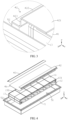
- the battery module M may include a box body 5 (the box body 5 shown in FIG. 2 is a structure with a top cover plate omitted), and the box body 5 includes an accommodation cavity 51.
- the accommodation cavity 51 is used to place battery cells 13 (see FIG. 4 ), and a plurality of battery cells 13 are stacked inside the accommodation cavity 51.
- the box body 5 is not limited to a specific type, and may be frame-shaped, disk-shaped, or box-shaped. Specifically, in the embodiment shown in FIG. 2 , the box body 5 may be a box body 5 with a rectangular structure.
- the battery module M includes one or more battery cell arrangement structures 1 (see FIG. 10 ).
- the battery cell arrangement structure 1 includes a plurality of battery cells 13 arranged along a length direction X, which means that in the battery cell arrangement structure 1, electrode terminals 131 of the battery cells 13 are arranged along the length direction X and face toward a width direction Y.
- the width direction Y refers to a width direction Y of the battery module M.
- the battery module M may include one battery cell arrangement structure 1, or may include two battery cell arrangement structures 1.
- electrode terminals 131 of battery cells 13 in the two battery cell arrangement structures 1 are facing away from each other, and bottoms of the two battery cell arrangement structures are close to each other.
- electrode terminals 131 of battery cells 13 in one battery cell arrangement structure 1 face toward one orientation of the width direction Y
- electrode terminals 131 of battery cells 13 in another battery cell arrangement structure 1 face toward the other orientation of the width direction Y
- the two battery cell arrangement structures 1 are close to or abut against each other along the width direction Y.
- the battery module M may include one layer of battery cell arrangement structure 1, or may include two layers of battery cell arrangement structures 1. Each layer may include two battery cell arrangement structures 1 arranged along the width direction Y.
- the battery module M includes two layers of battery cell arrangement structures 1, namely, a first battery cell arrangement structure 11 and a second battery cell arrangement structure 12 which are stacked along the height direction Z.
- each battery cell 13 includes a positive electrode terminal 131a and a negative electrode terminal 131b (see FIG. 9 ).
- a plurality of battery cells 13 are electrically connected to form a circuit of the battery module M.
- the battery cells 13 may be connected in series and/or parallel, and the battery cells 13 are connected by using adapting pieces (a first adapting piece 2 and a second adapting piece 3).
- the positive electrode terminal 131a of one battery cell 13 and the negative electrode terminal 131b of another battery cell 13 are connected by using an adapting piece.
- the battery cells 13 are continuously charged and discharged, and during the charging and discharging, the battery cells 13 are at a risk of failure (such as thermal runaway), causing a battery cell 13 unable to function properly.
- the battery cell 13 failed due to a failure that is the failed battery cell 133 (see FIG. 7 ), causes the circuit of the battery module M to fail and unable to supply power normally.
- the technical problem is resolved by short-circuiting the failed battery cell 133 to form a new circuit.
- the box body 5 of the battery module M further includes a mounting beam 52.
- the mounting beam 52 is located inside the accommodation cavity 51 of the box body 5, and at an end of the battery cell arrangement structure 1 along the width direction Y, which means that electrode terminals 131 of the battery cell arrangement structure 1 face toward the mounting beam 52.
- the battery module M further includes a pressing plate 4. At least part of the pressing plate 4 is located at an end of the battery cell arrangement structure 1 along the height direction Z, and the pressing plate 4 is detachably connected to the mounting beam 52. After the pressing plate 4 is connected to the mounting beam, the pressing plate 4 can be used to limit the battery cell arrangement structure 1 along the height direction Z, thereby improving stability of the battery cell arrangement structure 1 inside the accommodation cavity 51.
- the battery module M further includes a conductive component 6.
- the conductive component 6 is configured to directly or indirectly connect a positive electrode terminal 131a and a negative electrode terminal 131b of the failed battery cell 133.
- the conductive component 6 may be connected to the electrode terminals 131 of the failed battery cell 133 inside the failed battery cell 133, or may be connected to the electrode terminals 131 of the failed battery cell 133 outside the failed battery cell 133.
- the conductive component 6 may be directly connected to the electrode terminals 131 of the failed battery cell 133, or, when the electrode terminals 131 are connected to the adapting pieces, the conductive component 6 may be connected to the adapting pieces that are connected to the electrode terminals 131. Therefore, a short circuit between the positive electrode terminal 131a and the negative electrode terminal 131b of the failed battery cell 133 can be implemented by using the conductive component 6, so that the failed battery cell 133 is removed from the charge and discharge circuit of the battery module M.
- the battery cell 13 in the embodiments of this application may be a soft package battery, or may be a square battery or a cylindrical battery.
- the electrode terminals 131 (including the positive electrode terminal 131a and the negative electrode terminal 131b) of the battery cell 13 may be electrode terminals 131 the soft package battery, or may be electrode terminals 131 of the square battery or the cylindrical battery.
- the electrode terminal 131 may alternatively be a structure connected to the electrode pole and the adapting piece.
- the battery module M when one battery cell 13 or some battery cells 13 fail during operation of the battery module M, it is only required to connect the positive and negative electrode terminals 131 of the failed battery cell 133 by using the conductive component 6, without need to replace the entire battery module M.
- the battery module M when the battery module M is used in a vehicle, in case that one battery cell or some battery cells 13 fail, the vehicle can be repaired directly in a 4S shop, without need to return the vehicle to the factory for handling, or without need to replace the battery module M with a new battery module M, thereby improving maintenance efficiency and work efficiency (utilization) of the battery module M, simplifying a maintenance process, and reducing maintenance costs.
- a relatively small current goes through the failed battery cell 133, which may not cause a significant reduction of the battery capacity of the battery module M, so that the battery module M can function properly.
- the handling method of short-circuiting the failed battery cell 133 by using the conductive component 6 has the advantages of convenient operation and high efficiency.
- the conductive component 6 is located between the mounting beam 52 and an uppermost portion of the pressing plate 4, where the uppermost portion of the pressing plate 4 refers to a portion at which the pressing plate 4 has a highest height along the height direction (based on a same plane, for example, based on a bottom surface of the box body 5 of the battery module M).
- the pressing plate 4 includes a body part 41 and a connecting part 42, where the body part 41 is a flat plate structure (the height is the same everywhere), and the connecting part 42 may include a first connecting section 421, a second connecting section 422, and a transition section 423.
- the transition section 423 connects the first connecting section 421 and the second connecting section 422, the first connecting section 421 is connected to the body part 41, and the second connecting part 422 is connected to the mounting beam 52. Therefore, the first connecting section 421 is higher than the second connecting section 422 in height.
- the transition section 423 extends along the height direction Z, so that a cross section of the connecting part 42 is generally Z-shaped.
- the connecting part 42 with such a structure can facilitate to connecting the mounting beam 52 and the body part 41.
- the first connecting section 421 of the connecting part 42 overlaps on top of the body part 41.
- the uppermost portion of the pressing plate 4 is the first connecting section 421. Therefore, in this embodiment, along the height direction Z, at least part of the conductive component 6 is located between the second upper end surface 521 of the mounting beam 52 and the first connecting section 421 of the pressing plate 4, that is, located above the second upper end surface 521 (not necessarily in contact with the second upper end surface 521) and below the first connecting section 421 (not necessarily in contact with the first connecting section 421).
- connection may be no connection between the conductive component 6 and the mounting beam 52 and between the conductive component 6 and the pressing plate 4, or the conductive component 6 and the mounting beam 52 are connected and insulated by using another component, and the conductive component 6 and the first connecting section 421 are connected and insulated by using another component.
- the conductive component 6 when at least part of the conductive component 6 is located above the second upper end surface 521, the conductive component 6 is easily connected to or disconnected from electrode terminals 131 of the failed battery cell 133, which means that, there is no need to remove the mounting beam 52 and also no need to remove the battery cell arrangement structure 1 from the accommodation cavity 51, so that a maintenance process can be further simplified and maintenance costs can be reduced.
- the battery module M further include a first adapting piece 2 and a second adapting piece 3.
- the first adapting piece 2 and the second adapting piece 3 are connected to the electrode terminals 131 of the battery cells 13.
- the conductive component 6 is connected to the first adapting piece 2 and the second adapting piece 3 that are connected to the failed battery cell 133, which means that in this embodiment, the conductive component 6 can be connected to two electrode terminals 131 of the failed battery cell 133 indirectly.
- at least part of the first adapting piece 2 and part of the second adapting piece 3 are located between the mounting beam 52 and the uppermost portion of the pressing plate 4.
- the conductive component 6 can be easily connected to the first adapting piece 2 and the second adapting piece 3.
- a contact area between the conductive component 6 and an adapting piece is relatively large, so that a current flowing area between the two can be increased, and a risk of overheating at the connection locations can be reduced.
- a location for connecting the conductive component 6 and the first adapting piece 2 is between the mounting beam 52 and the pressing plate 4, and a location for connecting the conductive component 6 and the second adapting piece 3 is between the mounting beam 52 and an uppermost portion of the pressing plate 4.
- the location for connecting the conductive component 6 and the first adapting piece 2 and the location for connecting the conductive component 6 and the second adapting piece 3 are above the second upper end surface 521 of the mounting beam 52, so that the conductive component 6 can be easily connected to the first adapting piece 2 and the second adapting piece 3.
- the battery cell 13 includes a top cover plate 134, and the electrode terminals 131 are disposed on the top cover plate 134.
- the preset distance is used to provide an electrical gap between the electrode terminals 131 of the battery cells 13 and the mounting beam 52, thereby avoiding electrical connection between the battery cells 13 and the mounting beam 52 and ensuring that the battery module M can function properly.
- the pressing plate 4 when the pressing plate 4 is connected to the mounting beam 52, the box body 5, the mounting beam 52, and the pressing plate 4 enclose an accommodation space 53, and the conductive component 6 is located in the accommodation space 53. With the accommodation space 53, the conductive component 6 can be easily connected to the first adapting piece 2 and the second adapting piece 3.
- the conductive component 6 is connected to the electrode terminals 131.
- the conductive component 6 can be directly connected to the electrode terminals 131 of the failed battery cell 133.
- the positive electrode terminal 131a of the failed battery cell 133 is connected to the first adapting piece 2
- the negative electrode terminal 131b of the failed battery cell 133 is connected to the second adapting piece 3.
- the conductive component 6 when the conductive component 6 is directly connected to the positive electrode terminal 131a and the negative electrode terminal 131b, along the width direction Y, at least part of the conductive component 6 is located between the two adapting pieces and the top cover plate 134 of the failed battery cell 133, thereby capable of connecting to the positive electrode terminal 131a and the negative electrode terminal 131b.
- the failed battery cell 133 When the failed battery cell 133 is located in a lower battery cell arrangement structure 1, the failed battery cell 133 is located below the second upper end surface 521 of the mounting beam 52, and it is not easy to directly connect the conductive component 6 to the failed battery cell 133.
- the positive electrode terminal 131a of the failed battery cell 133 is connected to the first adapting piece 2
- the negative electrode terminal 131b of the failed battery cell 133 is connected to the second adapting piece 3.
- the first adapting piece 2 is also connected to a battery cell 11 located on the upper layer
- the second adapting piece 3 is also connected to a battery cell 11 located on the upper layer.
- the conductive component 6 can also be connected to the electrode terminal 131 that is located on the upper layer and connected to the first adapting piece 2 and the electrode terminal 131 that is located on the upper layer and connected to the second adapting piece 3, so as to indirectly connect the electrode terminals 131 of the failed battery cell 133.
- the conductive component 6 when the conductive component 6 is connected to the electrode terminals 131, they may be connected by welding. Certainly, they may alternatively be connected by another structure.
- the conductive component 6 includes two spaced matching slots 61 along a length direction X. A distance between the two matching slots 61 is equal to a distance between the two electrode terminals 131 connected to the conductive component 6.
- FIG. 14 when the conductive component 6 is connected to the positive electrode terminal 131a and the negative electrode terminal 131b of the failed battery cell 133, at least part of each of the two electrode terminals 131 is located in a corresponding matching slot 61, thereby connecting the conductive component 6 to the electrode terminals 131.
- the matching slot 61 includes a downward opening, and also includes a top wall 612 of the opening. Moreover, along the length direction X, the matching slot 61 includes two opposite side walls 611. When at least part of an electrode terminal 131 is located in the matching slot 61, the electrode terminal 131 abuts against the top wall 612, and the electrode terminal 131 also abuts against the two side walls 611, so that the electrode terminal 131 and the matching slot 61 are adapted to improve reliability of the connection between the conductive component 6 and the electrode terminal 131.
- the conductive component 6 may alternatively be welded to the corresponding electrode terminal 131, or may be electrically connected by a conductive adhesive.
- the pressing plate 4 may include a body part 41 and a connecting part 42.
- the body part 41 is located at an end of the battery cell arrangement structure 1 along the height direction Z.
- One end of the connecting part 42 is connected to the body part 41, and the other end of the connecting part 42 is detachably connected to the mounting beam 52, thereby connecting the pressing plate 4 to the mounting beam 52.
- the connecting part 42 of the pressing plate 4 and the mounting beam 52 may be directly connected, or a rubber pad may also be included between the two, which means that the connecting part 42 may be connected to the mounting beam 52 by using the rubber pad. Therefore, as the battery module M vibrates, the rubber pad can cushion the vibration between the connecting part 42 and the mounting beam 52, improving reliability of the connection between the pressing plate 4 and the mounting beam 52.
- the connecting part 42 of the pressing plate 4 when the connecting part 42 of the pressing plate 4 is detachably connected to the mounting beam 52, not only the pressing plate 4 can be mounted on the mounting beam 52 to improve stability of the battery cells 13 in the accommodation cavity 51, but also the connecting part 42 can be easily removed from the mounting beam 52. In this way, at least part of the first adapting piece 2 and part of the second adapting piece 3 can be exposed from the mounting beam 52, to allow connecting the conductive component 6 to the first adapting piece 2 and the second adapting piece 3.
- the connecting part 42 detachably connected to the mounting beam 52 can be easily removed, thereby facilitating to connect the conductive component 6 to the first adapting piece 2 and the second adapting piece 3.
- the battery cell 13 in the uppermost layer includes a first upper end surface 132, and the body part 41 is connected to the first upper end surface 132, where the two may be bonded by a structural adhesive, or connected by other means.
- the mounting beam 52 includes a second upper end surface 521, and the first upper end surface 132 is higher than the second upper end surface 521, that is, the first upper end surface 132 is located above the second upper end surface 521.
- the first connecting section 421 may be connected to the upper end surface of the body part 41 to increase a contact area between the two.
- the first connection section 421 may overlap the top of the body part 41.
- the first connection section 421 may be fixedly connected to the body part 41 by using screws, or the two may alternatively be connected by using a structural adhesive or by other means.
- the second connecting section 422 is detachably connected to the second upper end surface 521 of the mounting beam 52, and the two may specifically be fastened by using bolts.
- the connecting part 42 may further include a pressing block 424, and the pressing block 424 is connected to a lower portion of the first connecting section 421.
- the thickness of the pressing block 424 along the height direction Z is the same as the thickness of the body part 41.
- the pressing block 424 can abut against the first upper end surface 132 of the battery cell 13, that is, the first connecting section 421 is connected to the body part 41 and the first upper end surface 132.
- the second connecting section 422 is detachably connected to the second upper end surface 521 of the mounting beam 52. In this embodiment, connection reliability is high between the connecting part 42 and the battery cells 13 and between the connecting part 42 and the body part 41.
- the pressing plate 4 may include two connecting parts 42.
- the two connecting parts 42 are connected to two sides of the body part 41 along the width direction Y, so that the two sides of the pressing plate 4 along the width direction Y are connected to the mounting beam 52.
- the first connecting section 421 is overlapped with the body part 41, and an overlapped length of the two is 10 mm to 200 mm.
- the overlapped length may be 150 mm, 180 mm, or the like, and when the overlapped length of the two is long, connection reliability between the connecting part 42 and the body part 41 is high.
- the battery module M when along the width direction Y, the battery module M includes one battery cell arrangement structure 1, the body part 41 is within the battery cell arrangement structure 1 along the width direction Y, so that the body part 41 does not interfere with the conductive component 6 connecting to the first adapting piece 2 and the second adapting piece 3.
- the battery module M when along the width direction Y, the battery module M includes two battery cell arrangement structures 1, along the width direction Y, one end of the body part 41 is within one battery cell arrangement structure 11, and the other end of the body part 41 is within the other battery cell arrangement structure 12, which means that a width of the body part 41 is less that a sum of the widths of the two battery cell arrangement structures 1.
- the body part 41 even if the body part 41 is not removed from the pressing plate 4, the body part 41 does not interfere with the conductive component 6 connecting to the first adapting piece 2 and the second adapting piece 3.
- the battery module M includes at least two layers of battery cell arrangement structures 1, namely, the first battery cell arrangement structure 11 and the second battery cell arrangement structure 12, and along the height direction Z, the first battery cell arrangement structure 11 is located above the second battery cell arrangement structure 12.
- the first adapting piece 2 connects a battery cell 13 of the first battery cell arrangement structure 11 and a battery cell 13 of the second battery cell arrangement structure 12, and the second adapting piece 3 connects a battery cell 13 of the first battery cell arrangement structure 11 and a battery cell 13 of the second battery cell arrangement structure 12.
- battery cells 13 of the first battery cell arrangement structure 11 and battery cells 13 of the second battery cell arrangement structure 12 are connected in series by using the first adapting pieces 2 and the second adapting pieces 3, so that the first adapting pieces 2 and the second adapting pieces 3 are arranged obliquely along the height direction Z.
- the battery module M includes two layers of battery cell arrangement structures 1.
- the failed battery cell 133 located in the lower layer
- the conductive component 6 can also be connected by using the conductive component 6, so that the failed battery cell 133 can still be maintained without removing the battery cell arrangement structure 1.
- an embodiment of this application further provides a failure handling method for a failed battery cell 133.
- the failure handling method includes the following steps.
- S2 Electrically connect the positive electrode terminal 131a and the negative electrode terminal 131b of the failed battery cell 133 by using a conductive component 6, where the conductive component 6 may be directly connected to the positive electrode terminal 131a and the negative electrode terminal 131b, or may be indirectly connected to the positive electrode terminal 131a and the negative electrode terminal 131b (for example, by using a first adapting piece 2 and a second adapting piece 3).
- the conductive component 6 specifically may be a metal sheet or another structure, so as to implement a short circuit between the positive electrode terminal 131a and the negative electrode terminal 131b, and a cross-sectional area of the conductive component 6 should meet a current flowing requirement of the battery module M, thereby avoiding overheating at the conductive component 6.
- the pressing plate 4 may include the body part 41 and the connecting part 42 which are connected.
- the body part 41 is connected to a battery cell arrangement structure 1
- the connecting part 42 is connected to the mounting beam, and therefore, the above step S1 may specifically be: S11: Remove the connecting part 42 from the mounting beam 52.
- the connecting part 42 is detachably connected to the mounting beam 52 and the body part 41. In maintenance of a failed battery cell 133, there is no need to remove the entire pressing plate 4. At least part of the failed battery cell 133 can be exposed by only removing the connecting part 42, and therefore, the failed battery cell 133 can be easily maintained.
- step S2 may specifically be: S21: Electrically connect, by using the conductive component 6, the first adapting piece 2 and the second adapting piece 3 that are connected to the failed battery cell 133.
- two electrode terminals 131 of the failed battery cell 133 are indirectly connected by using the conductive component 6, so that the failed battery cell 133 is short-circuited.
- a contact area between the conductive component 6 and an adapting piece is relatively large, so that a current flowing area between the two can be increased, and a risk of overheating at the connection locations between the conductive component and the adapting pieces can be reduced.
- the conductive component 6 may be specifically connected to the two adapting pieces by welding, or may be connected by bonding, riveting and other means.
- the failure handling method may further include: S3: Mount the at least part of the pressing plate 4 that was removed from the mounting beam 52 back to the mounting beam 52.
- the step S3 specifically may be: S31: Mount the connecting part 42 that was removed from the mounting beam 52 back to the mounting beam 52.
- the battery cell arrangement structure(s) 1 may also be limited by the pressing plate 4 and the mounting beam 52.
Landscapes
- Chemical & Material Sciences (AREA)
- Chemical Kinetics & Catalysis (AREA)
- Electrochemistry (AREA)
- General Chemical & Material Sciences (AREA)
- Engineering & Computer Science (AREA)
- Manufacturing & Machinery (AREA)
- Mechanical Engineering (AREA)
- Transportation (AREA)
- Aviation & Aerospace Engineering (AREA)
- Combustion & Propulsion (AREA)
- Life Sciences & Earth Sciences (AREA)
- Sustainable Development (AREA)
- Sustainable Energy (AREA)
- Power Engineering (AREA)
- Battery Mounting, Suspending (AREA)
- Connection Of Batteries Or Terminals (AREA)
Description
- This application relates to the technical field of energy storage devices, and in particular, to a battery module, a device, and a failure handling method for a failed battery cell.
- A battery module includes a plurality of battery cells that are stacked, and the plurality of battery cells are electrically connected, to output electric energy of the battery module for supplying power to electrical appliances. There is a risk of failure when the battery cells are charged and discharged. The failure of one battery cell may cause the entire circuit of the battery module to fail, making the battery module unable to function properly. Currently, when a battery cell fails, usually the entire battery module is replaced. However, when one battery cell of the battery module fails, other battery cells can still function properly, so the method of directly replacing the entire battery module causes a waste of resources. In addition, it takes a long time to remove and install the battery module, which reduces work efficiency.
-
US2014127540A1 discloses a battery module, the battery module includes a plurality of battery packs teach being provided with an anode terminal and a cathode terminal; a plurality of coupling units each having ends coupled to the anode terminal and the cathode terminal of an adjacent battery pack, respectively, to couple the plurality of battery packs in series; an operation unit that is provided on one end of the coupling unit and ascends in accordance with an increasing internal pressure of the battery pack to open a coupling between the one end of the coupling unit and the terminals of the battery pack by raising the one end of the coupling unit; and a bypass unit having one end disposed over the one end of the coupling unit and the other end coupled to the other end of an adjacent coupling unit to maintain the other battery packs coupled in series, except for the battery packs the internal pressures of which have increased, when the one end of the coupling unit ascends by the operation unit. -
US2016218388A1 discloses a battery module having a minimized size. The battery module includes a secondary battery unit including a plurality of secondary batteries arranged with a predetermined interval in horizontal and vertical directions, a compression plate wrapping an exterior portion of the secondary battery unit and compressing the secondary battery unit with a predetermined pressure, and a housing accommodating the secondary battery unit combined with the compression plate, the housing including one or more bolt fastening units corresponding to portions between the plurality of secondary batteries arranged in the horizontal direction and protruding from a bottom surface of the housing and one or more bolts fastened with the one or more bolt fastening units by way of the portions between the plurality of secondary batteries arranged in the horizontal direction while passing through the compression plate. -
CN209447949U discloses a battery module which comprises a battery monomer arrangement structure, an upper cover and a lower cover, and the battery monomer arrangement structure is arranged between the upper cover and the lower cover; wherein each single battery comprises an electrode assembly and a battery shell, the electrode assembly is of a winding type structure and is flat, the outer surface of the electrode assembly comprises two flat surfaces, and the two flat surfaces face each other in the vertical direction; or the electrode assembly is of a laminated structure, and the first pole piece, the diaphragm and the second pole piece are laminated in the vertical direction. - The invention is set out in the appended set of claims.
-
-
FIG. 1 is a schematic structural diagram of a device according to a specific embodiment of this application; -
FIG. 2 is a schematic structural diagram of a battery module shown inFIG. 1 according to a specific embodiment, where a pressing plate is connected to a mounting beam; -
FIG. 3 is a locally enlarged view of part I inFIG. 2 ; -
FIG. 4 is an exploded view ofFIG. 2 ; -
FIG. 5 is a schematic structural diagram of the connecting part inFIG. 2 with the pressing plate removed; -
FIG. 6 is a schematic structural diagram of a first adapting piece and a second adapting piece connected by using a conductive component shown inFIG. 5 ; -
FIG. 7 is a locally enlarged view of part II inFIG. 6 ; -
FIG. 8 is an exploded view ofFIG. 2 , where a first adapting piece and a second adapting piece are connected by using a conductive component; -
FIG. 9 is a locally enlarged view of part III inFIG. 8 ; -
FIG. 10 is a sectional view ofFIG. 3 ; -
FIG. 11 is a locally enlarged view of part IV inFIG. 10 according to a first specific embodiment; -
FIG. 12 is a locally enlarged view of part IV inFIG. 10 according to a second specific embodiment; -
FIG. 13 is a schematic structural diagram of a battery cell arrangement structure in the battery module shown inFIG. 2 according to another specific embodiment; -
FIG. 14 is a locally enlarged view of part V inFIG. 13 ; -
FIG. 15 is a locally enlarged view of part VI inFIG. 13 ; and -
FIG. 16 is a schematic structural diagram of a conductive component. - Reference signs are described as follows:
- D. device;
- M. battery module;
- 1. battery cell arrangement structure;
- 11. first battery cell arrangement structure;
- 12. second battery cell arrangement structure;
- 13. battery cell;
- 131. electrode terminal;
- 131a. positive electrode terminal;
- 131b. negative electrode terminal;
- 132. first upper end surface;
- 133. failed battery cell;
- 134. top cover plate;
- 131. electrode terminal;
- 2. first adapting piece;
- 3. second adapting piece;
- 4. pressing plate;
- 41. body part;
- 42. connecting part;
- 421. first connecting section;
- 422. second connecting section;
- 423. transition section;
- 424. pressing block;
- 5. box body;
- 51. accommodation cavity;
- 52. mounting beam;
521. second upper end surface; - 53. accommodation space;
- 6. conductive component;
- 61. matching slot;
- 611. side wall; and
- 612. upper wall.
- 1. battery cell arrangement structure;
- The accompanying drawings herein are incorporated into this specification and form a part of this specification, illustrate the embodiments conforming to this application, and are intended to explain the principles of this application together with the specification.
- To help better understand the technical solutions of this application, the following describes the embodiments of this application with reference to accompanying drawings.
- An embodiment of this application provides a device D using
battery cells 13 as a power supply, and a battery module M. The device D usingbattery cells 13 as a power supply includes a vehicle, a ship, a small aircraft, and other mobile devices. The device D includes a power source, and the power source is configured to provide driving force for the device D, and the power source may be configured as the battery module M supplying electric energy to the device D. The driving force of the device D may be only electric energy, or may include electric energy and another energy source (such as mechanical energy). The power source may be a battery module M, or may be a battery module M and an engine. Therefore, any device D that can usebattery cells 13 as a power supply falls within the protection scope of this application. - As shown in
FIG. 1 , using a vehicle as an example, the device D in this embodiment of this application may be a new energy vehicle, which may be a battery electric vehicle, or may be a hybrid electric vehicle or an extended-range electric vehicle. The vehicle may include a battery module M and a vehicle body. The battery module M is disposed in the vehicle body. The vehicle body is also provided with a drive motor, and the drive motor is electrically connected to the battery module M. The battery module M provides electric energy to the drive motor. The drive motor is connected to wheels on the vehicle body through a transmission mechanism to drive travel of the vehicle. Specifically, the battery module M may be horizontally disposed at the bottom of the vehicle body. - As shown in
FIG. 2 , the battery module M may include a box body 5 (thebox body 5 shown inFIG. 2 is a structure with a top cover plate omitted), and thebox body 5 includes anaccommodation cavity 51. Theaccommodation cavity 51 is used to place battery cells 13 (seeFIG. 4 ), and a plurality ofbattery cells 13 are stacked inside theaccommodation cavity 51. Thebox body 5 is not limited to a specific type, and may be frame-shaped, disk-shaped, or box-shaped. Specifically, in the embodiment shown inFIG. 2 , thebox body 5 may be abox body 5 with a rectangular structure. - More specifically, as shown in
FIG. 4 , the battery module M includes one or more battery cell arrangement structures 1 (seeFIG. 10 ). The batterycell arrangement structure 1 includes a plurality ofbattery cells 13 arranged along a length direction X, which means that in the batterycell arrangement structure 1,electrode terminals 131 of thebattery cells 13 are arranged along the length direction X and face toward a width direction Y. The width direction Y refers to a width direction Y of the battery module M. Moreover, along the width direction Y, the battery module M may include one batterycell arrangement structure 1, or may include two batterycell arrangement structures 1. When the battery module M includes two batterycell arrangement structures 1,electrode terminals 131 ofbattery cells 13 in the two batterycell arrangement structures 1 are facing away from each other, and bottoms of the two battery cell arrangement structures are close to each other. To be specific,electrode terminals 131 ofbattery cells 13 in one batterycell arrangement structure 1 face toward one orientation of the width direction Y,electrode terminals 131 ofbattery cells 13 in another batterycell arrangement structure 1 face toward the other orientation of the width direction Y, and the two batterycell arrangement structures 1 are close to or abut against each other along the width direction Y. - Moreover, along a height direction Z, the battery module M may include one layer of battery
cell arrangement structure 1, or may include two layers of batterycell arrangement structures 1. Each layer may include two batterycell arrangement structures 1 arranged along the width direction Y. In the embodiment shown inFIG. 4 , the battery module M includes two layers of batterycell arrangement structures 1, namely, a first batterycell arrangement structure 11 and a second batterycell arrangement structure 12 which are stacked along the height direction Z. - Moreover, each
battery cell 13 includes a positive electrode terminal 131a and anegative electrode terminal 131b (seeFIG. 9 ). In the battery module M, a plurality ofbattery cells 13 are electrically connected to form a circuit of the battery module M. Specifically, thebattery cells 13 may be connected in series and/or parallel, and thebattery cells 13 are connected by using adapting pieces (afirst adapting piece 2 and a second adapting piece 3). For example, when thebattery cells 13 are connected in series, the positive electrode terminal 131a of onebattery cell 13 and thenegative electrode terminal 131b of anotherbattery cell 13 are connected by using an adapting piece. - During the operation of the battery module M, the
battery cells 13 are continuously charged and discharged, and during the charging and discharging, thebattery cells 13 are at a risk of failure (such as thermal runaway), causing abattery cell 13 unable to function properly. In this case, thebattery cell 13 failed due to a failure, that is the failed battery cell 133 (seeFIG. 7 ), causes the circuit of the battery module M to fail and unable to supply power normally. In this application, the technical problem is resolved by short-circuiting the failedbattery cell 133 to form a new circuit. - Specifically, as shown in
FIGs. 4 to 6 , thebox body 5 of the battery module M further includes a mountingbeam 52. The mountingbeam 52 is located inside theaccommodation cavity 51 of thebox body 5, and at an end of the batterycell arrangement structure 1 along the width direction Y, which means thatelectrode terminals 131 of the batterycell arrangement structure 1 face toward the mountingbeam 52. Moreover, the battery module M further includes apressing plate 4. At least part of thepressing plate 4 is located at an end of the batterycell arrangement structure 1 along the height direction Z, and thepressing plate 4 is detachably connected to the mountingbeam 52. After thepressing plate 4 is connected to the mounting beam, thepressing plate 4 can be used to limit the batterycell arrangement structure 1 along the height direction Z, thereby improving stability of the batterycell arrangement structure 1 inside theaccommodation cavity 51. - Moreover, the battery module M further includes a
conductive component 6. When abattery cell 13 has failed and a failedbattery cell 133 occurs, theconductive component 6 is configured to directly or indirectly connect a positive electrode terminal 131a and anegative electrode terminal 131b of the failedbattery cell 133. Theconductive component 6 may be connected to theelectrode terminals 131 of the failedbattery cell 133 inside the failedbattery cell 133, or may be connected to theelectrode terminals 131 of the failedbattery cell 133 outside the failedbattery cell 133. Theconductive component 6 may be directly connected to theelectrode terminals 131 of the failedbattery cell 133, or, when theelectrode terminals 131 are connected to the adapting pieces, theconductive component 6 may be connected to the adapting pieces that are connected to theelectrode terminals 131. Therefore, a short circuit between the positive electrode terminal 131a and thenegative electrode terminal 131b of the failedbattery cell 133 can be implemented by using theconductive component 6, so that the failedbattery cell 133 is removed from the charge and discharge circuit of the battery module M. - In addition, the
battery cell 13 in the embodiments of this application may be a soft package battery, or may be a square battery or a cylindrical battery. Accordingly, the electrode terminals 131 (including the positive electrode terminal 131a and thenegative electrode terminal 131b) of thebattery cell 13 may be electrodeterminals 131 the soft package battery, or may be electrodeterminals 131 of the square battery or the cylindrical battery. Moreover, when an electrode pole and a tab of thebattery cell 13 are connected by using an adapting piece, theelectrode terminal 131 may alternatively be a structure connected to the electrode pole and the adapting piece. - Therefore, when one
battery cell 13 or somebattery cells 13 fail during operation of the battery module M, it is only required to connect the positive andnegative electrode terminals 131 of the failedbattery cell 133 by using theconductive component 6, without need to replace the entire battery module M. When the battery module M is used in a vehicle, in case that one battery cell or somebattery cells 13 fail, the vehicle can be repaired directly in a 4S shop, without need to return the vehicle to the factory for handling, or without need to replace the battery module M with a new battery module M, thereby improving maintenance efficiency and work efficiency (utilization) of the battery module M, simplifying a maintenance process, and reducing maintenance costs. Moreover, after the foregoing handling, a relatively small current goes through the failedbattery cell 133, which may not cause a significant reduction of the battery capacity of the battery module M, so that the battery module M can function properly. - In addition, for a structure in which the
battery cell 13 is attached to theaccommodation cavity 51 of thebox body 5 through a structural adhesive, when aspecific battery cell 13 fails, it is not easy to implement an operation for removing the failedbattery cell 133 from theaccommodation cavity 51. Therefore, in this embodiment, the handling method of short-circuiting the failedbattery cell 133 by using theconductive component 6 has the advantages of convenient operation and high efficiency. - Moreover, for the battery module M shown in
FIG. 6 andFIG. 7 , along the height direction Z of the battery module M, at least part of theconductive component 6 is located between the mountingbeam 52 and an uppermost portion of thepressing plate 4, where the uppermost portion of thepressing plate 4 refers to a portion at which thepressing plate 4 has a highest height along the height direction (based on a same plane, for example, based on a bottom surface of thebox body 5 of the battery module M). - Using the embodiments shown in
FIG. 4 ,FIG. 11 and FIG. 12 as an example, thepressing plate 4 includes abody part 41 and a connectingpart 42, where thebody part 41 is a flat plate structure (the height is the same everywhere), and the connectingpart 42 may include a first connectingsection 421, a second connectingsection 422, and atransition section 423. Along the width direction Y, thetransition section 423 connects the first connectingsection 421 and the second connectingsection 422, the first connectingsection 421 is connected to thebody part 41, and the second connectingpart 422 is connected to the mountingbeam 52. Therefore, the first connectingsection 421 is higher than the second connectingsection 422 in height. Thetransition section 423 extends along the height direction Z, so that a cross section of the connectingpart 42 is generally Z-shaped. The connectingpart 42 with such a structure can facilitate to connecting the mountingbeam 52 and thebody part 41. - The first connecting
section 421 of the connectingpart 42 overlaps on top of thebody part 41. In this case, the uppermost portion of thepressing plate 4 is the first connectingsection 421. Therefore, in this embodiment, along the height direction Z, at least part of theconductive component 6 is located between the secondupper end surface 521 of the mountingbeam 52 and the first connectingsection 421 of thepressing plate 4, that is, located above the second upper end surface 521 (not necessarily in contact with the second upper end surface 521) and below the first connecting section 421 (not necessarily in contact with the first connecting section 421). There may be no connection between theconductive component 6 and the mountingbeam 52 and between theconductive component 6 and thepressing plate 4, or theconductive component 6 and the mountingbeam 52 are connected and insulated by using another component, and theconductive component 6 and the first connectingsection 421 are connected and insulated by using another component. - In this embodiment, when at least part of the
conductive component 6 is located above the secondupper end surface 521, theconductive component 6 is easily connected to or disconnected fromelectrode terminals 131 of the failedbattery cell 133, which means that, there is no need to remove the mountingbeam 52 and also no need to remove the batterycell arrangement structure 1 from theaccommodation cavity 51, so that a maintenance process can be further simplified and maintenance costs can be reduced. - Specifically, as shown in
FIG. 6 andFIG. 7 , the battery module M further include afirst adapting piece 2 and asecond adapting piece 3. Thefirst adapting piece 2 and thesecond adapting piece 3 are connected to theelectrode terminals 131 of thebattery cells 13. Theconductive component 6 is connected to thefirst adapting piece 2 and thesecond adapting piece 3 that are connected to the failedbattery cell 133, which means that in this embodiment, theconductive component 6 can be connected to twoelectrode terminals 131 of the failedbattery cell 133 indirectly. Moreover, after the connection done, along the height direction Z, at least part of thefirst adapting piece 2 and part of thesecond adapting piece 3 are located between the mountingbeam 52 and the uppermost portion of thepressing plate 4. - In this embodiment, for the
first adapting piece 2 and thesecond adapting piece 3 that are connected to theelectrode terminals 131 of the failedbattery cell 133, when at least part of thefirst adapting piece 2 and part of thesecond adapting piece 3 are located above the secondupper end surface 521 of the mountingbeam 52, theconductive component 6 can be easily connected to thefirst adapting piece 2 and thesecond adapting piece 3. Compared with the case where theconductive component 6 is directly connected to theelectrode terminals 131, when theconductive component 6 is connected to the adapting pieces, a contact area between theconductive component 6 and an adapting piece is relatively large, so that a current flowing area between the two can be increased, and a risk of overheating at the connection locations can be reduced. - More specifically, along the height direction Z, a location for connecting the
conductive component 6 and thefirst adapting piece 2 is between the mountingbeam 52 and thepressing plate 4, and a location for connecting theconductive component 6 and thesecond adapting piece 3 is between the mountingbeam 52 and an uppermost portion of thepressing plate 4. To be specific, the location for connecting theconductive component 6 and thefirst adapting piece 2 and the location for connecting theconductive component 6 and thesecond adapting piece 3 are above the secondupper end surface 521 of the mountingbeam 52, so that theconductive component 6 can be easily connected to thefirst adapting piece 2 and thesecond adapting piece 3. - As shown in
FIG. 9 ,FIG. 11, and FIG. 12 , thebattery cell 13 includes atop cover plate 134, and theelectrode terminals 131 are disposed on thetop cover plate 134. Along the width direction Y, there is a preset distance between thetop cover plate 134 and the mountingbeam 52, and the preset distance is used to provide an electrical gap between theelectrode terminals 131 of thebattery cells 13 and the mountingbeam 52, thereby avoiding electrical connection between thebattery cells 13 and the mountingbeam 52 and ensuring that the battery module M can function properly. - Moreover, when the
pressing plate 4 is connected to the mountingbeam 52, thebox body 5, the mountingbeam 52, and thepressing plate 4 enclose anaccommodation space 53, and theconductive component 6 is located in theaccommodation space 53. With theaccommodation space 53, theconductive component 6 can be easily connected to thefirst adapting piece 2 and thesecond adapting piece 3. - In another specific embodiment, as shown in
FIGs. 13 to 15 , theconductive component 6 is connected to theelectrode terminals 131. Specifically, when the failedbattery cell 133 is located in the uppermost batterycell arrangement structure 1, theconductive component 6 can be directly connected to theelectrode terminals 131 of the failedbattery cell 133. As shown inFIG. 14 , the positive electrode terminal 131a of the failedbattery cell 133 is connected to thefirst adapting piece 2, and thenegative electrode terminal 131b of the failedbattery cell 133 is connected to thesecond adapting piece 3. Therefore, when theconductive component 6 is directly connected to the positive electrode terminal 131a and thenegative electrode terminal 131b, along the width direction Y, at least part of theconductive component 6 is located between the two adapting pieces and thetop cover plate 134 of the failedbattery cell 133, thereby capable of connecting to the positive electrode terminal 131a and thenegative electrode terminal 131b. - When the failed
battery cell 133 is located in a lower batterycell arrangement structure 1, the failedbattery cell 133 is located below the secondupper end surface 521 of the mountingbeam 52, and it is not easy to directly connect theconductive component 6 to the failedbattery cell 133. The positive electrode terminal 131a of the failedbattery cell 133 is connected to thefirst adapting piece 2, thenegative electrode terminal 131b of the failedbattery cell 133 is connected to thesecond adapting piece 3. In addition, thefirst adapting piece 2 is also connected to abattery cell 11 located on the upper layer, thesecond adapting piece 3 is also connected to abattery cell 11 located on the upper layer. Therefore, theconductive component 6 can also be connected to theelectrode terminal 131 that is located on the upper layer and connected to thefirst adapting piece 2 and theelectrode terminal 131 that is located on the upper layer and connected to thesecond adapting piece 3, so as to indirectly connect theelectrode terminals 131 of the failedbattery cell 133. - Specifically, when the
conductive component 6 is connected to theelectrode terminals 131, they may be connected by welding. Certainly, they may alternatively be connected by another structure. For example, as shown inFIG. 16 , theconductive component 6 includes two spaced matching slots 61 along a length direction X. A distance between the two matching slots 61 is equal to a distance between the twoelectrode terminals 131 connected to theconductive component 6. UsingFIG. 14 as an example, when theconductive component 6 is connected to the positive electrode terminal 131a and thenegative electrode terminal 131b of the failedbattery cell 133, at least part of each of the twoelectrode terminals 131 is located in a corresponding matching slot 61, thereby connecting theconductive component 6 to theelectrode terminals 131. - More specifically, along the height direction Z, the matching slot 61 includes a downward opening, and also includes a
top wall 612 of the opening. Moreover, along the length direction X, the matching slot 61 includes twoopposite side walls 611. When at least part of anelectrode terminal 131 is located in the matching slot 61, theelectrode terminal 131 abuts against thetop wall 612, and theelectrode terminal 131 also abuts against the twoside walls 611, so that theelectrode terminal 131 and the matching slot 61 are adapted to improve reliability of the connection between theconductive component 6 and theelectrode terminal 131. - In addition, the
conductive component 6 may alternatively be welded to the correspondingelectrode terminal 131, or may be electrically connected by a conductive adhesive. - In a specific embodiment, as shown in
FIG. 3 andFIG. 11 , thepressing plate 4 may include abody part 41 and a connectingpart 42. Thebody part 41 is located at an end of the batterycell arrangement structure 1 along the height direction Z. One end of the connectingpart 42 is connected to thebody part 41, and the other end of the connectingpart 42 is detachably connected to the mountingbeam 52, thereby connecting thepressing plate 4 to the mountingbeam 52. - It should be noted that in this embodiment, along the height direction Z, the connecting
part 42 of thepressing plate 4 and the mountingbeam 52 may be directly connected, or a rubber pad may also be included between the two, which means that the connectingpart 42 may be connected to the mountingbeam 52 by using the rubber pad. Therefore, as the battery module M vibrates, the rubber pad can cushion the vibration between the connectingpart 42 and the mountingbeam 52, improving reliability of the connection between thepressing plate 4 and the mountingbeam 52. - In addition, when the connecting
part 42 of thepressing plate 4 is detachably connected to the mountingbeam 52, not only thepressing plate 4 can be mounted on the mountingbeam 52 to improve stability of thebattery cells 13 in theaccommodation cavity 51, but also the connectingpart 42 can be easily removed from the mountingbeam 52. In this way, at least part of thefirst adapting piece 2 and part of thesecond adapting piece 3 can be exposed from the mountingbeam 52, to allow connecting theconductive component 6 to thefirst adapting piece 2 and thesecond adapting piece 3. Moreover, when thebody part 41 of thepressing plate 4 is fixedly connected (for example, bonded) to thebattery cells 13, the connectingpart 42 detachably connected to the mountingbeam 52 can be easily removed, thereby facilitating to connect theconductive component 6 to thefirst adapting piece 2 and thesecond adapting piece 3. - Specifically, as shown in
FIG. 11 and FIG. 12 , along the height direction Z, thebattery cell 13 in the uppermost layer includes a firstupper end surface 132, and thebody part 41 is connected to the firstupper end surface 132, where the two may be bonded by a structural adhesive, or connected by other means. Moreover, along the height direction Z, the mountingbeam 52 includes a secondupper end surface 521, and the firstupper end surface 132 is higher than the secondupper end surface 521, that is, the firstupper end surface 132 is located above the secondupper end surface 521. - In the embodiment shown in
FIG. 11 , the first connectingsection 421 may be connected to the upper end surface of thebody part 41 to increase a contact area between the two. Thefirst connection section 421 may overlap the top of thebody part 41. Thefirst connection section 421 may be fixedly connected to thebody part 41 by using screws, or the two may alternatively be connected by using a structural adhesive or by other means. In addition, the second connectingsection 422 is detachably connected to the secondupper end surface 521 of the mountingbeam 52, and the two may specifically be fastened by using bolts. - In the embodiment shown in
FIG. 12 , the connectingpart 42 may further include apressing block 424, and thepressing block 424 is connected to a lower portion of the first connectingsection 421. The thickness of thepressing block 424 along the height direction Z is the same as the thickness of thebody part 41. When the first connectingsection 421 is overlapped with thebody part 41, thepressing block 424 can abut against the firstupper end surface 132 of thebattery cell 13, that is, the first connectingsection 421 is connected to thebody part 41 and the firstupper end surface 132. Moreover, the second connectingsection 422 is detachably connected to the secondupper end surface 521 of the mountingbeam 52. In this embodiment, connection reliability is high between the connectingpart 42 and thebattery cells 13 and between the connectingpart 42 and thebody part 41. - In the foregoing embodiments, the
pressing plate 4 may include two connectingparts 42. The two connectingparts 42 are connected to two sides of thebody part 41 along the width direction Y, so that the two sides of thepressing plate 4 along the width direction Y are connected to the mountingbeam 52. - The first connecting
section 421 is overlapped with thebody part 41, and an overlapped length of the two is 10 mm to 200 mm. For example, the overlapped length may be 150 mm, 180 mm, or the like, and when the overlapped length of the two is long, connection reliability between the connectingpart 42 and thebody part 41 is high. - Furthermore, when along the width direction Y, the battery module M includes one battery
cell arrangement structure 1, thebody part 41 is within the batterycell arrangement structure 1 along the width direction Y, so that thebody part 41 does not interfere with theconductive component 6 connecting to thefirst adapting piece 2 and thesecond adapting piece 3. Alternatively, in the embodiment shown inFIG. 10 , when along the width direction Y, the battery module M includes two batterycell arrangement structures 1, along the width direction Y, one end of thebody part 41 is within one batterycell arrangement structure 11, and the other end of thebody part 41 is within the other batterycell arrangement structure 12, which means that a width of thebody part 41 is less that a sum of the widths of the two batterycell arrangement structures 1. - In this embodiment, even if the
body part 41 is not removed from thepressing plate 4, thebody part 41 does not interfere with theconductive component 6 connecting to thefirst adapting piece 2 and thesecond adapting piece 3. - In addition, in the embodiments shown in
FIG. 8 andFIG. 9 , along the height direction Z, the battery module M includes at least two layers of batterycell arrangement structures 1, namely, the first batterycell arrangement structure 11 and the second batterycell arrangement structure 12, and along the height direction Z, the first batterycell arrangement structure 11 is located above the second batterycell arrangement structure 12. Thefirst adapting piece 2 connects abattery cell 13 of the first batterycell arrangement structure 11 and abattery cell 13 of the second batterycell arrangement structure 12, and thesecond adapting piece 3 connects abattery cell 13 of the first batterycell arrangement structure 11 and abattery cell 13 of the second batterycell arrangement structure 12. To be specific,battery cells 13 of the first batterycell arrangement structure 11 andbattery cells 13 of the second batterycell arrangement structure 12 are connected in series by using thefirst adapting pieces 2 and thesecond adapting pieces 3, so that thefirst adapting pieces 2 and thesecond adapting pieces 3 are arranged obliquely along the height direction Z. - In this embodiment, in this connection manner, for the
first adapting piece 2 and thesecond adapting piece 3 that are connected to thebattery cells 13 of the second batterycell arrangement structure 12 in the lower layer, at least part of thefirst adapting piece 2 and part of thesecond adapting piece 3 are located above the secondupper end surface 521 of the mountingbeam 52, so that thefirst adapting piece 2 and thesecond adapting piece 3 can be connected by using theconductive component 6. To be specific, in this connection manner, the battery module M includes two layers of batterycell arrangement structures 1. When abattery cell 13 of the second batterycell arrangement structure 12 in the lower layer fails, the failed battery cell 133 (located in the lower layer) can also be connected by using theconductive component 6, so that the failedbattery cell 133 can still be maintained without removing the batterycell arrangement structure 1. - In addition, an embodiment of this application further provides a failure handling method for a failed
battery cell 133. The failure handling method includes the following steps. - S1: Remove at least part of a
pressing plate 4 from the mountingbeam 52. - In this step, after at least part of the
pressing plate 4 is removed, at least part of the failedbattery cell 131 is exposed, which can facilitate to accordingly perform an operation on the failedbattery cell 133. - S2: Electrically connect the positive electrode terminal 131a and the
negative electrode terminal 131b of the failedbattery cell 133 by using aconductive component 6, where theconductive component 6 may be directly connected to the positive electrode terminal 131a and thenegative electrode terminal 131b, or may be indirectly connected to the positive electrode terminal 131a and thenegative electrode terminal 131b (for example, by using afirst adapting piece 2 and a second adapting piece 3). - The
conductive component 6 specifically may be a metal sheet or another structure, so as to implement a short circuit between the positive electrode terminal 131a and thenegative electrode terminal 131b, and a cross-sectional area of theconductive component 6 should meet a current flowing requirement of the battery module M, thereby avoiding overheating at theconductive component 6. - Specifically, as described above, the
pressing plate 4 may include thebody part 41 and the connectingpart 42 which are connected. In thepressing plate 4, thebody part 41 is connected to a batterycell arrangement structure 1, the connectingpart 42 is connected to the mounting beam, and therefore, the above step S1 may specifically be:
S11: Remove the connectingpart 42 from the mountingbeam 52. - In this embodiment, the connecting
part 42 is detachably connected to the mountingbeam 52 and thebody part 41. In maintenance of a failedbattery cell 133, there is no need to remove the entirepressing plate 4. At least part of the failedbattery cell 133 can be exposed by only removing the connectingpart 42, and therefore, the failedbattery cell 133 can be easily maintained. - More specifically, two
electrode terminals 131 of the failedbattery cell 133 are connected to thefirst adapting piece 2 and thesecond adapting piece 3 respectively, and therefore, the above step S2 may specifically be:
S21: Electrically connect, by using theconductive component 6, thefirst adapting piece 2 and thesecond adapting piece 3 that are connected to the failedbattery cell 133. - In this embodiment, two
electrode terminals 131 of the failedbattery cell 133 are indirectly connected by using theconductive component 6, so that the failedbattery cell 133 is short-circuited. In addition, when theconductive component 6 is connected to the two adapting pieces, a contact area between theconductive component 6 and an adapting piece is relatively large, so that a current flowing area between the two can be increased, and a risk of overheating at the connection locations between the conductive component and the adapting pieces can be reduced. - In addition, the
conductive component 6 may be specifically connected to the two adapting pieces by welding, or may be connected by bonding, riveting and other means. - More specifically, after the step S2, the failure handling method may further include:
S3: Mount the at least part of thepressing plate 4 that was removed from the mountingbeam 52 back to the mountingbeam 52. - When the at least part of the
pressing plate 4 that was removed from the mountingbeam 52 in the step S1 is the connectingpart 42, the step S3 specifically may be:
S31: Mount the connectingpart 42 that was removed from the mountingbeam 52 back to the mountingbeam 52. - In this step, after the removed connecting
part 42 is re-mounted to the mountingbeam 52, the maintenance of the failedbattery cell 133 is completed. In the battery module M, the battery cell arrangement structure(s) 1 may also be limited by thepressing plate 4 and the mountingbeam 52. - When the failed
battery cell 133 is located in a lower batterycell arrangement structure 1, the failedbattery cell 133 is located below the secondupper end surface 521 of the mountingbeam 52, and it is not easy to directly connect theconductive component 6 to the failedbattery cell 133. The positive electrode terminal 131a of the failedbattery cell 133 is connected to thefirst adapting piece 2, thenegative electrode terminal 131b of the failedbattery cell 133 is connected to thesecond adapting piece 3. In addition, thefirst adapting piece 2 is also connected to abattery cell 11 located on the upper layer, thesecond adapting piece 3 is also connected to abattery cell 11 located on the upper layer. Therefore, theconductive component 6 can also be connected to theelectrode terminal 131 that is located on the upper layer and connected to thefirst adapting piece 2 and theelectrode terminal 131 that is located on the upper layer and connected to thesecond adapting piece 3, so as to indirectly connect theelectrode terminals 131 of the failedbattery cell 133. - Specifically, when the
conductive component 6 is connected to theelectrode terminals 131, they may be connected by welding. Certainly, they may alternatively be connected by another structure. For example, as shown inFIG. 16 , theconductive component 6 includes two spaced matching slots 61 along a length direction X. A distance between the two matching slots 61 is equal to a distance between the twoelectrode terminals 131 connected to theconductive component 6. UsingFIG. 14 as an example, when theconductive component 6 is connected to the positive electrode terminal 131a and thenegative electrode terminal 131b of the failedbattery cell 133, at least part of each of the twoelectrode terminals 131 is located in a corresponding matching slot 61, thereby connecting theconductive component 6 to theelectrode terminals 131. - More specifically, along the height direction Z, the matching slot 61 includes a downward opening, and also includes a
top wall 612 of the opening. Moreover, along the length direction X, the matching slot 61 includes twoopposite side walls 611. When at least part of anelectrode terminal 131 is located in the matching slot 61, theelectrode terminal 131 abuts against thetop wall 612, and theelectrode terminal 131 also abuts against the twoside walls 611, so that theelectrode terminal 131 and the matching slot 61 are adapted to improve reliability of the connection between theconductive component 6 and theelectrode terminal 131. - In addition, the
conductive component 6 may alternatively be welded to the correspondingelectrode terminal 131, or may be electrically connected by a conductive adhesive. - In a specific embodiment, as shown in
FIG. 3 andFIG. 11 , thepressing plate 4 may include abody part 41 and a connectingpart 42. Thebody part 41 is located at an end of the batterycell arrangement structure 1 along the height direction Z. One end of the connectingpart 42 is connected to thebody part 41, and the other end of the connectingpart 42 is detachably connected to the mountingbeam 52, thereby connecting thepressing plate 4 to the mountingbeam 52. - It should be noted that in this embodiment, along the height direction Z, the connecting
part 42 of thepressing plate 4 and the mountingbeam 52 may be directly connected, or a rubber pad may also be included between the two, which means that the connectingpart 42 may be connected to the mountingbeam 52 by using the rubber pad. Therefore, as the battery module M vibrates, the rubber pad can cushion the vibration between the connectingpart 42 and the mountingbeam 52, improving reliability of the connection between thepressing plate 4 and the mountingbeam 52. - In addition, when the connecting
part 42 of thepressing plate 4 is detachably connected to the mountingbeam 52, not only thepressing plate 4 can be mounted on the mountingbeam 52 to improve stability of thebattery cells 13 in theaccommodation cavity 51, but also the connectingpart 42 can be easily removed from the mountingbeam 52. In this way, at least part of thefirst adapting piece 2 and part of thesecond adapting piece 3 can be exposed from the mountingbeam 52, to allow connecting theconductive component 6 to thefirst adapting piece 2 and thesecond adapting piece 3. Moreover, when thebody part 41 of thepressing plate 4 is fixedly connected (for example, bonded) to thebattery cells 13, the connectingpart 42 detachably connected to the mountingbeam 52 can be easily removed, thereby facilitating to connect theconductive component 6 to thefirst adapting piece 2 and thesecond adapting piece 3. - Specifically, as shown in
FIG. 11 and FIG. 12 , along the height direction Z, thebattery cell 13 in the uppermost layer includes a firstupper end surface 132, and thebody part 41 is connected to the firstupper end surface 132, where the two may be bonded by a structural adhesive, or connected by other means. Moreover, along the height direction Z, the mountingbeam 52 includes a secondupper end surface 521, and the firstupper end surface 132 is higher than the secondupper end surface 521, that is, the firstupper end surface 132 is located above the secondupper end surface 521. - In the embodiment shown in
FIG. 11 , the first connectingsection 421 may be connected to the upper end surface of thebody part 41 to increase a contact area between the two. Thefirst connection section 421 may overlap the top of thebody part 41. Thefirst connection section 421 may be fixedly connected to thebody part 41 by using screws, or the two may alternatively be connected by using a structural adhesive or by other means. In addition, the second connectingsection 422 is detachably connected to the secondupper end surface 521 of the mountingbeam 52, and the two may specifically be fastened by using bolts. - In the embodiment shown in
FIG. 12 , the connectingpart 42 may further include apressing block 424, and thepressing block 424 is connected to a lower portion of the first connectingsection 421. The thickness of thepressing block 424 along the height direction Z is the same as the thickness of thebody part 41. When the first connectingsection 421 is overlapped with thebody part 41, thepressing block 424 can abut against the firstupper end surface 132 of thebattery cell 13, that is, the first connectingsection 421 is connected to thebody part 41 and the firstupper end surface 132. Moreover, the second connectingsection 422 is detachably connected to the secondupper end surface 521 of the mountingbeam 52. In this embodiment, connection reliability is high between the connectingpart 42 and thebattery cells 13 and between the connectingpart 42 and thebody part 41. - In the foregoing embodiments, the
pressing plate 4 may include two connectingparts 42. The two connectingparts 42 are connected to two sides of thebody part 41 along the width direction Y, so that the two sides of thepressing plate 4 along the width direction Y are connected to the mountingbeam 52. - The first connecting
section 421 is overlapped with thebody part 41, and an overlapped length of the two is 10 mm to 200 mm. For example, the overlapped length may be 150 mm, 180 mm, or the like, and when the overlapped length of the two is long, connection reliability between the connectingpart 42 and thebody part 41 is high. - Furthermore, when along the width direction Y, the battery module M includes one battery
cell arrangement structure 1, thebody part 41 is within the batterycell arrangement structure 1 along the width direction Y, so that thebody part 41 does not interfere with theconductive component 6 connecting to thefirst adapting piece 2 and thesecond adapting piece 3. Alternatively, in the embodiment shown inFIG. 10 , when along the width direction Y, the battery module M includes two batterycell arrangement structures 1, along the width direction Y, one end of thebody part 41 is within one batterycell arrangement structure 11, and the other end of thebody part 41 is within the other batterycell arrangement structure 12, which means that a width of thebody part 41 is less that a sum of the widths of the two batterycell arrangement structures 1. - In this embodiment, even if the
body part 41 is not removed from thepressing plate 4, thebody part 41 does not interfere with theconductive component 6 connecting to thefirst adapting piece 2 and thesecond adapting piece 3. - In addition, in the embodiments shown in
FIG. 8 andFIG. 9 , along the height direction Z, the battery module M includes at least two layers of batterycell arrangement structures 1, namely, the first batterycell arrangement structure 11 and the second batterycell arrangement structure 12, and along the height direction Z, the first batterycell arrangement structure 11 is located above the second batterycell arrangement structure 12. Thefirst adapting piece 2 connects abattery cell 13 of the first batterycell arrangement structure 11 and abattery cell 13 of the second batterycell arrangement structure 12, and thesecond adapting piece 3 connects abattery cell 13 of the first batterycell arrangement structure 11 and abattery cell 13 of the second batterycell arrangement structure 12. To be specific,battery cells 13 of the first batterycell arrangement structure 11 andbattery cells 13 of the second batterycell arrangement structure 12 are connected in series by using thefirst adapting pieces 2 and thesecond adapting pieces 3, so that thefirst adapting pieces 2 and thesecond adapting pieces 3 are arranged obliquely along the height direction Z. - In this embodiment, in this connection manner, for the
first adapting piece 2 and thesecond adapting piece 3 that are connected to thebattery cells 13 of the second batterycell arrangement structure 12 in the lower layer, at least part of thefirst adapting piece 2 and part of thesecond adapting piece 3 are located above the secondupper end surface 521 of the mountingbeam 52, so that thefirst adapting piece 2 and thesecond adapting piece 3 can be connected by using theconductive component 6. To be specific, in this connection manner, the battery module M includes two layers of batterycell arrangement structures 1. When abattery cell 13 of the second batterycell arrangement structure 12 in the lower layer fails, the failed battery cell 133 (located in the lower layer) can also be connected by using theconductive component 6, so that the failedbattery cell 133 can still be maintained without removing the batterycell arrangement structure 1. - In addition, an embodiment of this application further provides a failure handling method for a failed
battery cell 133. The failure handling method includes the following steps. - S1: Remove at least part of a
pressing plate 4 from the mountingbeam 52. - In this step, after at least part of the
pressing plate 4 is removed, at least part of the failedbattery cell 131 is exposed, which can facilitate to accordingly perform an operation on the failedbattery cell 133. - S2: Electrically connect the positive electrode terminal 131a and the
negative electrode terminal 131b of the failedbattery cell 133 by using aconductive component 6, where theconductive component 6 may be directly connected to the positive electrode terminal 131a and thenegative electrode terminal 131b, or may be indirectly connected to the positive electrode terminal 131a and thenegative electrode terminal 131b (for example, by using afirst adapting piece 2 and a second adapting piece 3). - The
conductive component 6 specifically may be a metal sheet or another structure, so as to implement a short circuit between the positive electrode terminal 131a and thenegative electrode terminal 131b, and a cross-sectional area of theconductive component 6 should meet a current flowing requirement of the battery module M, thereby avoiding overheating at theconductive component 6. - Specifically, as described above, the
pressing plate 4 may include thebody part 41 and the connectingpart 42 which are connected. In thepressing plate 4, thebody part 41 is connected to a batterycell arrangement structure 1, the connectingpart 42 is connected to the mounting beam, and therefore, the above step S1 may specifically be:
S11: Remove the connectingpart 42 from the mountingbeam 52. - In this embodiment, the connecting
part 42 is detachably connected to the mountingbeam 52 and thebody part 41. In maintenance of a failedbattery cell 133, there is no need to remove the entirepressing plate 4. At least part of the failedbattery cell 133 can be exposed by only removing the connectingpart 42, and therefore, the failedbattery cell 133 can be easily maintained. - More specifically, two
electrode terminals 131 of the failedbattery cell 133 are connected to thefirst adapting piece 2 and thesecond adapting piece 3 respectively, and therefore, the above step S2 may specifically be:
S21: Electrically connect, by using theconductive component 6, thefirst adapting piece 2 and thesecond adapting piece 3 that are connected to the failedbattery cell 133. - In this embodiment, two
electrode terminals 131 of the failedbattery cell 133 are indirectly connected by using theconductive component 6, so that the failedbattery cell 133 is short-circuited. In addition, when theconductive component 6 is connected to the two adapting pieces, a contact area between theconductive component 6 and an adapting piece is relatively large, so that a current flowing area between the two can be increased, and a risk of overheating at the connection locations between the conductive component and the adapting pieces can be reduced. - In addition, the
conductive component 6 may be specifically connected to the two adapting pieces by welding, or may be connected by bonding, riveting and other means. - More specifically, after the step S2, the failure handling method may further include:
S3: Mount the at least part of thepressing plate 4 that was removed from the mountingbeam 52 back to the mountingbeam 52. - When the at least part of the
pressing plate 4 that was removed from the mountingbeam 52 in the step S1 is the connectingpart 42, the step S3 specifically may be:
S31: Mount the connectingpart 42 that was removed from the mountingbeam 52 back to the mountingbeam 52. - In this step, after the removed connecting
part 42 is re-mounted to the mountingbeam 52, the maintenance of the failedbattery cell 133 is completed. In the battery module M, the battery cell arrangement structure(s) 1 may also be limited by thepressing plate 4 and the mountingbeam 52.
Claims (14)
- A battery module (M), wherein the battery module (M) comprises:
a battery cell arrangement structure (1), comprising a plurality of battery cells (13) arranged along a length direction (X) of the battery module (M), wherein the battery cells (13) comprise electrode terminals (131) that are arranged along the length direction (X), and face toward a width direction (Y) of the battery module (M), and the battery cells (13) comprise a failed battery cell (133); characterized in that, the battery module (M) further comprises:a box body (5), wherein the box body (5) comprises an accommodation cavity (51), and the battery cell arrangement structure (1) is located in the accommodation cavity (51);a mounting beam (52), wherein the mounting beam (52) is located in the accommodation cavity (51) and at an end of the battery cell arrangement structure (1) along the width direction (Y), and along a height direction (Z) of the battery module (M), the mounting beam (52) comprises a second upper end surface (521);a pressing plate (4), wherein at least part of the pressing plate (4) is located at an end of the battery cell arrangement structure (1) along the height direction (Z), and the pressing plate (4) is detachably connected to the mounting beam (52); anda conductive component (6), wherein the conductive component (6) is connected to a positive electrode terminal (131a) and a negative electrode terminal (131b) of the failed battery cell (133);wherein, along the height direction (Z), at least part of the conductive component (6) is located between the second upper end surface (521) and an uppermost portion of the pressing plate (4). - The battery module (M) according to claim 1, wherein the pressing plate (4) comprises a body part (41) and a connecting part (42), and the body part (41) is located at an end of the battery cell arrangement structure (1) along the height direction (Z); and
one end of the connecting part (42) is connected to the body part (41), and the other end of the connecting part (42) is detachably connected to the mounting beam (52). - The battery module (M) according to claim 2, wherein along the height direction (Z), the battery cell (13) on the uppermost layer comprises a first upper end surface (132), and the body part (41) is connected to the first upper end surface (132);the first upper end surface (132) is higher than the second upper end surface (521);the connecting part (42) comprises a first connecting section (421), a second connecting section (422) and a transition section (423), and the transition section (423) connects the first connecting section (421) and the second connecting section (422);the first connecting section (421) is connected to the body part (41), or the first connecting section (421) is connected to the body part (41) and the first upper end surface (132); andthe second connecting section (422) is detachably connected to the second upper end surface (521).
- The battery module (M) according to any one of claims 1 to 3, wherein the battery cell (13) comprises a top cover plate (134), and the electrode terminals (131) are disposed on the top cover plate (134);along the width direction (Y), there is a preset distance between the top cover plate (134) and the mounting beam (52); andwhen the pressing plate (4) is connected to the mounting beam (52), the box body (5), the mounting beam (52), and the pressing plate (4) enclose an accommodation space (53), and the conductive component (6) is located in the accommodation space (53).
- The battery module (M) according to claim 3, wherein the body part (41) is bonded to the first upper end surface (132); and
the first connecting section (421) is overlapped with the body part (41), and an overlapped length of the two is 10 mm to 200 mm. - The battery module (M) according to claim 2 or 3, wherein along the width direction (Y), the battery module (M) comprises one battery cell arrangement structure (1), and along the width direction (Y), the body part (41) is within the battery cell arrangement structure (1); or
along the width direction (Y), the battery module (M) comprises two battery cell arrangement structures (1), electrode terminals (131) of the two battery cell arrangement structures (1) are facing away from each other, and along the width direction (Y), one end of the body part (41) is within one battery cell arrangement structure (1), and the other end of the body part (41) is within the other battery cell arrangement structure (1). - The battery module (M) according to any one of claims 1 to 6, wherein the battery module (M) further comprises a first adapting piece (2) and a second adapting piece (3), and the first adapting piece (2) and the second adapting piece (3) are connected to the electrode terminals (131) of the battery cells (13);the conductive component (6) is connected to the first adapting piece (2) and the second adapting piece (3) that are connected to the failed battery cell (133); andalong the height direction (Z), at least part of the first adapting piece (2) and part of the second adapting piece (3) are located between the second upper end surface (521) and the uppermost portion of the pressing plate (4).
- The battery module (M) according to any one of claims 1 to 7, wherein along the height direction (Z), a location for connecting the conductive component (6) and the first adapting piece (2) is between the second upper end surface (521) and the pressing plate (4), and a location for connecting the conductive component (6) and the second adapting piece (3) is between the second upper end surface (521) and the uppermost portion of the pressing plate (4).
- The battery module (M) according to any one of claims 1 to 8, wherein the battery cell arrangement structure (1) comprises a first battery cell arrangement structure (11) and a second battery cell arrangement structure (12), and along the height direction (Z), the first battery cell arrangement structure (11) is located above the second battery cell arrangement structure (12); and
the first adapting piece (2) connects a battery cell (13) of the first battery cell arrangement structure (11) and a battery cell (13) of the second battery cell arrangement structure (12), and the second adapting piece (3) connects a battery cell (13) of the first battery cell arrangement structure (11) and a battery cell (13) of the second battery cell arrangement structure (12). - A device (D), comprising battery cells (13) as a power supply, wherein the apparatus (D) comprises:a power source, the power source being configured to provide driving force for the apparatus (D); and,the battery module (M) according to any one of claims 1 to 9, configured to supply electric energy to the power source.
- A failure handling method for a failed battery cell (133), wherein a battery cell arrangement structure (1) comprises a plurality of battery cells (13), the battery cells (13) comprise a failed battery cell (133), the failed battery cell (133) comprises a positive electrode terminal (131a) and a negative electrode terminal (131b), a mounting beam (52) is provided at an end of the battery cell arrangement structure (1) along a width direction (Y), and a pressing plate (4) is provided at an end of the battery cell arrangement structure (1) along a height direction (Z);
a battery module (M) comprises:the battery cell arrangement structure (1);a box body (5), wherein the box body (5) comprises an accommodation cavity (51), and the battery cell arrangement structure (1) is located in the accommodation cavity (51);wherein the mounting beam (52), wherein the mounting beam (52) is located in the accommodation cavity (51) and at an end of the battery cell arrangement structure (1) along the width direction (Y), and along a height direction (Z) of the battery module (M), the mounting beam (52) comprises a second upper end surface (521);wherein the pressing plate (4) is detachably connected to the mounting beam (52); andalong the height direction (Z), at least part of a conductive component (6) is located between the second upper end surface (521) and an uppermost portion of the pressing plate (4);the failure handling method comprises:removing at least part of the pressing plate (4) from the mounting beam (52); andelectrically connecting a positive electrode terminal (131a) and a negative electrode terminal (131b) of the failed battery cell (133) by the conductive component (6). - The failure handling method according to claim 11, wherein the pressing plate (4) comprises a body part (41) and a connecting part (42), and when at least part of the pressing plate (4) is to be removed from the mounting beam (52), the failure handling method comprises:
removing the connecting part (42) from the mounting beam (52). - The failure handling method according to claim 11 or 12, wherein two electrode terminals (131) of the failed battery cell (133) are connected to a first adapting piece (2) and a second adapting piece (3) respectively, and when the positive electrode terminal (131a) and the negative electrode terminal (131b) of the failed battery cell (133) are to be connected by the conductive component (6), the failure handling method comprises:
electrically connecting, by the conductive component (6), the first adapting piece (2) and the second adapting piece (3) that are connected to the failed battery cell (133). - The failure handling method according to any one of claims 11 to 13, wherein after the positive electrode terminal (131a) and the negative electrode terminal (131b) of the failed battery cell (133) are electrically connected by the conductive component (6), the failure handling method further comprises:
mounting the at least part of the pressing plate (4) that was removed from the mounting beam (52) back to the mounting beam (52).
Applications Claiming Priority (2)
| Application Number | Priority Date | Filing Date | Title |
|---|---|---|---|
| CN201911205489.5A CN112331983B (en) | 2019-11-29 | 2019-11-29 | Battery module, device and failure treatment method for failed battery cells |
| PCT/CN2020/131573 WO2021104332A1 (en) | 2019-11-29 | 2020-11-25 | Battery module, device, and failure treatment method for failed battery cell |
Publications (4)
| Publication Number | Publication Date |
|---|---|
| EP3930083A1 EP3930083A1 (en) | 2021-12-29 |
| EP3930083A4 EP3930083A4 (en) | 2022-06-08 |
| EP3930083B1 true EP3930083B1 (en) | 2024-09-04 |
| EP3930083C0 EP3930083C0 (en) | 2024-09-04 |
Family
ID=74319765
Family Applications (1)
| Application Number | Title | Priority Date | Filing Date |
|---|---|---|---|
| EP20892646.9A Active EP3930083B1 (en) | 2019-11-29 | 2020-11-25 | Battery module, device, and failure treatment method for failed battery cell |
Country Status (7)
| Country | Link |
|---|---|
| US (2) | US11588186B2 (en) |
| EP (1) | EP3930083B1 (en) |
| JP (1) | JP7256335B2 (en) |
| KR (1) | KR102517184B1 (en) |
| CN (1) | CN112331983B (en) |
| HU (1) | HUE069124T2 (en) |
| WO (1) | WO2021104332A1 (en) |
Families Citing this family (4)
| Publication number | Priority date | Publication date | Assignee | Title |
|---|---|---|---|---|
| CN112310492B (en) * | 2019-11-29 | 2021-08-20 | 宁德时代新能源科技股份有限公司 | Battery module, device and failure treatment method for failed battery cells |
| CN112331983B (en) * | 2019-11-29 | 2021-10-08 | 宁德时代新能源科技股份有限公司 | Battery module, device and failure treatment method for failed battery cells |
| KR102819724B1 (en) | 2020-04-03 | 2025-06-12 | 컨템포러리 엠퍼렉스 테크놀로지 (홍콩) 리미티드 | Battery modules, battery packs, devices and fault handling methods |
| DE102023002338A1 (en) * | 2023-06-09 | 2024-12-12 | Mercedes-Benz Group AG | Method for repairing a battery cell assembly and battery cell assembly |
Family Cites Families (35)
| Publication number | Priority date | Publication date | Assignee | Title |
|---|---|---|---|---|
| FR2125768A5 (en) * | 1971-02-19 | 1972-09-29 | Accumulateurs Fixes | |
| JP2000133318A (en) * | 1998-08-21 | 2000-05-12 | Sony Corp | Battery pack |
| JP2003132873A (en) * | 2001-10-26 | 2003-05-09 | Mitsubishi Electric Corp | Battery pack using secondary battery |
| CN1172384C (en) * | 2002-03-23 | 2004-10-20 | 孙康 | Battery shifter |
| JP2005283516A (en) * | 2004-03-30 | 2005-10-13 | Fujio Kurokawa | Secondary battery monitoring system |
| FR2888669B1 (en) * | 2005-07-13 | 2010-08-20 | Batscap Sa | INTERCONNECTION SYSTEM FOR AN ENERGY STORAGE ASSEMBLY |
| JP2008034183A (en) * | 2006-07-27 | 2008-02-14 | Mazda Motor Corp | Battery cell bypass structure of the battery |
| JP2008192551A (en) * | 2007-02-07 | 2008-08-21 | Toyota Motor Corp | Battery pack structure |
| DE102007017018A1 (en) * | 2007-04-11 | 2008-03-27 | Daimler Ag | Battery e.g. lithium ion battery, for fuel cell-vehicle, has bypass device designed such that contact unit is switched to switching condition, in which defective cell is by-passed for maintaining current path of battery, if cell is failed |
| CN101567436B (en) * | 2008-04-26 | 2011-07-13 | 比亚迪股份有限公司 | Battery protector and battery with same |
| CN201270275Y (en) * | 2008-07-19 | 2009-07-08 | 陈书欣 | Bridging device suitable for replacing lagging accumulator |
| KR101382279B1 (en) | 2008-11-24 | 2014-04-08 | 현대자동차(주) | A lane maintenance control system using a variable determination reference |
| DE102009005228A1 (en) * | 2009-01-20 | 2010-07-22 | Li-Tec Battery Gmbh | Protective device for galvanic cells |
| DE102009040146A1 (en) | 2009-09-04 | 2011-03-10 | Li-Tec Battery Gmbh | Protective device for galvanic cells |
| CN102447089A (en) * | 2010-09-30 | 2012-05-09 | 河南省电力公司新乡供电公司 | Bridging device for online replacement of storage battery |
| CN202395111U (en) * | 2011-11-28 | 2012-08-22 | 上海比亚迪有限公司 | Power battery pack |
| JP5878048B2 (en) * | 2012-03-16 | 2016-03-08 | 本田技研工業株式会社 | Battery unit |
| DE102012210151A1 (en) * | 2012-06-15 | 2013-12-19 | Robert Bosch Gmbh | Battery cell i.e. lithium ion cell, for use in traction battery that is arranged in powertrain of electromotor of e.g. motor car, has bypass unit for switching impedance current path parallel to current path in case of occurrence of arc |
| KR101382297B1 (en) * | 2012-11-07 | 2014-04-08 | 기아자동차(주) | Battery module |
| CN203367395U (en) * | 2013-07-16 | 2013-12-25 | 国家电网公司 | Storage battery jumper |
| US10263297B2 (en) * | 2014-04-22 | 2019-04-16 | The Boeing Company | Control system for a battery |
| KR20160091124A (en) * | 2015-01-23 | 2016-08-02 | 삼성에스디아이 주식회사 | A battery module |
| CN204441373U (en) * | 2015-02-04 | 2015-07-01 | 合肥国轩高科动力能源股份公司 | A kind of battery pack block structure |
| WO2016153215A1 (en) | 2015-03-24 | 2016-09-29 | 이승규 | Fusible switch, battery control apparatus including same, and battery control method |
| DE102015219508A1 (en) * | 2015-10-08 | 2017-04-13 | Robert Bosch Gmbh | Safety device for increasing safety when using battery systems |
| KR101943285B1 (en) | 2015-10-22 | 2019-01-28 | 닛산 지도우샤 가부시키가이샤 | Battery pack and manufacturing method thereof |
| LT6620B (en) * | 2017-09-22 | 2019-05-10 | Uab "Metapro Holding" | Equipment for determining human health status using synchronized data from multiple sensors and method of operation thereof |
| CN108448021B (en) * | 2018-04-11 | 2024-11-19 | 江苏正力新能电池技术股份有限公司 | A battery module |
| CN208570760U (en) * | 2018-09-14 | 2019-03-01 | 宁德时代新能源科技股份有限公司 | Battery modules and battery pack |
| CN209447876U (en) * | 2018-12-30 | 2019-09-27 | 宁德时代新能源科技股份有限公司 | A kind of battery modules |
| CN209447949U (en) * | 2019-03-07 | 2019-09-27 | 宁德时代新能源科技股份有限公司 | A kind of battery module and battery pack |
| CN109920952A (en) * | 2019-03-18 | 2019-06-21 | 深圳市雄韬电源科技股份有限公司 | Battery modules fixed structure and modular battery |
| WO2021097644A1 (en) * | 2019-11-19 | 2021-05-27 | 宁德时代新能源科技股份有限公司 | Battery pack and transport equipment |
| CN112331983B (en) * | 2019-11-29 | 2021-10-08 | 宁德时代新能源科技股份有限公司 | Battery module, device and failure treatment method for failed battery cells |
| CN112310493B (en) * | 2019-11-29 | 2021-12-07 | 宁德时代新能源科技股份有限公司 | Processing method of failure battery unit, battery module, battery pack and device |
-
2019
- 2019-11-29 CN CN201911205489.5A patent/CN112331983B/en active Active
-
2020
- 2020-11-25 EP EP20892646.9A patent/EP3930083B1/en active Active
- 2020-11-25 KR KR1020227017272A patent/KR102517184B1/en active Active
- 2020-11-25 WO PCT/CN2020/131573 patent/WO2021104332A1/en not_active Ceased
- 2020-11-25 HU HUE20892646A patent/HUE069124T2/en unknown
- 2020-11-25 JP JP2022530972A patent/JP7256335B2/en active Active
-
2021
- 2021-09-29 US US17/488,497 patent/US11588186B2/en active Active
-
2023
- 2023-01-11 US US18/152,956 patent/US12272797B2/en active Active
Also Published As
| Publication number | Publication date |
|---|---|
| EP3930083A1 (en) | 2021-12-29 |
| KR102517184B1 (en) | 2023-04-05 |
| CN112331983A (en) | 2021-02-05 |
| US20230170535A1 (en) | 2023-06-01 |
| WO2021104332A1 (en) | 2021-06-03 |
| EP3930083C0 (en) | 2024-09-04 |
| US12272797B2 (en) | 2025-04-08 |
| EP3930083A4 (en) | 2022-06-08 |
| JP7256335B2 (en) | 2023-04-11 |
| JP2022549026A (en) | 2022-11-22 |
| HUE069124T2 (en) | 2025-02-28 |
| US11588186B2 (en) | 2023-02-21 |
| KR20220090550A (en) | 2022-06-29 |
| CN112331983B (en) | 2021-10-08 |
| US20220021033A1 (en) | 2022-01-20 |
Similar Documents
| Publication | Publication Date | Title |
|---|---|---|
| EP3930083B1 (en) | Battery module, device, and failure treatment method for failed battery cell | |
| KR102250204B1 (en) | Battery module, battery pack comprising the battery module and vehicle comprising the battery pack | |
| JP6328842B2 (en) | Power supply device and vehicle equipped with the same | |
| EP3644401B1 (en) | Battery module, and battery pack and vehicle comprising same | |
| EP3923409A1 (en) | Battery module, battery pack, and apparatus using battery as power source | |
| WO2014024430A1 (en) | Battery pack, electric vehicle provided with same, and power storage device | |
| KR20130139472A (en) | Battery assembly having single electrode terminal connecting part | |
| JP6177776B2 (en) | Battery system, vehicle including battery system, and power storage device | |
| KR20200004187A (en) | Battery module, battery pack comprising the battery module and vehicle comprising the battery pack | |
| US11799142B2 (en) | Battery module, device, and failure handling method for failed battery cell | |
| KR20130122998A (en) | Secondary battery having novel electrode tap-lead joint portion | |
| CN112310570A (en) | Failure handling methods for battery modules, battery packs, devices and target battery cells | |
| CN104737325A (en) | Power storage module and work machine | |
| KR102812545B1 (en) | Batteries, electrical devices, battery manufacturing methods and manufacturing equipment | |
| KR101084986B1 (en) | Medium and large battery packs with improved safety | |
| JP2022545705A (en) | Battery pack with improved coupling structure and vehicle including the same | |
| CN115149162B (en) | Power storage device | |
| KR20240030914A (en) | Battery cell, battery module comprising the battery cell, and battery pack comprising the battery module | |
| KR20180012568A (en) | Connector for connecting lead and battery module using the same | |
| US12444811B2 (en) | Battery module, battery group, power consumption device, and failure handling method | |
| US20220320641A1 (en) | Power storage | |
| JP2025126593A (en) | Power storage device |
Legal Events
| Date | Code | Title | Description |
|---|---|---|---|
| STAA | Information on the status of an ep patent application or granted ep patent |
Free format text: STATUS: THE INTERNATIONAL PUBLICATION HAS BEEN MADE |
|
| PUAI | Public reference made under article 153(3) epc to a published international application that has entered the european phase |
Free format text: ORIGINAL CODE: 0009012 |
|
| STAA | Information on the status of an ep patent application or granted ep patent |
Free format text: STATUS: REQUEST FOR EXAMINATION WAS MADE |
|
| 17P | Request for examination filed |
Effective date: 20210920 |
|
| AK | Designated contracting states |
Kind code of ref document: A1 Designated state(s): AL AT BE BG CH CY CZ DE DK EE ES FI FR GB GR HR HU IE IS IT LI LT LU LV MC MK MT NL NO PL PT RO RS SE SI SK SM TR |
|
| REG | Reference to a national code |
Ref country code: DE Ref legal event code: R079 Ipc: H01M0010420000 Ref country code: DE Ref legal event code: R079 Ref document number: 602020037327 Country of ref document: DE Free format text: PREVIOUS MAIN CLASS: H01M0050100000 Ipc: H01M0010420000 |
|
| A4 | Supplementary search report drawn up and despatched |
Effective date: 20220510 |
|
| RIC1 | Information provided on ipc code assigned before grant |
Ipc: H01M 50/514 20210101ALI20220503BHEP Ipc: H01M 50/264 20210101ALI20220503BHEP Ipc: H01M 50/209 20210101ALI20220503BHEP Ipc: H01M 50/574 20210101ALI20220503BHEP Ipc: H01M 50/55 20210101ALI20220503BHEP Ipc: H01M 50/502 20210101ALI20220503BHEP Ipc: H01M 50/289 20210101ALI20220503BHEP Ipc: H01M 50/271 20210101ALI20220503BHEP Ipc: H01M 50/249 20210101ALI20220503BHEP Ipc: H01M 10/42 20060101AFI20220503BHEP |
|
| STAA | Information on the status of an ep patent application or granted ep patent |
Free format text: STATUS: EXAMINATION IS IN PROGRESS |
|
| 17Q | First examination report despatched |
Effective date: 20221005 |
|
| DAV | Request for validation of the european patent (deleted) | ||
| DAX | Request for extension of the european patent (deleted) | ||
| GRAP | Despatch of communication of intention to grant a patent |
Free format text: ORIGINAL CODE: EPIDOSNIGR1 |
|
| STAA | Information on the status of an ep patent application or granted ep patent |
Free format text: STATUS: GRANT OF PATENT IS INTENDED |
|
| INTG | Intention to grant announced |
Effective date: 20240531 |
|
| GRAS | Grant fee paid |
Free format text: ORIGINAL CODE: EPIDOSNIGR3 |
|
| GRAA | (expected) grant |
Free format text: ORIGINAL CODE: 0009210 |
|
| STAA | Information on the status of an ep patent application or granted ep patent |
Free format text: STATUS: THE PATENT HAS BEEN GRANTED |
|
| AK | Designated contracting states |
Kind code of ref document: B1 Designated state(s): AL AT BE BG CH CY CZ DE DK EE ES FI FR GB GR HR HU IE IS IT LI LT LU LV MC MK MT NL NO PL PT RO RS SE SI SK SM TR |
|
| RAP3 | Party data changed (applicant data changed or rights of an application transferred) |
Owner name: CONTEMPORARY AMPEREX TECHNOLOGY CO., LIMITED |
|
| REG | Reference to a national code |
Ref country code: GB Ref legal event code: FG4D |
|
| REG | Reference to a national code |
Ref country code: CH Ref legal event code: EP |
|
| REG | Reference to a national code |
Ref country code: IE Ref legal event code: FG4D |
|
| REG | Reference to a national code |
Ref country code: DE Ref legal event code: R096 Ref document number: 602020037327 Country of ref document: DE |
|
| RAP2 | Party data changed (patent owner data changed or rights of a patent transferred) |
Owner name: CONTEMPORARY AMPEREX TECHNOLOGY(HONG KONG) LIMITED |
|
| U01 | Request for unitary effect filed |
Effective date: 20240927 |
|
| U07 | Unitary effect registered |
Designated state(s): AT BE BG DE DK EE FI FR IT LT LU LV MT NL PT RO SE SI Effective date: 20241025 |
|
| U20 | Renewal fee for the european patent with unitary effect paid |
Year of fee payment: 5 Effective date: 20241122 |
|
| PG25 | Lapsed in a contracting state [announced via postgrant information from national office to epo] |
Ref country code: NO Free format text: LAPSE BECAUSE OF FAILURE TO SUBMIT A TRANSLATION OF THE DESCRIPTION OR TO PAY THE FEE WITHIN THE PRESCRIBED TIME-LIMIT Effective date: 20241204 |
|
| PG25 | Lapsed in a contracting state [announced via postgrant information from national office to epo] |
Ref country code: PL Free format text: LAPSE BECAUSE OF FAILURE TO SUBMIT A TRANSLATION OF THE DESCRIPTION OR TO PAY THE FEE WITHIN THE PRESCRIBED TIME-LIMIT Effective date: 20240904 Ref country code: GR Free format text: LAPSE BECAUSE OF FAILURE TO SUBMIT A TRANSLATION OF THE DESCRIPTION OR TO PAY THE FEE WITHIN THE PRESCRIBED TIME-LIMIT Effective date: 20241205 |
|
| PG25 | Lapsed in a contracting state [announced via postgrant information from national office to epo] |
Ref country code: HR Free format text: LAPSE BECAUSE OF FAILURE TO SUBMIT A TRANSLATION OF THE DESCRIPTION OR TO PAY THE FEE WITHIN THE PRESCRIBED TIME-LIMIT Effective date: 20240904 |
|
| PG25 | Lapsed in a contracting state [announced via postgrant information from national office to epo] |
Ref country code: ES Free format text: LAPSE BECAUSE OF FAILURE TO SUBMIT A TRANSLATION OF THE DESCRIPTION OR TO PAY THE FEE WITHIN THE PRESCRIBED TIME-LIMIT Effective date: 20240904 Ref country code: RS Free format text: LAPSE BECAUSE OF FAILURE TO SUBMIT A TRANSLATION OF THE DESCRIPTION OR TO PAY THE FEE WITHIN THE PRESCRIBED TIME-LIMIT Effective date: 20241204 |
|
| PG25 | Lapsed in a contracting state [announced via postgrant information from national office to epo] |
Ref country code: RS Free format text: LAPSE BECAUSE OF FAILURE TO SUBMIT A TRANSLATION OF THE DESCRIPTION OR TO PAY THE FEE WITHIN THE PRESCRIBED TIME-LIMIT Effective date: 20241204 Ref country code: PL Free format text: LAPSE BECAUSE OF FAILURE TO SUBMIT A TRANSLATION OF THE DESCRIPTION OR TO PAY THE FEE WITHIN THE PRESCRIBED TIME-LIMIT Effective date: 20240904 Ref country code: NO Free format text: LAPSE BECAUSE OF FAILURE TO SUBMIT A TRANSLATION OF THE DESCRIPTION OR TO PAY THE FEE WITHIN THE PRESCRIBED TIME-LIMIT Effective date: 20241204 Ref country code: HR Free format text: LAPSE BECAUSE OF FAILURE TO SUBMIT A TRANSLATION OF THE DESCRIPTION OR TO PAY THE FEE WITHIN THE PRESCRIBED TIME-LIMIT Effective date: 20240904 Ref country code: GR Free format text: LAPSE BECAUSE OF FAILURE TO SUBMIT A TRANSLATION OF THE DESCRIPTION OR TO PAY THE FEE WITHIN THE PRESCRIBED TIME-LIMIT Effective date: 20241205 Ref country code: ES Free format text: LAPSE BECAUSE OF FAILURE TO SUBMIT A TRANSLATION OF THE DESCRIPTION OR TO PAY THE FEE WITHIN THE PRESCRIBED TIME-LIMIT Effective date: 20240904 |
|
| REG | Reference to a national code |
Ref country code: HU Ref legal event code: AG4A Ref document number: E069124 Country of ref document: HU |
|
| PG25 | Lapsed in a contracting state [announced via postgrant information from national office to epo] |
Ref country code: IS Free format text: LAPSE BECAUSE OF FAILURE TO SUBMIT A TRANSLATION OF THE DESCRIPTION OR TO PAY THE FEE WITHIN THE PRESCRIBED TIME-LIMIT Effective date: 20250104 |
|
| PG25 | Lapsed in a contracting state [announced via postgrant information from national office to epo] |
Ref country code: SM Free format text: LAPSE BECAUSE OF FAILURE TO SUBMIT A TRANSLATION OF THE DESCRIPTION OR TO PAY THE FEE WITHIN THE PRESCRIBED TIME-LIMIT Effective date: 20240904 |
|
| PG25 | Lapsed in a contracting state [announced via postgrant information from national office to epo] |
Ref country code: CZ Free format text: LAPSE BECAUSE OF FAILURE TO SUBMIT A TRANSLATION OF THE DESCRIPTION OR TO PAY THE FEE WITHIN THE PRESCRIBED TIME-LIMIT Effective date: 20240904 |
|
| PG25 | Lapsed in a contracting state [announced via postgrant information from national office to epo] |
Ref country code: SK Free format text: LAPSE BECAUSE OF FAILURE TO SUBMIT A TRANSLATION OF THE DESCRIPTION OR TO PAY THE FEE WITHIN THE PRESCRIBED TIME-LIMIT Effective date: 20240904 |
|
| REG | Reference to a national code |
Ref country code: CH Ref legal event code: PL |
|
| PG25 | Lapsed in a contracting state [announced via postgrant information from national office to epo] |
Ref country code: MC Free format text: LAPSE BECAUSE OF FAILURE TO SUBMIT A TRANSLATION OF THE DESCRIPTION OR TO PAY THE FEE WITHIN THE PRESCRIBED TIME-LIMIT Effective date: 20240904 |
|
| PLBE | No opposition filed within time limit |
Free format text: ORIGINAL CODE: 0009261 |
|
| STAA | Information on the status of an ep patent application or granted ep patent |
Free format text: STATUS: NO OPPOSITION FILED WITHIN TIME LIMIT |
|
| REG | Reference to a national code |
Ref country code: CH Ref legal event code: PL |
|
| PG25 | Lapsed in a contracting state [announced via postgrant information from national office to epo] |
Ref country code: CH Free format text: LAPSE BECAUSE OF NON-PAYMENT OF DUE FEES Effective date: 20241130 |
|
| 26N | No opposition filed |
Effective date: 20250605 |
|
| PG25 | Lapsed in a contracting state [announced via postgrant information from national office to epo] |
Ref country code: IE Free format text: LAPSE BECAUSE OF NON-PAYMENT OF DUE FEES Effective date: 20241125 |
|
| PGFP | Annual fee paid to national office [announced via postgrant information from national office to epo] |
Ref country code: HU Payment date: 20251107 Year of fee payment: 6 |
|
| U20 | Renewal fee for the european patent with unitary effect paid |
Year of fee payment: 6 Effective date: 20251127 |
|
| PGFP | Annual fee paid to national office [announced via postgrant information from national office to epo] |
Ref country code: GB Payment date: 20251126 Year of fee payment: 6 |
|
| PG25 | Lapsed in a contracting state [announced via postgrant information from national office to epo] |
Ref country code: CY Free format text: LAPSE BECAUSE OF FAILURE TO SUBMIT A TRANSLATION OF THE DESCRIPTION OR TO PAY THE FEE WITHIN THE PRESCRIBED TIME-LIMIT; INVALID AB INITIO Effective date: 20201125 |