EP3929957A1 - Motion sensing device for vacuum circuit breaker and vacuum circuit breaker comprising same - Google Patents
Motion sensing device for vacuum circuit breaker and vacuum circuit breaker comprising same Download PDFInfo
- Publication number
- EP3929957A1 EP3929957A1 EP19915821.3A EP19915821A EP3929957A1 EP 3929957 A1 EP3929957 A1 EP 3929957A1 EP 19915821 A EP19915821 A EP 19915821A EP 3929957 A1 EP3929957 A1 EP 3929957A1
- Authority
- EP
- European Patent Office
- Prior art keywords
- light
- main shaft
- emitter
- circuit breaker
- sensor module
- Prior art date
- Legal status (The legal status is an assumption and is not a legal conclusion. Google has not performed a legal analysis and makes no representation as to the accuracy of the status listed.)
- Granted
Links
Images




Classifications
-
- H—ELECTRICITY
- H01—ELECTRIC ELEMENTS
- H01H—ELECTRIC SWITCHES; RELAYS; SELECTORS; EMERGENCY PROTECTIVE DEVICES
- H01H33/00—High-tension or heavy-current switches with arc-extinguishing or arc-preventing means
- H01H33/60—Switches wherein the means for extinguishing or preventing the arc do not include separate means for obtaining or increasing flow of arc-extinguishing fluid
- H01H33/66—Vacuum switches
- H01H33/666—Operating arrangements
-
- G—PHYSICS
- G01—MEASURING; TESTING
- G01D—MEASURING NOT SPECIALLY ADAPTED FOR A SPECIFIC VARIABLE; ARRANGEMENTS FOR MEASURING TWO OR MORE VARIABLES NOT COVERED IN A SINGLE OTHER SUBCLASS; TARIFF METERING APPARATUS; MEASURING OR TESTING NOT OTHERWISE PROVIDED FOR
- G01D5/00—Mechanical means for transferring the output of a sensing member; Means for converting the output of a sensing member to another variable where the form or nature of the sensing member does not constrain the means for converting; Transducers not specially adapted for a specific variable
- G01D5/26—Mechanical means for transferring the output of a sensing member; Means for converting the output of a sensing member to another variable where the form or nature of the sensing member does not constrain the means for converting; Transducers not specially adapted for a specific variable characterised by optical transfer means, i.e. using infrared, visible, or ultraviolet light
- G01D5/32—Mechanical means for transferring the output of a sensing member; Means for converting the output of a sensing member to another variable where the form or nature of the sensing member does not constrain the means for converting; Transducers not specially adapted for a specific variable characterised by optical transfer means, i.e. using infrared, visible, or ultraviolet light with attenuation or whole or partial obturation of beams of light
- G01D5/34—Mechanical means for transferring the output of a sensing member; Means for converting the output of a sensing member to another variable where the form or nature of the sensing member does not constrain the means for converting; Transducers not specially adapted for a specific variable characterised by optical transfer means, i.e. using infrared, visible, or ultraviolet light with attenuation or whole or partial obturation of beams of light the beams of light being detected by photocells
-
- H—ELECTRICITY
- H01—ELECTRIC ELEMENTS
- H01H—ELECTRIC SWITCHES; RELAYS; SELECTORS; EMERGENCY PROTECTIVE DEVICES
- H01H1/00—Contacts
- H01H1/0015—Means for testing or for inspecting contacts, e.g. wear indicator
-
- H—ELECTRICITY
- H01—ELECTRIC ELEMENTS
- H01H—ELECTRIC SWITCHES; RELAYS; SELECTORS; EMERGENCY PROTECTIVE DEVICES
- H01H11/00—Apparatus or processes specially adapted for the manufacture of electric switches
- H01H11/0062—Testing or measuring non-electrical properties of switches, e.g. contact velocity
-
- H—ELECTRICITY
- H01—ELECTRIC ELEMENTS
- H01H—ELECTRIC SWITCHES; RELAYS; SELECTORS; EMERGENCY PROTECTIVE DEVICES
- H01H33/00—High-tension or heavy-current switches with arc-extinguishing or arc-preventing means
- H01H33/60—Switches wherein the means for extinguishing or preventing the arc do not include separate means for obtaining or increasing flow of arc-extinguishing fluid
- H01H33/66—Vacuum switches
- H01H33/662—Housings or protective screens
- H01H33/66261—Specific screen details, e.g. mounting, materials, multiple screens or specific electrical field considerations
-
- H—ELECTRICITY
- H01—ELECTRIC ELEMENTS
- H01H—ELECTRIC SWITCHES; RELAYS; SELECTORS; EMERGENCY PROTECTIVE DEVICES
- H01H33/00—High-tension or heavy-current switches with arc-extinguishing or arc-preventing means
- H01H33/60—Switches wherein the means for extinguishing or preventing the arc do not include separate means for obtaining or increasing flow of arc-extinguishing fluid
- H01H33/66—Vacuum switches
- H01H33/666—Operating arrangements
- H01H2033/6667—Details concerning lever type driving rod arrangements
-
- H—ELECTRICITY
- H01—ELECTRIC ELEMENTS
- H01H—ELECTRIC SWITCHES; RELAYS; SELECTORS; EMERGENCY PROTECTIVE DEVICES
- H01H71/00—Details of the protective switches or relays covered by groups H01H73/00 - H01H83/00
- H01H71/04—Means for indicating condition of the switching device
- H01H2071/044—Monitoring, detection or measuring systems to establish the end of life of the switching device, can also contain other on-line monitoring systems, e.g. for detecting mechanical failures
Definitions
- the present disclosure relates to a motion sensing device for a vacuum circuit breaker capable of detecting operation normality or abnormality of the vacuum circuit breaker, and performance deterioration thereof, and to a vacuum circuit breaker including the same.
- a vacuum circuit breaker is an electrical protector that uses dielectric strength of vacuum to protect load devices and lines from fault currents in an event of short circuits or ground faults occurring in electrical circuits.
- the vacuum circuit breaker performs power transport control and power system protection.
- the vacuum circuit breaker has a large breaking capacity and high reliability and safety. Since the vacuum circuit breaker may be mounted in a small installation space, the breaker may be easily applied to a voltage range from a medium voltage to high voltage.
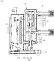
- FIG. 1 is a partial cross-sectional view showing a typical vacuum circuit breaker.
- a general vacuum circuit breaker 1 includes a main circuit 10 including a vacuum interrupter 10a, a push rod assembly 30 and a main shaft 50 for transmitting power to a contact of the vacuum interrupter 10a, and a mechanism assembly 70 that generates a driving force and is connected to the main shaft 50 to transmit the driving force thereto.
- the vacuum interrupter 10a includes a fixed electrode 14 fixedly installed inside an insulating container 12, a movable electrode 16 that moves up and down and inside the insulating container 12, a fixed contact 14a disposed at an end of the fixed electrode 14, and a movable contact 16a disposed at an end of the movable electrode 16.
- the movable contact 16a of the movable electrode 16 is in contact with the fixed contact 14a in an inserted state.
- the movable contact 16a of the movable electrode 16 is spaced from the fixed contact 14a in an open state (or "withdrawn state").
- the movable electrode 16 ascends or descends via the push rod assembly 30.
- the push rod assembly 30 inserts or withdraws the movable electrode 16.
- the main shaft 50 transmits the power of the mechanism assembly 70 to the push rod assembly 30, the push rod assembly 30 moves downwardly or upwardly.
- One end of the main shaft 50 is connected to the mechanism assembly 70, while the other end thereof pivots in one direction or the opposite direction to raise up or lower the push rod assembly 30.
- the vacuum circuit breaker 1 having the above structure has a rotary sensor 52 mounted on the main shaft 50 to measure a time duration for which the movable contact 16a is brought into the inserted state or the open state. Reliability of operation characteristics of the vacuum circuit breaker may be determined based on a measuring result from the rotary sensor 52 of whether the movable contact 16a has moved within a predetermined time duration.
- the rotary sensor has a fixed mechanical lifespan which is generally very shorter, compared to a mechanical lifespan of the vacuum circuit breaker itself. Accordingly, due to the short lifespan of the rotary sensor, the reliability of the operation characteristics of the vacuum circuit breaker may be deteriorated during long-term use thereof.
- a purpose of the present disclosure is to provide a motion sensing device for a vacuum circuit breaker capable of detecting normality or abnormality of the vacuum circuit breaker and performance deterioration thereof, and provide a vacuum circuit breaker including the same.
- One embodiment of the present disclosure provides a motion sensing device for a vacuum circuit breaker, wherein the breaker includes: a push rod assembly including a push rod movable upwardly or downwardly to insert or withdrawn a vacuum interrupter; and a main shaft having one end pivotably coupled to the mechanism assembly and the other end coupled to an end of the push rod, wherein the main shaft transmits power generated from the mechanism assembly to the push rod, wherein the motion sensing device comprises: a sensor module installed adjacent to the main shaft for sensing a motion state of the main shaft; and a bracket coupled to the sensor module and supporting the sensor module.
- a vacuum circuit breaker comprising: a main circuit having a vacuum interrupter, wherein the vacuum interrupter includes: a fixed electrode fixedly received in an insulating container; a fixed contact disposed at one end of the fixed electrode; a movable electrode installed in the insulating container, wherein the movable electrode is movable downwardly or upwardly; and a movable contact disposed at one end of the movable electrode, wherein the movable contact contacts or is spaced from the fixed contact; a push rod assembly having a push rod coupled to the other end of the movable electrode for raising up or lowering the movable electrode; a main shaft having one end coupled to the push rod and the other end pivotably coupled to a mechanism assembly, wherein the main shaft transmits a driving force to the push rod; and a motion sensing device including: a sensor module installed adjacent to the main shaft for sensing a motion state of the main shaft; and a bracket coupled to the sensor module and supporting the sensor module.
- the sensor module may include a pair of circuits facing toward each other while the main shaft is interposed therebetween; a light-emitter disposed on one of the pair of circuits and emitting light; and a light-receiver disposed on the other of the pair of circuits, and facing toward the light-emitter, and receiving light emitting from the light-emitter, wherein the bracket may be coupled to the pair of circuits.
- the sensor module may include a circuit facing toward the main shaft; and a light-emitter and a light-receiver disposed on the circuit and side by side, wherein the light-emitter and the light-receiver face toward the main shaft, wherein light emitting from the light-emitter is reflected from a plate plane of the main shaft, and the light-receiver receives the reflected light, wherein the bracket may be disposed on one side face of the main shaft.
- the motion sensing device may further include a plurality of sensing slits extending through the main shaft, wherein the light emitting from the light-emitter passes through the plurality of sensing slits, wherein the plurality of sensing slits are spaced apart from each other by a predefined spacing.
- the motion sensing device may further include a light-blocking portion disposed between adjacent ones of the plurality of sensing slits to block the light emitting from the light-emitter.
- the motion sensing device for the vacuum circuit breaker according to the present disclosure and the vacuum circuit breaker including the same detect the motion state of the main shaft.
- the stroke of the movable contact may be identified based on the motion state of the main shaft. Thus, operation abnormalities or performance deterioration of each of the main shaft and the movable contact may be detected.
- first element or layer when a first element or layer is referred to as being present "on” or “beneath” a second element or layer, the first element may be disposed directly on or beneath the second element or may be disposed indirectly on or beneath the second element with a third element or layer being disposed between the first and second elements or layers.
- FIG. 1 is a partial cross-sectional view showing a typical vacuum circuit breaker.
- FIG. 2 is a partial cross-sectional view showing a vacuum circuit breaker to which a motion sensing device according to a first embodiment of the present disclosure is applied.
- FIG. 3 is a side view showing a mounted state of the motion sensing device according to FIG. 2 .
- FIG. 4 is a plan view showing the mounted state of the motion sensing device according to FIG. 2 .
- FIG. 5 is a front view showing the mounted state of the motion sensing device according to FIG. 2 .
- FIG. 6 is a front view showing a motion state of the motion sensing device according to FIG. 2 .
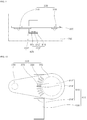
- FIG. 7 is a graph showing an output waveform of the motion sensing device and a stroke waveform of the vacuum circuit breaker according to FIG. 2 .
- a motion sensing device 800 for a vacuum circuit breaker is installed adjacent to the main shaft 300 of a vacuum circuit breaker A to detect a motion state of the main shaft 300.
- the vacuum circuit breaker A includes a main circuit 100 including a vacuum interrupter 130, a push rod assembly 200 and a main shaft 300 for transmitting power to a contact of the vacuum interrupter 130, and a mechanism assembly 400 that generates a driving force and is connected to the main shaft 300 to deliver the driving force thereto.
- the components of the vacuum circuit breaker A as described above are installed on a track assembly 700.
- the main circuit 100 has a housing 110 and the vacuum interrupter 130 installed inside the housing 110.
- the vacuum interrupter 130 includes an insulating container 132 having a receiving space defined therein, a fixed electrode 134 fixedly received in a upper portion of the insulating container 132, and a fixed contact 134a disposed at an end of the fixed electrode 134, a movable electrode 136 installed in a lower portion of the insulating container 132 to be movable up and down, and a movable contact 136a disposed at an end of the movable electrode 136.
- a arc shield 132a that creates vacuum is housed inside the insulating container 132.
- the arc shield 132a wraps around the fixed electrode 134 and the fixed contact 134a, and the movable electrode 136 and the movable contact 136a.
- the movable contact 136a may be brought into in an inserted state in which the movable contact 136a comes into contact with the fixed contact 134a under movement of the movable electrode 136 or may be brought into a withdrawn state in which the movable contact 136a is spaced from the fixed contact 134a.
- the movable electrode 136 ascends or descends under movement of the push rod assembly 200.
- the push rod assembly 200 inserts or withdraws the movable electrode 136.
- the push rod assembly 200 includes a movable rod 210 connected to the movable electrode 136 and a push rod 230 connected to the main shaft 300, and a rod housing 250 having a top coupled to the movable rod 210 and a bottom coupled to the push rod 230, and an inserting spring 270 which is accommodated inside the rod housing 250 and is compressed or restored by the push rod 230.
- the main shaft 300 is connected to the bottom of the push rod 230.
- the main shaft 300 is connected to the mechanism assembly 400 and transmits the power generated from the mechanism assembly 400 to the push rod assembly 200.
- the main shaft 300 may have a plate shape with a predefined area.
- One end of the main shaft 300 is pivotably coupled to a lower portion of a power transmission structure of the mechanism assembly 400.
- the other end of the main shaft 300 is coupled to the push rod 230.
- the main shaft 300 may have a shape that decreases in size in a direction from one end coupled to the mechanism assembly 400 to the other end coupled to the push rod 230. That is, as shown in FIG. 2 , the main shaft 300 may have one end of a shape similar to a shape of a water droplet of a large diameter.
- one end of the main shaft 300 coupled to the mechanism assembly 400 is referred to as a first pivotable portion 310, and the other end thereof is referred to as a second pivotable portion 330.
- the main shaft 300 may be pivotably coupled to a drive link not shown in the drawing.
- the main shaft 300 is installed while being exposed out of a lower bracket 510 of the mechanism assembly 400.
- the first pivotable portion 310 of the main shaft 300 pivots clockwise or counterclockwise as shown in an arrow under the driving force transmitted thereto from the mechanism assembly 400.
- the second pivotable portion 330 ascends as shown by an arrow.
- the inserting spring 270 is compressed and thus the push rod 230 pushes up the movable rod 210.
- the movable contact 136a ascends and is brought into the inserted state in which the movable contact 136a contacts the fixed contact 134a.
- the time duration for which the movable contact 136a is brought into an inserted or withdrawn state may be indirectly identified based on the motion state of the main shaft 300 or the push rod assembly 200.
- the first embodiment of the present disclosure may provide the motion sensing device 800 which may detect the motion state of the main shaft 300 to detect the time duration for which the movable contact 136a is brought into an inserted or withdrawn state, and determines operation normality or abnormality, performance deterioration or non-deterioration of the breaker A.
- the motion sensing device 800 is installed adjacent to the main shaft 300.
- the motion sensing device 800 includes a sensor module 810 for sensing a motion of the main shaft 300, and a bracket 830 on which the sensor module 810 is installed.
- the motion sensing device 800 includes a plurality of sensing slits (350 in FIG. 5 ) defined in the main shaft 300 so that the sensor module 810 may detect the motion of the main shaft 300.
- the sensor module 810 includes a light-emitter 812 that emits light, a light-receiver 814 that receives the light emitting from the light-emitter 812, and each circuit 816 that controls each of the light-emitter 812 and the light-receiver 814 and processes a signal.
- the light-emitter 812 and the light-receiver 814 are respectively installed on the circuits 816 and face toward each other.
- the sensor module 810 includes a pair of circuits 816 facing toward each other while the main shaft 300 is interposed therebetween, the light-emitter 812 disposed on one of the pair of circuits 816 to emit light, and the light-receiver 814 that is disposed on the other of the pair of circuits 816 and faces toward the light-emitter 812 and detects the light from the light-emitter 812.
- the light emitting from the light-emitter 812 passes through the main shaft 300 and is sensed by the light-receiver 814. Therefore, the light-receiver 814 generates a photocurrent proportional to an intensity of the detected light.
- the main shaft 300 is disposed between the light-emitter 812 and the light-receiver 814.
- the sensing slit 350 is defined in the main shaft 300 and will be described in detail below.
- the light from the light-emitter 812 when the light from the light-emitter 812 is blocked by the main shaft 300, the light from the light-emitter 812 may not be detected by the light-receiver 814, and thus the light-receiver 814 may not output a photocurrent.
- the circuit 816 corresponding to the light-receiver 814 derives a voltage value corresponding to an amount of the photocurrent.
- the circuit 816 may transmit the derived voltage value to an external data processing device (not shown) or a separate determination unit (not shown).
- the circuit 816 may directly use a current value corresponding to the amount of the photocurrent as a determination reference.
- the bracket 830 is coupled to the pair of circuits 816 and secures the sensor module 810 onto the track assembly 700.
- the bracket 830 must support the pair of circuits 816 so that the light-emitter 812 and the light-receiver 814 face toward each other.
- the bracket 830 has a " ⁇ " shape so that the circuits 816 may be respectively coupled to both opposing ends facing toward each other.
- two straight shaped brackets 830 may respectively be coupled to the two circuits 816 to couple the circuits 816 to the track assembly 700.
- the bracket 830 is coupled to the circuits 816 to support the circuits 816. To this end, a length of each of both opposing ends thereof to which the circuits 816 are coupled respectively is larger than a length of each of the circuits 816. Further, a width of each of both opposing ends thereof to which the circuits 816 are coupled respectively is equal to a width of each of the circuits 816.
- the main shaft 300 is disposed between the both opposing ends of the bracket 830. Therefore, the light-emitter 812 and the light-receiver 814 respectively mounted on the circuits 816 face toward each other while the main shaft 300 is interposed therebetween.
- the light emitting from the light-emitter 812 must pass through the main shaft 300 and be received by the light-receiver 814.
- the plurality of sensing slits 350 extend through the main shaft 300.
- the sensing slits 350 is adjacent to the first pivotable portion 310 of the main shaft 300, extend through a plate of the main shaft 300, and are spaced apart from each other by a predefined spacing.
- the plurality of sensing slits 350 may be arranged in a curved manner around the first pivotable portion 310.
- the first pivotable portion 310 of the main shaft 300 pivots around the second pivotable portion 330.
- the sensing slits 350 may be arranged in a curved shape corresponding to a trajectory of the pivoting motion of the main shaft 300.
- the plurality of sensing slit 350 are spaced apart from each other by a predefined spacing. Light does not pass through a portion of the main shaft 300 between the sensing slits 350. Thus, hereinafter, the portion is referred to as a light-blocking portion 370.
- a width of the sensing slit 350 may be smaller than a width of the light-blocking portion 370. In this way, the light from the light-emitter 812 may be delivered to the light-receiver 814 without affecting motion characteristics and a strength of the main shaft 300.
- the light emitting from the light-emitter 812 passes through the sensing slit 350 and is received by the light-receiver 814.
- the light-blocking portion 370 blocks the light-emitter 812
- the light is not transmitted to the light-receiver 814.
- the pivoting motion of the main shaft 300 moves the sensing slit 350 connected to the light-blocking portion 370 toward the light-emitter 812, the light is transmitted to the light-receiver 814.
- the push rod 230 moves under the motion of the main shaft 300, and thus the movable electrode 136 is driven by the push rod 230.
- the movable contact 136a is disposed at the end of the movable electrode 136.
- the motion of the main shaft 300 triggers the motion of the movable electrode 136. Therefore, a stroke graph of the movable contact 136a may be derived from an output voltage waveform graph of the sensor module 810 based on a spacing between the adjacent sensing slits 350.
- the stroke of the movable contact 136a means a speed at which the movable contact 136a hits the fixed contact 134a.
- a subject which performs the derivation of the graph of FIG. 7 , the determination of the motion abnormality or performance deterioration of the main shaft 300, the push rod 230, or the movable contact 136a, and the user notification may be an external data processing device or a determination unit which is not shown in the drawings.
- the determination unit may be included in the circuit 516.
- the sensor module 810 in which the light-emitter 812 and the light-receiver 814 face toward each other has been described.
- a sensor module 810' may include a light-emitter 812' and a light-receiver 814' which are arranged side by side with each other.
- a light-emitter 812' and a light-receiver 814' which are arranged side by side with each other.
- FIG. 8 is a side view showing a mounted state of another motion sensing device in the second embodiment of the present disclosure.
- FIG. 9 is a plan view showing the mounted state of the motion sensing device according to FIG. 8 .
- FIG. 10 is a front view showing the motion state of the motion sensing device according to FIG. 8 .
- FIG. 11 is a graph showing an output waveform of the motion sensing device and a stroke waveform of the vacuum circuit breaker according to FIG. 8 .
- the motion sensing device 800' may include the sensor module 810' and a bracket 830'.
- the sensor module 810' includes the light-emitter 812' and the light-receiver 814' which are arranged side by side with each other.
- the sensor module 810' may include one circuit 816'. Both of the light-emitter 812' and the light-receiver 814' may be installed on the same face of the circuit 816' facing toward the main shaft 300. In this connection, the light emitting from the light-emitter 812' is reflected back from a plate plane of the main shaft 300 and then the light-receiver 814' receives the reflected light.
- the sensor module 810' includes the circuit 816' facing toward one face of the main shaft 300, and the light-emitter 812' and the light-receiver 814' which are disposed on the circuit 816' and are arranged side by side with each other.
- the plurality of sensing slit 350 are defined in the main shaft 300.
- the light-receiver 814' when the light emitting from the light-emitter 812' passes through the sensing slit 350, the light may not be detected by the light-receiver 814' disposed on the same face on which the light-emitter 812' is disposed. Thus, the light-receiver 814' does not output the photocurrent. On the contrary, when the light emitting from the light-emitter 812' is reflected from the light-blocking portion 370, the light may be detected by the light-receiver 814', so that the light-receiver 814' outputs a photocurrent.
- a width of the light-blocking portion 370 is larger than a width of the sensing slit 350. Accordingly, a time duration for which the light-receiver 814' receives the light becomes larger than that in the first embodiment. Therefore, as shown in FIG. 11 , a period of an output voltage waveform of the sensor module 810' may be larger than that in the first embodiment.
- the emitting light is detected by the light-receiver 814' only when the light passes through the sensing slit 350.
- a waveform graph is derived in which a time duration for which the output voltage of the sensor module 810 is 0 is larger than a time duration for which the output voltage of the sensor module 810 is not 0.
- the emitting light is detected by the light-receiver 814' only when the light is reflected from the light-blocking portion 370.
- a waveform graph is derived in which a time duration for which the output voltage of the sensor module 810' is not 0 is larger than a time duration for which the output voltage of the sensor module 810' is 0.
- a waveform spacing per time of the main shaft 300 or a slope of the stroke graph of the movable contact 136a changes. Therefore, motion abnormality or performance deterioration of at least one of the main shaft 300, the push rod 230, and the movable contact 136a may be detected.
Landscapes
- Physics & Mathematics (AREA)
- General Physics & Mathematics (AREA)
- Engineering & Computer Science (AREA)
- Manufacturing & Machinery (AREA)
- Gas-Insulated Switchgears (AREA)
- Push-Button Switches (AREA)
- Measuring Fluid Pressure (AREA)
- Switches Operated By Changes In Physical Conditions (AREA)
Abstract
Description
- The present disclosure relates to a motion sensing device for a vacuum circuit breaker capable of detecting operation normality or abnormality of the vacuum circuit breaker, and performance deterioration thereof, and to a vacuum circuit breaker including the same.
- A vacuum circuit breaker is an electrical protector that uses dielectric strength of vacuum to protect load devices and lines from fault currents in an event of short circuits or ground faults occurring in electrical circuits.
- The vacuum circuit breaker performs power transport control and power system protection. The vacuum circuit breaker has a large breaking capacity and high reliability and safety. Since the vacuum circuit breaker may be mounted in a small installation space, the breaker may be easily applied to a voltage range from a medium voltage to high voltage.
- Hereinafter, a structure of a general vacuum circuit breaker will be briefly described.
-
FIG. 1 is a partial cross-sectional view showing a typical vacuum circuit breaker. - As shown in
FIG. 1 , a general vacuum circuit breaker 1 includes amain circuit 10 including avacuum interrupter 10a, apush rod assembly 30 and amain shaft 50 for transmitting power to a contact of thevacuum interrupter 10a, and amechanism assembly 70 that generates a driving force and is connected to themain shaft 50 to transmit the driving force thereto. - The
vacuum interrupter 10a includes afixed electrode 14 fixedly installed inside aninsulating container 12, amovable electrode 16 that moves up and down and inside theinsulating container 12, a fixedcontact 14a disposed at an end of thefixed electrode 14, and amovable contact 16a disposed at an end of themovable electrode 16. - The
movable contact 16a of the movable electrode 16is in contact with the fixedcontact 14a in an inserted state. Themovable contact 16a of themovable electrode 16 is spaced from the fixedcontact 14a in an open state (or "withdrawn state"). Themovable electrode 16 ascends or descends via thepush rod assembly 30. - The
push rod assembly 30 inserts or withdraws themovable electrode 16. When themain shaft 50 transmits the power of themechanism assembly 70 to thepush rod assembly 30, thepush rod assembly 30 moves downwardly or upwardly. One end of themain shaft 50 is connected to themechanism assembly 70, while the other end thereof pivots in one direction or the opposite direction to raise up or lower thepush rod assembly 30. - The vacuum circuit breaker 1 having the above structure has a
rotary sensor 52 mounted on themain shaft 50 to measure a time duration for which themovable contact 16a is brought into the inserted state or the open state. Reliability of operation characteristics of the vacuum circuit breaker may be determined based on a measuring result from therotary sensor 52 of whether themovable contact 16a has moved within a predetermined time duration. - However, the rotary sensor has a fixed mechanical lifespan which is generally very shorter, compared to a mechanical lifespan of the vacuum circuit breaker itself. Accordingly, due to the short lifespan of the rotary sensor, the reliability of the operation characteristics of the vacuum circuit breaker may be deteriorated during long-term use thereof.
- A purpose of the present disclosure is to provide a motion sensing device for a vacuum circuit breaker capable of detecting normality or abnormality of the vacuum circuit breaker and performance deterioration thereof, and provide a vacuum circuit breaker including the same.
- Purposes of the present disclosure are not limited to the above-mentioned purpose. Other purposes and advantages of the present disclosure that are not mentioned above may be understood based on following descriptions, and will be more clearly understood with reference to embodiments of the present disclosure. Further, it will be readily apparent that the purposes and advantages of the present disclosure may be realized using means and combinations thereof indicated in the Claims.
- One embodiment of the present disclosure provides a motion sensing device for a vacuum circuit breaker, wherein the breaker includes: a push rod assembly including a push rod movable upwardly or downwardly to insert or withdrawn a vacuum interrupter; and a main shaft having one end pivotably coupled to the mechanism assembly and the other end coupled to an end of the push rod, wherein the main shaft transmits power generated from the mechanism assembly to the push rod, wherein the motion sensing device comprises: a sensor module installed adjacent to the main shaft for sensing a motion state of the main shaft; and a bracket coupled to the sensor module and supporting the sensor module.
- Another embodiment of the present disclosure provides a vacuum circuit breaker comprising: a main circuit having a vacuum interrupter, wherein the vacuum interrupter includes: a fixed electrode fixedly received in an insulating container; a fixed contact disposed at one end of the fixed electrode; a movable electrode installed in the insulating container, wherein the movable electrode is movable downwardly or upwardly; and a movable contact disposed at one end of the movable electrode, wherein the movable contact contacts or is spaced from the fixed contact; a push rod assembly having a push rod coupled to the other end of the movable electrode for raising up or lowering the movable electrode; a main shaft having one end coupled to the push rod and the other end pivotably coupled to a mechanism assembly, wherein the main shaft transmits a driving force to the push rod; and a motion sensing device including: a sensor module installed adjacent to the main shaft for sensing a motion state of the main shaft; and a bracket coupled to the sensor module and supporting the sensor module.
- The sensor module may include a pair of circuits facing toward each other while the main shaft is interposed therebetween; a light-emitter disposed on one of the pair of circuits and emitting light; and a light-receiver disposed on the other of the pair of circuits, and facing toward the light-emitter, and receiving light emitting from the light-emitter, wherein the bracket may be coupled to the pair of circuits.
- Alternatively, the sensor module may include a circuit facing toward the main shaft; and a light-emitter and a light-receiver disposed on the circuit and side by side, wherein the light-emitter and the light-receiver face toward the main shaft, wherein light emitting from the light-emitter is reflected from a plate plane of the main shaft, and the light-receiver receives the reflected light, wherein the bracket may be disposed on one side face of the main shaft.
- The motion sensing device may further include a plurality of sensing slits extending through the main shaft, wherein the light emitting from the light-emitter passes through the plurality of sensing slits, wherein the plurality of sensing slits are spaced apart from each other by a predefined spacing.
- The motion sensing device may further include a light-blocking portion disposed between adjacent ones of the plurality of sensing slits to block the light emitting from the light-emitter.
- The motion sensing device for the vacuum circuit breaker according to the present disclosure and the vacuum circuit breaker including the same detect the motion state of the main shaft. The stroke of the movable contact may be identified based on the motion state of the main shaft. Thus, operation abnormalities or performance deterioration of each of the main shaft and the movable contact may be detected.
- The above-described effects, and specific effects of the present disclosure as not mentioned above will be described based on specific details for carrying out the disclosure.
-
-
FIG. 1 is a partial cross-sectional view showing a typical vacuum circuit breaker. -
FIG. 2 is a partial cross-sectional view showing a vacuum circuit breaker to which a motion sensing device according to a first embodiment of the present disclosure is applied. -
FIG. 3 is a side view showing a mounted state of the motion sensing device according toFIG. 2 . -
FIG. 4 is a plan view showing the mounted state of the motion sensing device according toFIG. 2 . -
FIG. 5 is a front view showing the mounted state of the motion sensing device according toFIG. 2 . -
FIG. 6 is a front view showing a motion state of the motion sensing device according toFIG. 2 . -
FIG. 7 is a graph showing an output waveform of the motion sensing device and a stroke waveform of the vacuum circuit breaker according toFIG. 2 . -
FIG. 8 is a side view showing a mounted state of another motion sensing device according to a second embodiment of the present disclosure. -
FIG. 9 is a plan view showing the mounted state of the motion sensing device according toFIG. 8 . -
FIG. 10 is a front view showing a motion state of the motion sensing device according toFIG. 8 . -
FIG. 11 is a graph showing an output waveform of the motion sensing device and a stroke waveform of a vacuum circuit breaker according toFIG. 8 . - The above objects, features and advantages will be described in detail later with reference to the accompanying drawings. Accordingly, a person with ordinary knowledge in the technical field to which the present disclosure belongs will be able to easily implement the technical idea of the present disclosure. In describing the present disclosure, when it is determined that a detailed description of a known component related to the present disclosure may unnecessarily obscure gist the present disclosure, the detailed description is omitted. Hereinafter, a preferred embodiment according to the present disclosure will be described in detail with reference to the accompanying drawings. In the drawings, the same reference numerals are used to indicate the same or similar elements.
- In addition, it will also be understood that when a first element or layer is referred to as being present "on" or "beneath" a second element or layer, the first element may be disposed directly on or beneath the second element or may be disposed indirectly on or beneath the second element with a third element or layer being disposed between the first and second elements or layers.
- It will be understood that when an element or layer is referred to as being "connected to", or "coupled to" another element or layer, it may be directly on, connected to, or coupled to the other element or layer, or one or more intervening elements or layers may be present. In addition, it will also be understood that when an element or layer is referred to as being "between" two elements or layers, it may be the only element or layer between the two elements or layers, or one or more intervening elements or layers may also be present.
-
FIG. 1 is a partial cross-sectional view showing a typical vacuum circuit breaker.FIG. 2 is a partial cross-sectional view showing a vacuum circuit breaker to which a motion sensing device according to a first embodiment of the present disclosure is applied.FIG. 3 is a side view showing a mounted state of the motion sensing device according toFIG. 2 .FIG. 4 is a plan view showing the mounted state of the motion sensing device according toFIG. 2 .FIG. 5 is a front view showing the mounted state of the motion sensing device according toFIG. 2 .FIG. 6 is a front view showing a motion state of the motion sensing device according toFIG. 2 .FIG. 7 is a graph showing an output waveform of the motion sensing device and a stroke waveform of the vacuum circuit breaker according toFIG. 2 . - As shown in
FIG. 2 , amotion sensing device 800 for a vacuum circuit breaker according to a first embodiment of the present disclosure is installed adjacent to themain shaft 300 of a vacuum circuit breaker A to detect a motion state of themain shaft 300. - A brief description of main components of the vacuum circuit breaker A is as follows (only components necessary for the description of the present disclosure among the components of the vacuum circuit breaker will be briefly described).
- The vacuum circuit breaker A includes a
main circuit 100 including avacuum interrupter 130, apush rod assembly 200 and amain shaft 300 for transmitting power to a contact of thevacuum interrupter 130, and amechanism assembly 400 that generates a driving force and is connected to themain shaft 300 to deliver the driving force thereto. The components of the vacuum circuit breaker A as described above are installed on atrack assembly 700. - The
main circuit 100 has ahousing 110 and thevacuum interrupter 130 installed inside thehousing 110. Thevacuum interrupter 130 includes an insulatingcontainer 132 having a receiving space defined therein, a fixedelectrode 134 fixedly received in a upper portion of the insulatingcontainer 132, and afixed contact 134a disposed at an end of the fixedelectrode 134, amovable electrode 136 installed in a lower portion of the insulatingcontainer 132 to be movable up and down, and amovable contact 136a disposed at an end of themovable electrode 136. - A
arc shield 132a that creates vacuum is housed inside the insulatingcontainer 132. Thearc shield 132a wraps around the fixedelectrode 134 and the fixedcontact 134a, and themovable electrode 136 and themovable contact 136a. Themovable contact 136a may be brought into in an inserted state in which themovable contact 136a comes into contact with the fixedcontact 134a under movement of themovable electrode 136 or may be brought into a withdrawn state in which themovable contact 136a is spaced from the fixedcontact 134a. Themovable electrode 136 ascends or descends under movement of thepush rod assembly 200. - The
push rod assembly 200 inserts or withdraws themovable electrode 136. Thepush rod assembly 200 includes amovable rod 210 connected to themovable electrode 136 and apush rod 230 connected to themain shaft 300, and arod housing 250 having a top coupled to themovable rod 210 and a bottom coupled to thepush rod 230, and an insertingspring 270 which is accommodated inside therod housing 250 and is compressed or restored by thepush rod 230. Themain shaft 300 is connected to the bottom of thepush rod 230. - The
main shaft 300 is connected to themechanism assembly 400 and transmits the power generated from themechanism assembly 400 to thepush rod assembly 200. Themain shaft 300 may have a plate shape with a predefined area. One end of themain shaft 300 is pivotably coupled to a lower portion of a power transmission structure of themechanism assembly 400. The other end of themain shaft 300 is coupled to thepush rod 230. Themain shaft 300 may have a shape that decreases in size in a direction from one end coupled to themechanism assembly 400 to the other end coupled to thepush rod 230. That is, as shown inFIG. 2 , themain shaft 300 may have one end of a shape similar to a shape of a water droplet of a large diameter. Hereinafter, one end of themain shaft 300 coupled to themechanism assembly 400 is referred to as a firstpivotable portion 310, and the other end thereof is referred to as a secondpivotable portion 330. - The
main shaft 300 may be pivotably coupled to a drive link not shown in the drawing. Themain shaft 300 is installed while being exposed out of alower bracket 510 of themechanism assembly 400. The firstpivotable portion 310 of themain shaft 300 pivots clockwise or counterclockwise as shown in an arrow under the driving force transmitted thereto from themechanism assembly 400. - When the first
pivotable portion 310 pivots counterclockwise, the secondpivotable portion 330 ascends as shown by an arrow. When thepush rod 230 ascends, the insertingspring 270 is compressed and thus thepush rod 230 pushes up themovable rod 210. As themovable rod 210 ascends, themovable contact 136a ascends and is brought into the inserted state in which themovable contact 136a contacts the fixedcontact 134a. - Conversely, when the first
pivotable portion 310 pivots clockwise, the secondpivotable portion 330 descends as shown by an arrow. When thepush rod 230 descends, the insertingspring 270 is restored and thus thepush rod 230 descends to its original position. As themovable rod 210 descends, themovable contact 136a descends and is brought into the withdrawn (open) state in which themovable contact 136a is spaced from the fixedcontact 134a. - Since the
main shaft 300 is connected to thepush rod assembly 200, the time duration for which themovable contact 136a is brought into an inserted or withdrawn state may be indirectly identified based on the motion state of themain shaft 300 or thepush rod assembly 200. - Accordingly, the first embodiment of the present disclosure may provide the
motion sensing device 800 which may detect the motion state of themain shaft 300 to detect the time duration for which themovable contact 136a is brought into an inserted or withdrawn state, and determines operation normality or abnormality, performance deterioration or non-deterioration of the breaker A. Themotion sensing device 800 is installed adjacent to themain shaft 300. - As shown in
FIG. 3 to FIG. 6 , themotion sensing device 800 includes asensor module 810 for sensing a motion of themain shaft 300, and abracket 830 on which thesensor module 810 is installed. Themotion sensing device 800 includes a plurality of sensing slits (350 inFIG. 5 ) defined in themain shaft 300 so that thesensor module 810 may detect the motion of themain shaft 300. - The
sensor module 810 includes a light-emitter 812 that emits light, a light-receiver 814 that receives the light emitting from the light-emitter 812, and eachcircuit 816 that controls each of the light-emitter 812 and the light-receiver 814 and processes a signal. The light-emitter 812 and the light-receiver 814 are respectively installed on thecircuits 816 and face toward each other. That is, thesensor module 810 includes a pair ofcircuits 816 facing toward each other while themain shaft 300 is interposed therebetween, the light-emitter 812 disposed on one of the pair ofcircuits 816 to emit light, and the light-receiver 814 that is disposed on the other of the pair ofcircuits 816 and faces toward the light-emitter 812 and detects the light from the light-emitter 812. - In this
sensor module 810, the light emitting from the light-emitter 812 passes through themain shaft 300 and is sensed by the light-receiver 814. Therefore, the light-receiver 814 generates a photocurrent proportional to an intensity of the detected light. - the
main shaft 300 is disposed between the light-emitter 812 and the light-receiver 814. - Therefore, when the light from the light-
emitter 812 passes through the sensing slit 350, the light from the light-emitter 812 may be detected by the light-receiver 814, and the light-receiver 814 outputs a photocurrent. The sensing slit 350 is defined in themain shaft 300 and will be described in detail below. - To the contrary, when the light from the light-
emitter 812 is blocked by themain shaft 300, the light from the light-emitter 812 may not be detected by the light-receiver 814, and thus the light-receiver 814 may not output a photocurrent. - The
circuit 816 corresponding to the light-receiver 814 derives a voltage value corresponding to an amount of the photocurrent. In addition, thecircuit 816 may transmit the derived voltage value to an external data processing device (not shown) or a separate determination unit (not shown). However, according to a setting or necessity, thecircuit 816 may directly use a current value corresponding to the amount of the photocurrent as a determination reference. - The
bracket 830 is coupled to the pair ofcircuits 816 and secures thesensor module 810 onto thetrack assembly 700. Thebracket 830 must support the pair ofcircuits 816 so that the light-emitter 812 and the light-receiver 814 face toward each other. To this end, thebracket 830 has a "⊏" shape so that thecircuits 816 may be respectively coupled to both opposing ends facing toward each other. Alternatively, two straight shapedbrackets 830 may respectively be coupled to the twocircuits 816 to couple thecircuits 816 to thetrack assembly 700. - The
bracket 830 is coupled to thecircuits 816 to support thecircuits 816. To this end, a length of each of both opposing ends thereof to which thecircuits 816 are coupled respectively is larger than a length of each of thecircuits 816. Further, a width of each of both opposing ends thereof to which thecircuits 816 are coupled respectively is equal to a width of each of thecircuits 816. - The
main shaft 300 is disposed between the both opposing ends of thebracket 830. Therefore, the light-emitter 812 and the light-receiver 814 respectively mounted on thecircuits 816 face toward each other while themain shaft 300 is interposed therebetween. For thesensor module 810 to function properly, the light emitting from the light-emitter 812 must pass through themain shaft 300 and be received by the light-receiver 814. For this purpose, the plurality of sensingslits 350 extend through themain shaft 300. - The sensing slits 350 is adjacent to the first
pivotable portion 310 of themain shaft 300, extend through a plate of themain shaft 300, and are spaced apart from each other by a predefined spacing. The plurality of sensing slits 350 may be arranged in a curved manner around the firstpivotable portion 310. - In more detail, the first
pivotable portion 310 of themain shaft 300 pivots around the secondpivotable portion 330. Correspondingly, the sensing slits 350 may be arranged in a curved shape corresponding to a trajectory of the pivoting motion of themain shaft 300. - The plurality of sensing slit 350 are spaced apart from each other by a predefined spacing. Light does not pass through a portion of the
main shaft 300 between the sensing slits 350. Thus, hereinafter, the portion is referred to as a light-blockingportion 370. - A width of the sensing slit 350 may be smaller than a width of the light-blocking
portion 370. In this way, the light from the light-emitter 812 may be delivered to the light-receiver 814 without affecting motion characteristics and a strength of themain shaft 300. - When the
main shaft 300 pivots, the light emitting from the light-emitter 812 passes through the sensing slit 350 and is received by the light-receiver 814. However, as themain shaft 300 pivots such that the light-blockingportion 370 blocks the light-emitter 812, the light is not transmitted to the light-receiver 814. Then, as the pivoting motion of themain shaft 300 moves the sensing slit 350 connected to the light-blockingportion 370 toward the light-emitter 812, the light is transmitted to the light-receiver 814. - As the pass-through and blocking of the light are sequentially repeated when the
main shaft 300 pivots, a graph shown inFIG. 7 is derived. - As shown in
FIG. 7 , when the light emitting from the light-emitter 812 is blocked by the light-blockingportion 370, there is no light detected by the light-receiver 814 of thesensor module 810. Therefore, an output voltage of thesensor module 810 is zero. After themain shaft 300 pivots by an amount equal to one light-blockingportion 370, a position of the sensing slit 350 coincides with a position of the light-emitter 812, and then the light therefrom is received by the light-receiver 814. Therefore, a certain level of an output voltage occurs because the light passes throughsensing slit 350. Then, when the light-blockingportion 370 moves and blocks the light-emitter 812, the emitting light is blocked so that the output voltage becomes 0 again. - The
push rod 230 moves under the motion of themain shaft 300, and thus themovable electrode 136 is driven by thepush rod 230. Themovable contact 136a is disposed at the end of themovable electrode 136. The motion of themain shaft 300 triggers the motion of themovable electrode 136. Therefore, a stroke graph of themovable contact 136a may be derived from an output voltage waveform graph of thesensor module 810 based on a spacing between the adjacent sensing slits 350. The stroke of themovable contact 136a means a speed at which themovable contact 136a hits the fixedcontact 134a. - When motion abnormality or performance deterioration occurs in at least one of the
main shaft 300, thepush rod 230 and themovable contact 136a, a spacing in the output voltage waveform of thesensor module 810 or a slope of the movable contact stroke graph of thesensor module 810 changes. Therefore, motion abnormality or performance deterioration of at least one of themain shaft 300, thepush rod 230, and themovable contact 136a may be detected. - In the above embodiment, a subject which performs the derivation of the graph of
FIG. 7 , the determination of the motion abnormality or performance deterioration of themain shaft 300, thepush rod 230, or themovable contact 136a, and the user notification may be an external data processing device or a determination unit which is not shown in the drawings. The determination unit may be included in the circuit 516. - In the above-described embodiment, the
sensor module 810 in which the light-emitter 812 and the light-receiver 814 face toward each other has been described. - However, according to another embodiment of the present disclosure, a sensor module 810' may include a light-emitter 812' and a light-receiver 814' which are arranged side by side with each other. Hereinafter, a detailed description of the same configuration as that of the above-described embodiment will be omitted.
-
FIG. 8 is a side view showing a mounted state of another motion sensing device in the second embodiment of the present disclosure.FIG. 9 is a plan view showing the mounted state of the motion sensing device according toFIG. 8 .FIG. 10 is a front view showing the motion state of the motion sensing device according toFIG. 8 .FIG. 11 is a graph showing an output waveform of the motion sensing device and a stroke waveform of the vacuum circuit breaker according toFIG. 8 . - As shown in
FIG. 8 to FIG. 10 , the motion sensing device 800' according to the second embodiment of the present disclosure may include the sensor module 810' and a bracket 830'. The sensor module 810' includes the light-emitter 812' and the light-receiver 814' which are arranged side by side with each other. - That is, the sensor module 810' may include one circuit 816'. Both of the light-emitter 812' and the light-receiver 814' may be installed on the same face of the circuit 816' facing toward the
main shaft 300. In this connection, the light emitting from the light-emitter 812' is reflected back from a plate plane of themain shaft 300 and then the light-receiver 814' receives the reflected light. - In other words, the sensor module 810' includes the circuit 816' facing toward one face of the
main shaft 300, and the light-emitter 812' and the light-receiver 814' which are disposed on the circuit 816' and are arranged side by side with each other. - As in the first embodiment, the plurality of sensing slit 350 are defined in the
main shaft 300. - Further, when the light emitting from the light-emitter 812' passes through the sensing slit 350, the light may not be detected by the light-receiver 814' disposed on the same face on which the light-emitter 812' is disposed. Thus, the light-receiver 814' does not output the photocurrent. On the contrary, when the light emitting from the light-emitter 812' is reflected from the light-blocking
portion 370, the light may be detected by the light-receiver 814', so that the light-receiver 814' outputs a photocurrent. - In this connection, a width of the light-blocking
portion 370 is larger than a width of thesensing slit 350. Accordingly, a time duration for which the light-receiver 814' receives the light becomes larger than that in the first embodiment. Therefore, as shown inFIG. 11 , a period of an output voltage waveform of the sensor module 810' may be larger than that in the first embodiment. - In the first embodiment, the emitting light is detected by the light-receiver 814' only when the light passes through the
sensing slit 350. Thus, a waveform graph is derived in which a time duration for which the output voltage of thesensor module 810 is 0 is larger than a time duration for which the output voltage of thesensor module 810 is not 0. - However, in the second embodiment, the emitting light is detected by the light-receiver 814' only when the light is reflected from the light-blocking
portion 370. Thus, a waveform graph is derived in which a time duration for which the output voltage of the sensor module 810' is not 0 is larger than a time duration for which the output voltage of the sensor module 810' is 0. - In addition, in the second embodiment, when motion abnormality or performance deterioration occurs in at least one of the
main shaft 300, thepush rod 230, and themovable contact 136a, a waveform spacing per time of themain shaft 300 or a slope of the stroke graph of themovable contact 136a changes. Therefore, motion abnormality or performance deterioration of at least one of themain shaft 300, thepush rod 230, and themovable contact 136a may be detected. - The present disclosure as described above may be subjected to various substitutions, modifications and changes within the scope that does not depart from the technical spirit of the present disclosure by those of ordinary skill in the technical field to which the present disclosure belongs. Thus, the present disclosure is not limited to the above-described embodiments and the attached drawings.
Claims (10)
- A motion sensing device (800) for a vacuum circuit breaker (A),
wherein the vacuum circuit breaker (A) includes:a push rod assembly (200) including a push rod (230) movable upwardly or downwardly to insert or withdrawn a vacuum interrupter (130); anda main shaft (300) having one end pivotably coupled to the mechanism assembly and the other end coupled to an end of the push rod, wherein the main shaft (300) transmits power generated from the mechanism assembly to the push rod (230), wherein the motion sensing device (800) comprises:a sensor module (810) installed adjacent to the main shaft (300) for sensing a motion state of the main shaft (300); anda bracket (830) coupled to the sensor module (810) and supporting the sensor module (810). - The motion sensing device (800) of claim 1, wherein the sensor module (810) includes:a pair of circuits facing toward each other while the main shaft (300) is interposed therebetween;a light-emitter (812) disposed on one of the pair of circuits and emitting light; anda light-receiver (814) disposed on the other of the pair of circuits, and facing toward the light-emitter (812), and receiving light emitting from the light-emitter (812),wherein the bracket (830) is coupled to the pair of circuits.
- The motion sensing device (800) of claim 1, wherein the sensor module (810) includes:a circuit (816) facing toward the main shaft (300); anda light-emitter (812) and a light-receiver (814) disposed on the circuit (816) and side by side, wherein the light-emitter (812) and the light-receiver (814) face toward the main shaft (300),wherein light emitting from the light-emitter (812) is reflected from a plate plane of the main shaft (300), and the light-receiver (814) receives the reflected light,wherein the bracket (830) is disposed on one side face of the main shaft (300).
- The motion sensing device (800) of claim 2 or 3, further comprising a plurality of sensing slits (350) extending through the main shaft (300), wherein the light emitting from the light-emitter (812) passes through the plurality of sensing slits (350), wherein the plurality of sensing slits (350) are spaced apart from each other by a predefined spacing.
- The motion sensing device (800) of claim 4, further comprising a light-blocking portion (370) disposed between adjacent ones of the plurality of sensing slits (350) to block the light emitting from the light-emitter (812),
wherein a width of each of the sensing slits (350) is smaller than a width of the light-blocking portion (370). - A vacuum circuit breaker (A) comprising:a main circuit having a vacuum interrupter (130), wherein the vacuum interrupter (130) includes:a fixed electrode (134) fixedly received in an insulating container;a fixed contact (134a) disposed at one end of the fixed electrode (134);a movable electrode (136) installed in the insulating container, wherein the movable electrode (136) is movable downwardly or upwardly; anda movable contact (136a) disposed at one end of the movable electrode (136), wherein the movable contact (136a) contacts or is spaced from the fixed contact (134a);a push rod assembly (200) having a push rod coupled to the other end of the movable electrode (136) for raising up or lowering the movable electrode (136);a main shaft (300) having one end coupled to the push rod (230) and the other end pivotably coupled to a mechanism assembly, wherein the main shaft (300) transmits a driving force to the push rod (230); anda motion sensing device (800) including:a sensor module (810') installed adjacent to the main shaft (300) for sensing a motion state of the main shaft (300); anda bracket (830) coupled to the sensor module (810) and supporting the sensor module (810).
- The vacuum circuit breaker (A) of claim 6, wherein the sensor module (810') includes:a pair of circuits (816') facing toward each other while the main shaft (300) is interposed therebetween;a light-emitter (812') disposed on one of the pair of circuits and emitting light; anda light-receiver (814') disposed on the other of the pair of circuits, and facing toward the light-emitter (812'), and receiving light emitting from the light-emitter (812'),wherein the bracket (830') is coupled to the pair of circuits.
- The vacuum circuit breaker (A) of claim 6, wherein the sensor module (810') includes:a circuit facing toward the main shaft (300); anda light-emitter (812') and a light-receiver (814') disposed on the circuit and side by side, wherein the light-emitter (812') and the light-receiver (814') face toward the main shaft (300),wherein light emitting from the light-emitter (812') is reflected from a plate plane of the main shaft (300), and the light-receiver (814') receives the reflected light,wherein the bracket (830) is disposed on one side face of the main shaft (300).
- The vacuum circuit breaker (A) of claim 7 or 8, wherein the motion sensing device (800) further includes a plurality of sensing slits (350) extending through the main shaft (300),
wherein the light emitting from the light-emitter (812') passes through the plurality of sensing slits (350), wherein the plurality of sensing slits (350) are spaced apart from each other by a predefined spacing. - The vacuum circuit breaker (A) of claim 9, wherein the motion sensing device (800) further includes a light-blocking portion (370) disposed between adjacent ones of the plurality of sensing slits (350) to block the light emitting from the light-emitter (812'),
wherein a width of each of the sensing slits (350) is smaller than a width of the light-blocking portion (370).
Applications Claiming Priority (2)
| Application Number | Priority Date | Filing Date | Title |
|---|---|---|---|
| KR1020190018660A KR102307853B1 (en) | 2019-02-18 | 2019-02-18 | Monitoring device of contacting point for a vacuum circuit breaker and vacuum circuit breaker having it |
| PCT/KR2019/011710 WO2020171327A1 (en) | 2019-02-18 | 2019-09-10 | Motion sensing device for vacuum circuit breaker and vacuum circuit breaker comprising same |
Publications (3)
| Publication Number | Publication Date |
|---|---|
| EP3929957A1 true EP3929957A1 (en) | 2021-12-29 |
| EP3929957A4 EP3929957A4 (en) | 2022-05-04 |
| EP3929957B1 EP3929957B1 (en) | 2024-02-21 |
Family
ID=72143431
Family Applications (1)
| Application Number | Title | Priority Date | Filing Date |
|---|---|---|---|
| EP19915821.3A Active EP3929957B1 (en) | 2019-02-18 | 2019-09-10 | Motion sensing device for vacuum circuit breaker and vacuum circuit breaker comprising same |
Country Status (6)
| Country | Link |
|---|---|
| US (1) | US11875954B2 (en) |
| EP (1) | EP3929957B1 (en) |
| JP (1) | JP7204935B2 (en) |
| KR (1) | KR102307853B1 (en) |
| CN (1) | CN113439319B (en) |
| WO (1) | WO2020171327A1 (en) |
Families Citing this family (5)
| Publication number | Priority date | Publication date | Assignee | Title |
|---|---|---|---|---|
| KR102608744B1 (en) * | 2021-08-06 | 2023-12-01 | 엘에스일렉트릭(주) | Vacuum circuit breaker |
| KR102652385B1 (en) * | 2021-11-01 | 2024-03-27 | 효성중공업 주식회사 | Stabilization device for linear motion device |
| US11804338B2 (en) | 2021-12-21 | 2023-10-31 | Jst Power Equipment, Inc. | Switchgear system that determines contact erosion in circuit breaker |
| US11860230B2 (en) | 2021-12-21 | 2024-01-02 | Jst Power Equipment, Inc. | Testing system that determines contact erosion in circuit breaker |
| CN114975013B (en) * | 2022-05-27 | 2025-01-10 | 杭州申发电气有限公司 | A high-precision travel monitoring system for circuit breakers |
Family Cites Families (26)
| Publication number | Priority date | Publication date | Assignee | Title |
|---|---|---|---|---|
| US3925722A (en) * | 1972-05-01 | 1975-12-09 | Gen Electric | Wear indicator for vacuum circuit interrupter |
| JPH0475225A (en) | 1990-07-18 | 1992-03-10 | Fuji Electric Co Ltd | Monitoring device for operation of vacuum switch equipment |
| JPH04123734A (en) | 1990-09-14 | 1992-04-23 | Meidensha Corp | Breaker control device |
| JPH06215669A (en) * | 1993-01-13 | 1994-08-05 | Fuji Electric Co Ltd | Dc vacuum circuit breaker |
| US6331687B1 (en) * | 1995-05-15 | 2001-12-18 | Cooper Industries Inc. | Control method and device for a switchgear actuator |
| JPH10308144A (en) * | 1997-05-09 | 1998-11-17 | Toshiba Corp | Power switch position detection device |
| DE10260248B4 (en) | 2002-12-20 | 2005-07-21 | Siemens Ag | Method for determining the remaining service life of a switching device and associated arrangement |
| US7473863B2 (en) * | 2003-02-06 | 2009-01-06 | Cooper Technologies Company | High voltage operating rod sensor and method of making the same |
| US7148677B2 (en) * | 2005-02-15 | 2006-12-12 | Eaton Corporation | Vacuum circuit interrupter including circuit monitoring leakage or loss of vacuum and method of monitoring a vacuum interrupter for leakage or loss of vacuum |
| JP2006310133A (en) * | 2005-04-28 | 2006-11-09 | Mitsubishi Electric Corp | Vacuum circuit breaker, contact slow-closing method, contact wear amount measuring method using the same, and gap length setting method between contacts |
| JP4685609B2 (en) * | 2005-11-24 | 2011-05-18 | 株式会社日立製作所 | Method and apparatus for measuring switching characteristics |
| JP2007242597A (en) * | 2006-02-07 | 2007-09-20 | Hitachi Ltd | Gas circuit breaker for electric power |
| KR101238643B1 (en) | 2009-06-25 | 2013-02-28 | 엘에스산전 주식회사 | Vacuum interrupter of vacuum circuit breaker and method for detecting the degree of vacuum in the same |
| CN102683098A (en) * | 2012-05-17 | 2012-09-19 | 芜湖明远电力设备制造有限公司 | Intelligent high-pressure vacuum circuit breaker |
| EP2682971B1 (en) * | 2012-07-03 | 2016-11-30 | ABB Schweiz AG | A device for indicating the state of a switching apparatus |
| US8952826B2 (en) * | 2012-10-03 | 2015-02-10 | Eaton Corporation | Circuit interrupter employing a linear transducer to monitor contact erosion |
| KR101382301B1 (en) | 2012-11-28 | 2014-04-07 | 한국남부발전 주식회사 | Cell output apparatus of vaccum circuit breaker |
| KR101448136B1 (en) | 2013-04-04 | 2014-10-07 | 이엔테크놀로지 주식회사 | Devise operating for vacuum circuitbreaker |
| US9633808B2 (en) * | 2014-10-06 | 2017-04-25 | Eaton Corporation | Electrical interruption apparatus with wear indicator |
| US9378901B2 (en) * | 2014-11-13 | 2016-06-28 | Eaton Corporation | Mechanical wear, wipe and stroke measurement system for circuit breakers |
| CN104701064B (en) * | 2015-03-26 | 2015-12-09 | 江苏现代电力科技股份有限公司 | AC vacuum switchgear is pressed in intelligent integrated based on flexible divide-shut brake technology |
| US9704661B2 (en) * | 2015-08-13 | 2017-07-11 | Eaton Corporation | Circuit breaker operating mechanism component monitoring system and associated method |
| US10424444B2 (en) * | 2015-12-10 | 2019-09-24 | Eaton Intelligent Power Limited | Sensor for circuit breaker open and close failure prediction |
| CN107180728B (en) * | 2016-03-11 | 2020-08-25 | Abb瑞士股份有限公司 | Solid-sealed pole and method of assembling the same |
| CN107976684B (en) | 2016-10-25 | 2023-08-04 | 日立能源瑞士股份公司 | Systems and methods for monitoring circuit breakers |
| KR101972591B1 (en) | 2017-05-22 | 2019-04-25 | 엘에스산전 주식회사 | Vacuum circuit breaker |
-
2019
- 2019-02-18 KR KR1020190018660A patent/KR102307853B1/en active Active
- 2019-09-10 JP JP2021547781A patent/JP7204935B2/en active Active
- 2019-09-10 US US17/431,785 patent/US11875954B2/en active Active
- 2019-09-10 WO PCT/KR2019/011710 patent/WO2020171327A1/en not_active Ceased
- 2019-09-10 CN CN201980092277.2A patent/CN113439319B/en active Active
- 2019-09-10 EP EP19915821.3A patent/EP3929957B1/en active Active
Also Published As
| Publication number | Publication date |
|---|---|
| KR20200100406A (en) | 2020-08-26 |
| EP3929957A4 (en) | 2022-05-04 |
| EP3929957B1 (en) | 2024-02-21 |
| KR102307853B1 (en) | 2021-09-30 |
| US20220139651A1 (en) | 2022-05-05 |
| CN113439319A (en) | 2021-09-24 |
| CN113439319B (en) | 2024-09-27 |
| WO2020171327A1 (en) | 2020-08-27 |
| JP2022520475A (en) | 2022-03-30 |
| JP7204935B2 (en) | 2023-01-16 |
| US11875954B2 (en) | 2024-01-16 |
Similar Documents
| Publication | Publication Date | Title |
|---|---|---|
| EP3929957B1 (en) | Motion sensing device for vacuum circuit breaker and vacuum circuit breaker comprising same | |
| US11821949B2 (en) | Contact monitoring device for vacuum circuit breaker and vacuum circuit breaker comprising same | |
| US10886724B2 (en) | Leakage current detection and interruption device for power cord | |
| EP2682971B1 (en) | A device for indicating the state of a switching apparatus | |
| US11005260B2 (en) | Leakage current detection and interruption device for power cord, and power connector and appliance employing the same | |
| WO2009140171A2 (en) | Receptacle with arc protection circuitry | |
| KR20200118575A (en) | Monitoring device of contacting point for a vacuum circuit breaker and vacuum circuit breaker having it | |
| WO2005122355A3 (en) | Aircraft applicable circuit imbalance detection and circuit interrupter and packaging thereof | |
| JP7263623B2 (en) | Contact monitoring device for vacuum circuit breaker and vacuum circuit breaker having the same | |
| KR102755755B1 (en) | Contact monitoring device for vacuum circuit breaker and vacuum circuit breaker having it | |
| EP2117284B1 (en) | Safety loop for a light fixture | |
| US11942291B2 (en) | Motion sensing device for vacuum circuit breaker and vacuum circuit breaker comprising same | |
| NL193741C (en) | Device for monitoring the operation of surge arresters. | |
| KR102186753B1 (en) | Monitoring device of contacting point for a vacuum circuit breaker and vacuum circuit breaker having it | |
| US20040047100A1 (en) | Thermal switch containing preflight test feature and fault location detection | |
| KR102683644B1 (en) | Monitoring device of contacting point for a vacuum circuit breaker and vacuum circuit breaker having it | |
| EP4020515B1 (en) | Circuit breaker handle indication using opto-mechanical design | |
| KR102683643B1 (en) | Monitoring device of contacting point for a vacuum circuit breaker and vacuum circuit breaker having it | |
| KR20200034337A (en) | System for fire and overheating protection of moulded case circuit breaker | |
| EP4113136A1 (en) | Testing an arc detecting system |
Legal Events
| Date | Code | Title | Description |
|---|---|---|---|
| STAA | Information on the status of an ep patent application or granted ep patent |
Free format text: STATUS: THE INTERNATIONAL PUBLICATION HAS BEEN MADE |
|
| PUAI | Public reference made under article 153(3) epc to a published international application that has entered the european phase |
Free format text: ORIGINAL CODE: 0009012 |
|
| STAA | Information on the status of an ep patent application or granted ep patent |
Free format text: STATUS: REQUEST FOR EXAMINATION WAS MADE |
|
| 17P | Request for examination filed |
Effective date: 20210916 |
|
| AK | Designated contracting states |
Kind code of ref document: A1 Designated state(s): AL AT BE BG CH CY CZ DE DK EE ES FI FR GB GR HR HU IE IS IT LI LT LU LV MC MK MT NL NO PL PT RO RS SE SI SK SM TR |
|
| A4 | Supplementary search report drawn up and despatched |
Effective date: 20220405 |
|
| RIC1 | Information provided on ipc code assigned before grant |
Ipc: H01H 11/00 20060101ALI20220330BHEP Ipc: H01H 1/00 20060101ALI20220330BHEP Ipc: H01H 33/666 20060101AFI20220330BHEP |
|
| DAV | Request for validation of the european patent (deleted) | ||
| DAX | Request for extension of the european patent (deleted) | ||
| STAA | Information on the status of an ep patent application or granted ep patent |
Free format text: STATUS: EXAMINATION IS IN PROGRESS |
|
| 17Q | First examination report despatched |
Effective date: 20230307 |
|
| GRAP | Despatch of communication of intention to grant a patent |
Free format text: ORIGINAL CODE: EPIDOSNIGR1 |
|
| STAA | Information on the status of an ep patent application or granted ep patent |
Free format text: STATUS: GRANT OF PATENT IS INTENDED |
|
| INTG | Intention to grant announced |
Effective date: 20231103 |
|
| GRAS | Grant fee paid |
Free format text: ORIGINAL CODE: EPIDOSNIGR3 |
|
| GRAA | (expected) grant |
Free format text: ORIGINAL CODE: 0009210 |
|
| STAA | Information on the status of an ep patent application or granted ep patent |
Free format text: STATUS: THE PATENT HAS BEEN GRANTED |
|
| AK | Designated contracting states |
Kind code of ref document: B1 Designated state(s): AL AT BE BG CH CY CZ DE DK EE ES FI FR GB GR HR HU IE IS IT LI LT LU LV MC MK MT NL NO PL PT RO RS SE SI SK SM TR |
|
| REG | Reference to a national code |
Ref country code: GB Ref legal event code: FG4D |
|
| REG | Reference to a national code |
Ref country code: CH Ref legal event code: EP |
|
| REG | Reference to a national code |
Ref country code: IE Ref legal event code: FG4D |
|
| REG | Reference to a national code |
Ref country code: DE Ref legal event code: R096 Ref document number: 602019047134 Country of ref document: DE |
|
| REG | Reference to a national code |
Ref country code: LT Ref legal event code: MG9D |
|
| REG | Reference to a national code |
Ref country code: NL Ref legal event code: MP Effective date: 20240221 |
|
| PG25 | Lapsed in a contracting state [announced via postgrant information from national office to epo] |
Ref country code: IS Free format text: LAPSE BECAUSE OF FAILURE TO SUBMIT A TRANSLATION OF THE DESCRIPTION OR TO PAY THE FEE WITHIN THE PRESCRIBED TIME-LIMIT Effective date: 20240621 |
|
| PG25 | Lapsed in a contracting state [announced via postgrant information from national office to epo] |
Ref country code: LT Free format text: LAPSE BECAUSE OF FAILURE TO SUBMIT A TRANSLATION OF THE DESCRIPTION OR TO PAY THE FEE WITHIN THE PRESCRIBED TIME-LIMIT Effective date: 20240221 |
|
| PG25 | Lapsed in a contracting state [announced via postgrant information from national office to epo] |
Ref country code: GR Free format text: LAPSE BECAUSE OF FAILURE TO SUBMIT A TRANSLATION OF THE DESCRIPTION OR TO PAY THE FEE WITHIN THE PRESCRIBED TIME-LIMIT Effective date: 20240522 |
|
| REG | Reference to a national code |
Ref country code: AT Ref legal event code: MK05 Ref document number: 1659850 Country of ref document: AT Kind code of ref document: T Effective date: 20240221 |
|
| PG25 | Lapsed in a contracting state [announced via postgrant information from national office to epo] |
Ref country code: HR Free format text: LAPSE BECAUSE OF FAILURE TO SUBMIT A TRANSLATION OF THE DESCRIPTION OR TO PAY THE FEE WITHIN THE PRESCRIBED TIME-LIMIT Effective date: 20240221 Ref country code: RS Free format text: LAPSE BECAUSE OF FAILURE TO SUBMIT A TRANSLATION OF THE DESCRIPTION OR TO PAY THE FEE WITHIN THE PRESCRIBED TIME-LIMIT Effective date: 20240521 Ref country code: NL Free format text: LAPSE BECAUSE OF FAILURE TO SUBMIT A TRANSLATION OF THE DESCRIPTION OR TO PAY THE FEE WITHIN THE PRESCRIBED TIME-LIMIT Effective date: 20240221 |
|
| PG25 | Lapsed in a contracting state [announced via postgrant information from national office to epo] |
Ref country code: ES Free format text: LAPSE BECAUSE OF FAILURE TO SUBMIT A TRANSLATION OF THE DESCRIPTION OR TO PAY THE FEE WITHIN THE PRESCRIBED TIME-LIMIT Effective date: 20240221 |
|
| PG25 | Lapsed in a contracting state [announced via postgrant information from national office to epo] |
Ref country code: AT Free format text: LAPSE BECAUSE OF FAILURE TO SUBMIT A TRANSLATION OF THE DESCRIPTION OR TO PAY THE FEE WITHIN THE PRESCRIBED TIME-LIMIT Effective date: 20240221 |
|
| PG25 | Lapsed in a contracting state [announced via postgrant information from national office to epo] |
Ref country code: RS Free format text: LAPSE BECAUSE OF FAILURE TO SUBMIT A TRANSLATION OF THE DESCRIPTION OR TO PAY THE FEE WITHIN THE PRESCRIBED TIME-LIMIT Effective date: 20240521 Ref country code: NO Free format text: LAPSE BECAUSE OF FAILURE TO SUBMIT A TRANSLATION OF THE DESCRIPTION OR TO PAY THE FEE WITHIN THE PRESCRIBED TIME-LIMIT Effective date: 20240521 Ref country code: NL Free format text: LAPSE BECAUSE OF FAILURE TO SUBMIT A TRANSLATION OF THE DESCRIPTION OR TO PAY THE FEE WITHIN THE PRESCRIBED TIME-LIMIT Effective date: 20240221 Ref country code: LT Free format text: LAPSE BECAUSE OF FAILURE TO SUBMIT A TRANSLATION OF THE DESCRIPTION OR TO PAY THE FEE WITHIN THE PRESCRIBED TIME-LIMIT Effective date: 20240221 Ref country code: IS Free format text: LAPSE BECAUSE OF FAILURE TO SUBMIT A TRANSLATION OF THE DESCRIPTION OR TO PAY THE FEE WITHIN THE PRESCRIBED TIME-LIMIT Effective date: 20240621 Ref country code: HR Free format text: LAPSE BECAUSE OF FAILURE TO SUBMIT A TRANSLATION OF THE DESCRIPTION OR TO PAY THE FEE WITHIN THE PRESCRIBED TIME-LIMIT Effective date: 20240221 Ref country code: GR Free format text: LAPSE BECAUSE OF FAILURE TO SUBMIT A TRANSLATION OF THE DESCRIPTION OR TO PAY THE FEE WITHIN THE PRESCRIBED TIME-LIMIT Effective date: 20240522 Ref country code: FI Free format text: LAPSE BECAUSE OF FAILURE TO SUBMIT A TRANSLATION OF THE DESCRIPTION OR TO PAY THE FEE WITHIN THE PRESCRIBED TIME-LIMIT Effective date: 20240221 Ref country code: ES Free format text: LAPSE BECAUSE OF FAILURE TO SUBMIT A TRANSLATION OF THE DESCRIPTION OR TO PAY THE FEE WITHIN THE PRESCRIBED TIME-LIMIT Effective date: 20240221 Ref country code: BG Free format text: LAPSE BECAUSE OF FAILURE TO SUBMIT A TRANSLATION OF THE DESCRIPTION OR TO PAY THE FEE WITHIN THE PRESCRIBED TIME-LIMIT Effective date: 20240221 Ref country code: AT Free format text: LAPSE BECAUSE OF FAILURE TO SUBMIT A TRANSLATION OF THE DESCRIPTION OR TO PAY THE FEE WITHIN THE PRESCRIBED TIME-LIMIT Effective date: 20240221 |
|
| PG25 | Lapsed in a contracting state [announced via postgrant information from national office to epo] |
Ref country code: PT Free format text: LAPSE BECAUSE OF FAILURE TO SUBMIT A TRANSLATION OF THE DESCRIPTION OR TO PAY THE FEE WITHIN THE PRESCRIBED TIME-LIMIT Effective date: 20240621 Ref country code: PL Free format text: LAPSE BECAUSE OF FAILURE TO SUBMIT A TRANSLATION OF THE DESCRIPTION OR TO PAY THE FEE WITHIN THE PRESCRIBED TIME-LIMIT Effective date: 20240221 |
|
| P01 | Opt-out of the competence of the unified patent court (upc) registered |
Free format text: CASE NUMBER: APP_39190/2024 Effective date: 20240702 |
|
| PG25 | Lapsed in a contracting state [announced via postgrant information from national office to epo] |
Ref country code: SE Free format text: LAPSE BECAUSE OF FAILURE TO SUBMIT A TRANSLATION OF THE DESCRIPTION OR TO PAY THE FEE WITHIN THE PRESCRIBED TIME-LIMIT Effective date: 20240221 Ref country code: PT Free format text: LAPSE BECAUSE OF FAILURE TO SUBMIT A TRANSLATION OF THE DESCRIPTION OR TO PAY THE FEE WITHIN THE PRESCRIBED TIME-LIMIT Effective date: 20240621 Ref country code: PL Free format text: LAPSE BECAUSE OF FAILURE TO SUBMIT A TRANSLATION OF THE DESCRIPTION OR TO PAY THE FEE WITHIN THE PRESCRIBED TIME-LIMIT Effective date: 20240221 Ref country code: LV Free format text: LAPSE BECAUSE OF FAILURE TO SUBMIT A TRANSLATION OF THE DESCRIPTION OR TO PAY THE FEE WITHIN THE PRESCRIBED TIME-LIMIT Effective date: 20240221 |
|
| PG25 | Lapsed in a contracting state [announced via postgrant information from national office to epo] |
Ref country code: DK Free format text: LAPSE BECAUSE OF FAILURE TO SUBMIT A TRANSLATION OF THE DESCRIPTION OR TO PAY THE FEE WITHIN THE PRESCRIBED TIME-LIMIT Effective date: 20240221 |
|
| PG25 | Lapsed in a contracting state [announced via postgrant information from national office to epo] |
Ref country code: SM Free format text: LAPSE BECAUSE OF FAILURE TO SUBMIT A TRANSLATION OF THE DESCRIPTION OR TO PAY THE FEE WITHIN THE PRESCRIBED TIME-LIMIT Effective date: 20240221 |
|
| PG25 | Lapsed in a contracting state [announced via postgrant information from national office to epo] |
Ref country code: EE Free format text: LAPSE BECAUSE OF FAILURE TO SUBMIT A TRANSLATION OF THE DESCRIPTION OR TO PAY THE FEE WITHIN THE PRESCRIBED TIME-LIMIT Effective date: 20240221 Ref country code: CZ Free format text: LAPSE BECAUSE OF FAILURE TO SUBMIT A TRANSLATION OF THE DESCRIPTION OR TO PAY THE FEE WITHIN THE PRESCRIBED TIME-LIMIT Effective date: 20240221 |
|
| PG25 | Lapsed in a contracting state [announced via postgrant information from national office to epo] |
Ref country code: SK Free format text: LAPSE BECAUSE OF FAILURE TO SUBMIT A TRANSLATION OF THE DESCRIPTION OR TO PAY THE FEE WITHIN THE PRESCRIBED TIME-LIMIT Effective date: 20240221 |
|
| PG25 | Lapsed in a contracting state [announced via postgrant information from national office to epo] |
Ref country code: SM Free format text: LAPSE BECAUSE OF FAILURE TO SUBMIT A TRANSLATION OF THE DESCRIPTION OR TO PAY THE FEE WITHIN THE PRESCRIBED TIME-LIMIT Effective date: 20240221 Ref country code: SK Free format text: LAPSE BECAUSE OF FAILURE TO SUBMIT A TRANSLATION OF THE DESCRIPTION OR TO PAY THE FEE WITHIN THE PRESCRIBED TIME-LIMIT Effective date: 20240221 Ref country code: RO Free format text: LAPSE BECAUSE OF FAILURE TO SUBMIT A TRANSLATION OF THE DESCRIPTION OR TO PAY THE FEE WITHIN THE PRESCRIBED TIME-LIMIT Effective date: 20240221 Ref country code: EE Free format text: LAPSE BECAUSE OF FAILURE TO SUBMIT A TRANSLATION OF THE DESCRIPTION OR TO PAY THE FEE WITHIN THE PRESCRIBED TIME-LIMIT Effective date: 20240221 Ref country code: DK Free format text: LAPSE BECAUSE OF FAILURE TO SUBMIT A TRANSLATION OF THE DESCRIPTION OR TO PAY THE FEE WITHIN THE PRESCRIBED TIME-LIMIT Effective date: 20240221 Ref country code: CZ Free format text: LAPSE BECAUSE OF FAILURE TO SUBMIT A TRANSLATION OF THE DESCRIPTION OR TO PAY THE FEE WITHIN THE PRESCRIBED TIME-LIMIT Effective date: 20240221 |
|
| REG | Reference to a national code |
Ref country code: DE Ref legal event code: R097 Ref document number: 602019047134 Country of ref document: DE |
|
| PG25 | Lapsed in a contracting state [announced via postgrant information from national office to epo] |
Ref country code: IT Free format text: LAPSE BECAUSE OF FAILURE TO SUBMIT A TRANSLATION OF THE DESCRIPTION OR TO PAY THE FEE WITHIN THE PRESCRIBED TIME-LIMIT Effective date: 20240221 |
|
| PLBE | No opposition filed within time limit |
Free format text: ORIGINAL CODE: 0009261 |
|
| STAA | Information on the status of an ep patent application or granted ep patent |
Free format text: STATUS: NO OPPOSITION FILED WITHIN TIME LIMIT |
|
| PG25 | Lapsed in a contracting state [announced via postgrant information from national office to epo] |
Ref country code: IT Free format text: LAPSE BECAUSE OF FAILURE TO SUBMIT A TRANSLATION OF THE DESCRIPTION OR TO PAY THE FEE WITHIN THE PRESCRIBED TIME-LIMIT Effective date: 20240221 |
|
| 26N | No opposition filed |
Effective date: 20241122 |
|
| PG25 | Lapsed in a contracting state [announced via postgrant information from national office to epo] |
Ref country code: SI Free format text: LAPSE BECAUSE OF FAILURE TO SUBMIT A TRANSLATION OF THE DESCRIPTION OR TO PAY THE FEE WITHIN THE PRESCRIBED TIME-LIMIT Effective date: 20240221 Ref country code: MC Free format text: LAPSE BECAUSE OF FAILURE TO SUBMIT A TRANSLATION OF THE DESCRIPTION OR TO PAY THE FEE WITHIN THE PRESCRIBED TIME-LIMIT Effective date: 20240221 |
|
| REG | Reference to a national code |
Ref country code: CH Ref legal event code: PL |
|
| PG25 | Lapsed in a contracting state [announced via postgrant information from national office to epo] |
Ref country code: LU Free format text: LAPSE BECAUSE OF NON-PAYMENT OF DUE FEES Effective date: 20240910 |
|
| GBPC | Gb: european patent ceased through non-payment of renewal fee |
Effective date: 20240910 |
|
| PG25 | Lapsed in a contracting state [announced via postgrant information from national office to epo] |
Ref country code: GB Free format text: LAPSE BECAUSE OF NON-PAYMENT OF DUE FEES Effective date: 20240910 |
|
| REG | Reference to a national code |
Ref country code: BE Ref legal event code: MM Effective date: 20240930 |
|
| PG25 | Lapsed in a contracting state [announced via postgrant information from national office to epo] |
Ref country code: BE Free format text: LAPSE BECAUSE OF NON-PAYMENT OF DUE FEES Effective date: 20240930 |
|
| PGFP | Annual fee paid to national office [announced via postgrant information from national office to epo] |
Ref country code: FR Payment date: 20250611 Year of fee payment: 7 |
|
| PG25 | Lapsed in a contracting state [announced via postgrant information from national office to epo] |
Ref country code: CH Free format text: LAPSE BECAUSE OF NON-PAYMENT OF DUE FEES Effective date: 20240930 |
|
| PG25 | Lapsed in a contracting state [announced via postgrant information from national office to epo] |
Ref country code: IE Free format text: LAPSE BECAUSE OF NON-PAYMENT OF DUE FEES Effective date: 20240910 |
|
| PGFP | Annual fee paid to national office [announced via postgrant information from national office to epo] |
Ref country code: DE Payment date: 20250609 Year of fee payment: 7 |
|
| PG25 | Lapsed in a contracting state [announced via postgrant information from national office to epo] |
Ref country code: CY Free format text: LAPSE BECAUSE OF FAILURE TO SUBMIT A TRANSLATION OF THE DESCRIPTION OR TO PAY THE FEE WITHIN THE PRESCRIBED TIME-LIMIT; INVALID AB INITIO Effective date: 20190910 |
|
| PG25 | Lapsed in a contracting state [announced via postgrant information from national office to epo] |
Ref country code: HU Free format text: LAPSE BECAUSE OF FAILURE TO SUBMIT A TRANSLATION OF THE DESCRIPTION OR TO PAY THE FEE WITHIN THE PRESCRIBED TIME-LIMIT; INVALID AB INITIO Effective date: 20190910 |