JP2007242597A - Gas-blast power-breaker - Google Patents

Gas-blast power-breaker Download PDF

Info

Publication number
JP2007242597A
JP2007242597A JP2007020795A JP2007020795A JP2007242597A JP 2007242597 A JP2007242597 A JP 2007242597A JP 2007020795 A JP2007020795 A JP 2007020795A JP 2007020795 A JP2007020795 A JP 2007020795A JP 2007242597 A JP2007242597 A JP 2007242597A
Authority
JP
Japan
Prior art keywords
gear
circuit breaker
gas circuit
teeth
closing
Prior art date
Legal status (The legal status is an assumption and is not a legal conclusion. Google has not performed a legal analysis and makes no representation as to the accuracy of the status listed.)
Pending
Application number
JP2007020795A
Other languages
Japanese (ja)
Inventor
Hiroaki Hashimoto
裕明 橋本
Hideo Kawamoto
英雄 河本
Kenichi Okubo
健一 大久保
Current Assignee (The listed assignees may be inaccurate. Google has not performed a legal analysis and makes no representation or warranty as to the accuracy of the list.)
Hitachi Ltd
Japan AE Power Systems Corp
Original Assignee
Hitachi Ltd
Japan AE Power Systems Corp
Priority date (The priority date is an assumption and is not a legal conclusion. Google has not performed a legal analysis and makes no representation as to the accuracy of the date listed.)
Filing date
Publication date
Application filed by Hitachi Ltd, Japan AE Power Systems Corp filed Critical Hitachi Ltd
Priority to JP2007020795A priority Critical patent/JP2007242597A/en
Publication of JP2007242597A publication Critical patent/JP2007242597A/en
Pending legal-status Critical Current

Links

Images

Abstract

<P>PROBLEM TO BE SOLVED: To improve on reliability of a gas-blast power-breaker through protection of an input control mechanism. <P>SOLUTION: The gas-blast power-breaker is provided with a breaking spring 26 and a making spring 28 opening and closing a contact, a rotating shaft 4 fixed on a concentric line with a main lever 5 and supported in free rotation inside a case 1, a gear wheel 52 fixed to the rotating shaft 4 with a partial gear 53 fitted at a part in a peripheral direction, and a pinion 51 meshing with the gear wheel and the partial gear. When the pinion continues to rotate after the making spring stores energy, meshing of the gear wheel and the pinion is released. A making spring link 27 connects the making spring and the gear wheel. An angle made by an axis line of the making spring link and an axis X1 when the energy storing of the making spring is completed is within a range of 0° and around 10°, with reference to the axis X1 passing an axial center of the rotating shaft and parallel with an action direction of the making spring. <P>COPYRIGHT: (C)2007,JPO&INPIT

Description

本発明は電力用ガス遮断器に係り、特に変電所や開閉所などの高電圧仕様に好適な電力用ガス遮断器に関するものである。   The present invention relates to a power gas circuit breaker, and more particularly to a power gas circuit breaker suitable for high voltage specifications such as a substation and a switching station.

従来の投入ばね蓄勢装置の他の例が、特許文献2に記載されている。この公報に記載のばね操作機構では、投入ばねの蓄勢装置が、一部が欠歯している大歯車とこの大歯車に噛合い駆動源により回転駆動される小歯車とを備える。大歯車の欠歯部に揺動可能な2個の同期爪を設け、投入ばねの蓄勢完了直後に小歯車と同期爪の第1歯を噛合わせ、同期爪の第2歯を閉路動作開始直後に噛合わせる。これにより、投入ばねの蓄勢完了後に電動機が回転し続けても、大歯車の同期爪の揺動により、小歯車から大歯車に過大な荷重が加わるのを回避でき、投入制御機構に過大な負荷が加わるのを防止する。   Another example of a conventional closing spring energy storage device is described in Patent Document 2. In the spring operating mechanism described in this publication, a closing spring energy storage device includes a large gear partially missing and a small gear that is rotationally driven by a meshing drive source. Two synchronous claws capable of swinging are provided in the missing tooth portion of the large gear, and immediately after the completion of the energization of the closing spring, the small gear and the first tooth of the synchronous claw are engaged, and the second tooth of the synchronous claw starts closing operation. Immediately bite. As a result, even if the electric motor continues to rotate after the completion of the charging of the closing spring, it is possible to avoid applying an excessive load from the small gear to the large gear due to the swinging of the synchronous claw of the large gear. Prevents loading.

投入ばね蓄勢装置の他の例が、特許文献3に記載されている。この公報に記載のばね操作機構では、小歯車と同一軸線上にクラッチ駆動要素を設けている。投入ばねの蓄勢が完了する瞬間にクラッチが切れて電動機からの駆動力が小歯車に伝わらないので、投入ばねの蓄勢完了後に電動機が回転し続けても、小歯車及び大歯車が駆動されない。これにより、投入制御機構に過大な負荷が加わるのを防止する。   Another example of the closing spring energy storage device is described in Patent Document 3. In the spring operating mechanism described in this publication, a clutch drive element is provided on the same axis as the small gear. Since the clutch is disengaged at the moment when the charging of the closing spring is completed and the driving force from the motor is not transmitted to the small gear, the small gear and the large gear are not driven even if the motor continues to rotate after the charging of the closing spring is completed. . This prevents an excessive load from being applied to the making control mechanism.

特開2001−283691号公報JP 2001-28391 A 特許第2529309号公報Japanese Patent No. 2529309 特許第3644187号公報Japanese Patent No. 3644187

しかしながら、上記特許文献1に記載のばね操作機構では、大歯車と小歯車とが常に噛合っているので、投入ばねの蓄勢完了後に電動機及び小歯車が回転し続けるような異常状態が発生すると、投入制御機構に過大な負荷が加わる。その結果、機構部品が破損する恐れがある。手動で小歯車を回転させるような事態が生じると、作業者が気づかずに操作し続けて、投入制御機構に過大な負荷を加えるおそれもある。   However, in the spring operation mechanism described in Patent Document 1, since the large gear and the small gear are always meshed with each other, when an abnormal state occurs in which the electric motor and the small gear continue to rotate after the energy accumulation of the closing spring is completed. An excessive load is applied to the closing control mechanism. As a result, the mechanical parts may be damaged. If a situation occurs in which the small gear is manually rotated, the operator may continue to operate without noticing, and an excessive load may be applied to the closing control mechanism.

上記特許文献2に記載のばね操作機構では、投入ばね蓄勢完了後に投入制御機構に過大な負荷が加わるのを防止できる。しかし、同期爪に衝突負荷が繰り返し発生するので、同期爪の強度を大きくしなければならない。また、次の投入動作で大歯車と小歯車が再び噛合うときに、歯面の噛合いにともないかなりの騒音が発生する。   In the spring operation mechanism described in Patent Document 2, it is possible to prevent an excessive load from being applied to the closing control mechanism after the closing spring accumulation is completed. However, since a collision load is repeatedly generated on the synchronous claw, the strength of the synchronous claw must be increased. Further, when the large gear and the small gear are meshed again in the next closing operation, considerable noise is generated as the tooth surfaces mesh.

上記特許文献3に記載のばね操作機構は、クラッチを設けて投入ばね蓄勢完了後に投入制御機構に過大な負荷が加わるのを防止している。しかし、クラッチを切るタイミングを規定するカム機構の調整に多大な時間を要する。また、カム機構が、大歯車とフレームとの間に配設されており、外部から目視で点検することが困難であるとともに、クラッチを修理交換する際には多大な工数を要する。   The spring operating mechanism described in Patent Document 3 is provided with a clutch to prevent an excessive load from being applied to the closing control mechanism after the closing spring accumulation is completed. However, it takes a lot of time to adjust the cam mechanism that defines the timing for disengaging the clutch. Further, the cam mechanism is disposed between the large gear and the frame, which is difficult to visually inspect from the outside, and requires a great number of man-hours when the clutch is repaired and replaced.

本発明は上記従来技術の不具合に鑑みなされたものであり、その目的は、投入制御機構を保護して、ガス遮断器の信頼性を向上させることにある。本発明の他の目的は、投入制御機構の保護機構を調整不要にし、交換を容易にすることにある。また、本発明の他の目的は、投入ばね蓄勢時に保護機構の状態を監視し、異常を検出することにある。   The present invention has been made in view of the above problems of the prior art, and an object thereof is to protect the closing control mechanism and improve the reliability of the gas circuit breaker. Another object of the present invention is to eliminate the need for adjustment of the protection mechanism of the input control mechanism and facilitate replacement. Another object of the present invention is to monitor the state of the protection mechanism during charging of the closing spring and detect an abnormality.

上記目的を達成する本発明の特徴は、遮断ばねと投入ばねの蓄勢力により固定接触子と可動接触子を有する接点を開閉して電力の遮断と投入を切り換える電力用ガス遮断器において、投入ばねを蓄勢する蓄勢手段を設け、この蓄勢手段は小歯車とこの小歯車に噛合う大歯車および部分歯車を有し、大歯車は周方向の一部が欠損した形状に形成されており、この欠損部に大歯車よりも噛合い強度の低い部分歯車を取り付けたことにある。そしてこの特徴において、部分歯車の歯が大歯車の歯よりも先んじて破損して小歯車との噛合いが解除するように設定するのがよい。   A feature of the present invention that achieves the above object is a power gas circuit breaker that opens and closes a contact having a fixed contact and a movable contact by a stored force of a breaking spring and a closing spring to switch between cutting off and turning on power. An accumulating means for accumulating a spring is provided, the accumulating means has a small gear, a large gear and a partial gear meshing with the small gear, and the large gear is formed in a shape in which a part of the circumferential direction is missing. The partial gear having lower meshing strength than the large gear is attached to the missing portion. And in this feature, it is preferable to set so that the teeth of the partial gear are broken earlier than the teeth of the large gear and the meshing with the small gear is released.

上記目的を達成する本発明の他の特徴は、固定接触子と可動接触子を有する接点を開閉して電力の遮断と投入を切り換える遮断部と、接点を開閉する遮断ばねおよび投入ばねと、投入ばねの駆動力をカムに伝達して遮断ばねを蓄勢し、投入ばねを電動機と歯車列により蓄勢する投入ばね蓄勢装置とを備えた電力用ガス遮断器において、カムと同心上に固定され筐体内に回動自在に支持された回転軸と、この回転軸に固定され周方向の一部に部分歯車を取り付けた大歯車と、この大歯車および部分歯車に噛合う小歯車と、投入ばねと大歯車とを接続する投入ばねリンクとを備え、回転軸の軸心を通り投入ばねの動作方向に平行な軸X1を基準として、投入ばねの蓄勢が完了する際に投入ばねリンクの軸線と軸X1とのなす角度が0°から約10°の範囲にあるものである。   Another feature of the present invention that achieves the above object is to provide a shut-off unit that opens and closes a contact having a fixed contact and a movable contact to switch power off and on, a shut-off spring that opens and closes the contact, a closing spring, and a closing A power gas circuit breaker equipped with a closing spring accumulator that transmits the driving force of the spring to the cam to store the blocking spring and stores the closing spring with an electric motor and a gear train. A rotary shaft rotatably supported in the housing, a large gear fixed to the rotary shaft and having a partial gear attached to a part of the circumferential direction, a small gear meshing with the large gear and the partial gear, A closing spring link for connecting the spring and the large gear, and when the energy storage of the closing spring is completed with reference to an axis X1 passing through the axis of the rotating shaft and parallel to the operating direction of the closing spring. Angle between axis and axis X1 is 0 ° to about 10 ° It is in the range.

そして上記いずれかの特徴において、部分歯車を大歯車に着脱自在に構成するのがよく、大歯車に着脱自在な部分歯車の歯は、大歯車の歯と同一モジュールで同一ピッチでなければならない。また、大歯車の欠損部は溝であり、この溝に部分歯車を嵌合した後にねじ締結するのがよく、大歯車と部分歯車とを異なる材質で構成してもよく、部分歯車の歯が形成された部分の幅方向長さが大歯車の歯幅より狭くてもよい。部分歯車の歯元面に幅方向に延びるスリットを形成してもよく、部分歯車の歯が形成されていない部位に、大歯車と締結するための孔を形成してもよく、部分歯車において、端部側の歯の歯面強度を他の歯よりも大としてもよい。   In any one of the above features, the partial gear is preferably configured to be detachable from the large gear, and the teeth of the partial gear that is detachable from the large gear must be the same module and pitch as the teeth of the large gear. Further, the missing part of the large gear is a groove, and it is preferable that the partial gear is fitted into the groove and then screwed. The large gear and the partial gear may be made of different materials. The width direction length of the formed part may be narrower than the tooth width of the large gear. A slit extending in the width direction may be formed in the tooth base surface of the partial gear, and a hole for fastening with the large gear may be formed in a portion where the teeth of the partial gear are not formed. The tooth surface strength of the teeth on the end side may be larger than that of the other teeth.

また、上記目的を達成する本発明の他の特徴は、大歯車および部分歯車の歯を検出するように光電センサを筐体に配設し、演算処理装置と異常状態を表示可能な表示手段を備えたことによる。そして、この特徴において、部分歯車の歯が破損していない基準状態における光電センサの出力波形を演算処理装置に蓄積しておき、部分歯車の歯が破損した場合などの異常状態を検出可能に構成するとよい。   Another feature of the present invention that achieves the above object is that a photoelectric sensor is arranged in the housing so as to detect teeth of the large gear and the partial gear, and an arithmetic processing unit and display means capable of displaying an abnormal state are provided. By preparing. In this feature, the output waveform of the photoelectric sensor in the reference state in which the teeth of the partial gears are not damaged is stored in the arithmetic processing unit, and an abnormal state such as when the teeth of the partial gears are damaged can be detected. Good.

本発明によれば、駆動源にばねを用いるガス遮断器において、投入ばねの蓄勢が完了する瞬間に小歯車と噛合う大歯車の歯を大歯車本体に着脱可能で機械的強度が大歯車本体より低い別ピースの歯としたので、投入制御機構を保護できる。また、その結果、ガス遮断器の信頼性が向上する。また、投入制御機構の保護機構の調整が不要であり、交換も容易になる。   According to the present invention, in a gas circuit breaker using a spring as a drive source, the gear of the large gear meshing with the small gear can be attached to and detached from the large gear body at the moment when the charging of the closing spring is completed, and the mechanical strength is large. Since the teeth of another piece lower than the main body are used, the closing control mechanism can be protected. As a result, the reliability of the gas circuit breaker is improved. Further, it is not necessary to adjust the protection mechanism of the closing control mechanism, and replacement is easy.

以下、本発明の実施例を、図1ないし図12を用いて説明する。   Embodiments of the present invention will be described below with reference to FIGS.

図9はガス遮断器100の正面図である。   FIG. 9 is a front view of the gas circuit breaker 100.

図9において、ガス遮断器100では、円筒形の接地容器103を架台105上に設置している。接地容器103には、絶縁性のガス、例えばSF6 ガス(6弗化硫黄ガス)が規定の圧力で封入されている。接地容器103の軸方向中間部から斜め上方に、ブッシング101,102が突き出ている。ブッシング101,102内には、変電所や開閉所の中の電線を接続して電路を構成する導体が収納されている。架台105の側部には、ガス遮断器100のばね操作機構を収納する操作箱104が取り付けられている。 In FIG. 9, in the gas circuit breaker 100, a cylindrical grounding container 103 is installed on a gantry 105. An insulating gas, for example, SF 6 gas (sulfur hexafluoride gas) is sealed in the ground container 103 at a specified pressure. Bushings 101 and 102 protrude obliquely upward from the axial middle portion of the ground container 103. In the bushings 101 and 102, the conductor which connects the electric wire in a substation or a switchyard, and comprises an electric circuit is accommodated. An operation box 104 that houses the spring operation mechanism of the gas circuit breaker 100 is attached to the side of the gantry 105.

接地容器103内には固定接触子62と可動接触子63を有する接点が配設されている。図9の状態は、接点が投入されている状態であり、可動接触子63が固定接触子62に接している。遮断動作時には、可動接触子63が固定接触子62から離れる。可動接触子63は、固定接触子62との接触端と反対端で、絶縁材64に接続されている。接地容器103に、回転軸66が回転自在に支持されている。この回転軸66に、リンク65およびリンク67の一端が固定されている。リンク65の他端は、絶縁材64の一端に接続されている。同様に、リンク67の他端は、リンク68に接続されている。   A contact having a fixed contact 62 and a movable contact 63 is disposed in the ground container 103. The state of FIG. 9 is a state in which the contact is inserted, and the movable contact 63 is in contact with the fixed contact 62. During the blocking operation, the movable contact 63 is separated from the fixed contact 62. The movable contact 63 is connected to the insulating material 64 at the end opposite to the contact end with the fixed contact 62. A rotating shaft 66 is rotatably supported by the ground container 103. One end of a link 65 and a link 67 is fixed to the rotating shaft 66. The other end of the link 65 is connected to one end of the insulating material 64. Similarly, the other end of the link 67 is connected to the link 68.

操作箱104内に、ばね操作機構の主軸4が配設されている。主軸は、回転箱104に回動自在に支持されている。主軸4を中心としてばね操作機構が配置されている。主軸4に、リンク69の一端が固定されている。リンク69の他端は、リンク68に接続されている。主軸4およびリンク69,リンク68,リンク67,回転軸66が、4節リンク機構を形成している。4節リンク機構は、ばね操作機構と遮断部とを接続する。   A main shaft 4 of a spring operation mechanism is disposed in the operation box 104. The main shaft is rotatably supported by the rotary box 104. A spring operation mechanism is arranged around the main shaft 4. One end of a link 69 is fixed to the main shaft 4. The other end of the link 69 is connected to the link 68. The main shaft 4, the link 69, the link 68, the link 67, and the rotating shaft 66 form a four-bar linkage mechanism. The four-bar linkage mechanism connects the spring operation mechanism and the blocking portion.

このように構成したガス遮断器100の動作を、以下に説明する。通電時に電力が図示しない系統から上流側のブッシング102に供給される。電力はブッシング102から接地容器103内の接点に導かれ、下流側のブッシング101を経て、再び系統に供給される。   The operation of the gas circuit breaker 100 configured as described above will be described below. When energized, electric power is supplied to the upstream bushing 102 from a system (not shown). The electric power is guided from the bushing 102 to the contact in the ground container 103, and is supplied to the system again through the bushing 101 on the downstream side.

落雷などで系統に事故が発生すると、操作箱104内の操作部を駆動して、主軸4およびリンク69を反時計回りに回転させて、リンク68を下方に移動させる。リンク68が移動すると、リンク67および回転軸66,リンク65が反時計回りに回転し、絶縁材64を左方に移動させる。固定接触子62が可動接触子63から離れて接点が開く。接点が開いたので、下流側への電力の供給が遮断される。   When an accident occurs in the system due to lightning or the like, the operation unit in the operation box 104 is driven, the main shaft 4 and the link 69 are rotated counterclockwise, and the link 68 is moved downward. When the link 68 moves, the link 67, the rotating shaft 66, and the link 65 rotate counterclockwise, and the insulating material 64 is moved to the left. The stationary contact 62 moves away from the movable contact 63 and the contact opens. Since the contact is opened, the supply of power to the downstream side is interrupted.

なお、本実施例では接地容器103を水平方向に延在しているが、鉛直方向に延在してもよい。接地容器103にブッシングを直接取り付けた単体のガス遮断器について説明するが、ガス絶縁開閉装置の中に組み込まれていてもよい。SF6 ガスを使用したガス遮断器を例にとり説明するが、真空遮断器など他の開閉装置であってもよい。 In the present embodiment, the ground container 103 extends in the horizontal direction, but may extend in the vertical direction. Although a single gas circuit breaker in which a bushing is directly attached to the ground container 103 will be described, it may be incorporated in a gas insulated switchgear. Although a gas circuit breaker using SF 6 gas will be described as an example, other switchgear such as a vacuum circuit breaker may be used.

図1から図3に、図9で示した操作箱104内に収容するばね操作機構400を模式図で示す。図1から図3に変化するにしたがって、順に遮断部接点の開閉動作が進行する。   FIGS. 1 to 3 are schematic views showing a spring operation mechanism 400 accommodated in the operation box 104 shown in FIG. As the state changes from FIG. 1 to FIG.

図1は、ばね操作機構400の投入ばね28及び遮断ばね26が共に圧縮されている投入状態を示す図である。   FIG. 1 is a view showing a closing state in which the closing spring 28 and the blocking spring 26 of the spring operating mechanism 400 are compressed together.

図2は遮断動作が終了した状態を示す図である。   FIG. 2 is a diagram illustrating a state in which the blocking operation is completed.

図3は投入動作が終了した状態であって、投入ばね28が開放状態の図である。   FIG. 3 shows a state in which the closing operation is completed and the closing spring 28 is in an open state.

この図3の状態の後に、投入ばね28を圧縮して図1の状態に戻す図である。   FIG. 4 is a view showing that the closing spring 28 is compressed and returned to the state of FIG. 1 after the state of FIG. 3.

以上の動作については、後に詳述する。   The above operation will be described in detail later.

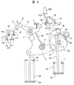
図1に示すように、ばね操作機構400は、主軸4および遮断ばね26を有する遮断操作部403と、カム軸2および投入ばね28を有する投入操作部404と、投入ばね28の駆動力を保持開放する投入制御機構402と、遮断ばね26の駆動力を保持開放する遮断制御機構401と、図3に詳細を示す投入ばね蓄勢装置405とを有している。   As shown in FIG. 1, the spring operation mechanism 400 holds the driving operation of the closing operation unit 403 having the main shaft 4 and the blocking spring 26, the closing operation unit 404 having the camshaft 2 and the closing spring 28, and the closing spring 28. A closing control mechanism 402 that opens, a blocking control mechanism 401 that holds and releases the driving force of the blocking spring 26, and a closing spring energy storage device 405 whose details are shown in FIG.

遮断操作部403の主軸4には、略Y字型の主レバー5の中間部が取り付けられている。略Y字型をした主レバー5の2つの端部には、ローラ6,7が取り付けられている。また、主レバー5の残りの端部には、遮断ばねリンク25の一端がピン25aを介して回動自在に取り付けられている。遮断ばねリンク25の他端には、フランジ34が取り付けられている。フランジ34は、遮断ばねリンク25の外周に配置された遮断ばね26を保持する。遮断ばね26は、フランジ34で保持された端部と反対側を、筐体1で保持されている。   An intermediate portion of a substantially Y-shaped main lever 5 is attached to the main shaft 4 of the shut-off operation unit 403. Rollers 6 and 7 are attached to two ends of the main lever 5 having a substantially Y shape. Further, one end of a cutoff spring link 25 is rotatably attached to the remaining end portion of the main lever 5 via a pin 25a. A flange 34 is attached to the other end of the blocking spring link 25. The flange 34 holds the cutoff spring 26 disposed on the outer periphery of the cutoff spring link 25. The blocking spring 26 is held by the housing 1 on the side opposite to the end held by the flange 34.

投入操作部404および投入ばね蓄勢装置405の構造を、図1ないし図4を用いて説明する。筐体1内に回動自在に支持されたカム軸2の一端にカム3が、他端に大歯車52が取り付けられている。大歯車52の中間部には、投入ばねリンク27の一端が回動自在に取り付けられている。投入ばねリンク27の他端部には、ばね受35が取り付けられている。ばね受35は、投入ばね28の一端側を保持する。投入ばね28は、投入ばねリンク27の外周に配置されている。ばね受35の反対側は、筐体1に保持されている。   The structure of the closing operation unit 404 and the closing spring energy storage device 405 will be described with reference to FIGS. A cam 3 is attached to one end of a cam shaft 2 rotatably supported in the housing 1 and a large gear 52 is attached to the other end. One end of the closing spring link 27 is rotatably attached to an intermediate portion of the large gear 52. A spring receiver 35 is attached to the other end of the closing spring link 27. The spring receiver 35 holds one end side of the closing spring 28. The closing spring 28 is disposed on the outer periphery of the closing spring link 27. The opposite side of the spring receiver 35 is held by the housing 1.

ここで、大歯車52の外周部の一部には、大歯車52の歯と同一モジュールで同一ピッチの歯を有する弧状の部分歯車53が取り付けられている。部分歯車53は、大歯車52の同心円状に形成した溝部に嵌合している。部分歯車53の内径側は、大歯車52の外径と同心円状をしており、側部は台形状になっている。したがって、内径側ほど周方向長さが長く、大歯車の溝に嵌合したときに遠心力で抜け出ない形状に構成されている。通常状態では、部分歯車53の歯が小歯車51の歯と噛合った状態で静止している。   Here, an arc-shaped partial gear 53 having the same module and the same pitch as the teeth of the large gear 52 is attached to a part of the outer peripheral portion of the large gear 52. The partial gear 53 is fitted in a groove formed in the concentric shape of the large gear 52. The inner diameter side of the partial gear 53 is concentric with the outer diameter of the large gear 52, and the side portion is trapezoidal. Therefore, the inner diameter side is longer in the circumferential direction, and is configured so as not to be pulled out by centrifugal force when fitted in the groove of the large gear. In the normal state, the teeth of the partial gear 53 are stationary with the teeth of the small gear 51 engaged.

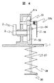
図4は歯車操作部の詳細縦断面図である。   FIG. 4 is a detailed longitudinal sectional view of the gear operation unit.

図4において、小歯車51には、図示を省略した電動機から駆動力が伝達可能である。投入ばねを蓄勢する際には、小歯車51が駆動側になり、大歯車52が従動側となる。投入動作では、逆に大歯車52が駆動側になり、小歯車51が従動側になる。小歯車51が固定された軸51aの一端は、筐体1に回動自在に支持されている。軸51aの他端には、手動操作ハンドル56を取り付ける嵌合部51bが形成されている。手動操作ハンドル56を軸51aに常時取り付ける必要はなく、手動操作時のみ取り付ける。   In FIG. 4, a driving force can be transmitted to the small gear 51 from an electric motor (not shown). When accumulating the closing spring, the small gear 51 is on the driving side and the large gear 52 is on the driven side. In the closing operation, the large gear 52 is on the driving side and the small gear 51 is on the driven side. One end of the shaft 51a to which the small gear 51 is fixed is supported by the housing 1 so as to be rotatable. A fitting portion 51b to which the manual operation handle 56 is attached is formed at the other end of the shaft 51a. The manual operation handle 56 need not always be attached to the shaft 51a, and is attached only during manual operation.

遮断操作部403に隣り合って、遮断制御機構401が配置されている。遮断制御機構401では、筐体1に固定した軸8aに、第2遮断ラッチ8の中間部が回動自在に取り付けられている。第2遮断ラッチ8の一端部に形成した係合部8bは、略Y字型の主レバー5の一端に設けたローラ7に係合する。第2遮断ラッチ8の他端部にはローラ10が取り付けられている。第2遮断ラッチ8は、軸8a部で折れ曲がった形状に形成されている。軸8aと第2遮断ラッチの係合部8bとの中間に、第2遮断ラッチ8を元の位置に復帰させる復帰ばね9の一端部が取り付けられている。この復帰ばね9の他端部は、筐体1に固定されている。   A blocking control mechanism 401 is disposed adjacent to the blocking operation unit 403. In the shut-off control mechanism 401, an intermediate portion of the second shut-off latch 8 is rotatably attached to the shaft 8 a fixed to the housing 1. An engaging portion 8 b formed at one end of the second shut-off latch 8 engages with a roller 7 provided at one end of the substantially Y-shaped main lever 5. A roller 10 is attached to the other end of the second blocking latch 8. The 2nd interruption | blocking latch 8 is formed in the shape bent by the axis | shaft 8a part. One end of a return spring 9 for returning the second blocking latch 8 to its original position is attached between the shaft 8a and the engaging portion 8b of the second blocking latch. The other end of the return spring 9 is fixed to the housing 1.

第2遮断ラッチ8の一端に設けたローラ10と係合可能に、遮断ラッチ11が配置されている。遮断ラッチ11の中間部は、筐体1に支持された軸11aに回動自在に取り付けられている。遮断ラッチ11は、軸11a部で折れ曲がった形状に形成されており、軸11aとローラ13との中間に、筐体に一端が固定された遮断ラッチ11を元の位置に復帰させる復帰ばね12の一端部が取り付けられている。遮断ラッチ11がローラ10と係合する係合部11bの反対側にはローラ13が取り付けられている。ローラ13と係合可能に、略L字形状をした遮断トリガ14aの先端部が当接している。この先端部は、曲面に形成されている。   A blocking latch 11 is disposed so as to be engageable with a roller 10 provided at one end of the second blocking latch 8. An intermediate portion of the blocking latch 11 is rotatably attached to a shaft 11 a supported by the housing 1. The shut-off latch 11 is formed in a shape bent at the shaft 11a, and a return spring 12 for returning the shut-off latch 11 having one end fixed to the housing to the original position in the middle of the shaft 11a and the roller 13. One end is attached. A roller 13 is attached to the opposite side of the engaging portion 11 b where the blocking latch 11 engages with the roller 10. The front end of a substantially L-shaped blocking trigger 14a is in contact with the roller 13 so as to be engageable with the roller 13. The tip is formed in a curved surface.

遮断トリガ14aの略L字の角部は、軸14cに取り付けられている。軸14cには水平方向に伸びる部材14bが取り付けられており、この部材14bに当接可能に遮断用電磁石201のプランジャ211が配置されている。遮断トリガ14bの中間部に、復帰ばね15が取り付けられている。復帰ばねの一端は筐体1に固定されており、遮断トリガ14を元の位置に復帰させる。   A substantially L-shaped corner of the cutoff trigger 14a is attached to the shaft 14c. A member 14b extending in the horizontal direction is attached to the shaft 14c, and a plunger 211 of the electromagnet 201 for breaking is disposed so as to be able to contact the member 14b. A return spring 15 is attached to an intermediate portion of the cutoff trigger 14b. One end of the return spring is fixed to the housing 1 and returns the cutoff trigger 14 to its original position.

投入制御機構402は、投入ラッチ19を有している。投入ラッチ19は、カム3に取り付けられたローラ18に係合可能である。投入ラッチ19は略V字形をしており、その屈曲部を軸19aに回動自在に取り付けている。投入ラッチ19のV字の一端には、カム3のローラ18に係合する係合部19bが形成されている。投入ラッチ19のV字型の他端には、ローラ21が取り付けられている。   The making control mechanism 402 has a making latch 19. The closing latch 19 can be engaged with a roller 18 attached to the cam 3. The closing latch 19 is substantially V-shaped, and its bent portion is rotatably attached to the shaft 19a. An engagement portion 19 b that engages with the roller 18 of the cam 3 is formed at one end of the V-shape of the closing latch 19. A roller 21 is attached to the other V-shaped end of the closing latch 19.

ローラ21に一端部が当接可能に、投入トリガ22が配置されている。投入トリガ22は折れ曲がった形に形成されており、その折れ曲がり部を軸22aに回動自在に取り付けられている。回転軸22aは、筐体1に回転自在に支持されている。軸19aから投入ラッチ19のローラ21までの中間に、一端が筐体1に固定された復帰ばね20が取り付けられている。投入トリガ22がローラ21に当接する側の反対端には、投入トリガ22bが形成されている。投入トリガ22bに当接可能に、投入用電磁石202のプランジャ212が配置されている。   An insertion trigger 22 is disposed so that one end of the roller 21 can come into contact with the roller 21. The throwing trigger 22 is formed in a bent shape, and the bent portion is rotatably attached to the shaft 22a. The rotating shaft 22a is rotatably supported by the housing 1. A return spring 20 having one end fixed to the housing 1 is attached in the middle from the shaft 19 a to the roller 21 of the closing latch 19. A throwing trigger 22 b is formed at the opposite end of the throwing trigger 22 that contacts the roller 21. The plunger 212 of the making electromagnet 202 is disposed so as to be able to contact the making trigger 22b.

このように構成した本実施例のガス遮断器では、第2遮断ラッチ8に取り付けた復帰ばね9、遮断ラッチ11に取り付けた復帰ばね12、遮断トリガ14aに取り付けた復帰ばね15のそれぞれは、図1に示す投入保持状態で圧縮状態になっている。本実施例ではこれらの復帰ばね9,12,15をコイルばねで形成したが、ねじりコイルばねや皿ばねなどのばねでもよい。   In the gas circuit breaker of this embodiment configured as described above, each of the return spring 9 attached to the second cutoff latch 8, the return spring 12 attached to the cutoff latch 11, and the return spring 15 attached to the cutoff trigger 14a is shown in FIG. In the input holding state shown in FIG. In the present embodiment, these return springs 9, 12, and 15 are formed by coil springs, but may be springs such as torsion coil springs and disk springs.

ガス遮断器100の動作を、以下に説明する。初めに図1に示した投入状態から遮断状態へ移行する動作について述べる。投入状態において、遮断指令が入力されると、遮断器100は遮断動作を開始する。遮断制御機構401の遮断用電磁石201が励磁され、遮断用電磁石201のプランジャ211が突出する。プランジャ211は、トリガレバー14bを押圧する。その結果、遮断トリガ14と遮断ラッチ11との係合が外れる。   The operation of the gas circuit breaker 100 will be described below. First, an operation for shifting from the on state to the cut off state shown in FIG. 1 will be described. When the interruption command is input in the on state, the circuit breaker 100 starts the interruption operation. The blocking electromagnet 201 of the blocking control mechanism 401 is excited, and the plunger 211 of the blocking electromagnet 201 protrudes. The plunger 211 presses the trigger lever 14b. As a result, the engagement between the cutoff trigger 14 and the cutoff latch 11 is released.

遮断トリガ14aとの係合が外れて、遮断ラッチ11は回動自由になる。遮断ラッチ11は、第2遮断ラッチ8のローラ10から押圧されているので、軸11a回りに左回転する。回動が規制されていた第2遮断ラッチ8が回動自由になり、主レバー5のローラ7からの押圧力により、第2遮断ラッチ8が軸8a回りに左回転する。主レバー5のローラ7と第2遮断ラッチ8との係合が外れて、主レバー5が回動自由となる。圧縮状態にある遮断ばね26の規制が外れたので、遮断ばね26が放勢され、主レバー5が反時計回りに回転する。接点の遮断動作が実行される。遮断ばね26が放勢しきると、遮断動作が終了する。主レバー5の端部のローラ6が、カム3の外周面にほぼ当接して止まる(図2参照)。   The engagement with the cutoff trigger 14a is released, and the cutoff latch 11 is free to rotate. Since the blocking latch 11 is pressed from the roller 10 of the second blocking latch 8, it rotates counterclockwise around the shaft 11a. The second blocking latch 8 whose rotation is restricted becomes free to rotate, and the pressing force from the roller 7 of the main lever 5 causes the second blocking latch 8 to rotate counterclockwise around the shaft 8a. The engagement between the roller 7 of the main lever 5 and the second blocking latch 8 is released, and the main lever 5 is freely rotatable. Since the restriction of the cutoff spring 26 in the compressed state is removed, the cutoff spring 26 is released, and the main lever 5 rotates counterclockwise. The contact breaking operation is executed. When the cutoff spring 26 is fully released, the cutoff operation is finished. The roller 6 at the end of the main lever 5 stops substantially in contact with the outer peripheral surface of the cam 3 (see FIG. 2).

接点が遮断状態から図3に示す投入状態に移る動作を、以下に説明する。図2に示す遮断状態で、遮断器100に投入指令が入力されると、投入用電磁石202が励磁される。投入用電磁石202のプランジャ212が下方向に突出し、投入トリガ22bを押圧する。投入トリガ22が反時計回りに回動し、投入ラッチ19のローラ21と投入トリガ22との係合が解除される。   The operation of moving the contact from the interrupted state to the closing state shown in FIG. 3 will be described below. When a closing command is input to the circuit breaker 100 in the blocking state shown in FIG. 2, the closing electromagnet 202 is excited. The plunger 212 of the making electromagnet 202 protrudes downward and presses the making trigger 22b. The making trigger 22 rotates counterclockwise, and the engagement between the roller 21 of the making latch 19 and the making trigger 22 is released.

回動が規制されていた投入レバー19が回動自由になり、カム3のローラ18からの押圧力により、投入ラッチ19が反時計回りに回動する。投入ラッチ19とカム3のローラ18との係合が、解除される。カム3の回動の規制がなくなったので、投入ばね28のばね力が放勢される。投入ばねリンク27が下方向に移動し、大歯車52およびカム軸2,カム3が反時計回りに回転する。   The closing lever 19 whose rotation has been restricted becomes free to rotate, and the closing latch 19 rotates counterclockwise by the pressing force from the roller 18 of the cam 3. The engagement between the closing latch 19 and the roller 18 of the cam 3 is released. Since the restriction on the rotation of the cam 3 is eliminated, the spring force of the closing spring 28 is released. The closing spring link 27 moves downward, and the large gear 52, the cam shaft 2, and the cam 3 rotate counterclockwise.

カム3の回動に伴い、カム3の外周面が主レバー5のローラ6に当接する。主レバー5が時計回りに回転する。カム3が反時計回りに略半回転すると、カム3の最大曲率半径部分でカム3の外周面が主レバー5のローラ6に当接する。このとき、主レバー5に接続した遮断ばねリンク25が、遮断ばね26をほぼ元の位置まで圧縮する。   As the cam 3 rotates, the outer peripheral surface of the cam 3 comes into contact with the roller 6 of the main lever 5. The main lever 5 rotates clockwise. When the cam 3 rotates approximately half counterclockwise, the outer peripheral surface of the cam 3 contacts the roller 6 of the main lever 5 at the maximum radius of curvature of the cam 3. At this time, the cutoff spring link 25 connected to the main lever 5 compresses the cutoff spring 26 to substantially the original position.

投入ばね28が放勢しきると、接点が投入される。なお、投入動作終了時に遮断制御機構401の各レバー8,11,14が復帰ばね9,12,15の力により元の位置に復帰する。これにより、遮断ばね26力が保持される。投入動作が終了した状態が図3である。遮断指令が入力されるとすぐに、遮断動作が可能となる。すなわち、遮断動作2回および投入動作1回の駆動エネルギーを、初回の遮断動作の前に蓄えておき、JEC−2300に規定された高速度再閉路の動作責務、O−0.35秒−CO動作が可能となる。ここで、Oは遮断動作を、COは投入動作に引き続き遮断動作を実行することである。   When the closing spring 28 is fully released, the contact is inserted. At the end of the closing operation, the levers 8, 11, and 14 of the cutoff control mechanism 401 are returned to their original positions by the force of the return springs 9, 12, and 15. As a result, the force of the cutoff spring 26 is maintained. FIG. 3 shows a state where the closing operation has been completed. As soon as the shut-off command is input, the shut-off operation becomes possible. That is, the drive energy of 2 interruption operations and 1 closing operation is stored before the first interruption operation, and the operation responsibility of the high-speed reclosing specified in JEC-2300, O-0.35 seconds-CO Operation is possible. Here, O is a shut-off operation, and CO is a shut-off operation that is performed after the closing operation.

投入動作が終了した後に、投入ばねを蓄勢する動作を以下に説明する。図3において、図示を省略した電動機と歯車列を介して小歯車51を時計回りに回転させる。小歯車51と噛合う大歯車52が反時計回りに回動する。これに伴い、投入ばねリンク27が反時計回りに揺動し、投入ばね28が圧縮される。投入ばね28を蓄勢させる時点では、小歯車51の軸心と大歯車52の軸心を結ぶ直線上に部分歯車53が位置している。   The operation of storing the closing spring after the closing operation is completed will be described below. In FIG. 3, the small gear 51 is rotated clockwise through an electric motor and a gear train (not shown). The large gear 52 that meshes with the small gear 51 rotates counterclockwise. Along with this, the closing spring link 27 swings counterclockwise, and the closing spring 28 is compressed. At the time when the closing spring 28 is stored, the partial gear 53 is positioned on a straight line connecting the axis of the small gear 51 and the axis of the large gear 52.

投入ばね28を蓄勢開始するときに、大歯車52の基準位置が鉛直下方に位置する点を基準とする。この点と大歯車52の中心を結ぶ線からの大歯車の回転角度をθで表す。すなわち、投入ばね28を蓄勢開始するときがθ=0である。大歯車52がほぼ半回転すると、図示しないリミットスイッチの指令により電動機が停止する。   When energizing the closing spring 28 is started, the reference point is that the reference position of the large gear 52 is positioned vertically downward. The rotation angle of the large gear from the line connecting this point and the center of the large gear 52 is represented by θ. That is, θ = 0 when the closing spring 28 starts to accumulate energy. When the large gear 52 rotates almost half, the electric motor is stopped by a limit switch command (not shown).

圧縮された投入ばね28の駆動力により、大歯車52がさらに反時計回りに回転しようとする。大歯車52と同軸のカム3のローラ18が投入レバー19に、投入レバー19が投入トリガ22にそれぞれ係合しているので、カム3および大歯車52の回動が阻止され、投入ばね28のばね力が保持される。これにより、図1に示すように接点が投入保持状態になり、遮断ばね26と投入ばね28が圧縮された初期状態に戻る。   Due to the driving force of the compressed closing spring 28, the large gear 52 attempts to rotate further counterclockwise. Since the roller 18 of the cam 3 coaxial with the large gear 52 is engaged with the closing lever 19 and the closing lever 19 is engaged with the closing trigger 22, the rotation of the cam 3 and the large gear 52 is prevented, and the closing spring 28 Spring force is maintained. As a result, as shown in FIG. 1, the contact is brought into the closing holding state, and the shut-off spring 26 and the closing spring 28 are returned to the compressed initial state.

通常動作において、投入ばね28を蓄勢したときに大歯車52および小歯車51の歯面に作用する荷重Fを、図8を用いて説明する。   The load F that acts on the tooth surfaces of the large gear 52 and the small gear 51 when the closing spring 28 is stored in normal operation will be described with reference to FIG.

図8の横軸は、大歯車の回転角θである。大歯車52と投入ばねリンク27は、スライダ・クランク機構を構成する。角度θが約90°で最大荷重Fmaxに達する。角度θが90°を越えると、歯面の荷重Fは減少する。大歯車52および小歯車51の諸元は、角度θが約90°のときの歯面に作用する荷重Fmaxから決定される。一方、投入ばね28の蓄勢が完了する角度θ=180°付近では、歯面の荷重Fは小さい。そこで、投入ラッチ19の諸元を投入ばね28の駆動力だけに基づいて設計する。   The horizontal axis in FIG. 8 is the rotation angle θ of the large gear. The large gear 52 and the closing spring link 27 constitute a slider / crank mechanism. The maximum load Fmax is reached when the angle θ is about 90 °. When the angle θ exceeds 90 °, the load F on the tooth surface decreases. The specifications of the large gear 52 and the small gear 51 are determined from the load Fmax acting on the tooth surface when the angle θ is about 90 °. On the other hand, in the vicinity of the angle θ = 180 ° at which the charging of the closing spring 28 is completed, the load F on the tooth surface is small. Therefore, the specifications of the closing latch 19 are designed based only on the driving force of the closing spring 28.

これに対して、投入ばね28を蓄勢した後も電動機および小歯車51が回転し続ける異常状態では、従来の蓄勢装置の大歯車52の荷重Fは、回転角度θ=180°付近で大きくなる。大歯車52が損傷する限界強度より大歯車52の応力がはるかに下回っていても、歯面の荷重Fがカム3のローラ18を介して投入レバー19に作用し、投入レバー19に過大な荷重が作用する。その結果、投入制御機構402が破損するおそれがあった。破損を回避するには、投入制御機構40の部品強度を大幅に増加させる必要があり、投入制御機構が大型化する。   On the other hand, in an abnormal state where the electric motor and the small gear 51 continue to rotate even after the closing spring 28 is stored, the load F of the large gear 52 of the conventional storage device is large near the rotation angle θ = 180 °. Become. Even if the stress of the large gear 52 is far below the limit strength at which the large gear 52 is damaged, the load F on the tooth surface acts on the closing lever 19 via the roller 18 of the cam 3 and the excessive load is applied to the closing lever 19. Works. As a result, the input control mechanism 402 may be damaged. In order to avoid damage, it is necessary to significantly increase the component strength of the input control mechanism 40, and the input control mechanism becomes larger.

このような不具合を解消するために、本実施例では、大歯車の歯の噛合い強度を部分的に低下させている。異常状態が発生したときには、強度を低下させた部分歯車53の3枚の歯53e〜53gが破損し、小歯車51との噛合いが断たれ、投入制御機構40を保護する。具体的には、部分歯車53を大歯車52より機械的強度が低い低弾性率の金属や非金属,樹脂のいずれかで構成している。   In order to eliminate such problems, in this embodiment, the meshing strength of the teeth of the large gear is partially reduced. When an abnormal state occurs, the three teeth 53e to 53g of the partial gear 53 whose strength has been reduced are damaged, the meshing with the small gear 51 is cut off, and the closing control mechanism 40 is protected. Specifically, the partial gear 53 is made of one of a low elastic modulus metal, non-metal, and resin, which has a mechanical strength lower than that of the large gear 52.

大歯車52に嵌合する部分歯車53の位置は、破損時に他の部品に影響の少ない位置に定める。具体的には、図1に示す位置とする。この状態では、投入ばね28の蓄勢が完了したときに、部分歯車53の最左側の歯53dが小歯車51とは噛合わない。本実施例によれば、異常状態で歯53e〜53gが破損しても、部分歯車53の端部の歯53dだけは破損しない。部分歯車53の歯が破損しても、次の投入動作の初期に小歯車51と部分歯車53との噛合いが復旧し、投入動作が可能となる。特に、部分歯車53の歯の破損が不完全な場合でも、投入動作初期の投入ばね28の駆動力による大歯車52の回転により、機械的強度が低い部分歯車53の歯の破損が進み、小歯車51と大歯車52とが滑らかに噛合うことが可能となる。また、投入動作終了後の投入ばねの再蓄勢動作も可能である。   The position of the partial gear 53 to be fitted to the large gear 52 is determined at a position where there is little influence on other parts at the time of breakage. Specifically, the position shown in FIG. In this state, the leftmost tooth 53 d of the partial gear 53 does not mesh with the small gear 51 when the charging of the closing spring 28 is completed. According to this embodiment, even if the teeth 53e to 53g are damaged in an abnormal state, only the teeth 53d at the end of the partial gear 53 are not damaged. Even if the teeth of the partial gear 53 are damaged, the meshing between the small gear 51 and the partial gear 53 is restored at the initial stage of the next closing operation, and the closing operation becomes possible. In particular, even if the teeth of the partial gear 53 are incompletely damaged, the rotation of the large gear 52 by the driving force of the closing spring 28 in the initial stage of the closing operation causes the damage of the teeth of the partial gear 53 having a low mechanical strength. The gear 51 and the large gear 52 can mesh smoothly. Further, it is possible to re-accumulate the closing spring after the closing operation is completed.

よって、部分歯車53の歯が破損した状態においても、遮断器の動作が可能である。ただし、破損片が他の機構部位に噛みこまれて不具合が発生するリスクがある。そこで、部分歯車の歯が破損した場合には、図2に示した投入動作終了の状態で、大歯車52から部分歯車53を取り外して交換できる。よって、短時間で遮断器を復旧できる。   Therefore, the circuit breaker can operate even when the teeth of the partial gear 53 are damaged. However, there is a risk that a broken piece is bitten by another mechanism part and a malfunction occurs. Therefore, when the teeth of the partial gear are damaged, the partial gear 53 can be removed from the large gear 52 and replaced in the state of the closing operation shown in FIG. Therefore, the circuit breaker can be restored in a short time.

本発明に係る遮断器の他の実施例を、図5ないし図7を用いて説明する。   Another embodiment of the circuit breaker according to the present invention will be described with reference to FIGS.

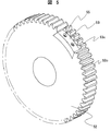
図5は投入ばね蓄勢装置が備える大歯車52と部分歯車53の斜視図である。   FIG. 5 is a perspective view of the large gear 52 and the partial gear 53 provided in the closing spring energy storage device.

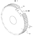
図6は部分歯車53だけの斜視図である。図7は、大歯車52だけの斜視図である。   FIG. 6 is a perspective view of only the partial gear 53. FIG. 7 is a perspective view of only the large gear 52.

本実施例では、大歯車52の歯幅b1を部分歯車53の歯幅b2より大きくする(b2<b1)。部分歯車53の歯元には、幅方向に延びるスリット53hを形成している。大歯車52に嵌合する部分の部分歯車53の幅は大歯車52と同じであるが、部分歯車53で歯が形成されていない部分には、締結用の孔53aを形成する。小ねじ55を介して部分歯車53を、大歯車52に締結固定する。大歯車52には溝部52bおよび締結用のねじ孔52aが形成されている。   In this embodiment, the tooth width b1 of the large gear 52 is made larger than the tooth width b2 of the partial gear 53 (b2 <b1). A slit 53 h extending in the width direction is formed at the tooth base of the partial gear 53. The portion of the partial gear 53 that fits into the large gear 52 has the same width as that of the large gear 52, but a fastening hole 53 a is formed in a portion of the partial gear 53 where no teeth are formed. The partial gear 53 is fastened and fixed to the large gear 52 via the small screw 55. The large gear 52 has a groove 52b and a screw hole 52a for fastening.

着脱自在の部分歯車53を大歯車に嵌合するようにしたので、大歯車52よりも機械的強度の劣る部分歯車53でも使用可能になる。その結果、投入ばね蓄勢動作中に異常事態が発生しても、部分歯車53の歯が先に破損するので投入制御機構を保護することができる。   Since the detachable partial gear 53 is fitted to the large gear, the partial gear 53 having lower mechanical strength than the large gear 52 can be used. As a result, even if an abnormal situation occurs during the closing spring accumulating operation, the teeth of the partial gear 53 are damaged first, so that the closing control mechanism can be protected.

また、歯元にスリット53hを形成したので、異常状態が発生するとスリットの形成された歯53e〜53gが他の歯に先んじて折損するので、小歯車51と確実に噛合わなくなる。小ねじ55を用いて大歯車52に部分歯車53を締結したので、部分歯車53が破損しても交換が容易になる。部分歯車53の材質は、大歯車52と同一であってもよいし、大歯車よりも強度の劣るものでもよい。また、上記実施例では、部分歯車の噛合い終り側の歯の根元にスリットを形成しないで歯面の強度を他の歯よりも大にしているが、噛合い終り側の歯の幅方向長さを長くし、他の歯にスリットを形成しないようにしても、同様の効果が得られる。   Further, since the slit 53h is formed at the tooth base, if an abnormal state occurs, the teeth 53e to 53g having the slit are broken prior to the other teeth, so that the small gear 51 is not reliably engaged. Since the partial gear 53 is fastened to the large gear 52 using the small screw 55, the replacement is easy even if the partial gear 53 is damaged. The material of the partial gear 53 may be the same as that of the large gear 52 or may be inferior in strength to the large gear. In the above embodiment, the tooth surface is made stronger than the other teeth without forming a slit at the root of the tooth at the end of meshing of the partial gear. Even if the length is increased and no slit is formed in the other teeth, the same effect can be obtained.

さらに、本発明に係る遮断器の他の実施例を図10ないし図12を用いて説明する。   Furthermore, another embodiment of the circuit breaker according to the present invention will be described with reference to FIGS.

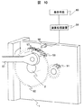
図10は部分歯車53の異常検出構成を示す図である。   FIG. 10 is a diagram showing an abnormality detection configuration of the partial gear 53.

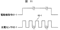
図11は部分歯車53の歯に破損が無い標準状態での電動機指令および光電センサの出力線図である。   FIG. 11 is a motor command and a photoelectric sensor output diagram in a standard state where the teeth of the partial gear 53 are not damaged.

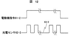
図12は部分歯車53の歯が1枚破損した異常状態での出力線図である。   FIG. 12 is an output diagram in an abnormal state where one tooth of the partial gear 53 is damaged.

図10は投入ばね蓄勢中の一状態である。光電センサ58が筐体1に固定されており、その検出面が大歯車52および部分歯車の歯の側面に対向している。光電センサ58は、演算処理装置59に接続され、この演算処理装置59と表示手段60が接続されている。   FIG. 10 shows one state during closing spring accumulation. The photoelectric sensor 58 is fixed to the housing 1, and its detection surface faces the side surfaces of the teeth of the large gear 52 and the partial gear. The photoelectric sensor 58 is connected to an arithmetic processing unit 59, and the arithmetic processing unit 59 and the display means 60 are connected.

図11の標準状態の場合、電動機が起動すると光電センサ58も起動して、それぞれ61−1および62−1の出力線図が演算処理装置59に蓄積される。光電センサは大歯車52および部分歯車53の歯を検出するとON状態となり、投射光が歯間に出て反射光が検出面に戻らない場合にはOFF状態となる。   In the case of the standard state of FIG. 11, when the electric motor is activated, the photoelectric sensor 58 is also activated, and the output diagrams of 61-1 and 62-1 are accumulated in the arithmetic processing unit 59, respectively. The photoelectric sensor is turned on when the teeth of the large gear 52 and the partial gear 53 are detected, and is turned off when the projected light comes between the teeth and the reflected light does not return to the detection surface.

一方、図10において、部分歯車53の歯57が折損した場合には、図12の63−2に示すように、光電センサの投射光が折損歯57の上方を透過するため、光電センサのOFF状態が長くなる。よって、演算処理装置59に蓄積した出力線図との比較により、部分歯車53の歯の折損を検出することができる。さらに、表示手段60に部分歯車53の歯の破損を表示することにより、遮断器の保守担当者が早期に部分歯車53の交換を行うことができる。このように、本実施例によれば、光電センサにより部分歯車53の歯の破損を早期に精度良く検出することが可能であり、遮断器の信頼性を向上させることができる。   On the other hand, in FIG. 10, when the tooth 57 of the partial gear 53 is broken, the projected light of the photoelectric sensor passes above the broken tooth 57 as indicated by 63-2 in FIG. The state becomes longer. Therefore, the tooth breakage of the partial gear 53 can be detected by comparison with the output diagram accumulated in the arithmetic processing unit 59. Further, the breaker of the tooth of the partial gear 53 is displayed on the display means 60, so that the maintenance person in charge of the circuit breaker can replace the partial gear 53 at an early stage. Thus, according to the present embodiment, it is possible to detect the breakage of the teeth of the partial gear 53 early and accurately by the photoelectric sensor, and it is possible to improve the reliability of the circuit breaker.

本発明に係る電力用ガス遮断器の一実施例の模式図。The schematic diagram of one Example of the gas circuit breaker for electric power which concerns on this invention. 図1に示した電力用ガス遮断器の操作を説明する図である。It is a figure explaining operation of the gas breaker for electric power shown in FIG. 図1に示した電力用ガス遮断器の操作を説明する図である。It is a figure explaining operation of the gas breaker for electric power shown in FIG. 図1に示した電力用ガス遮断器が有するばね蓄勢装置の正面断面図である。It is front sectional drawing of the spring energy storage apparatus which the gas breaker for electric power shown in FIG. 1 has. 図1に示した電力用ガス遮断器に用いる大歯車の他の実施例の斜視図である。It is a perspective view of the other Example of the large gearwheel used for the gas breaker for electric power shown in FIG. 図5に示した大歯車に取り付ける部分歯車の斜視図である。It is a perspective view of the partial gear attached to the large gear shown in FIG. 図5に示した大歯車から部分歯車を取り去った状態の斜視図である。FIG. 6 is a perspective view showing a state where a partial gear is removed from the large gear shown in FIG. 5. 大歯車の負荷を説明する図である。It is a figure explaining the load of a large gearwheel. 本発明に係る電力用ガス遮断器の一実施例の正面図である。It is a front view of one Example of the gas circuit breaker for electric power which concerns on this invention. 本発明に係る電力用ガス遮断器の一実施例の模式図である。It is a schematic diagram of one Example of the gas circuit breaker for electric power which concerns on this invention. 部分歯車の歯の破損が無い場合の光電センサの出力線図である。It is an output diagram of a photoelectric sensor when there is no breakage of teeth of a partial gear. 部分歯車の歯の破損が有る場合の光電センサの出力線図である。It is an output diagram of a photoelectric sensor when there is a breakage of teeth of a partial gear.

符号の説明Explanation of symbols

1…筐体、2…カム軸、3…カム、5…主レバー、26…遮断ばね、28…投入ばね、51…小歯車、52…大歯車、53…部分歯車、58…光電センサ、59…演算処理装置、60…表示手段、400…ばね操作機構、401…遮断制御機構、402…投入制御機構、403…遮断操作部、404…投入操作部、405…投入ばね蓄勢装置。 DESCRIPTION OF SYMBOLS 1 ... Housing, 2 ... Cam shaft, 3 ... Cam, 5 ... Main lever, 26 ... Shut-off spring, 28 ... Closing spring, 51 ... Small gear, 52 ... Large gear, 53 ... Partial gear, 58 ... Photoelectric sensor, 59 DESCRIPTION OF SYMBOLS ... Arithmetic processing device, 60 ... Display means, 400 ... Spring operation mechanism, 401 ... Blocking control mechanism, 402 ... Closing control mechanism, 403 ... Blocking operation unit, 404 ... Closing operation unit, 405 ... Closing spring energy storage device

Claims (15)

遮断ばねと投入ばねの蓄勢力により固定接触子と可動接触子を有する接点を開閉して電力の遮断と投入を切り換える電力用ガス遮断器において、前記投入ばねを蓄勢する蓄勢手段を設け、この蓄勢手段は小歯車とこの小歯車に噛合う大歯車および部分歯車を有し、前記大歯車は周方向の一部が欠損した形状に形成されており、この欠損部に大歯車よりも噛合い強度の低い前記部分歯車を取り付けたことを特徴とする電力用ガス遮断器。   In a power gas circuit breaker that switches between cutting off and turning on power by opening and closing a contact having a fixed contact and a movable contact by a storing power of a breaking spring and a closing spring, a storing means for storing the closing spring is provided. The energy storing means has a small gear, a large gear and a partial gear meshing with the small gear, and the large gear is formed in a shape in which a part of the circumferential direction is missing, and the missing gear is formed from the large gear. A gas circuit breaker for electric power, wherein the partial gear having a low meshing strength is attached. 前記部分歯車の歯が前記大歯車の歯よりも先んじて破損して小歯車との噛合いが解除するように設定したことを特徴とする請求項1記載の電力用ガス遮断器。   The power gas circuit breaker according to claim 1, wherein the teeth of the partial gear are set so that the teeth of the partial gear are broken earlier than the teeth of the large gear and the meshing with the small gear is released. 前記部分歯車を、大歯車に着脱自在に構成したことを特徴とする請求項1記載の電力用ガス遮断器。   2. The power gas circuit breaker according to claim 1, wherein the partial gear is configured to be detachable from a large gear. 前記大歯車に着脱自在な部分歯車の歯は、前記大歯車の歯と同一モジュールで同一ピッチであることを特徴とする請求項3記載の電力用ガス遮断器。   4. The power gas circuit breaker according to claim 3, wherein the teeth of the partial gear detachably attached to the large gear have the same module and the same pitch as the teeth of the large gear. 前記大歯車の欠損部は溝であり、この溝に前記部分歯車を嵌合した後にねじ締結したことを特徴とする請求項3記載の電力用ガス遮断器。   4. The power gas circuit breaker according to claim 3, wherein the missing portion of the large gear is a groove, and the screw is fastened after fitting the partial gear into the groove. 前記大歯車と前記部分歯車とを異なる材質で構成したことを特徴とする請求項3記載の電力用ガス遮断器。   4. The power gas circuit breaker according to claim 3, wherein the large gear and the partial gear are made of different materials. 前記部分歯車の歯が形成された部分の幅方向長さが前記大歯車の歯幅より狭いことを特徴とする請求項3記載の電力用ガス遮断器。   4. The power gas circuit breaker according to claim 3, wherein a width direction length of a portion where the teeth of the partial gear are formed is narrower than a tooth width of the large gear. 前記部分歯車の歯元面に幅方向に延びるスリットを形成したことを特徴とする請求項3記載の電力用ガス遮断器。   The power gas circuit breaker according to claim 3, wherein a slit extending in a width direction is formed on a tooth base surface of the partial gear. 前記部分歯車の歯が形成されていない部位に、前記大歯車と締結するための孔を形成したことを特徴とする請求項3記載の電力用ガス遮断器。   The power gas circuit breaker according to claim 3, wherein a hole for fastening with the large gear is formed in a portion where the teeth of the partial gear are not formed. 前記部分歯車において、端部側の歯の歯面強度を他の歯よりも大としたことを特徴とする請求項3記載の電力用ガス遮断器。   4. The power gas circuit breaker according to claim 3, wherein in the partial gear, the tooth surface strength of the teeth on the end side is made larger than those of the other teeth. 前記大歯車を回動自在に支持する筐体に光電センサを配設し、前記光電センサの検出部が前記大歯車および部分歯車の歯に対向するように構成したことを特徴とする請求項1ないし3のいずれかに記載の電力用ガス遮断器。   2. A photoelectric sensor is disposed in a casing that rotatably supports the large gear, and the detection unit of the photoelectric sensor is configured to face teeth of the large gear and the partial gear. The gas circuit breaker for electric power in any one of thru | or 3. 投入ばねの蓄勢開始時に光電センサの起動指令が入力され、投入ばね蓄勢完了後に光電センサの指令を切断するように構成したことを特徴とする請求項11記載の電力用ガス遮断器。   12. The power gas circuit breaker according to claim 11, wherein a start command for the photoelectric sensor is inputted at the start of charging of the closing spring, and the command of the photoelectric sensor is disconnected after completion of closing of the closing spring. 前記部分歯車の歯が破損していない状態における前記光電センサの出力波形を演算処理装置に蓄積しておき、前記部分歯車の歯が破損した場合などの異常状態を検出可能に構成したことを特徴とする請求項12記載の電力用ガス遮断器。   The output waveform of the photoelectric sensor in a state where the teeth of the partial gear are not damaged is stored in an arithmetic processing unit, and an abnormal state such as a case where the teeth of the partial gear are damaged can be detected. The power gas circuit breaker according to claim 12. 前記部分歯車の歯が破損した場合に、異常状態を表示可能な表示手段を備えたことを特徴とする請求項13に記載の電力用ガス遮断器。   The power gas circuit breaker according to claim 13, further comprising display means capable of displaying an abnormal state when the teeth of the partial gear are damaged. 前記演算処理装置には、前記光電センサの出力の他、開閉指令を検出するセンサや前記可動接触子のストロークを算出可能な変位センサ、あるいは接点の開閉のタイミングを検出可能なセンサなどの出力も接続されていることを特徴とする請求項14記載の電力用ガス遮断器。   In addition to the output of the photoelectric sensor, the arithmetic processing unit also has an output of a sensor that detects an opening / closing command, a displacement sensor that can calculate the stroke of the movable contactor, or a sensor that can detect the timing of opening / closing of a contact. The power gas circuit breaker according to claim 14, wherein the power gas circuit breaker is connected.
JP2007020795A 2006-02-07 2007-01-31 Gas-blast power-breaker Pending JP2007242597A (en)

Priority Applications (1)

Application Number Priority Date Filing Date Title
JP2007020795A JP2007242597A (en) 2006-02-07 2007-01-31 Gas-blast power-breaker

Applications Claiming Priority (2)

Application Number Priority Date Filing Date Title
JP2006029112 2006-02-07
JP2007020795A JP2007242597A (en) 2006-02-07 2007-01-31 Gas-blast power-breaker

Publications (1)

Publication Number Publication Date
JP2007242597A true JP2007242597A (en) 2007-09-20

Family

ID=38587908

Family Applications (1)

Application Number Title Priority Date Filing Date
JP2007020795A Pending JP2007242597A (en) 2006-02-07 2007-01-31 Gas-blast power-breaker

Country Status (1)

Country Link
JP (1) JP2007242597A (en)

Cited By (7)

* Cited by examiner, † Cited by third party
Publication number Priority date Publication date Assignee Title
JP4707759B2 (en) * 2007-03-27 2011-06-22 三菱電機株式会社 Storage mechanism for switchgear
FR2998705A1 (en) * 2012-11-28 2014-05-30 Alstom Technology Ltd SPRING-TYPE CONTROL DEVICE PARTICULARLY FOR HIGH VOLTAGE OR MEDIUM VOLTAGE CIRCUIT BREAKER OR SWITCH
KR101594264B1 (en) 2014-12-30 2016-02-15 주식회사 포스코아이씨티 Apparatus for Supplying High Voltage and Switch Over Device for Electrostatic Precipitator
JP2016225262A (en) * 2015-06-04 2016-12-28 株式会社日立製作所 Switch
CN110136555A (en) * 2019-04-29 2019-08-16 柳州铁道职业技术学院 A kind of main circuit breaker experiment rotary stand
CN113439319A (en) * 2019-02-18 2021-09-24 Ls电气株式会社 Action detection device for vacuum circuit breaker and vacuum circuit breaker comprising same
CN113690094A (en) * 2021-08-26 2021-11-23 佳质集团有限公司 Vacuum circuit breaker

Cited By (10)

* Cited by examiner, † Cited by third party
Publication number Priority date Publication date Assignee Title
JP4707759B2 (en) * 2007-03-27 2011-06-22 三菱電機株式会社 Storage mechanism for switchgear
FR2998705A1 (en) * 2012-11-28 2014-05-30 Alstom Technology Ltd SPRING-TYPE CONTROL DEVICE PARTICULARLY FOR HIGH VOLTAGE OR MEDIUM VOLTAGE CIRCUIT BREAKER OR SWITCH
WO2014083064A1 (en) * 2012-11-28 2014-06-05 Alstom Technology Ltd Control device of the spring type particularly for a high-voltage or medium-voltage circuit breaker or switch
US9672996B2 (en) 2012-11-28 2017-06-06 Alstom Technology Ltd Control device of the spring type particularly for a high-voltage or medium-voltage circuit breaker or switch
KR101594264B1 (en) 2014-12-30 2016-02-15 주식회사 포스코아이씨티 Apparatus for Supplying High Voltage and Switch Over Device for Electrostatic Precipitator
JP2016225262A (en) * 2015-06-04 2016-12-28 株式会社日立製作所 Switch
CN113439319A (en) * 2019-02-18 2021-09-24 Ls电气株式会社 Action detection device for vacuum circuit breaker and vacuum circuit breaker comprising same
CN110136555A (en) * 2019-04-29 2019-08-16 柳州铁道职业技术学院 A kind of main circuit breaker experiment rotary stand
CN113690094A (en) * 2021-08-26 2021-11-23 佳质集团有限公司 Vacuum circuit breaker
CN113690094B (en) * 2021-08-26 2023-09-08 佳质集团有限公司 Vacuum circuit breaker

Similar Documents

Publication Publication Date Title
JP2007242597A (en) Gas-blast power-breaker
CN101170027B (en) Automatic reset and self-test device particularly for residual current operated circuit breakers and the like
US6472627B1 (en) Vacuum circuit breaker
JP4482022B2 (en) Air circuit breaker switchgear
JP2007087836A (en) Gas-blast circuit breaker for electric power
JP6441747B2 (en) Switch
CN106847636B (en) A kind of electric switch-on mechanism of miniature circuit breaker
JP5711205B2 (en) Circuit breaker with mechanical trip mechanism
CN101425401B (en) Electromagnetic actuator equipped with a mechanical brake of the type with a wound-coil spring
KR101608185B1 (en) Gas circuit breaker for electric power
US5584383A (en) Operating mechanism for circuit breaker
EP0294561A2 (en) Operating mechanism for a circuit breaker
US20030034242A1 (en) Switchgear operating apparatuses
JP2010160926A (en) Fault diagnosis device and method for gas-blast circuit breaker for electric power
JP2009021248A (en) Delay time output unit of circuit breaker
TW451236B (en) Operating mechanism for a three-position switching device
CN202332707U (en) Single-module operating mechanism of vacuum circuit breaker
JP5290067B2 (en) Power circuit breaker
KR20140086651A (en) Spring operation device of circuit breaker
KR101678002B1 (en) Gas Insulated Load Break Switch
CN106449313B (en) Breaker
CN103943429A (en) Automatic reclosing device of circuit breaker
KR101412608B1 (en) Charging apparatus of vacuum circuit breaker
KR200489924Y1 (en) Circuit Breaker Simulation Tester
KR100479672B1 (en) Charging apparatus of vacuum circuit breaker