EP3929802A1 - An occupancy verification device and method - Google Patents
An occupancy verification device and method Download PDFInfo
- Publication number
- EP3929802A1 EP3929802A1 EP20207113.0A EP20207113A EP3929802A1 EP 3929802 A1 EP3929802 A1 EP 3929802A1 EP 20207113 A EP20207113 A EP 20207113A EP 3929802 A1 EP3929802 A1 EP 3929802A1
- Authority
- EP
- European Patent Office
- Prior art keywords
- data
- occupancy
- cells
- comparison
- cell
- Prior art date
- Legal status (The legal status is an assumption and is not a legal conclusion. Google has not performed a legal analysis and makes no representation as to the accuracy of the status listed.)
- Pending
Links
- 238000012795 verification Methods 0.000 title claims abstract description 78
- 238000000034 method Methods 0.000 title description 50
- 238000013528 artificial neural network Methods 0.000 claims description 23
- 230000015654 memory Effects 0.000 description 21
- 230000006870 function Effects 0.000 description 20
- 238000001514 detection method Methods 0.000 description 19
- 238000011084 recovery Methods 0.000 description 15
- 238000012549 training Methods 0.000 description 15
- 230000008447 perception Effects 0.000 description 11
- 238000010801 machine learning Methods 0.000 description 10
- 238000012545 processing Methods 0.000 description 10
- 238000013473 artificial intelligence Methods 0.000 description 9
- 238000004458 analytical method Methods 0.000 description 8
- 230000006854 communication Effects 0.000 description 7
- 238000004891 communication Methods 0.000 description 7
- 238000013459 approach Methods 0.000 description 6
- 230000005540 biological transmission Effects 0.000 description 6
- 238000013507 mapping Methods 0.000 description 6
- 230000003068 static effect Effects 0.000 description 6
- 238000004422 calculation algorithm Methods 0.000 description 5
- 238000013145 classification model Methods 0.000 description 5
- 238000003860 storage Methods 0.000 description 5
- 238000012360 testing method Methods 0.000 description 5
- 230000008859 change Effects 0.000 description 4
- 230000007613 environmental effect Effects 0.000 description 4
- 238000011156 evaluation Methods 0.000 description 4
- 230000002787 reinforcement Effects 0.000 description 4
- 230000006399 behavior Effects 0.000 description 3
- 238000013461 design Methods 0.000 description 3
- 238000009826 distribution Methods 0.000 description 3
- 238000005516 engineering process Methods 0.000 description 3
- 238000000605 extraction Methods 0.000 description 3
- 238000013178 mathematical model Methods 0.000 description 3
- 238000002604 ultrasonography Methods 0.000 description 3
- 238000010200 validation analysis Methods 0.000 description 3
- 230000001133 acceleration Effects 0.000 description 2
- 238000003491 array Methods 0.000 description 2
- 238000004364 calculation method Methods 0.000 description 2
- 238000003066 decision tree Methods 0.000 description 2
- 238000002474 experimental method Methods 0.000 description 2
- 230000004927 fusion Effects 0.000 description 2
- 230000004807 localization Effects 0.000 description 2
- 230000003287 optical effect Effects 0.000 description 2
- 239000002245 particle Substances 0.000 description 2
- 230000008569 process Effects 0.000 description 2
- 238000007637 random forest analysis Methods 0.000 description 2
- 239000013598 vector Substances 0.000 description 2
- 230000009471 action Effects 0.000 description 1
- 238000012152 algorithmic method Methods 0.000 description 1
- 230000007175 bidirectional communication Effects 0.000 description 1
- 239000000872 buffer Substances 0.000 description 1
- 230000015556 catabolic process Effects 0.000 description 1
- 230000001413 cellular effect Effects 0.000 description 1
- 238000006243 chemical reaction Methods 0.000 description 1
- 238000002485 combustion reaction Methods 0.000 description 1
- 238000013527 convolutional neural network Methods 0.000 description 1
- 230000008878 coupling Effects 0.000 description 1
- 238000010168 coupling process Methods 0.000 description 1
- 238000005859 coupling reaction Methods 0.000 description 1
- 238000013499 data model Methods 0.000 description 1
- 238000000354 decomposition reaction Methods 0.000 description 1
- 238000006731 degradation reaction Methods 0.000 description 1
- 239000012530 fluid Substances 0.000 description 1
- 239000000446 fuel Substances 0.000 description 1
- 238000003384 imaging method Methods 0.000 description 1
- 230000009349 indirect transmission Effects 0.000 description 1
- 238000003064 k means clustering Methods 0.000 description 1
- 238000012417 linear regression Methods 0.000 description 1
- 230000003137 locomotive effect Effects 0.000 description 1
- 238000007477 logistic regression Methods 0.000 description 1
- 230000007774 longterm Effects 0.000 description 1
- 238000004519 manufacturing process Methods 0.000 description 1
- 239000011159 matrix material Substances 0.000 description 1
- 238000005259 measurement Methods 0.000 description 1
- 238000012544 monitoring process Methods 0.000 description 1
- 230000000306 recurrent effect Effects 0.000 description 1
- 230000004044 response Effects 0.000 description 1
- 230000035945 sensitivity Effects 0.000 description 1
- 230000001953 sensory effect Effects 0.000 description 1
- 238000012706 support-vector machine Methods 0.000 description 1
- 230000002123 temporal effect Effects 0.000 description 1
- XLYOFNOQVPJJNP-UHFFFAOYSA-N water Substances O XLYOFNOQVPJJNP-UHFFFAOYSA-N 0.000 description 1
Images


Classifications
-
- G—PHYSICS
- G05—CONTROLLING; REGULATING
- G05D—SYSTEMS FOR CONTROLLING OR REGULATING NON-ELECTRIC VARIABLES
- G05D1/00—Control of position, course, altitude or attitude of land, water, air or space vehicles, e.g. using automatic pilots
- G05D1/02—Control of position or course in two dimensions
- G05D1/021—Control of position or course in two dimensions specially adapted to land vehicles
- G05D1/0231—Control of position or course in two dimensions specially adapted to land vehicles using optical position detecting means
- G05D1/0246—Control of position or course in two dimensions specially adapted to land vehicles using optical position detecting means using a video camera in combination with image processing means
- G05D1/0253—Control of position or course in two dimensions specially adapted to land vehicles using optical position detecting means using a video camera in combination with image processing means extracting relative motion information from a plurality of images taken successively, e.g. visual odometry, optical flow
-
- G—PHYSICS
- G06—COMPUTING; CALCULATING OR COUNTING
- G06N—COMPUTING ARRANGEMENTS BASED ON SPECIFIC COMPUTATIONAL MODELS
- G06N20/00—Machine learning
-
- G—PHYSICS
- G06—COMPUTING; CALCULATING OR COUNTING
- G06T—IMAGE DATA PROCESSING OR GENERATION, IN GENERAL
- G06T7/00—Image analysis
- G06T7/0002—Inspection of images, e.g. flaw detection
-
- B—PERFORMING OPERATIONS; TRANSPORTING
- B60—VEHICLES IN GENERAL
- B60W—CONJOINT CONTROL OF VEHICLE SUB-UNITS OF DIFFERENT TYPE OR DIFFERENT FUNCTION; CONTROL SYSTEMS SPECIALLY ADAPTED FOR HYBRID VEHICLES; ROAD VEHICLE DRIVE CONTROL SYSTEMS FOR PURPOSES NOT RELATED TO THE CONTROL OF A PARTICULAR SUB-UNIT
- B60W60/00—Drive control systems specially adapted for autonomous road vehicles
- B60W60/001—Planning or execution of driving tasks
- B60W60/0015—Planning or execution of driving tasks specially adapted for safety
- B60W60/0016—Planning or execution of driving tasks specially adapted for safety of the vehicle or its occupants
-
- G—PHYSICS
- G05—CONTROLLING; REGULATING
- G05D—SYSTEMS FOR CONTROLLING OR REGULATING NON-ELECTRIC VARIABLES
- G05D1/00—Control of position, course, altitude or attitude of land, water, air or space vehicles, e.g. using automatic pilots
- G05D1/02—Control of position or course in two dimensions
- G05D1/021—Control of position or course in two dimensions specially adapted to land vehicles
- G05D1/0212—Control of position or course in two dimensions specially adapted to land vehicles with means for defining a desired trajectory
- G05D1/0217—Control of position or course in two dimensions specially adapted to land vehicles with means for defining a desired trajectory in accordance with energy consumption, time reduction or distance reduction criteria
-
- G—PHYSICS
- G06—COMPUTING; CALCULATING OR COUNTING
- G06F—ELECTRIC DIGITAL DATA PROCESSING
- G06F18/00—Pattern recognition
- G06F18/20—Analysing
- G06F18/22—Matching criteria, e.g. proximity measures
-
- G—PHYSICS
- G06—COMPUTING; CALCULATING OR COUNTING
- G06N—COMPUTING ARRANGEMENTS BASED ON SPECIFIC COMPUTATIONAL MODELS
- G06N3/00—Computing arrangements based on biological models
- G06N3/02—Neural networks
- G06N3/04—Architecture, e.g. interconnection topology
-
- G—PHYSICS
- G06—COMPUTING; CALCULATING OR COUNTING
- G06T—IMAGE DATA PROCESSING OR GENERATION, IN GENERAL
- G06T7/00—Image analysis
- G06T7/70—Determining position or orientation of objects or cameras
-
- G—PHYSICS
- G06—COMPUTING; CALCULATING OR COUNTING
- G06V—IMAGE OR VIDEO RECOGNITION OR UNDERSTANDING
- G06V20/00—Scenes; Scene-specific elements
- G06V20/50—Context or environment of the image
- G06V20/56—Context or environment of the image exterior to a vehicle by using sensors mounted on the vehicle
- G06V20/58—Recognition of moving objects or obstacles, e.g. vehicles or pedestrians; Recognition of traffic objects, e.g. traffic signs, traffic lights or roads
-
- G—PHYSICS
- G06—COMPUTING; CALCULATING OR COUNTING
- G06T—IMAGE DATA PROCESSING OR GENERATION, IN GENERAL
- G06T2207/00—Indexing scheme for image analysis or image enhancement
- G06T2207/20—Special algorithmic details
- G06T2207/20084—Artificial neural networks [ANN]
-
- G—PHYSICS
- G06—COMPUTING; CALCULATING OR COUNTING
- G06T—IMAGE DATA PROCESSING OR GENERATION, IN GENERAL
- G06T2207/00—Indexing scheme for image analysis or image enhancement
- G06T2207/30—Subject of image; Context of image processing
- G06T2207/30168—Image quality inspection
-
- G—PHYSICS
- G06—COMPUTING; CALCULATING OR COUNTING
- G06T—IMAGE DATA PROCESSING OR GENERATION, IN GENERAL
- G06T2207/00—Indexing scheme for image analysis or image enhancement
- G06T2207/30—Subject of image; Context of image processing
- G06T2207/30248—Vehicle exterior or interior
- G06T2207/30252—Vehicle exterior; Vicinity of vehicle
Definitions
- Various aspects of this disclosure generally relate to driving safety systems.
- Autonomous Driving utilizes driving safety systems that process detected data of the environment of an autonomous vehicle (AV) to implement a driving procedure.
- AV autonomous vehicle
- Developing safe and functional AVs has proved challenging. Some of these challenges are due to AV's complex computational chain, which is required to extract an actuation command for the AV from its sensor information.
- This multistage pipeline includes sensing, perception, planning and actuation, and it is exposed to various sources of uncertainty and non-determinism. This may be particularly true for artificial intelligence (AI)-based components (e.g., artificial neural networks, etc.), which may be commonly used in AVs.
- AI artificial intelligence
- At least one and “one or more” may be understood to include a numerical quantity greater than or equal to one (e.g., one, two, three, four,tinct, etc.).
- a plurality may be understood to include a numerical quantity greater than or equal to two (e.g., two, three, four, five,tinct, etc.).
- any phrases explicitly invoking the aforementioned words expressly refers to more than one of the said elements.
- proper subset refers to a subset of a set that is not equal to the set, illustratively, referring to a subset of a set that contains less elements than the set.
- phrases "at least one of" with regard to a group of elements may be used herein to mean at least one element from the group consisting of the elements.
- the phrase "at least one of” with regard to a group of elements may be used herein to mean a selection of: one of the listed elements, a plurality of one of the listed elements, a plurality of individual listed elements, or a plurality of a multiple of individual listed elements.
- data may be understood to include information in any suitable analog or digital form, e.g., provided as a file, a portion of a file, a set of files, a signal or stream, a portion of a signal or stream, a set of signals or streams, and the like. Further, the term “data” may also be used to mean a reference to information, e.g., in form of a pointer. The term “data”, however, is not limited to the aforementioned examples and may take various forms and represent any information as understood in the art.
- processor or “controller” as, for example, used herein may be understood as any kind of technological entity that allows handling of data.
- the data may be handled according to one or more specific functions executed by the processor or controller.
- a processor or controller as used herein may be understood as any kind of circuit, e.g., any kind of analog or digital circuit.
- a processor or a controller may thus be or include an analog circuit, digital circuit, mixed-signal circuit, logic circuit, processor, microprocessor, Central Processing Unit (CPU), Graphics Processing Unit (GPU), Digital Signal Processor (DSP), Field Programmable Gate Array (FPGA), integrated circuit, Application Specific Integrated Circuit (ASIC), etc., or any combination thereof.
- CPU Central Processing Unit
- GPU Graphics Processing Unit
- DSP Digital Signal Processor
- FPGA Field Programmable Gate Array
- ASIC Application Specific Integrated Circuit
- any other kind of implementation of the respective functions may also be understood as a processor, controller, or logic circuit. It is understood that any two (or more) of the processors, controllers, or logic circuits detailed herein may be realized as a single entity with equivalent functionality or the like, and conversely that any single processor, controller, or logic circuit detailed herein may be realized as two (or more) separate entities with equivalent functionality or the like.
- memory is understood as a computer-readable medium in which data or information can be stored for retrieval. References to “memory” included herein may thus be understood as referring to volatile or non-volatile memory, including random access memory (RAM), read-only memory (ROM), flash memory, solid-state storage, magnetic tape, hard disk drive, optical drive, among others, or any combination thereof. Registers, shift registers, processor registers, data buffers, among others, are also embraced herein by the term memory.
- software refers to any type of executable instruction, including firmware.
- the term “transmit” encompasses both direct (point-to-point) and indirect transmission (via one or more intermediary points).
- the term “receive” encompasses both direct and indirect reception.
- the terms “transmit,” “receive,” “communicate,” and other similar terms encompass both physical transmission (e.g., the transmission of radio signals) and logical transmission (e.g., the transmission of digital data over a logical software-level connection).
- a processor or controller may transmit or receive data over a software-level connection with another processor or controller in the form of radio signals, where the physical transmission and reception is handled by radio-layer components such as RF transceivers and antennas, and the logical transmission and reception over the software-level connection is performed by the processors or controllers.
- the term "communicate” encompasses one or both of transmitting and receiving, i.e., unidirectional or bidirectional communication in one or both of the incoming and outgoing directions.
- the term “calculate” encompasses both 'direct' calculations via a mathematical expression/formula/relationship and 'indirect' calculations via lookup or hash tables and other array indexing or searching operations.
- a “vehicle” may be understood to include any type of driven object.
- a vehicle may be a driven object with a combustion engine, a reaction engine, an electrically driven object, a hybrid driven object, or a combination thereof.
- a vehicle may be or may include an automobile, a bus, a mini bus, a van, a truck, a mobile home, a vehicle trailer, a motorcycle, a bicycle, a tricycle, a train locomotive, a train wagon, a moving robot, a personal transporter, a boat, a ship, a submersible, a submarine, a drone, an aircraft, a rocket, and the like.
- a "ground vehicle” may be understood to include any type of vehicle, as described above, which is driven on the ground, e.g., on a street, on a road, on a track, on one or more rails, off-road, etc..
- autonomous vehicle may describe a vehicle capable of implementing at least one navigational change without driver input.
- a navigational change may describe or include a change in one or more of steering, braking, or acceleration/deceleration of the vehicle.
- a vehicle may be described as autonomous even in case the vehicle is not fully automatic (for example, fully operational with driver or without driver input).
- Autonomous vehicles may include those vehicles that can operate under driver control during certain time periods and without driver control during other time periods.
- Autonomous vehicles may also include vehicles that control only some aspects of vehicle navigation, such as steering (e.g., to maintain a vehicle course between vehicle lane constraints) or some steering operations under certain circumstances (but not under all circumstances), but may leave other aspects of vehicle navigation to the driver (e.g., braking or braking under certain circumstances).
- Autonomous vehicles may also include vehicles that share the control of one or more aspects of vehicle navigation under certain circumstances (e.g., hands-on, such as responsive to a driver input) and vehicles that control one or more aspects of vehicle navigation under certain circumstances (e.g., hands-off, such as independent of driver input).
- Autonomous vehicles may also include vehicles that control one or more aspects of vehicle navigation under certain circumstances, such as under certain environmental conditions (e.g., spatial areas, roadway conditions).
- autonomous vehicles may handle some or all aspects of braking, speed control, velocity control, and/or steering of the vehicle.
- An autonomous vehicle may include those vehicles that can operate without a driver.
- the level of autonomy of a vehicle may be described or determined by the Society of Automotive Engineers (SAE) level of the vehicle (e.g., as defined by the SAE, for example in SAE J3016 2018: Taxonomy and definitions for terms related to driving automation systems for on road motor vehicles) or by other relevant professional organizations.
- SAE level may have a value ranging from a minimum level, e.g. level 0 (illustratively, substantially no driving automation), to a maximum level, e.g. level 5 (illustratively, full driving automation).
- vehicle operation data may be understood to describe any type of feature related to the operation of a vehicle.
- vehicle operation data may describe the status of the vehicle such as the type of tires of the vehicle, the type of vehicle, and/or the age of the manufacturing of the vehicle.
- vehicle operation data may describe or include static features or static vehicle operation data (illustratively, features or data not changing over time).
- vehicle operation data may describe or include features changing during the operation of the vehicle, for example, environmental conditions, such as weather conditions or road conditions during the operation of the vehicle, fuel levels, fluid levels, operational parameters of the driving source of the vehicle, etc.
- vehicle operation data may describe or include varying features or varying vehicle operation data (illustratively, time-varying features or data).
- model as, for example, used herein may be understood as any kind of algorithm, which provides output data from input data (e.g., any kind of algorithm generating or calculating output data from input data).
- a machine learning model may be executed by a computing system to progressively improve performance of a specific task.
- parameters of a machine learning model may be adjusted during a training phase based on training data.
- a trained machine learning model may be used during an inference phase to make predictions or decisions based on input data.
- the trained machine learning model may be used to generate additional training data.
- An additional machine learning model may be adjusted during a second training phase based on the generated additional training data.
- a trained additional machine learning model may be used during an inference phase to make predictions or decisions based on input data.
- the machine learning models described herein may take any suitable form or utilize any suitable technique (e.g., for training purposes).
- any of the machine learning models may utilize supervised learning, semi-supervised learning, unsupervised learning, or reinforcement learning techniques.
- the model may be built using a training set of data including both the inputs and the corresponding desired outputs (illustratively, each input may be associated with a desired or expected output for that input).
- Each training instance may include one or more inputs and a desired output.
- Training may include iterating through training instances and using an objective function to teach the model to predict the output for new inputs (illustratively, for inputs not included in the training set).
- a portion of the inputs in the training set may be missing the respective desired outputs (e.g., one or more inputs may not be associated with any desired or expected output).
- the model may be built from a training set of data including only inputs and no desired outputs.
- the unsupervised model may be used to find structure in the data (e.g., grouping or clustering of data points), illustratively, by discovering patterns in the data.
- Techniques that may be implemented in an unsupervised learning model may include, e.g., self-organizing maps, nearest-neighbor mapping, k-means clustering, and singular value decomposition.
- Reinforcement learning models may include positive or negative feedback to improve accuracy.
- a reinforcement learning model may attempt to maximize one or more objectives/rewards.
- Techniques that may be implemented in a reinforcement learning model may include, e.g., Q-learning, temporal difference (TD), and deep adversarial networks.
- Various aspects described herein may utilize one or more classification models.
- the outputs may be restricted to a limited set of values (e.g., one or more classes).
- the classification model may output a class for an input set of one or more input values.
- An input set may include sensor data, such as image data, radar data, Laser Imaging, Detection, and Ranging (LIDAR) data and the like.
- a classification model as described herein may, for example, classify certain driving conditions and/or environmental conditions, such as weather conditions, road conditions, and the like.
- references herein to classification models may contemplate a model that implements, e.g., any one or more of the following techniques: linear classifiers (e.g., logistic regression or naive Bayes classifier), support vector machines, decision trees, boosted trees, random forest, neural networks, or nearest neighbor.
- linear classifiers e.g., logistic regression or naive Bayes classifier
- support vector machines decision trees, boosted trees, random forest, neural networks, or nearest neighbor.
- a regression model may output a numerical value from a continuous range based on an input set of one or more values (illustratively, starting from or using an input set of one or more values).
- References herein to regression models may contemplate a model that implements, e.g., any one or more of the following techniques (or other suitable techniques): linear regression, decision trees, random forest, or neural networks.
- a machine learning model described herein may be or may include a neural network.
- the neural network may be any kind of neural network, such as a convolutional neural network, an autoencoder network, a variational autoencoder network, a sparse autoencoder network, a recurrent neural network, a deconvolutional network, a generative adversarial network, a forward thinking neural network, a sum-product neural network, and the like.
- the neural network may include any number of layers.
- the training of the neural network (e.g., adapting the layers of the neural network) may use or may be based on any kind of training principle, such as backpropagation (e.g., using the backpropagation algorithm).
- driving parameter set e.g., driving parameter set
- driving model parameter set e.g., driving model parameter set
- safety layer parameter set e.g., driver assistance
- automated driving model parameter set e.g., driving safety parameter set
- driving parameter e.g., driving model parameter, safety layer parameter, driver assistance and/or automated driving model parameter, and/or the like (e.g., driving safety parameter).
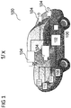
- FIG. 1 shows a vehicle 100 including a safety system 200 (see also FIG. 2 ) in accordance with various aspects of the present disclosure. It is appreciated that vehicle 100 and safety system 200 are exemplary in nature and may thus be simplified for explanatory purposes. Locations of elements and relational distances (as discussed above, the figures are not to scale) are provided as examples and are not limited thereto.
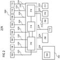
- the safety system 200 may include various components depending on the requirements of a particular implementation. As shown in FIG. 1 and FIG.
- the safety system 200 may include one or more processors 102, one or more image acquisition devices 104 such as, e.g., one or more cameras, one or more position sensors 106 such as a Global Navigation Satellite System (GNSS), e.g., a Global Positioning System (GPS), one or more memories 202, one or more map databases 204, one or more user interfaces 206 (such as, e.g., a display, a touch screen, a microphone, a loudspeaker, one or more buttons and/or switches, and the like), and one or more wireless transceivers 208, 210, 212.
- the wireless transceivers 208, 210, 212 may be configured according to different desired radio communication protocols or standards.
- a wireless transceiver e.g., a first wireless transceiver 208 may be configured in accordance with a Short Range mobile radio communication standard such as e.g. Bluetooth, Zigbee, and the like.
- a wireless transceiver e.g., a second wireless transceiver 210) may be configured in accordance with a Medium or Wide Range mobile radio communication standard such as e.g. a 3G (e.g. Universal Mobile Telecommunications System - UMTS), a 4G (e.g. Long Term Evolution - LTE), or a 5G mobile radio communication standard in accordance with corresponding 3GPP (3 rd Generation Partnership Project) standards.
- 3G e.g. Universal Mobile Telecommunications System - UMTS
- 4G e.g. Long Term Evolution - LTE
- 5G mobile radio communication standard in accordance with corresponding 3GPP (3 rd Generation Partnership Project) standards.
- a wireless transceiver (e.g., a third wireless transceiver 212) may be configured in accordance with a Wireless Local Area Network communication protocol or standard such as e.g. in accordance with IEEE 802.11 (e.g. 802.11, 802.11a, 802.11b, 802.11g, 802.11n, 802.11p, 802.11-12, 802.11ac, 802.11ad, 802.11ah, and the like).
- the one or more wireless transceivers 208, 210, 212 may be configured to transmit signals via an antenna system over an air interface.
- the one or more processors 102 may include an application processor 214, an image processor 216, a communication processor 218, or any other suitable processing device.
- image acquisition devices 104 may include any number of image acquisition devices and components depending on the requirements of a particular application.
- Image acquisition devices 104 may include one or more image capture devices (e.g., cameras, CCDs (charge coupling devices), or any other type of image sensor).
- the safety system 200 may also include a data interface communicatively connecting the one or more processors 102 to the one or more image acquisition devices 104.
- a first data interface may include any wired and/or wireless first link 220 or first links 220 for transmitting image data acquired by the one or more image acquisition devices 104 to the one or more processors 102, e.g., to the image processor 216.
- the memories 202 as well as the one or more user interfaces 206 may be coupled to each of the one or more processors 102, e.g., via a third data interface.
- the third data interface may include any wired and/or wireless third link 224 or third links 224.
- the position sensor 106 may be coupled to each of the one or more processors 102, e.g., via the third data interface.
- Each processor 214, 216, 218 of the one or more processors 102 may include various types of hardware-based processing devices.
- each processor 214, 216, 218 may include a microprocessor, pre-processors (such as an image pre-processor), graphics processors, a central processing unit (CPU), support circuits, digital signal processors, integrated circuits, memory, or any other types of devices suitable for running applications and for image processing and analysis.
- each processor 214, 216, 218 may include any type of single or multicore processor, mobile device microcontroller, central processing unit, etc.
- These processor types may each include multiple processing units with local memory and instruction sets.
- Such processors may include video inputs for receiving image data from multiple image sensors and may also include video out capabilities.
- processors 214, 216, 218 disclosed herein may be configured to perform certain functions in accordance with program instructions which may be stored in a memory of the one or more memories 202.
- a memory of the one or more memories 202 may store software that, when executed by a processor (e.g., by the one or more processors 102), controls the operation of the system, e.g., the safety system.
- a memory of the one or more memories 202 may store one or more databases and image processing software, as well as a trained system, such as a neural network, or a deep neural network, for example.
- the one or more memories 202 may include any number of random access memories, read only memories, flash memories, disk drives, optical storage, tape storage, removable storage and other types of storage.
- the safety system 200 may further include components such as a speed sensor 108 (e.g., a speedometer) for measuring a speed of the vehicle 100.
- the safety system may also include one or more accelerometers (either single axis or multiaxis) (not shown) for measuring accelerations of the vehicle 100 along one or more axes.
- the safety system 200 may further include additional sensors or different sensor types such as an ultrasonic sensor, a thermal sensor, one or more radar sensors 110, one or more LIDAR sensors 112 (which may be integrated in the head lamps of the vehicle 100), and the like.
- the radar sensors 110 and/or the LIDAR sensors 112 may be configured to provide pre-processed sensor data, such as radar target lists or LIDAR target lists.
- the third data interface may couple the speed sensor 108, the one or more radar sensors 110 and the one or more LIDAR sensors 112 to at least one of the one or more processors 102.
- the one or more memories 202 may store data, e.g., in a database or in any different format, that, e.g., indicate a location of known landmarks.
- the one or more processors 102 may process sensory information (such as images, radar signals, depth information from LIDAR or stereo processing of two or more images) of the environment of the vehicle 100 together with position information, such as a GPS coordinate, a vehicle's ego-motion, etc., to determine a current location of the vehicle 100 relative to the known landmarks, and refine the determination of the vehicle's location. Certain aspects of this technology may be included in a localization technology such as a mapping and routing model.
- the map database 204 may include any type of database storing (digital) map data for the vehicle 100, e.g., for the safety system 200.
- the map database 204 may include data relating to the position, in a reference coordinate system, of various items, including roads, water features, geographic features, businesses, points of interest, restaurants, gas stations, etc.
- the map database 204 may store not only the locations of such items, but also descriptors relating to those items, including, for example, names associated with any of the stored features.
- a processor of the one or more processors 102 may download information from the map database 204 over a wired or wireless data connection to a communication network (e.g., over a cellular network and/or the Internet, etc.).
- the map database 204 may store a sparse data model including polynomial representations of certain road features (e.g., lane markings) or target trajectories for the vehicle 100.
- the map database 204 may also include stored representations of various recognized landmarks that may be provided to determine or update a known position of the vehicle 100 with respect to a target trajectory.
- the landmark representations may include data fields such as landmark type, landmark location, among other potential identifiers.
- the safety system 200 may include a driving model, e.g., implemented in an advanced driving assistance system (ADAS) and/or a driving assistance and automated driving system.
- a driving model e.g., implemented in an advanced driving assistance system (ADAS) and/or a driving assistance and automated driving system.
- the safety system 200 may include (e.g., as part of the driving model) a computer implementation of a formal model such as a safety driving model.
- a safety driving model may be or include a mathematical model formalizing an interpretation of applicable laws, standards, policies, etc. that are applicable to self-driving (ground) vehicles.
- a safety driving model may be designed to achieve, e.g., three goals: first, the interpretation of the law should be sound in the sense that it complies with how humans interpret the law; second, the interpretation should lead to a useful driving policy, meaning it will lead to an agile driving policy rather than an overly-defensive driving which inevitably would confuse other human drivers and will block traffic and in turn limit the scalability of system deployment; and third, the interpretation should be efficiently verifiable in the sense that it can be rigorously proven that the self-driving (autonomous) vehicle correctly implements the interpretation of the law.
- a safety driving model may be or include a mathematical model for safety assurance that enables identification and performance of proper responses to dangerous situations such that self-perpetrated accidents can be avoided.
- a safety driving model may implement logic to apply driving behavior rules such as the following five rules:
- the vehicle 100 may include the safety system 200 as also described with reference to FIG. 2 .
- the vehicle 100 may include the one or more processors 102 e.g. integrated with or separate from an engine control unit (ECU) of the vehicle 100.
- ECU engine control unit
- the safety system 200 may in general generate data to control or assist to control the ECU and/or other components of the vehicle 100 to directly or indirectly control the driving of the vehicle 100.
- the one or more processors 102 of the vehicle 100 may implement the following aspects and methods.
- Safety Driving Modules may be considered formal, mathematical models for AV safety, which may be intended to be used as a safety model for AV decision making.
- Safety Driving Modules may include a set of rules, which are modeled through a set of mathematical equations that describe the physics of reasonable worst case driving situations involving other road users. Using these rule, the safety system can determine whether the current state of the AV is safe.
- Safety Driving Modules may recommend restrictions of the actuator control commands, said restrictions being selected to return the AV back to a safe state. Consequently, Safety Driving Modules can be used as an independent safety layer for the decision making components inside an AV stack.
- Safety Driving Modules may require a complete and correct environment model containing all objects with their locations, orientations and velocities in the environment of the ego vehicle. If any of these information is missing or incorrect, Safety Driving Modules may no longer be able to determine whether the vehicle behavior is safe. Therefore, it may be necessary to verify the correctness of the Safety Driving Module environment model input.
- Safety Driving Modules can be verified and corrected as needed. For example, should the monitor detect a missing object (e.g., by having grid occupancy but no corresponding object), the corresponding occupied grid cells can be used as independent objects. Using this data, Safety Driving Modules can evaluate potential conflicts among these cells and by that means avoid dangerous situations.
- Occupancy grids are a widely used method of modeling the environment of autonomous vehicles.
- occupancy grids divide the environment surrounding a vehicle into discrete grid cells.
- Each cell stores a stochastic state representation, where the state may be static occupied, dynamic occupied, free or unknown.
- the dynamic occupied cells may also provide information about the velocity of the current cell.
- One or more processors may estimate the dynamic occupancy grid based on information from one or more sensors (e.g., LIDAR information, Radar information, camera information, ultrasound information, etc.) by using particle filters.
- LIDAR information e.g., LIDAR information, Radar information, camera information, ultrasound information, etc.
- Emerging sensor technologies such as HD Radar or LIDAR may provide both location and velocity, thereby allowing the processors to derive the occupancy grid information directly from the sensor information.
- the one or more processors may combine the cell state from the previous time step with the current estimated state using the same combination rules. This approach may permit satisfactory determination of the freespace in cluttered and static environments.
- Dynamic occupancy grids may be low-level feature trackers that do not rely on complex object representation. Thus, dynamic occupancy grids may be able to fuse information without making assumptions about an underlying shape and model.
- AVs do not generally rely on dynamic occupancy grids alone for making driving decisions. This may owe, at least, to the fact that limited sensor information is used to fill the grid. For example, such grids do not generally include height information, and objects extracted only from grid information generally lack a proper classification. Thus, AVs often employ more sophisticated, AI-based perception systems to identify objects and make driving decisions based on the identified objects. Nevertheless, low level feature trackers like a dynamic occupancy grid, may function well as a monitor/recovery system in the event of error.
- Object identification systems may utilize information from the dynamic occupancy system and optionally from one or more other data sources (e.g., vehicle sensors such as LIDAR, radar, ultrasound, video, or any combination thereof) to identify one or more objects in a vicinity of the vehicle.
- Object identification may result in various failures or errors. Common errors include: false positives (e.g, a virtual object is identified where no corresponding object exists in the physical world); false negatives (no virtual object is identified despite a corresponding object existing in the physical world); error in velocity (object is associated with a velocity that does not correspond to a velocity of the detected object in the physical world; and error in position (detected object is attributed with an inaccurate position). Because errors in position are remedied by the strategies to address false positives and false negatives, as described herein, they will be addressed only with respect to false negatives and false positives.
- the environment model may include ghost objects that do not exist in the physical environment. Such false positives could lead to an unnecessary braking maneuver of the planning systems and therefore limit comfort or availability of the system. False Negatives may lead to a collision, since the planning systems would not generally be aware of the missing object, and thus cannot react properly. Errors in velocity may also lead to a collision, as the actual velocity of the object may not be properly considered.
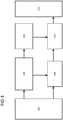
- FIG. 3 depicts a conventional AV system stack.
- the conventional AV system stack may include sensor layer 302, which may further include one or more diverse and/or redundant sensors (e.g. cameras, radar, LIDAR, or any combination thereof).
- the conventional AV system stack may further include a perception layer 304, which may extract from the sensor data object information for localization, object fusion, and/or tracking.
- the conventional AV system stack may further include a planning layer 306, that may use the resulting information, which may often be referred to as an environment model, to perform the steps required for decision making and trajectory generation.
- the conventional AV system stack may further include an Safety Driving Module 310, which may make driving decisions based on information received from the planning layer 306.
- the conventional AV system stack may further include one or more vehicle actuators 312, which may receive and implement driving commands from the Safety Driving Module layer.
- the AV system stack may implement AI-based approaches for the perception layer, as AIs are associated with increased performance over conventional algorithmic methods of object detection / extraction / tracking, etc.
- AI's excellent performance in this regard it may be very difficult to validate the AI's output with respect to objects. This may result at least from the fact that the AI evaluation is largely opaque.
- the procedures by which the AI evaluates sensor data and/or dynamic occupancy grid data to determine the presence or absence of objects may be essentially unknown.
- FIG. 4 shows a modified AV system stack, according to an aspect of the disclosure.
- the safety stack of FIG. 4 may include the sensor layer 302, the perception layer 304, the planning layer 306, the Safety Driving Module 310, and the one or more vehicle actuators 312.
- the modified AV stack of FIG. 4 may include a Safety Driving Module Input Validator 408, which may be configured to compare detected object data (e.g., existence or absence of an object, position, velocity, or any combination thereof), as described herein.
- the Safety Driving Module Input Validator 408 may receive information about detected objects, or information about an absence of a detected object, optionally along with object velocity information. As described herein, the Safety Driving Module Input Validator 408 may compare this received object information with cell information of a dynamic occupancy grid, including, but not limited to, occupancy probability information of one or more cells, and optionally velocity information. On the basis of these comparisons as described in greater detail herein, the Safety Driving Module Input Validator 408 may accept the detected object information, determine a false positive object detection to have occurred, determine a false negative object detection to have occurred, determine an incorrect velocity to have been detected, correct any of the previously listed detections, or any combination thereof.
- FIG. 5 discloses a safety driving module according to an aspect of the disclosure.
- the Safety Driving Module may include an input module 502, which may receive sensor information, which may then processed by the complex function (object extraction, tracking and fusion, i.e., perception) 504 and the monitor 506.
- the sensor information may be any sensor information whatsoever for detecting objects for an AV, including, but not limited to, image sensor data, LIDAR data, Radar data, ultrasound data, etc.
- the monitor 506 may include a dynamic occupancy grid combined with logic for checking.
- the monitor may compare object information with occupancy grid information (presence or absence of objects, detected object velocity, etc.), and if the monitor detects potential conflicts between these data, the recovery function module 508 may utilize the occupancy grid information to modify detected object information (place one or more new objects in an area were no object was detected, delete an object where an object was detected, change object velocity information, etc.).
- a switch 510 may direct either the output of the complex function (object information from the complex perception layer) or data from the recovery function to the Safety Driving Module.
- the switch 510 may be a physical switch or a logical switch.
- the switch 510 may be implemented as software.
- a safety concept may be required for both the software and the hardware.
- certain hardware solutions have been proposed, it is still an open question how to design a safety strategy for the software of an AD system. For example, if the perception filters out an object, this cannot be wholly detected by the underlying hardware. Hence, a dedicated safety strategy for the software layer may be required as well.
- a key challenge for such a software architecture may be that the monitor must be capable of detecting failures of the main channel (e.g. missing objects), while requiring significantly less computational complexity than the main channel. Therefore, a novel solution that uses a monitor-recovery approach with an occupancy grid for object perception is disclosed herein.
- Safety Driving Modules may establish a monitor & recovery for the decision making of an automated vehicle. Nevertheless, Safety Driving Modules rely on information that they receive. If there is an error in this information that the Safety Driving Module receives, the Safety Driving Module is unlikely to function correctly. In order to assure correct behavior of the Safety Driving Module, it may be desired to validate the Safety Driving Module input.
- Safety Driving Module input may include: map information; information about the ego vehicle, such as the position dimension and velocity and the route the vehicle wants to drive; environment model in an object representation; and object information.
- One or more processors may represent sensor data in a dynamic occupancy grid.
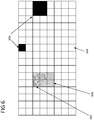
- FIG. 6 shows a dynamic occupancy grid, according to an aspect of the disclosure.
- the one or more processors may represent sensor data in any one or more of the occupancy grid cells.
- the one or more processors may designate the cells as being, for example, of unknown occupancy, of being dynamic occupied cells 604, static occupied cells 606, or free cells 608.
- Cells may be recorded as vectors, arrays, matrices, or in any other manner.
- Objects may be described by the state o consisting of the position x; y, velocity vx; vy, dimension as bounding box and/or variance ⁇ ( ⁇ ).
- the one or more processors may verify the validity of the object determination based on the dynamic occupancy grid. To perform this validation, the one or more processors may calculate the consistency and/or conflicts of the object position, the bounding box information and/or the variance with information in the occupancy grid. Based on these comparisons, the one or more processors may utilize one or more metrics and/or algorithms that permit the processors to determine whether the object detection represents a true positive or false positive.
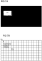
- FIGs 7A and 7B show a true positive object detection, according to an aspect of the disclosure.
- a detected object 702 is represented on a grid. That is, one or more processors, which may optionally include an AI, receive dynamic occupancy grid information and, at least on the basis of the dynamic occupancy grid information, determine the presence or absence of one or more objects.
- one or more objects are detected, they will ideally correspond to one or more cells of the dynamic occupancy grid that are determined to be occupied or have a high probability of being occupied.
- the absence of an object should correspond with one or more cells of the dynamic occupancy grid that are unoccupied or have a low probability of being occupied.
- FIG. 7B shows cells of the dynamic occupancy grid having data on which the object detection of FIG. 7A is based. Near the top, left portion of the dynamic occupancy grid, six cells 704 are indicated as being occupied. On the basis of the six cells, the one or more processors have detected an object, as shown in FIG. 7A . The one or more processors may be configured to compare the detected object with the occupied cells 704 of FIG. 7A , or vice versa, as will be discussed in greater detail. In this case, the locations of the occupied cells correspond closely with the location of the detected object. In FIG. 7B , a first row of three cells is indicated as being occupied, and a second of two cells is indicated as being occupied.
- FIGs. 8A and 8B show a false-positive, according to an aspect of the disclosure.
- object 802 is detected on the basis of one or more cells 804 in a dynamic occupancy grid 8A. It can be seen that the location of the detected object in FIG. 8A does not correspond closely to the locations of the occupied cells 804 in FIG. 8B .
- the occupied cells 804 in FIG. 8B may correspond to a sensor error, sensor noise, or otherwise. In this example, a significant difference between the location of the detected object in FIG. 8A and the locations of the occupied cells in FIG. 8B is present.
- the one or more processors may analyze this difference and, if the one or more processors determine that the difference is outside of a predetermined range, the one or more processors may deem the detected object of FIG. 8A to represent a false positive.
- FIGs. 9A and 9B show a false-negative, according to an aspect of the disclosure.
- the one or more processors include but not limited to an IA
- This negative detection is depicted in FIG 9A , in which no obstacle is shown as being present.
- FIG. 9B on which the detection of no obstacle is based, shows a plurality of occupied cells 902.
- the one or more processors may analyze the lack of a detected object for an area corresponding to the plurality of occupied cells 902, and if a difference between the lack of the detected object and the plurality of occupied cells is outside of a predetermined range, the one or more processors may determine the lack of a detected obstacle to be a false negative.
- the one or more processors may also utilize similar steps to evaluate determined object velocity.
- the one or more processors may compare the velocity distribution of the cells in an object region with the velocity distribution of the object using a comparing rule (e.g., a Bhattacharyya distance, an average, a standard deviation, or any combination thereof). That is, an object may include an associated velocity. Occupancy grid cells corresponding to an object's location may also include corresponding velocities, or velocities may be derivable from the cell data.
- a comparison of the object velocity and the cell velocities may be evaluated according to a comparing rule. Based on the results of this comparison, the velocity of the object may be confirmed, adjusted, or even deleted.
- the one or more processors may remove the object representing the false positive from the list of detected objects or otherwise deactivate the object.
- the one or more processors may be configured to delete the object from the object data.
- the one or more processors may be confirmed to place a tag within the object data, the tag representing an instruction to delete or disregard some or all of the object information.
- the one or more processors may recover the object position and velocity information from the dynamic occupancy cell information.
- the one or more processors may perform this in a simplistic manner by creating one object per cell, rather than an object representing multiple cells.
- the one or more processors may cluster a plurality of cells to derive a single object information out of the cluster.
- the one or more processors may recover velocity information using cell velocity information within the dynamic occupancy grid.
- AV safety models may utilize inputs including the states of all detected objects in an environment O.
- the one or more processors may convert an object track into a spatial occupancy.
- the one or more processors may first determine the region that is covered by the object at a given point in time (e.g., the current time).
- the one or more processors may determine region Ao by the state o and its covariance matrix ⁇ (o).
- the coverage function may be defined as c( ⁇ ; o) that will determine the coverage for a position ⁇ and a given object o.
- c ⁇ o ⁇ 1 , if ⁇ ⁇ A o 0 , if ⁇
- the occupancy grid may provide the spatial occupancy probability for a position ⁇ , which is denoted P( ⁇ ).
- the one or more processors can verify whether the environment model agrees or conflicts with the grid information. This can be understood as a procedure to verify true positive object detection; to correct false-positive object detection; to correct false negative-detected objects; and to correct velocity information.
- Safety Driving Modules generally expect a binary decision about whether an object exists.
- dynamic occupancy grids include occupancy probability information of a plurality of cells, and thus do not often provide binary object information, but rather occupancy probability of cells which may represent an object.
- the one or more processors may remove the object from the output sent to Safety Driving Module, as failure of the function indicates that the object represents a false positive.
- the one or more processors may exploit the conflict ⁇ . If a false negative occurs, there is a region of high conflict ⁇ . In order to recover from these false negatives, the one or more processors may create a new object for each cell with ⁇ > ⁇ fn , where ⁇ fn may be a user-defined parameter (for example, a parameter that permits tuning the sensitivity to False Negatives). In this way, the one or more processors may create a plurality of detected objects, wherein each of the plurality of detected objects represents a cell with a high probability of occupancy.
- This recovery strategy does not, however, recover object dimensions. That is, in the event that a single object in the physical world is represented by a plurality of detected objects whose sizes correspond to cells of the dynamic occupancy grid, the dimensions of the detected object in the physical world remain undetermined. However, the Safety Driving Modules only require dimensions of the objects to determine the closest point to the ego vehicle. As such detecting a plurality of objects whose sizes correspond to the sizes of cells in a dynamic occupancy grid provides sufficient information for a safe driving decision from the perspective of an Safety Driving Module.
- the one or more processors may define a second Boolean function f vel , as stated below, that can verify that the velocity is in an expected range.
- f vel ⁇ o ⁇ v ⁇ 1 , if d ⁇ o ⁇ ⁇ v 0 , if d ⁇ o ⁇ ⁇ v
- the recovery strategy employed may be similar to the False Negative recovery function.
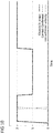
- FIG. 10 shows an analysis of the monitor's ability to validate correct information, according to an aspect of the disclosure.
- time is represented along the x-axis
- the number of objects is represented along the y-axis.
- the positions could be verified for all timestamps.
- the monitor was also able to verify the velocity information for most of the situations; however, occasionally the underlying dynamic occupancy grid algorithm failed to determine the dynamic belief for some objects, which was due to an inherent property in the dynamic grid implementation using particle filters. Hence, even with a more optimized implementation, these upsets can still occur under rare circumstances.
- the evaluation indicates that if the dynamic belief is too low, the monitor still can correctly validate the object position, and only the object velocity is flagged as uncertain. Consequently, the one or more processors can still use information of the object, and the overall system performance is not impacted.
- This figure indicates that, in tests of the model described herein, true positives were correctly classified 100% of the time.
- FIG. 11 shows comparison results with respect false positives, according to an aspect of the disclosure.
- a scenario was investigated in which no object was present the scene.
- a scenario was investigated in which one or more objects were present in the scene.
- the monitor occasionally failed to identify the False Positive. This was due to the fact that the randomly placed ghost object was generated at a position where an actual object was located. Although the positions matched in these cases, the velocity information often conflicted, and hence the monitor detected this issue. This can be remedied by checking objects for collision or overlap.
- FIG. 12 shows results of an analysis of false positives, according to an aspect of the disclosure.
- missed objects False Negatives
- all objects of the input to the environment model validation were first removed. Then for all the removed objects, it was determined whether the monitor was able to detect the missing objects and to create recovery objects. For this, the output of the validation was assessed to determine whether it contained objects that were within or in close proximity to the removed object.
- the quality of the recovered velocity information was analyzed. Therefore, the speed and orientation of the recovered were compared with the information of the original object. The results show that missing objects were identified immediately, while the recovery of velocity information could require slightly more time.
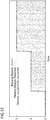
- FIG. 13 shows an evaluation of velocity errors, according to an aspect of the disclosure.
- a first scenario in which a pedestrian is crossing the street in front of the ego vehicle was utilized. Two tests were run. In the first test, an error of 0.5 radians was added to the heading of the pedestrian. In the second test, an error of 0.7 radians was added. Results show that for the first test, the error was detected most of the times, whereas for the second scenario, the error was always detected.
- FIG. 14 shows results of a Safety Driving Module analysis according to an aspect of the disclosure.
- a first group of groundtruth information known information about the position and/or velocity of obstacles relative to the ego vehicle
- a second group of corrected information using the principles and methods of recovery disclosed herein recovered obstacle information
- This chart indicates identical results of both categories, indicating that the Safety Driving Module operated identically using the ground truth information and the recovered information. This indicates that the recovered information can be safely used for AV operation.
- FIG. 15 shows an occupancy verification device, according to an aspect of the disclosure.
- the occupancy verification device may include one or more processors 1502, configured to receive occupancy grid data, representing a plurality of cells of an occupancy grid and for each cell of the plurality of cells, a probability of whether the cell is occupied; receive object location data, representing one or more locations of one or more objects identified using a model; map the object location data to one or more cells of the plurality of cells based on the one or more locations of the one or more objects; determine comparison grid data, representing the plurality of cells of the occupancy grid and for each cell of the plurality of cells, a probability of whether the cell is occupied based on whether the object location data are mapped to the cell; compare the occupancy grid data to the comparison grid data using at least one comparing rule; and output trust data representing a result of the comparison.
- FIG. 16 shows an occupancy verification device according to another aspect of the disclosure.
- the occupancy verification device may include one or more processors 1602, configured to receive occupancy grid data, representing occupancy a plurality of cells and for each cell of the plurality of cells, a probability of whether the cell is occupied; receive object vacancy data, representing one or more locations in which no object has been detected; map the object vacancy data to one or more cells of the plurality of cells based on the one or more locations in which no object is detected; determine comparison grid data, representing the plurality of cells and for each cell of the plurality of cells, a probability of whether the cell is occupied based on whether no objects represented by the object vacancy data are mapped to the cell; compare the occupancy grid data to the comparison grid data using at least one comparing rule; and output trust data representing a result of the comparison.
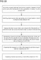
- FIG. 17 shows a method of occupancy verification according to an aspect of the disclosure, including receiving occupancy grid data, representing a plurality of cells of an occupancy grid and for each cell of the plurality of cells, a probability of whether the cell is occupied 1702; receiving object location data, representing one or more locations of one or more objects identified using a model 1704; mapping the object location data to one or more cells of the plurality of cells based on the one or more locations of the one or more objects 1706; determining comparison grid data, representing the plurality of cells of the occupancy grid and for each cell of the plurality of cells, a probability of whether the cell is occupied based on whether the object location data are mapped to the cell 1708; comparing the occupancy grid data to the comparison grid data using at least one comparing rule 1710; and outputting trust data representing a result of the comparison 1712.
- FIG. 18 shows a method of occupancy verification according to another aspect of the disclosure, including receiving occupancy grid data, representing occupancy a plurality of cells and for each cell of the plurality of cells, a probability of whether the cell is occupied 1802; receiving object vacancy data, representing one or more locations in which no object has been detected 1804; mapping the object vacancy data to one or more cells of the plurality of cells based on the one or more locations in which no object is detected 1806; determining comparison grid data, representing the plurality of cells and for each cell of the plurality of cells, a probability of whether the cell is occupied based on whether no objects represented by the object vacancy data are mapped to the cell 1808; comparing the occupancy grid data to the comparison grid data using at least one comparing rule 1810; and outputting trust data representing a result of the comparison 1812.
- the at least one comparing rule may include determining a distance between the occupancy grid data and the comparison grid data in accordance with a predefined distance metric.
- This predefined distance metric may include or be a Bhattacharyya distance between the occupancy grid data and the comparison grid data.
- the distance metric may be selected based on the given implementation.
- the distance metric may include determining an average distance and comparing the average distance to a predetermined range or comparing the average distance to a threshold defined as one or more standard deviations from the average.
- the one or more processors may include a tag as an instruction to deactivate the object.
- the object may be removed from one or more registers, arrays, matrices, vectors, or otherwise. The object may be deleted or ignored, such that it is not incorporated in a driving decision made by the Safety Driving Module.
- a device corresponding to a method detailed herein may include one or more components configured to perform each aspect of the related method.
Landscapes
- Engineering & Computer Science (AREA)
- Physics & Mathematics (AREA)
- Theoretical Computer Science (AREA)
- General Physics & Mathematics (AREA)
- Computer Vision & Pattern Recognition (AREA)
- Automation & Control Theory (AREA)
- Data Mining & Analysis (AREA)
- Multimedia (AREA)
- Evolutionary Computation (AREA)
- General Engineering & Computer Science (AREA)
- Software Systems (AREA)
- Artificial Intelligence (AREA)
- Aviation & Aerospace Engineering (AREA)
- Radar, Positioning & Navigation (AREA)
- Remote Sensing (AREA)
- Human Computer Interaction (AREA)
- Mechanical Engineering (AREA)
- Transportation (AREA)
- Mathematical Physics (AREA)
- Computing Systems (AREA)
- Life Sciences & Earth Sciences (AREA)
- Electromagnetism (AREA)
- General Health & Medical Sciences (AREA)
- Biophysics (AREA)
- Computational Linguistics (AREA)
- Biomedical Technology (AREA)
- Molecular Biology (AREA)
- Evolutionary Biology (AREA)
- Quality & Reliability (AREA)
- Health & Medical Sciences (AREA)
- Bioinformatics & Computational Biology (AREA)
- Bioinformatics & Cheminformatics (AREA)
- Medical Informatics (AREA)
- Traffic Control Systems (AREA)
Applications Claiming Priority (1)
| Application Number | Priority Date | Filing Date | Title |
|---|---|---|---|
| US16/912,758 US20200326721A1 (en) | 2020-06-26 | 2020-06-26 | Occupancy verification device and method |
Publications (1)
| Publication Number | Publication Date |
|---|---|
| EP3929802A1 true EP3929802A1 (en) | 2021-12-29 |
Family
ID=72747814
Family Applications (1)
| Application Number | Title | Priority Date | Filing Date |
|---|---|---|---|
| EP20207113.0A Pending EP3929802A1 (en) | 2020-06-26 | 2020-11-12 | An occupancy verification device and method |
Country Status (3)
| Country | Link |
|---|---|
| US (1) | US20200326721A1 (zh) |
| EP (1) | EP3929802A1 (zh) |
| CN (1) | CN113850391A (zh) |
Families Citing this family (4)
| Publication number | Priority date | Publication date | Assignee | Title |
|---|---|---|---|---|
| JP7397609B2 (ja) * | 2019-09-24 | 2023-12-13 | 株式会社Subaru | 走行環境認識装置 |
| FR3116640B1 (fr) * | 2020-11-20 | 2023-11-17 | Commissariat Energie Atomique | Procédé itératif d’estimation du mouvement d’un corps matériel par génération d’une grille de mouvement filtrée |
| US11618453B2 (en) * | 2021-02-23 | 2023-04-04 | Aptiv Technologies Limited | Grid-based road model with multiple layers |
| CN113093221A (zh) * | 2021-03-31 | 2021-07-09 | 东软睿驰汽车技术(沈阳)有限公司 | 占据栅格地图的生成方法及装置 |
Citations (3)
| Publication number | Priority date | Publication date | Assignee | Title |
|---|---|---|---|---|
| US20150073707A1 (en) * | 2013-09-09 | 2015-03-12 | Honeywell International Inc. | Systems and methods for comparing range data with evidence grids |
| US20180300561A1 (en) * | 2017-04-13 | 2018-10-18 | Bayerische Motoren Werke Aktiengesellschaft | Method for Detecting and/or Tracking Objects |
| US20190226854A1 (en) * | 2019-03-29 | 2019-07-25 | Intel Corporation | Methods and systems for improving maps |
Family Cites Families (26)
| Publication number | Priority date | Publication date | Assignee | Title |
|---|---|---|---|---|
| US9683854B2 (en) * | 2009-07-19 | 2017-06-20 | Aaron T. Emigh | Pricing by historical comparison |
| US9990548B2 (en) * | 2016-03-09 | 2018-06-05 | Uber Technologies, Inc. | Traffic signal analysis system |
| WO2018125938A1 (en) * | 2016-12-30 | 2018-07-05 | DeepMap Inc. | Enrichment of point cloud data for high-definition maps for autonomous vehicles |
| US10782693B2 (en) * | 2017-09-07 | 2020-09-22 | Tusimple, Inc. | Prediction-based system and method for trajectory planning of autonomous vehicles |
| JP7346401B2 (ja) * | 2017-11-10 | 2023-09-19 | エヌビディア コーポレーション | 安全で信頼できる自動運転車両のためのシステム及び方法 |
| DE102018200683A1 (de) * | 2018-01-17 | 2019-07-18 | Bayerische Motoren Werke Aktiengesellschaft | Verfahren zur Detektion eines Objektes |
| US11501105B2 (en) * | 2018-03-02 | 2022-11-15 | Zoox, Inc. | Automatic creation and updating of maps |
| US11093759B2 (en) * | 2018-03-06 | 2021-08-17 | Here Global B.V. | Automatic identification of roadside objects for localization |
| US11340079B1 (en) * | 2018-05-21 | 2022-05-24 | AI Incorporated | Simultaneous collaboration, localization, and mapping |
| US11048265B2 (en) * | 2018-06-18 | 2021-06-29 | Zoox, Inc. | Occlusion aware planning |
| US11592818B2 (en) * | 2018-06-20 | 2023-02-28 | Zoox, Inc. | Restricted multi-scale inference for machine learning |
| US11353577B2 (en) * | 2018-09-28 | 2022-06-07 | Zoox, Inc. | Radar spatial estimation |
| CN111307166B (zh) * | 2018-12-11 | 2023-10-03 | 北京图森智途科技有限公司 | 一种构建占据栅格地图的方法及其装置、处理设备 |
| WO2020131399A1 (en) * | 2018-12-18 | 2020-06-25 | Aptiv Technologies Limited | Operation of a vehicle using motion planning with machine learning |
| US11170299B2 (en) * | 2018-12-28 | 2021-11-09 | Nvidia Corporation | Distance estimation to objects and free-space boundaries in autonomous machine applications |
| WO2020146447A1 (en) * | 2019-01-08 | 2020-07-16 | Aptiv Technologies Limited | Field theory based perception for autonomous vehicles |
| US11364936B2 (en) * | 2019-02-28 | 2022-06-21 | Huawei Technologies Co., Ltd. | Method and system for controlling safety of ego and social objects |
| US11016492B2 (en) * | 2019-02-28 | 2021-05-25 | Zoox, Inc. | Determining occupancy of occluded regions |
| JP7371111B2 (ja) * | 2019-03-05 | 2023-10-30 | エヌビディア コーポレーション | 自律走行車のナビゲーション用高精度地図を生成するためのポーズグラフの分散処理 |
| WO2020185779A1 (en) * | 2019-03-11 | 2020-09-17 | Nvidia Corporation | Intersection detection and classification in autonomous machine applications |
| US11126180B1 (en) * | 2019-04-30 | 2021-09-21 | Zoox, Inc. | Predicting an occupancy associated with occluded region |
| US11531346B2 (en) * | 2019-07-05 | 2022-12-20 | Uatc, Llc | Goal-directed occupancy prediction for autonomous driving |
| US11435946B2 (en) * | 2019-09-05 | 2022-09-06 | Micron Technology, Inc. | Intelligent wear leveling with reduced write-amplification for data storage devices configured on autonomous vehicles |
| US11577722B1 (en) * | 2019-09-30 | 2023-02-14 | Zoox, Inc. | Hyper planning based on object and/or region |
| US11827214B2 (en) * | 2020-03-05 | 2023-11-28 | Huawei Technologies Co., Ltd. | Machine-learning based system for path and/or motion planning and method of training the same |
| US11485384B2 (en) * | 2020-05-11 | 2022-11-01 | Zoox, Inc. | Unstructured vehicle path planner |
-
2020
- 2020-06-26 US US16/912,758 patent/US20200326721A1/en active Pending
- 2020-11-12 EP EP20207113.0A patent/EP3929802A1/en active Pending
- 2020-12-23 CN CN202011534118.4A patent/CN113850391A/zh active Pending
Patent Citations (3)
| Publication number | Priority date | Publication date | Assignee | Title |
|---|---|---|---|---|
| US20150073707A1 (en) * | 2013-09-09 | 2015-03-12 | Honeywell International Inc. | Systems and methods for comparing range data with evidence grids |
| US20180300561A1 (en) * | 2017-04-13 | 2018-10-18 | Bayerische Motoren Werke Aktiengesellschaft | Method for Detecting and/or Tracking Objects |
| US20190226854A1 (en) * | 2019-03-29 | 2019-07-25 | Intel Corporation | Methods and systems for improving maps |
Also Published As
| Publication number | Publication date |
|---|---|
| US20200326721A1 (en) | 2020-10-15 |
| CN113850391A (zh) | 2021-12-28 |
Similar Documents
| Publication | Publication Date | Title |
|---|---|---|
| EP3929802A1 (en) | An occupancy verification device and method | |
| EP3974270A1 (en) | Device for determining safety state of a vehicle | |
| US11947357B2 (en) | Controller for an autonomous vehicle, and network component | |
| CN112166304B (zh) | 传感器数据的误差检测 | |
| US20230174065A1 (en) | Methods and devices for triggering vehicular actions based on passenger actions | |
| US10627823B1 (en) | Method and device for performing multiple agent sensor fusion in cooperative driving based on reinforcement learning | |
| US11042156B2 (en) | System and method for learning and executing naturalistic driving behavior | |
| US20210309261A1 (en) | Driver and environment monitoring to predict human driving maneuvers and reduce human driving errors | |
| WO2020264010A1 (en) | Low variance region detection for improved detection | |
| US11610078B2 (en) | Low variance region detection for improved high variance region detection using machine learning | |
| US11605236B2 (en) | Training a machine-learned model to detect low variance regions | |
| US11188766B2 (en) | System and method for providing context aware road-user importance estimation | |
| Friji et al. | A dqn-based autonomous car-following framework using rgb-d frames | |
| US11657635B2 (en) | Measuring confidence in deep neural networks | |
| EP4201776A2 (en) | Driver scoring system and method using optimum path deviation | |
| US11983918B2 (en) | Platform for perception system development for automated driving system | |
| US20220114458A1 (en) | Multimodal automatic mapping of sensing defects to task-specific error measurement | |
| KR102350197B1 (ko) | 주행경로 설정장치 및 주행경로 설정방법 | |
| EP4220581A1 (en) | Estimation of risk exposure for autonomous vehicles | |
| EP4219262A1 (en) | In-vehicle system for estimation of risk exposure for an autonomous vehicle | |
| CN114217601B (zh) | 自驾车的混合决策方法及其系统 | |
| US11462020B2 (en) | Temporal CNN rear impact alert system | |
| EP4156043A1 (en) | Driver scoring system and method with accident proneness filtering using alert clustering and safety-warning based road classification | |
| US20220003556A1 (en) | Driver scoring system and method with driving event context normalization using road quality information | |
| EP4219261A1 (en) | Estimation of risk exposure for autonomous vehicles |
Legal Events
| Date | Code | Title | Description |
|---|---|---|---|
| PUAI | Public reference made under article 153(3) epc to a published international application that has entered the european phase |
Free format text: ORIGINAL CODE: 0009012 |
|
| STAA | Information on the status of an ep patent application or granted ep patent |
Free format text: STATUS: THE APPLICATION HAS BEEN PUBLISHED |
|
| AK | Designated contracting states |
Kind code of ref document: A1 Designated state(s): AL AT BE BG CH CY CZ DE DK EE ES FI FR GB GR HR HU IE IS IT LI LT LU LV MC MK MT NL NO PL PT RO RS SE SI SK SM TR |
|
| B565 | Issuance of search results under rule 164(2) epc |
Effective date: 20210409 |
|
| STAA | Information on the status of an ep patent application or granted ep patent |
Free format text: STATUS: REQUEST FOR EXAMINATION WAS MADE |
|
| 17P | Request for examination filed |
Effective date: 20220617 |
|
| RBV | Designated contracting states (corrected) |
Designated state(s): AL AT BE BG CH CY CZ DE DK EE ES FI FR GB GR HR HU IE IS IT LI LT LU LV MC MK MT NL NO PL PT RO RS SE SI SK SM TR |
|
| STAA | Information on the status of an ep patent application or granted ep patent |
Free format text: STATUS: EXAMINATION IS IN PROGRESS |
|
| 17Q | First examination report despatched |
Effective date: 20230901 |