EP3929663A1 - Image forming device - Google Patents
Image forming device Download PDFInfo
- Publication number
- EP3929663A1 EP3929663A1 EP19916127.4A EP19916127A EP3929663A1 EP 3929663 A1 EP3929663 A1 EP 3929663A1 EP 19916127 A EP19916127 A EP 19916127A EP 3929663 A1 EP3929663 A1 EP 3929663A1
- Authority
- EP
- European Patent Office
- Prior art keywords
- recording medium
- sheet member
- unit
- image forming
- preheating unit
- Prior art date
- Legal status (The legal status is an assumption and is not a legal conclusion. Google has not performed a legal analysis and makes no representation as to the accuracy of the status listed.)
- Granted
Links
Images





Classifications
-
- G—PHYSICS
- G03—PHOTOGRAPHY; CINEMATOGRAPHY; ANALOGOUS TECHNIQUES USING WAVES OTHER THAN OPTICAL WAVES; ELECTROGRAPHY; HOLOGRAPHY
- G03G—ELECTROGRAPHY; ELECTROPHOTOGRAPHY; MAGNETOGRAPHY
- G03G15/00—Apparatus for electrographic processes using a charge pattern
- G03G15/22—Apparatus for electrographic processes using a charge pattern involving the combination of more than one step according to groups G03G13/02 - G03G13/20
- G03G15/23—Apparatus for electrographic processes using a charge pattern involving the combination of more than one step according to groups G03G13/02 - G03G13/20 specially adapted for copying both sides of an original or for copying on both sides of a recording or image-receiving material
- G03G15/231—Arrangements for copying on both sides of a recording or image-receiving material
- G03G15/232—Arrangements for copying on both sides of a recording or image-receiving material using a single reusable electrographic recording member
- G03G15/234—Arrangements for copying on both sides of a recording or image-receiving material using a single reusable electrographic recording member by inverting and refeeding the image receiving material with an image on one face to the recording member to transfer a second image on its second face, e.g. by using a duplex tray; Details of duplex trays or inverters
- G03G15/235—Arrangements for copying on both sides of a recording or image-receiving material using a single reusable electrographic recording member by inverting and refeeding the image receiving material with an image on one face to the recording member to transfer a second image on its second face, e.g. by using a duplex tray; Details of duplex trays or inverters the image receiving member being preconditioned before transferring the second image, e.g. decurled, or the second image being formed with different operating parameters, e.g. a different fixing temperature
-
- G—PHYSICS
- G03—PHOTOGRAPHY; CINEMATOGRAPHY; ANALOGOUS TECHNIQUES USING WAVES OTHER THAN OPTICAL WAVES; ELECTROGRAPHY; HOLOGRAPHY
- G03G—ELECTROGRAPHY; ELECTROPHOTOGRAPHY; MAGNETOGRAPHY
- G03G15/00—Apparatus for electrographic processes using a charge pattern
- G03G15/20—Apparatus for electrographic processes using a charge pattern for fixing, e.g. by using heat
-
- B—PERFORMING OPERATIONS; TRANSPORTING
- B65—CONVEYING; PACKING; STORING; HANDLING THIN OR FILAMENTARY MATERIAL
- B65H—HANDLING THIN OR FILAMENTARY MATERIAL, e.g. SHEETS, WEBS, CABLES
- B65H5/00—Feeding articles separated from piles; Feeding articles to machines
- B65H5/08—Feeding articles separated from piles; Feeding articles to machines by grippers, e.g. suction grippers
-
- B—PERFORMING OPERATIONS; TRANSPORTING
- B65—CONVEYING; PACKING; STORING; HANDLING THIN OR FILAMENTARY MATERIAL
- B65H—HANDLING THIN OR FILAMENTARY MATERIAL, e.g. SHEETS, WEBS, CABLES
- B65H85/00—Recirculating articles, i.e. feeding each article to, and delivering it from, the same machine work-station more than once
-
- G—PHYSICS
- G03—PHOTOGRAPHY; CINEMATOGRAPHY; ANALOGOUS TECHNIQUES USING WAVES OTHER THAN OPTICAL WAVES; ELECTROGRAPHY; HOLOGRAPHY
- G03G—ELECTROGRAPHY; ELECTROPHOTOGRAPHY; MAGNETOGRAPHY
- G03G15/00—Apparatus for electrographic processes using a charge pattern
- G03G15/20—Apparatus for electrographic processes using a charge pattern for fixing, e.g. by using heat
- G03G15/2003—Apparatus for electrographic processes using a charge pattern for fixing, e.g. by using heat using heat
- G03G15/2007—Apparatus for electrographic processes using a charge pattern for fixing, e.g. by using heat using heat using radiant heat, e.g. infrared lamps, microwave heaters
-
- G—PHYSICS
- G03—PHOTOGRAPHY; CINEMATOGRAPHY; ANALOGOUS TECHNIQUES USING WAVES OTHER THAN OPTICAL WAVES; ELECTROGRAPHY; HOLOGRAPHY
- G03G—ELECTROGRAPHY; ELECTROPHOTOGRAPHY; MAGNETOGRAPHY
- G03G15/00—Apparatus for electrographic processes using a charge pattern
- G03G15/20—Apparatus for electrographic processes using a charge pattern for fixing, e.g. by using heat
- G03G15/2003—Apparatus for electrographic processes using a charge pattern for fixing, e.g. by using heat using heat
- G03G15/2014—Apparatus for electrographic processes using a charge pattern for fixing, e.g. by using heat using heat using contact heat
- G03G15/2017—Structural details of the fixing unit in general, e.g. cooling means, heat shielding means
- G03G15/2021—Plurality of separate fixing and/or cooling areas or units, two step fixing
-
- G—PHYSICS
- G03—PHOTOGRAPHY; CINEMATOGRAPHY; ANALOGOUS TECHNIQUES USING WAVES OTHER THAN OPTICAL WAVES; ELECTROGRAPHY; HOLOGRAPHY
- G03G—ELECTROGRAPHY; ELECTROPHOTOGRAPHY; MAGNETOGRAPHY
- G03G15/00—Apparatus for electrographic processes using a charge pattern
- G03G15/20—Apparatus for electrographic processes using a charge pattern for fixing, e.g. by using heat
- G03G15/2003—Apparatus for electrographic processes using a charge pattern for fixing, e.g. by using heat using heat
- G03G15/2014—Apparatus for electrographic processes using a charge pattern for fixing, e.g. by using heat using heat using contact heat
- G03G15/2039—Apparatus for electrographic processes using a charge pattern for fixing, e.g. by using heat using heat using contact heat with means for controlling the fixing temperature
-
- G—PHYSICS
- G03—PHOTOGRAPHY; CINEMATOGRAPHY; ANALOGOUS TECHNIQUES USING WAVES OTHER THAN OPTICAL WAVES; ELECTROGRAPHY; HOLOGRAPHY
- G03G—ELECTROGRAPHY; ELECTROPHOTOGRAPHY; MAGNETOGRAPHY
- G03G15/00—Apparatus for electrographic processes using a charge pattern
- G03G15/20—Apparatus for electrographic processes using a charge pattern for fixing, e.g. by using heat
- G03G15/2003—Apparatus for electrographic processes using a charge pattern for fixing, e.g. by using heat using heat
- G03G15/2014—Apparatus for electrographic processes using a charge pattern for fixing, e.g. by using heat using heat using contact heat
- G03G15/2053—Structural details of heat elements, e.g. structure of roller or belt, eddy current, induction heating
-
- G—PHYSICS
- G03—PHOTOGRAPHY; CINEMATOGRAPHY; ANALOGOUS TECHNIQUES USING WAVES OTHER THAN OPTICAL WAVES; ELECTROGRAPHY; HOLOGRAPHY
- G03G—ELECTROGRAPHY; ELECTROPHOTOGRAPHY; MAGNETOGRAPHY
- G03G15/00—Apparatus for electrographic processes using a charge pattern
- G03G15/50—Machine control of apparatus for electrographic processes using a charge pattern, e.g. regulating differents parts of the machine, multimode copiers, microprocessor control
- G03G15/5054—Machine control of apparatus for electrographic processes using a charge pattern, e.g. regulating differents parts of the machine, multimode copiers, microprocessor control by measuring the characteristics of an intermediate image carrying member or the characteristics of an image on an intermediate image carrying member, e.g. intermediate transfer belt or drum, conveyor belt
-
- G—PHYSICS
- G03—PHOTOGRAPHY; CINEMATOGRAPHY; ANALOGOUS TECHNIQUES USING WAVES OTHER THAN OPTICAL WAVES; ELECTROGRAPHY; HOLOGRAPHY
- G03G—ELECTROGRAPHY; ELECTROPHOTOGRAPHY; MAGNETOGRAPHY
- G03G15/00—Apparatus for electrographic processes using a charge pattern
- G03G15/60—Apparatus which relate to the handling of originals
- G03G15/602—Apparatus which relate to the handling of originals for transporting
-
- G—PHYSICS
- G03—PHOTOGRAPHY; CINEMATOGRAPHY; ANALOGOUS TECHNIQUES USING WAVES OTHER THAN OPTICAL WAVES; ELECTROGRAPHY; HOLOGRAPHY
- G03G—ELECTROGRAPHY; ELECTROPHOTOGRAPHY; MAGNETOGRAPHY
- G03G15/00—Apparatus for electrographic processes using a charge pattern
- G03G15/60—Apparatus which relate to the handling of originals
- G03G15/607—Apparatus which relate to the handling of originals for detecting size, presence or position of original
-
- G—PHYSICS
- G03—PHOTOGRAPHY; CINEMATOGRAPHY; ANALOGOUS TECHNIQUES USING WAVES OTHER THAN OPTICAL WAVES; ELECTROGRAPHY; HOLOGRAPHY
- G03G—ELECTROGRAPHY; ELECTROPHOTOGRAPHY; MAGNETOGRAPHY
- G03G15/00—Apparatus for electrographic processes using a charge pattern
- G03G15/65—Apparatus which relate to the handling of copy material
- G03G15/6555—Handling of sheet copy material taking place in a specific part of the copy material feeding path
- G03G15/6558—Feeding path after the copy sheet preparation and up to the transfer point, e.g. registering; Deskewing; Correct timing of sheet feeding to the transfer point
-
- G—PHYSICS
- G03—PHOTOGRAPHY; CINEMATOGRAPHY; ANALOGOUS TECHNIQUES USING WAVES OTHER THAN OPTICAL WAVES; ELECTROGRAPHY; HOLOGRAPHY
- G03G—ELECTROGRAPHY; ELECTROPHOTOGRAPHY; MAGNETOGRAPHY
- G03G21/00—Arrangements not provided for by groups G03G13/00 - G03G19/00, e.g. cleaning, elimination of residual charge
- G03G21/20—Humidity or temperature control also ozone evacuation; Internal apparatus environment control
- G03G21/206—Conducting air through the machine, e.g. for cooling, filtering, removing gases like ozone
-
- G—PHYSICS
- G03—PHOTOGRAPHY; CINEMATOGRAPHY; ANALOGOUS TECHNIQUES USING WAVES OTHER THAN OPTICAL WAVES; ELECTROGRAPHY; HOLOGRAPHY
- G03G—ELECTROGRAPHY; ELECTROPHOTOGRAPHY; MAGNETOGRAPHY
- G03G2215/00—Apparatus for electrophotographic processes
- G03G2215/16—Transferring device, details
- G03G2215/1666—Preconditioning of copy medium before the transfer point
- G03G2215/1671—Preheating the copy medium before the transfer point
Definitions
- the present invention relates to an image forming device.
- An electrophotographic system disclosed in Patent Literature 1 sets a printing speed used in a case where plural electrophotographic devices are connected to perform printing and a printing speed used in a case where plural electrophotographic devices are made independent of each other and printing is performed by separate electrophotographic devices, and includes a printing speed switching unit that switches between the printing speeds.
- Patent Literature 1 JP-H08-50429
- the toner image when forming a toner image on both surfaces of a recording medium, the toner image is first transferred onto a first surface of the recording medium.
- a preheating unit heats the recording medium having the toner image transferred onto the first surface thereof.
- a main heating unit comes into contact with the recording medium to heat the recording medium, and fixes the toner image onto the first surface of the recording medium heated by the preheating unit.
- the toner image is transferred onto a second surface of the recording medium having the toner image fixed onto the first surface thereof.
- the preheating unit heats the recording medium having the toner image transferred onto the second surface thereof.
- the main heating unit comes into contact with the recording medium to heat the recording medium, and fixes the toner image onto the second surface of the recording medium heated by the preheating unit.
- An object of the present invention is to reduce the difference between the glossiness of the toner image on the first surface and the glossiness of the toner image on the second surface, as compared with the case where, before the main heating unit heats the recording medium having the toner image transferred onto the second surface thereof, the temperature of the first surface of the recording medium is equal to or higher than the softening point of the toner since the recording medium having the toner image transferred onto the second surface thereof is heat by the preheating unit.
- An image forming device is characterized by including: a transfer unit that transfers a toner image onto a recording medium being conveyed; a main heating unit that is arranged downstream of the transfer unit in a conveyance direction of the recording medium, comes into contact with the recording medium to heat the recording medium, and fixes the toner image onto the recording medium; a reversing unit that reverses front and back of the recording medium having an image fixed onto a first surface of the recording medium by the main heating unit, and sends the recording medium to the transfer unit; and a preheating unit that is arranged between the transfer unit and the main heating unit in the conveyance direction of the recording medium and heats the recording medium having an image transferred onto a second surface of the recording medium, the preheating unit heating the recording medium so that a temperature of the first surface of the recording medium is lower than a softening point of a toner before the recording medium is heated by the main heating unit.
- An image forming device is characterized by that, in the image forming device according to the first aspect, the preheating unit heats the recording medium from a side of an unfixed toner image in a non-contact state.
- An image forming device is characterized by that, in the image forming device according to the second aspect, the recording medium is conveyed with a recording surface facing in a vertical direction when the preheating unit heats the recording medium having an image transferred onto the second surface, the preheating unit heats a recording member from above the recording member, and a blowing unit that blows air to the recording medium is provided on an opposite side of the recording medium being conveyed than the preheating unit.
- An image forming device is characterized by that, in the image forming device according to any one of the first to third aspects, a conveying unit that grips a leading end portion of the recording medium and conveys the recording medium is included, and, when the preheating unit heats the recording medium having an image transferred onto the second surface, the conveying unit conveys the recording medium with an image forming region on the first surface of the recording medium being in a non-contact state with another member.
- An image forming device is characterized by that, in the image forming device according to the fourth aspect, the conveying unit conveys the recording medium with a recording surface facing in a vertical direction when the preheating unit heats the recording medium having an image transferred onto the second surface, the preheating unit heats a recording member from above the recording member, and a stabilizing unit that stabilizes a conveyance posture of the recording member is arranged on a side opposite to the preheating unit on an opposite side of the recording medium being conveyed than the preheating unit in a non-contact state with the recording medium.
- a difference between glossiness of the toner image on the first surface and glossiness of the toner image on the second surface may be reduced as compared with a case where, before the main heating unit heats the recording medium, the temperature of the first surface of the recording medium is equal to or higher than the softening point of the toner since the preheating unit heats the recording medium having the toner image transferred onto the second surface thereof.
- a temperature of the second surface of the recording medium onto which an unfixed toner image is transferred may be made higher than the temperature of the first surface of the recording medium onto which a toner image is fixed.
- the preheating unit heats the recording medium having the image transferred onto the second surface thereof, the temperature of the first surface may be easily made lower than the softening point of the toner as compared with a case where air on the first surface side is stagnant.
- the preheating unit heats the recording medium having the image transferred onto the second surface thereof, it is possible to suppress deterioration in quality of the toner image formed on the first surface of the recording medium as compared with a case where the image forming region on the first surface of the recording medium comes into contact with another member.
- the image forming device of the fifth aspect of the present invention as compared with a case where the recording medium is conveyed in a state of being bent by gravity, it is possible to suppress, in one recording medium, occurrence of a difference in glossiness in the recording medium heated by the preheating unit.
- an arrow H indicates a device vertical direction (perpendicular direction)
- an arrow W indicates a device width direction (horizontal direction)
- an arrow D indicates a device depth direction (horizontal direction).
- An image forming device 10 is an electrophotographic image forming device that forms a toner image on a sheet member P.
- the image forming device 10 includes a control unit 160, an accommodating portion 50, a discharge portion 52, an image forming unit 12, a conveying mechanism 60, a reversing mechanism 80, a fixing device 100, and a cooling unit 90.
- the control unit 160 is configured with a central processing unit (CPU), a read only memory (ROM), a random access memory (RAM), and a hard disk drive (HDD) (none is shown).
- the CPU executes a processing program.
- the ROM stores various programs, various tables, parameters, and the like.
- the RAM is used as a work area or the like when the CPU executes various programs.
- the accommodating portion 50 has a function of accommodating the sheet member P as a recording medium.
- the image forming device 10 may include plural (for example, two) accommodating portions 50, and may selectively send out the sheet member P from the plural accommodating portions 50.
- the discharge portion 52 is a portion from which the sheet member P on which a toner image is formed is discharged. Specifically, after the toner image is fixed by the fixing device 100, the sheet member P cooled by the cooling unit 90 is discharged to the discharge portion 52.
- the image forming unit 12 has a function of forming a toner image on the sheet member P by an electrophotographic method.
- the image forming unit 12 includes a toner image forming unit 20 that forms a toner image, and a transfer device 30 that transfers the toner image formed by the toner image forming unit 20 to the sheet member P.
- the image forming device 10 includes toner image forming units 20 of a total of four colors of yellow (Y), magenta (M), cyan (C), and black (K).
- the (Y), (M), (C), and (K) shown in Fig. 9 show constituent portions corresponding to the respective colors.
- the toner image forming units 20 of these colors have basically the same configuration except for toner to be used.
- the toner image forming unit 20 of each color includes a photosensitive drum 21 (photoconductor) that rotates in a direction indicated by an arrow A in Fig. 8 , and a charger 22 that charges the photosensitive drum 21.
- the toner image forming unit 20 of each color includes an exposure device 23 that exposes the photosensitive drum 21 charged by the charger 22 to light to form an electrostatic latent image on the photosensitive drum 21, and a developing device 24 that uses toner to develop the electrostatic latent image, which is formed on the photosensitive drum 21 by the exposure device 23, so as to form a toner image.
- the transfer device 30 has a function of primarily transferring toner images of the photosensitive drums 21 of the respective colors onto an intermediate transfer body in a superimposed manner, and secondarily transferring the superimposed toner images onto the sheet member P.
- the transfer device 30 includes a transfer belt 31 as the intermediate transfer body, a primary transfer roll 33, and a transfer unit 35.
- the primary transfer roll 33 has a function of transferring a toner image formed on the photosensitive drum 21 to the transfer belt 31 at a primary transfer position T (see Fig. 8 ) between the photosensitive drum 21 and the primary transfer roll 33.
- the transfer belt 31 has an endless shape, and is wound around plural rolls 32 to determine a posture thereof. When at least one of the plural rolls 32 is driven to rotate, the transfer belt 31 rotates in a direction indicated by an arrow B, and conveys the primarily transferred toner image to a secondary transfer position NT to be described later.
- the transfer unit 35 has a function of transferring the toner image, which is transferred onto the transfer belt 31, to the sheet member P.
- the transfer unit 35 includes a secondary transfer unit 34 and a facing roll 36.
- the facing roll 36 is disposed below the transfer belt 31 so as to face the transfer belt 31.
- the secondary transfer unit 34 is disposed on an inner side of the transfer belt 31 such that the transfer belt 31 is disposed between the secondary transfer unit 34 and the facing roll 36.
- the secondary transfer unit 34 is configured with a corotron.
- the transfer unit 35 the toner image transferred onto the transfer belt 31 is transferred onto the sheet member P passing through the secondary transfer position NT by a electrostatic force generated due to electricity-discharge of the secondary transfer unit 34.
- the secondary transfer position NT is a position where the transfer belt 31 and the facing roll 36 are in contact with each other.
- the conveying mechanism 60 has a function of conveying the sheet member P accommodated in the accommodating portion 50 to the secondary transfer position NT. Further, the conveying mechanism 60 has a function of conveying the sheet member P from the secondary transfer position NT to the main heating unit 120 to be described later. The conveying mechanism 60 will be described in detail later.
- the reversing mechanism 80 has a function of reversing the front and back of the sheet member P.
- the reversing mechanism 80 will be described in detail later.
- the fixing device 100 has a function of fixing the toner image, which is transferred onto the sheet member P by the transfer device 30, onto the sheet member P.
- the fixing device 100 will be described in detail later.
- the cooling unit 90 has a function of cooling the sheet member P heated by the fixing device 100. As illustrated in Fig. 9 , the cooling unit 90 is disposed downstream of the main heating unit 120 of the fixing device 100 in a conveyance direction of the sheet member P.
- the cooling unit 90 includes two cooling rolls 92 arranged in the device width direction. Since the two cooling rolls 92 have the same configuration, one of the cooling rolls 92 will be described.
- the cooling roll 92 includes a pair of rolls 92a and 92b that sandwich the sheet member P in a conveyance path thereof.
- the roll 92a is disposed above the conveyance path of the sheet member P.
- the roll 92b is disposed below the conveyance path of the sheet member P.
- the rolls 92a and 92b have cylindrical base members 94a and 94b respectively that extend in the device depth direction.
- the base members 94a and 94b are, for example, aluminum tubes.
- An air blowing mechanism (not shown) is configured to generate an air flow inside the base members 94a and 94b. Due to the air flow, a temperature of surfaces of the rolls 92a and 92b is lower than a temperature thereof in a case where the air flow is not generated.
- the roll 92b is rotated by a rotational force transmitted from a driving member (not shown). Further, the roll 92a is driven to rotate by the roll 92b.
- the rolls 92a and 92b convey the sheet member P while sandwiching the sheet member P therebetween, and cool the sheet member P.
- a toner image is formed as follows.
- the charger 22 (see Fig. 8 ) of each color, to which a voltage is applied, uniformly charges a surface of the photosensitive drum 21 of each color at a predetermined negative potential.
- the exposure device 23 irradiates the charged surface of the photosensitive drum 21 of each color with exposure light to form an electrostatic latent image.
- electrostatic latent images corresponding to the image data are formed on respective surfaces of the photosensitive drums 21.
- developing devices 40 of the respective colors develop the electrostatic latent images to form toner images on the respective surfaces of the photosensitive drums 21 of the respective colors.
- the transfer device 30 transfers the toner images formed on the surfaces of the photosensitive drums 21 of the respective colors onto the transfer belt 31.
- the sheet member P is sent out from the accommodating portion 50 illustrated in Fig. 9 to the conveyance path of the sheet member P by the conveying mechanism 60 to be described later.
- the sheet member P being conveyed along the conveyance path is sent out to the secondary transfer position NT where the transfer belt 31 and the facing roll 36 are in contact with each other.
- the fixing device 100 fixes the toner images, which are transferred onto the first surface of the sheet member P, onto the sheet member P, and the sheet member P is conveyed to the cooling unit 90.
- the cooling unit 90 cools the sheet member P onto which the toner images are fixed, and discharges the sheet member P to the discharge portion 52.
- the sheet member P that passes through the fixing device 100 by being conveyed by the conveying mechanism 60 is conveyed to the reversing mechanism 80.
- the sheet member P conveyed to the reversing mechanism 80 has the front and back thereof reversed by a reversing device 84.
- Conveying rolls 86 convey the sheet member P, whose front and back are reversed, to the conveying mechanism 60.
- conveyance of the sheet member P to the secondary transfer position NT, transfer of the toner image onto the second surface of the sheet member, and fixing of the toner image onto the second surface are performed in the same manner as described above.
- the conveying mechanism 60 includes a sending-out roll 62, plural conveying rolls 64, and a chain gripper 66.
- the conveying mechanism 60 is an example of a conveying unit.
- the sending-out roll 62 is a roll that sends out the sheet member P accommodated in the accommodating portion 50.
- the plural conveying rolls 64 include rolls that convey the sheet member P sent out by the sending-out roll 62 to the chain gripper 66, and rolls that convey the sheet member P conveyed by the chain gripper 66 to the cooling unit 90.
- the pair of chains 72 is formed in an annular shape.
- the chains 72 in a pair are disposed at an interval in the device depth direction.
- the pair of chains 72 is wound around a pair of sprockets (not shown) disposed at both ends in an axial direction of the facing roll 36 (see Fig. 9 ), a pair of sprockets 71 (see Fig. 4 ) disposed at both ends in an axial direction of a pressing roll 140 to be described later, and a pair of sprockets 74 (see Fig. 9 ).
- the chain 72 rotates in a direction indicated by an arrow C.
- Plural attachment members 75 extend between the pair of chains 72 along the device depth direction, at predetermined intervals along a circumferential direction (rotational direction) of the chains 72.
- the grippers 76 are attached.
- each gripper 76 is attached to each attachment member 75 at predetermined intervals along the device depth direction.
- Each gripper 76 has a function of holding a leading end portion of the sheet member P.
- each gripper 76 has a claw 76a.
- the attachment member 75 is formed with a contact portion 75a (see Fig. 5 ) with which the claw 76a comes into contact.
- the sheet member P gets held.
- the claw 76a of the gripper 76 is pressed against the contact portion 75a of the attachment member 75 by a spring or the like, and the claw 76a is brought into contact with or separated from the contact portion 75a by an action of a cam or the like.
- the chain 72 rotates in the direction indicated by the arrow C in a state where the leading end portion of the sheet member P is held between the gripper 76 and the attachment member 75, thereby conveying the sheet member P.
- the chain gripper 66 conveys the sheet member P conveyed by the plural conveying rolls 64 to the secondary transfer position NT, and further conveys the sheet member P to the main heating unit 120 described later after passing the sheet member P through a preheating unit 102 described later.
- a part of the conveyance path in the conveying mechanism 60 along which the sheet member P is conveyed is indicated by a one-dot chain line in Fig. 9 .
- the conveying mechanism 60 conveys the sheet member P with an image forming region of the first surface of the sheet member P in a state of not being in contact with other members.
- arrangement of other members is determined in consideration of a conveyance posture of the sheet member P being conveyed by the conveying mechanism 60.
- image forming region refers to a portion other than an outer peripheral portion of the sheet member P where an image cannot be formed, and is a region where an image is formed when a solid image is formed on the sheet member P.
- the reversing mechanism 80 includes plural conveying rolls 82, the reversing device 84, and plural conveying rolls 86.
- the reversing mechanism 80 is an example of a reversing unit.
- the plural conveying rolls 82 convey the sheet member P sent from the fixing device 100 to the reversing device 84.
- the reversing device 84 is, for example, a device that conveys the sheet member P while rotating the sheet member P plural times such that the conveyance direction of the sheet member P changes by, for example, 90 degrees each time, thereby twisting the sheet member P like a mevius band to reverse the front and back of the sheet member P.
- the plural conveying rolls 86 are rolls that convey the sheet member P whose front and back are reversed by the reversing device 84 to the chain gripper 66.
- the reversing mechanism 80 reverses the front and back of the sheet member P having the toner image fixed onto the first surface thereof. Then, the reversing mechanism 80 sends the sheet member P again to the secondary transfer position NT through the conveying mechanism 60.
- the fixing device 100 includes the preheating unit 102 that heats the sheet member P being conveyed in a state of not being in contact with the sheet member P, the main heating unit 120 that comes into contact with the sheet member P to heat and press the sheet member P, and a blowing unit 170.
- the preheating unit 102 is disposed downstream of the secondary transfer position NT (see Fig. 9 ) in the conveyance direction of the sheet member P and above the conveyance path of the sheet member P.
- the preheating unit 102 is disposed on a side of the unfixed toner image transferred onto the sheet member P. That is, the preheating unit 102 is provided on the same side as the transfer unit 35 with respect to the conveyance path of the sheet member P.
- the preheating unit 102 includes a reflecting plate 104, plural infrared heaters 106 (hereinafter referred to as "heaters 106"), and a wire mesh 112.
- the reflecting plate 104 is formed of an aluminum plate, and has a shallow bottomed box shape opened on a side of the sheet member P being conveyed. In the present embodiment, as viewed from above, the reflecting plate 104 covers, in the device depth direction, the sheet member P being conveyed.
- the heater 106 has a cylindrical shape extending in the device depth direction, and plural the heaters 106 are accommodated inside the box-shaped the reflecting plate 104. In the present embodiment, as viewed from above, the heaters 106 cover, in the device depth direction, the sheet member P being conveyed. Each heater 106 is separated from the conveyance path of the sheet member P by 30 mm in an upward direction.
- the plural heaters 106 are arranged at intervals in the device width direction.
- a region where the plural heaters 106 are arranged covers, in the device width direction, one sheet member P being conveyed.
- the plural heaters 106 heat at one time the entire sheet member P being conveyed.
- an infrared ray having a maximum spectral radiance at a wavelength of 3 ⁇ m or more and 5 ⁇ m or less is emitted.
- a surface temperature of the heater 106 is a predetermined temperature of 300°C or higher and 1175°C or lower.
- the wire mesh 112 is fixed to an edge portion of an opening of the box-shaped reflecting plate 104 by a fixing member (not shown), and partitions the inside of the box-shaped reflecting plate 104 from the outside of the reflecting plate 110. Accordingly, the wire mesh 112 prevents the sheet member P being conveyed from coming into contact with the heater 106 inside the box-shaped reflecting plate 104.
- the preheating unit 102 heats the sheet member P in a non-contact state from the unfixed toner image side.
- the preheating unit 102 functions as a softening unit that softens an unfixed toner.
- the preheating unit 102 heats the sheet member P so that a temperature of the first surface of the sheet member P is equal to or higher than a softening point of the toner or close to the softening point before the sheet member P is heated by the main heating unit 120.
- the preheating unit 102 heats the sheet member P so that the temperature of the first surface of the sheet member P is lower than the softening point of the toner before the sheet member P is heated by the main heating unit 120.
- the "temperature of the first surface of the sheet member P before the sheet member P being heated by the main heating unit 120" is, as will be described later, the temperature of the first surface of the sheet member P at a position S01 separated from an upstream end of a nip portion N of the main heating unit 120 in the conveyance direction toward an upstream side in the conveyance direction by 100 mm. That is, when facing the second surface to heat the toner image transferred onto the second surface, the preheating unit 102 heats the sheet member P such that the temperature of the first surface at the position S01 is lower than the softening point of the toner.
- an output of the preheating unit 102 is adjusted such that the temperature of the first surface at the position S01 is lower than the softening point of the toner.
- the output of the preheating unit 102 is adjusted such that the temperature of the first surface at the position S01 is lower than the softening point of the toner.
- an output condition of the preheating unit 102 under which the temperature of the first surface of the sheet member P is lower than the softening point of the toner is obtained in advance for each paper type or size by a test, and an output table of the preheating unit 102 is stored in the control unit 160. Then, the control unit 160 adjusts the output of the preheating unit 102 based on information of the paper type or size input by a user. Accordingly, the preheating unit 102 heats the sheet member P such that the temperature of the first surface of the sheet member P is lower than the softening point of the toner.
- the temperature of the first surface at the position S01 may be measured by a temperature sensor, and the control unit 160 may adjust the output of the preheating unit 102 based on a measurement result, thereby heating the sheet member P such that the temperature of the first surface of the sheet member P is lower than the softening point of the toner.
- the 1/2 descent rate is a temperature corresponding to 1/2 of a height obtained from an outflow start point to an end point when a toner sample is melted and flowed out.
- the blowing unit 170 is disposed so as to face the preheating unit 102 in the vertical direction, and the sheet member P being conveyed passes between the blowing unit 170 and the preheating unit 102.
- the blowing unit 170 includes plural fans 172 arranged in the device width direction and the device depth direction.
- the fan 172 is an example of a blowing unit.
- the fan 172 is an example of a stabilizing unit.
- the conveyance posture of the sheet member P is stabilized means that a distance from a rear end portion of the sheet member in a state of being bent by gravity to the preheating unit 102 is smaller than when the stabilizing unit is not provided. It is preferable that a distance from the sheet surface of the sheet member P to the preheating unit 102 is longer than a distance from the preheating unit 102 to the gripper 76, and that variation in the distance to the preheating unit 102 depending on a position of the sheet surface is suppressed.
- the distance from the sheet surface of the sheet member P to the preheating unit 102 is preferably longer than the distance from the preheating unit 102 to the gripper 76, and a difference between a longest distance from the sheet surface of the sheet member P to the preheating unit 102 and a shortest distance is preferably reduced.
- an output of the fan 172 may be adjusted.
- an output condition of the fan 172 is obtained for each paper type or size, and an output table of the fan 172 is stored in the control unit 160. Then, the control unit 160 adjusts the output of the fan 172 based on the information of the paper type or size input by the user.
- the output of the fan is increased.
- the distance from the sheet surface of the sheet member P to the preheating unit 102 may be measured by an optical sensor, and the control unit 160 may adjust the output of the fan 172 based on a measurement result thereof.
- the fan 172 functions as a temperature reducing unit.
- the main heating unit 120 is disposed downstream of the preheating unit 102 in the conveyance direction of the sheet member P.
- the main heating unit 120 includes a heating roll 130 that comes into contact with the sheet member P being conveyed to heat the sheet member P, a pressing roll 140 that presses the sheet member P toward the heating roll 130, and a driven roll 150 that is driven to rotate by the rotating heating roll 130.
- the heating roll 130 is disposed so as to come into contact with a surface facing upward of the sheet member P being conveyed and extend in the device depth direction with an axial direction thereof serving as the device depth direction.
- the heating roll 130 includes a cylindrical base member 132, a rubber layer 134 formed so as to cover an entire circumference of the base member 132, a release layer 136 formed so as to cover an entire circumference of the rubber layer 134, and a heater 138 accommodated in the base member 132.
- An outer diameter of an outer circumferential surface of the release layer 136 of the heating roll 130 is, for example, 80 mm.
- the base member 132 is an aluminum tube and has a thickness of 20 mm, for example.
- the rubber layer 134 is made of silicone rubber, and has a thickness of 6 mm, for example.
- the release layer 136 is made of a copolymer of tetrafluoroethylene and perfluoroethylene (PFA resin), and has a thickness of 50 ⁇ m, for example.
- shaft portions 139a extending in the device depth direction are formed at both end portions of the heating roll 130 respectively in the device depth direction.
- Each shaft portion 139a is supported by a support member 139b.
- the heating roll 130 is rotatably supported by support members 139b at both end portions of the heating roll 130.
- the driven roll 150 is disposed so as to extend in the device depth direction with an axial direction thereof serving as the device depth direction, on an opposite side of the heating roll 130 than the sheet member P being conveyed.
- the driven roll 150 includes a cylindrical base member 152 and a heater 154 accommodated in the base member 152.
- An outer diameter of an outer circumferential surface of the base member 152 of the driven roll 150 is, for example, 50 mm.
- the base member 152 is an aluminum tube and has a thickness of 10 mm, for example.
- the driven roll 150 is rotatably supported by a support member (not shown) at both end portions of the driven roll 150.
- the driven roll 150 is driven to rotate by the heating roll 130.
- the driven roll 150 heats the heating roll 130.
- a surface temperature of the heating roll 130 becomes a predetermined temperature of 180°C or higher and 200°C or lower.
- the pressing roll 140 is provided on an opposite side of the sheet member P being conveyed than the heating roll 130, and is disposed so as to be in contact with a surface facing downward of the sheet member P being conveyed and extend in the device depth direction with an axial direction thereof serving as the device depth direction.
- the pressing roll 140 includes a cylindrical base member 142, a rubber layer 144 formed so as to cover the base member 142, a release layer 146 formed so as to cover the rubber layer 144, and a pair of shaft portions 148 (see Fig. 4 ) formed at both end portions in the device depth direction.
- An outer diameter of an outer circumferential surface of the release layer 146 of the pressing roll 140 is, for example, 225 mm. Thus, an outer diameter of the pressing roll 140 is larger than an outer diameter of the heating roll.
- the base member 142 is an aluminum tube and has a thickness of 20 mm, for example.
- the rubber layer 144 is made of silicone rubber and has a thickness of 1 mm, for example.
- the release layer 146 is made of a copolymer of tetrafluoroethylene and perfluoroethylene (PFA resin), and has a thickness of 50 ⁇ m, for example.
- a recessed portion 140a extending in the device depth direction is formed in an outer circumferential surface of the pressing roll 140. As illustrated in Fig. 5 , when the sheet member P passes between the pressing roll 140 and the heating roll 130, the gripper 76 that grips the leading end portion of the sheet member P is accommodated in the recessed portion 140a.
- the pair of shaft portions 148 are formed at both end portions of the pressing roll 140 in the device depth direction, have a diameter smaller than that of the outer circumferential surface of the release layer 146 of the pressing roll 140, and extend in the axial direction.
- the pressing roll 140 is rotated by a rotational force transmitted from a driving member (not shown). Further, the heating roll 130 is driven to rotate by the rotating pressing roll 140, and the driven roll 150 is driven to rotate by the rotating heating roll 130.
- the heating roll 130 and the pressing roll 140 fix the toner image onto the sheet member P.
- the main heating unit 120 includes a support member 156 that supports the pressing roll 140, and a biasing member 158 that biases the pressing roll 140 toward the heating roll 130 side via the support member 156.
- a pair of support members 156 is disposed so as to rotatably support the pair of shaft portions 148 of the pressing roll 140 from below.
- Biasing members 158 in a pair are compression springs, and are disposed on an opposite side of the support members 156 than the shaft portions 148.
- the pair of biasing members 158 bias the pressing roll 140 toward the heating roll 130 side, so that the pressing roll 140 presses the sheet member P toward the heating roll 130. Then, as illustrated in Fig. 2 , a portion of the heating roll 130 that is biased by the pressing roll 140 is deformed, and the nip portion N that is a region where the heating roll 130 and the pressing roll 140 are in contact with each other is formed.
- an operation of the image forming device 10 will be described in comparison with an image forming device 510 according to a comparative embodiment.
- portions different from those of the image forming device 10 will be described mainly.
- portions different from those of the image forming device 10 will also be described mainly.
- the image forming device 510 includes the accommodating portion 50, the discharge portion 52, the image forming unit 12, the conveying mechanism 60, the reversing mechanism 80, a fixing device 600, and the cooling unit 90.
- the fixing device 600 includes a preheating unit 602 that heats the sheet member P being conveyed in a state of not being in contact with the sheet member P, and the main heating unit 120.
- the preheating unit 602 heats the sheet member P in a non-contact state from an unfixed toner image side.
- the temperature of the first surface of the sheet member P is equal to or higher than the softening point of the toner since the preheating unit 602 heats the sheet member P having a toner image transferred onto the second surface thereof.
- the preheating unit 102 illustrated in Fig. 1 heats the sheet member P
- the main heating units 120 illustrated in Figs. 1 and 10 fix the toner image onto the first surface of the sheet member P when the sheet member P is conveyed in a sandwiched manner by the heating roll 130 and the pressing roll 140.
- the reversing mechanism 80 receives the sheet member P having the toner image fixed onto the first surface thereof from the main heating unit 120, conveys the sheet member P, and reverses the front and back of the sheet member P. Further, the conveying mechanism 60 receives the sheet member P whose front and back are reversed from the reversing mechanism 80 and conveys the sheet member P.
- the conveying mechanism 60 conveys the sheet member P with an image forming region on the first surface of the sheet member P in a state of not being in contact with other members.
- the main heating unit 120 fixes the toner image onto the second surface of the sheet member P when the sheet member P is conveyed in a sandwiched manner by the heating roll 130 and the pressing roll 140. In this way, the toner image on the first surface is sandwiched twice by the heating roll 130 and the pressing roll 140.
- the cooling unit 90 cools the sheet member P having the toner images fixed onto both surfaces thereof, and discharges the sheet member P to the discharge portion 52.
- the temperature of the first surface of the sheet member P becomes equal to or higher than the softening point of the toner since the sheet member P having the toner image transferred onto the second surface thereof is heated by the preheating unit 602 illustrated in Fig. 10 .
- the preheating unit 602 heats the sheet member P having the toner image transferred onto the second surface thereof, the temperature of the first surface at the position S01 illustrated in Fig. 2 becomes equal to or higher than the softening point of the toner.
- the sheet member P is heated by the main heating unit 120 in a state where the temperature of the first surface is equal to or higher than the softening point of the toner.
- the preheating unit 102 illustrated in Fig. 1 heats the sheet member P so that the temperature of the first surface of the sheet member P is lower than the softening point of the toner before the sheet member P is heated by the main heating unit 120.
- the preheating unit 102 heats the sheet member P such that the temperature of the first surface at the position S01 illustrated in Fig. 2 is lower than the softening point of the toner.
- the sheet member P is heated by the main heating unit 120 in a state where the temperature of the first surface is lower than the softening point of the toner.
- an OS coated paper of A4 size manufactured by Fuji Xerox Co., Ltd., basis weight: 127.9 g/m 2 . Then, a black solid image (an image of 100% black area coverage) was formed on both surfaces of the sheet member P.
- the surface temperature of the heating roll 130 was set to 200°C, and pressure at the nip portion N where the heating roll 130 and the pressing roll 140 were in contact with each other was set to 250 KPa.
- the difference ( gloss difference) between the glossiness of the first surface and the glossiness of the second surface of the sheet member P, which was output, was evaluated.
- the glossiness was evaluated using a gloss meter (AG-4430 manufactured by BYK-Gardner). Specifically, this gloss meter was used to perform measurement at an incident angle of 60 degrees in a specular gloss measurement method (JIS Z 8741), and a measured value was defined as the glossiness.
- the evaluation results are shown in a table of Fig. 3 .
- the evaluation result was "good”.
- the evaluation result was "poor”.
- the toner image on the first surface is sandwiched twice by the heating roll 130 and the pressing roll 140, and the toner image on the second surface is sandwiched once by the heating roll 130 and the pressing roll 140.
- the temperature of the first surface at the position S01 is equal to or higher than the softening point of the toner. Therefore, when the toner image formed on the first surface is sandwiched by the heating roll 130 and the pressing roll 140 for the second time, surface roughness of a surface of the toner image is reduced than that in a case where the toner image is sandwiched only once, and the glossiness is improved.
- the temperature of the first surface at the position S01 is lower than the softening point of the toner. Therefore, when the toner image formed on the first surface is sandwiched by the heating roll 130 and the pressing roll 140 for the second time, the occurrence that the surface roughness of the surface of the toner image is reduced and the glossiness is improved is suppressed.
- the preheating unit 102 heats the sheet member P so that the temperature of the first surface of the sheet member P is lower than the softening point of the toner before the sheet member P is heated by the main heating unit 120. Therefore, as seen from the evaluation results described above, the difference between the glossiness of the toner image on the first surface and the glossiness of the toner image on the second surface is smaller than that in the case of using the image forming device 510 according to the comparative embodiment.
- the preheating unit 102 heats the sheet member P in a non-contact state from the unfixed toner image side. That is, when heating the sheet member P having the toner image transferred onto the second surface thereof, the preheating unit 102 heats the sheet member P from the second surface side. Therefore, the temperature of the second surface of the sheet member P onto which the unfixed toner image is transferred is higher than the temperature of the first surface of the sheet member P onto which the toner image is fixed.
- the glossiness of the toner image on the second surface is improved as compared with a case where the temperature of the second surface is lower than the temperature of the first surface.
- the conveying mechanism 60 conveys the sheet member P with the sheet surface thereof facing in the vertical direction. Further, the preheating unit 102 heats the sheet member P from above the sheet member, and the fan 172 blows air to the sheet member P from below the sheet member P. As described above, when the sheet member P having the toner image transferred onto the second surface thereof is heated by the preheating unit 102, the fan 172 blows air to the sheet member P from the first surface side of the sheet member P. Therefore, the temperature of the first surface is easily lower than the softening point of the toner, as compared with a case where air on the first surface side is stagnant.
- the conveying mechanism 60 conveys the sheet member P with the sheet surface thereof facing in the vertical direction. Further, the preheating unit 102 heats the sheet member P from above the sheet member, and the fan 172 blows air to the sheet member P from below the sheet member P. Therefore, the conveyance posture of the sheet member P being conveyed is stabilized as compared with a case where the sheet member P is conveyed in a state of being bent by gravity.
- the conveying mechanism 60 conveys the sheet member P with the image forming region on the first surface of the sheet member P in a state of not being in contact with other members. Therefore, as compared with a case where the image forming region on the first surface of the sheet member P is in contact with another member, occurrence of a difference in temperature in one sheet member P is suppressed, and thus a difference in glossiness of the toner image formed on the first surface of the sheet member P occurs.
- the conveying mechanism 60 conveys the sheet member P with the sheet surface thereof facing in the vertical direction.
- the preheating unit 102 heats the sheet member P from above the sheet member. Therefore, as compared with a case where the conveying mechanism conveys the sheet member P with the sheet surface thereof being directed in a horizontal direction and the preheating unit heats the sheet member P from the horizontal direction, hot air generated by the preheating unit is suppressed from rising and escaping from between the sheet member P and the preheating unit.
- the preheating unit 102 heats the sheet member P from the unfixed toner image side in a non-contact state, and alternatively, the preheating unit may heat the sheet member P in a state of being in contact with the sheet member P.
- the preheating unit 102 heats the sheet member P in a non-contact state.
- a temperature detection member may be provided at the position S01, and the output of the preheating unit 102 may be adjusted based on a detection result thereof.
- a cooling member may be provided that cools the first surface of the sheet member P before the toner image is fixed onto the second surface by the main heating unit 120.
- the conveying mechanism 60 conveys the sheet member P with the image forming region on the first surface of the sheet member P in a state of not being in contact with other members, and alternatively, the image forming region on the first surface may contact with other members.
- an effect produced by the non-contact state is not produced.
- the preheating unit 102 may cause the temperature of the second surface to be lower than the softening point of the toner, or to be equal to or higher than the softening point of the toner.
- the temperature of the second surface is equal to or higher than the softening point of the toner.
Landscapes
- Physics & Mathematics (AREA)
- General Physics & Mathematics (AREA)
- Engineering & Computer Science (AREA)
- Microelectronics & Electronic Packaging (AREA)
- Mechanical Engineering (AREA)
- Fixing For Electrophotography (AREA)
- Counters In Electrophotography And Two-Sided Copying (AREA)
- Control Or Security For Electrophotography (AREA)
Abstract
Description
- The present invention relates to an image forming device.
- An electrophotographic system disclosed in
Patent Literature 1 sets a printing speed used in a case where plural electrophotographic devices are connected to perform printing and a printing speed used in a case where plural electrophotographic devices are made independent of each other and printing is performed by separate electrophotographic devices, and includes a printing speed switching unit that switches between the printing speeds. - Patent Literature 1:
JP-H08-50429 - In the related art, when forming a toner image on both surfaces of a recording medium, the toner image is first transferred onto a first surface of the recording medium. Next, a preheating unit heats the recording medium having the toner image transferred onto the first surface thereof. Further, a main heating unit comes into contact with the recording medium to heat the recording medium, and fixes the toner image onto the first surface of the recording medium heated by the preheating unit. Next, the toner image is transferred onto a second surface of the recording medium having the toner image fixed onto the first surface thereof. Next, the preheating unit heats the recording medium having the toner image transferred onto the second surface thereof. Further, the main heating unit comes into contact with the recording medium to heat the recording medium, and fixes the toner image onto the second surface of the recording medium heated by the preheating unit.
- Here, since the preheating unit heats the recording medium having the toner image transferred onto the second surface thereof, a temperature of the first surface of the recording medium becomes equal to or higher than a softening point of a toner. Thereafter, when the toner image on the first surface is heated a second time by the main heating unit, glossiness of the toner image on the first surface becomes higher than glossiness of the toner image on the second surface. That is, a glossiness difference (= gloss difference) occurs between the toner image on the first surface and the toner image on the second surface.
- An object of the present invention is to reduce the difference between the glossiness of the toner image on the first surface and the glossiness of the toner image on the second surface, as compared with the case where, before the main heating unit heats the recording medium having the toner image transferred onto the second surface thereof, the temperature of the first surface of the recording medium is equal to or higher than the softening point of the toner since the recording medium having the toner image transferred onto the second surface thereof is heat by the preheating unit.
- An image forming device according to a first aspect of the present invention is characterized by including: a transfer unit that transfers a toner image onto a recording medium being conveyed; a main heating unit that is arranged downstream of the transfer unit in a conveyance direction of the recording medium, comes into contact with the recording medium to heat the recording medium, and fixes the toner image onto the recording medium; a reversing unit that reverses front and back of the recording medium having an image fixed onto a first surface of the recording medium by the main heating unit, and sends the recording medium to the transfer unit; and a preheating unit that is arranged between the transfer unit and the main heating unit in the conveyance direction of the recording medium and heats the recording medium having an image transferred onto a second surface of the recording medium, the preheating unit heating the recording medium so that a temperature of the first surface of the recording medium is lower than a softening point of a toner before the recording medium is heated by the main heating unit.
- An image forming device according to a second aspect of the present invention is characterized by that, in the image forming device according to the first aspect, the preheating unit heats the recording medium from a side of an unfixed toner image in a non-contact state.
- An image forming device according to a third aspect of the present invention is characterized by that, in the image forming device according to the second aspect, the recording medium is conveyed with a recording surface facing in a vertical direction when the preheating unit heats the recording medium having an image transferred onto the second surface, the preheating unit heats a recording member from above the recording member, and a blowing unit that blows air to the recording medium is provided on an opposite side of the recording medium being conveyed than the preheating unit.
- An image forming device according to a fourth aspect of the present invention is characterized by that, in the image forming device according to any one of the first to third aspects, a conveying unit that grips a leading end portion of the recording medium and conveys the recording medium is included, and, when the preheating unit heats the recording medium having an image transferred onto the second surface, the conveying unit conveys the recording medium with an image forming region on the first surface of the recording medium being in a non-contact state with another member.
- An image forming device according to a fifth aspect of the present invention is characterized by that, in the image forming device according to the fourth aspect, the conveying unit conveys the recording medium with a recording surface facing in a vertical direction when the preheating unit heats the recording medium having an image transferred onto the second surface, the preheating unit heats a recording member from above the recording member, and a stabilizing unit that stabilizes a conveyance posture of the recording member is arranged on a side opposite to the preheating unit on an opposite side of the recording medium being conveyed than the preheating unit in a non-contact state with the recording medium.
- According to the image forming device of the first aspect of the present invention, a difference between glossiness of the toner image on the first surface and glossiness of the toner image on the second surface may be reduced as compared with a case where, before the main heating unit heats the recording medium, the temperature of the first surface of the recording medium is equal to or higher than the softening point of the toner since the preheating unit heats the recording medium having the toner image transferred onto the second surface thereof.
- According to the image forming device of the second aspect of the present invention, when the preheating unit heats the recording medium having the image transferred onto the second surface thereof, a temperature of the second surface of the recording medium onto which an unfixed toner image is transferred may be made higher than the temperature of the first surface of the recording medium onto which a toner image is fixed.
- According to the image forming device of the third aspect of the present invention, when the preheating unit heats the recording medium having the image transferred onto the second surface thereof, the temperature of the first surface may be easily made lower than the softening point of the toner as compared with a case where air on the first surface side is stagnant.
- According to the image forming device of the fourth aspect of the present invention, when the preheating unit heats the recording medium having the image transferred onto the second surface thereof, it is possible to suppress deterioration in quality of the toner image formed on the first surface of the recording medium as compared with a case where the image forming region on the first surface of the recording medium comes into contact with another member.
- According to the image forming device of the fifth aspect of the present invention, as compared with a case where the recording medium is conveyed in a state of being bent by gravity, it is possible to suppress, in one recording medium, occurrence of a difference in glossiness in the recording medium heated by the preheating unit.
-
-
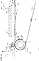
Fig. 1 is a configuration diagram illustrating a fixing device provided in an image forming device according to an embodiment of the present invention. -
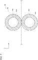
Fig. 2 is a cross-sectional view illustrating a main fixing portion of the fixing device provided in the image forming device according to the embodiment of the present invention. -
Fig. 3 is a table showing evaluation results of evaluating the image forming device according to the embodiment of the present invention and an image forming device according to a comparative embodiment. -
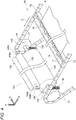
Fig. 4 is a perspective view illustrating the main fixing portion of the fixing device provided in the image forming device according to the embodiment of the present invention. -
Fig. 5 is a cross-sectional view illustrating the main fixing portion of the fixing device provided in the image forming device according to the embodiment of the present invention. -
Fig. 6 is a perspective view illustrating a conveying mechanism provided in the image forming device according to the embodiment of the present invention. -
Fig. 7 is a cross-sectional view illustrating a cooling unit provided in the image forming device according to the embodiment of the present invention. -
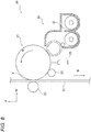
Fig. 8 is a configuration diagram illustrating a toner image forming unit provided in the image forming device according to the embodiment of the present invention. -
Fig. 9 is a configuration diagram illustrating the image forming device according to the embodiment of the present invention. -
Fig. 10 is a configuration diagram illustrating a fixing device provided in an image forming device according to a comparative embodiment of the present invention. - An example of an image forming device according to an embodiment of the present invention will be described with reference to
Figs. 1 to 10 . In the drawings, an arrow H indicates a device vertical direction (perpendicular direction), an arrow W indicates a device width direction (horizontal direction), and an arrow D indicates a device depth direction (horizontal direction). - An
image forming device 10 according to the embodiment is an electrophotographic image forming device that forms a toner image on a sheet member P. As illustrated inFig. 9 , theimage forming device 10 includes acontrol unit 160, anaccommodating portion 50, adischarge portion 52, animage forming unit 12, aconveying mechanism 60, areversing mechanism 80, afixing device 100, and acooling unit 90. - The
control unit 160 is configured with a central processing unit (CPU), a read only memory (ROM), a random access memory (RAM), and a hard disk drive (HDD) (none is shown). The CPU executes a processing program. The ROM stores various programs, various tables, parameters, and the like. The RAM is used as a work area or the like when the CPU executes various programs. - The
accommodating portion 50 has a function of accommodating the sheet member P as a recording medium. Theimage forming device 10 may include plural (for example, two) accommodatingportions 50, and may selectively send out the sheet member P from the plural accommodatingportions 50. - The
discharge portion 52 is a portion from which the sheet member P on which a toner image is formed is discharged. Specifically, after the toner image is fixed by thefixing device 100, the sheet member P cooled by thecooling unit 90 is discharged to thedischarge portion 52. - The
image forming unit 12 has a function of forming a toner image on the sheet member P by an electrophotographic method. Specifically, theimage forming unit 12 includes a tonerimage forming unit 20 that forms a toner image, and atransfer device 30 that transfers the toner image formed by the tonerimage forming unit 20 to the sheet member P. - Plural toner
image forming units 20 are provided so as to form a toner image for each color. Theimage forming device 10 includes tonerimage forming units 20 of a total of four colors of yellow (Y), magenta (M), cyan (C), and black (K). The (Y), (M), (C), and (K) shown inFig. 9 show constituent portions corresponding to the respective colors. - The toner
image forming units 20 of these colors have basically the same configuration except for toner to be used. Specifically, as illustrated inFig. 8 , the tonerimage forming unit 20 of each color includes a photosensitive drum 21 (photoconductor) that rotates in a direction indicated by an arrow A inFig. 8 , and acharger 22 that charges thephotosensitive drum 21. Further, the tonerimage forming unit 20 of each color includes anexposure device 23 that exposes thephotosensitive drum 21 charged by thecharger 22 to light to form an electrostatic latent image on thephotosensitive drum 21, and a developingdevice 24 that uses toner to develop the electrostatic latent image, which is formed on thephotosensitive drum 21 by theexposure device 23, so as to form a toner image. - The
transfer device 30 has a function of primarily transferring toner images of thephotosensitive drums 21 of the respective colors onto an intermediate transfer body in a superimposed manner, and secondarily transferring the superimposed toner images onto the sheet member P. Specifically, as illustrated inFig. 9 , thetransfer device 30 includes atransfer belt 31 as the intermediate transfer body, aprimary transfer roll 33, and atransfer unit 35. - The
primary transfer roll 33 has a function of transferring a toner image formed on thephotosensitive drum 21 to thetransfer belt 31 at a primary transfer position T (seeFig. 8 ) between thephotosensitive drum 21 and theprimary transfer roll 33. - The
transfer belt 31 has an endless shape, and is wound aroundplural rolls 32 to determine a posture thereof. When at least one of the plural rolls 32 is driven to rotate, thetransfer belt 31 rotates in a direction indicated by an arrow B, and conveys the primarily transferred toner image to a secondary transfer position NT to be described later. - The
transfer unit 35 has a function of transferring the toner image, which is transferred onto thetransfer belt 31, to the sheet member P. Specifically, thetransfer unit 35 includes asecondary transfer unit 34 and a facingroll 36. - The facing
roll 36 is disposed below thetransfer belt 31 so as to face thetransfer belt 31. Thesecondary transfer unit 34 is disposed on an inner side of thetransfer belt 31 such that thetransfer belt 31 is disposed between thesecondary transfer unit 34 and the facingroll 36. Specifically, thesecondary transfer unit 34 is configured with a corotron. In thetransfer unit 35, the toner image transferred onto thetransfer belt 31 is transferred onto the sheet member P passing through the secondary transfer position NT by a electrostatic force generated due to electricity-discharge of thesecondary transfer unit 34. Here, the secondary transfer position NT is a position where thetransfer belt 31 and the facingroll 36 are in contact with each other. - The conveying
mechanism 60 has a function of conveying the sheet member P accommodated in theaccommodating portion 50 to the secondary transfer position NT. Further, the conveyingmechanism 60 has a function of conveying the sheet member P from the secondary transfer position NT to themain heating unit 120 to be described later. The conveyingmechanism 60 will be described in detail later. - The reversing
mechanism 80 has a function of reversing the front and back of the sheet member P. The reversingmechanism 80 will be described in detail later. - The fixing
device 100 has a function of fixing the toner image, which is transferred onto the sheet member P by thetransfer device 30, onto the sheet member P. The fixingdevice 100 will be described in detail later. - The cooling
unit 90 has a function of cooling the sheet member P heated by the fixingdevice 100. As illustrated inFig. 9 , the coolingunit 90 is disposed downstream of themain heating unit 120 of the fixingdevice 100 in a conveyance direction of the sheet member P. The coolingunit 90 includes two cooling rolls 92 arranged in the device width direction. Since the two cooling rolls 92 have the same configuration, one of the cooling rolls 92 will be described. - As illustrated in
Fig. 7 , thecooling roll 92 includes a pair ofrolls roll 92a is disposed above the conveyance path of the sheet member P. Theroll 92b is disposed below the conveyance path of the sheet member P. - The
rolls cylindrical base members base members base members rolls - In this configuration, the
roll 92b is rotated by a rotational force transmitted from a driving member (not shown). Further, theroll 92a is driven to rotate by theroll 92b. Therolls - In the
image forming device 10 illustrated inFig. 9 , a toner image is formed as follows. - First, the charger 22 (see
Fig. 8 ) of each color, to which a voltage is applied, uniformly charges a surface of thephotosensitive drum 21 of each color at a predetermined negative potential. Subsequently, based on image data input from the outside, theexposure device 23 irradiates the charged surface of thephotosensitive drum 21 of each color with exposure light to form an electrostatic latent image. - Accordingly, electrostatic latent images corresponding to the image data are formed on respective surfaces of the photosensitive drums 21. Further, developing devices 40 of the respective colors develop the electrostatic latent images to form toner images on the respective surfaces of the
photosensitive drums 21 of the respective colors. Thetransfer device 30 transfers the toner images formed on the surfaces of thephotosensitive drums 21 of the respective colors onto thetransfer belt 31. - Meanwhile, the sheet member P is sent out from the
accommodating portion 50 illustrated inFig. 9 to the conveyance path of the sheet member P by the conveyingmechanism 60 to be described later. The sheet member P being conveyed along the conveyance path is sent out to the secondary transfer position NT where thetransfer belt 31 and the facingroll 36 are in contact with each other. At the secondary transfer position NT, the sheet member P is conveyed while being sandwiched between thetransfer belt 31 and the facingroll 36, and accordingly the toner images on a front surface of thetransfer belt 31 are transferred onto a first surface (= front surface) of the sheet member P. - Further, the fixing
device 100 fixes the toner images, which are transferred onto the first surface of the sheet member P, onto the sheet member P, and the sheet member P is conveyed to thecooling unit 90. The coolingunit 90 cools the sheet member P onto which the toner images are fixed, and discharges the sheet member P to thedischarge portion 52. - On the other hand, in a case of forming a toner image on a second surface (= back surface) of the sheet member P, the sheet member P that passes through the fixing
device 100 by being conveyed by the conveyingmechanism 60 is conveyed to the reversingmechanism 80. The sheet member P conveyed to the reversingmechanism 80 has the front and back thereof reversed by a reversingdevice 84. Conveying rolls 86 convey the sheet member P, whose front and back are reversed, to the conveyingmechanism 60. In order to form a toner image on the second surface of the sheet member P, conveyance of the sheet member P to the secondary transfer position NT, transfer of the toner image onto the second surface of the sheet member, and fixing of the toner image onto the second surface are performed in the same manner as described above. - Next, the conveying
mechanism 60, the reversingmechanism 80, and the fixingdevice 100 will be described. - As illustrated in
Fig. 9 , the conveyingmechanism 60 includes a sending-out roll 62, plural conveyingrolls 64, and achain gripper 66. The conveyingmechanism 60 is an example of a conveying unit. - The sending-
out roll 62 is a roll that sends out the sheet member P accommodated in theaccommodating portion 50. Theplural conveying rolls 64 include rolls that convey the sheet member P sent out by the sending-out roll 62 to thechain gripper 66, and rolls that convey the sheet member P conveyed by thechain gripper 66 to thecooling unit 90. Thechain gripper 66 has a function of conveying the sheet member P while holding a leading end portion of the sheet member P. Specifically, as illustrated inFig. 6 , thechain gripper 66 has a pair ofchains 72, andgrippers 76 serving as holding portions (= gripping portions). - The pair of
chains 72 is formed in an annular shape. Thechains 72 in a pair are disposed at an interval in the device depth direction. The pair ofchains 72 is wound around a pair of sprockets (not shown) disposed at both ends in an axial direction of the facing roll 36 (seeFig. 9 ), a pair of sprockets 71 (seeFig. 4 ) disposed at both ends in an axial direction of apressing roll 140 to be described later, and a pair of sprockets 74 (seeFig. 9 ). When one pair of the sprockets rotates, thechain 72 rotates in a direction indicated by an arrow C. -
Plural attachment members 75 extend between the pair ofchains 72 along the device depth direction, at predetermined intervals along a circumferential direction (rotational direction) of thechains 72. Thegrippers 76 are attached. -
Plural grippers 76 are attached to eachattachment member 75 at predetermined intervals along the device depth direction. Eachgripper 76 has a function of holding a leading end portion of the sheet member P. Specifically, eachgripper 76 has aclaw 76a. In addition, theattachment member 75 is formed with acontact portion 75a (seeFig. 5 ) with which theclaw 76a comes into contact. - When the leading end portion of the sheet member P is sandwiched between the
claw 76a of thegripper 76 and thecontact portion 75a of theattachment member 75, the sheet member P gets held. For example, theclaw 76a of thegripper 76 is pressed against thecontact portion 75a of theattachment member 75 by a spring or the like, and theclaw 76a is brought into contact with or separated from thecontact portion 75a by an action of a cam or the like. - In the
chain gripper 66, thechain 72 rotates in the direction indicated by the arrow C in a state where the leading end portion of the sheet member P is held between thegripper 76 and theattachment member 75, thereby conveying the sheet member P. Thechain gripper 66 conveys the sheet member P conveyed by theplural conveying rolls 64 to the secondary transfer position NT, and further conveys the sheet member P to themain heating unit 120 described later after passing the sheet member P through a preheatingunit 102 described later. A part of the conveyance path in the conveyingmechanism 60 along which the sheet member P is conveyed is indicated by a one-dot chain line inFig. 9 . - In this configuration, at least from the secondary transfer position NT to the
main heating unit 120, the conveyingmechanism 60 conveys the sheet member P with both sheet surfaces (= recording surfaces) thereof facing in the vertical direction. In other words, at least from the secondary transfer position NT to themain heating unit 120, the conveyingmechanism 60 conveys the sheet member P with a surface having an unfixed toner image being directed upward. - Further, there is case where toner images are formed on the first surface (= front surface) and the second surface (= back surface) of the sheet member P. Hereinafter, this is referred to as "the case of double-sided printing". In this case, when the sheet member P having an image transferred onto the second surface thereof is heated by the preheating
unit 102 to be described later, the conveyingmechanism 60 conveys the sheet member P with an image forming region of the first surface of the sheet member P in a state of not being in contact with other members. In other words, arrangement of other members is determined in consideration of a conveyance posture of the sheet member P being conveyed by the conveyingmechanism 60. The "image forming region" refers to a portion other than an outer peripheral portion of the sheet member P where an image cannot be formed, and is a region where an image is formed when a solid image is formed on the sheet member P. - As illustrated in
Fig. 9 , the reversingmechanism 80 includes plural conveyingrolls 82, the reversingdevice 84, and plural conveying rolls 86. The reversingmechanism 80 is an example of a reversing unit. - The
plural conveying rolls 82 convey the sheet member P sent from the fixingdevice 100 to the reversingdevice 84. The reversingdevice 84 is, for example, a device that conveys the sheet member P while rotating the sheet member P plural times such that the conveyance direction of the sheet member P changes by, for example, 90 degrees each time, thereby twisting the sheet member P like a mevius band to reverse the front and back of the sheet member P. Theplural conveying rolls 86 are rolls that convey the sheet member P whose front and back are reversed by the reversingdevice 84 to thechain gripper 66. - In this configuration, in the case of double-sided printing, the reversing
mechanism 80 reverses the front and back of the sheet member P having the toner image fixed onto the first surface thereof. Then, the reversingmechanism 80 sends the sheet member P again to the secondary transfer position NT through the conveyingmechanism 60. - As illustrated in
Fig. 1 , the fixingdevice 100 includes the preheatingunit 102 that heats the sheet member P being conveyed in a state of not being in contact with the sheet member P, themain heating unit 120 that comes into contact with the sheet member P to heat and press the sheet member P, and ablowing unit 170. - As illustrated in
Fig. 1 , the preheatingunit 102 is disposed downstream of the secondary transfer position NT (seeFig. 9 ) in the conveyance direction of the sheet member P and above the conveyance path of the sheet member P. In other words, the preheatingunit 102 is disposed on a side of the unfixed toner image transferred onto the sheet member P. That is, the preheatingunit 102 is provided on the same side as thetransfer unit 35 with respect to the conveyance path of the sheet member P. The preheatingunit 102 includes a reflectingplate 104, plural infrared heaters 106 (hereinafter referred to as "heaters 106"), and awire mesh 112. - The reflecting
plate 104 is formed of an aluminum plate, and has a shallow bottomed box shape opened on a side of the sheet member P being conveyed. In the present embodiment, as viewed from above, the reflectingplate 104 covers, in the device depth direction, the sheet member P being conveyed. - The
heater 106 has a cylindrical shape extending in the device depth direction, and plural theheaters 106 are accommodated inside the box-shaped the reflectingplate 104. In the present embodiment, as viewed from above, theheaters 106 cover, in the device depth direction, the sheet member P being conveyed. Eachheater 106 is separated from the conveyance path of the sheet member P by 30 mm in an upward direction. - The
plural heaters 106 are arranged at intervals in the device width direction. In the present embodiment, as viewed from above, a region where theplural heaters 106 are arranged covers, in the device width direction, one sheet member P being conveyed. In other words, theplural heaters 106 heat at one time the entire sheet member P being conveyed. - In the above configuration, from the
heater 106, an infrared ray having a maximum spectral radiance at a wavelength of 3 µm or more and 5 µm or less is emitted. A surface temperature of theheater 106 is a predetermined temperature of 300°C or higher and 1175°C or lower. - The
wire mesh 112 is fixed to an edge portion of an opening of the box-shaped reflectingplate 104 by a fixing member (not shown), and partitions the inside of the box-shaped reflectingplate 104 from the outside of the reflecting plate 110. Accordingly, thewire mesh 112 prevents the sheet member P being conveyed from coming into contact with theheater 106 inside the box-shaped reflectingplate 104. - In this configuration, the preheating
unit 102 heats the sheet member P in a non-contact state from the unfixed toner image side. In other words, the preheatingunit 102 functions as a softening unit that softens an unfixed toner. - Further, in a case of single-sided printing, when heating the sheet member P having the toner image transferred onto the first surface thereof, the preheating
unit 102 heats the sheet member P so that a temperature of the first surface of the sheet member P is equal to or higher than a softening point of the toner or close to the softening point before the sheet member P is heated by themain heating unit 120. - In the case of double-sided printing, when heating the sheet member P having the toner image transferred onto the second surface thereof, the preheating
unit 102 heats the sheet member P so that the temperature of the first surface of the sheet member P is lower than the softening point of the toner before the sheet member P is heated by themain heating unit 120. - Here, the "temperature of the first surface of the sheet member P before the sheet member P being heated by the
main heating unit 120" is, as will be described later, the temperature of the first surface of the sheet member P at a position S01 separated from an upstream end of a nip portion N of themain heating unit 120 in the conveyance direction toward an upstream side in the conveyance direction by 100 mm. That is, when facing the second surface to heat the toner image transferred onto the second surface, the preheatingunit 102 heats the sheet member P such that the temperature of the first surface at the position S01 is lower than the softening point of the toner. In other words, an output of the preheatingunit 102 is adjusted such that the temperature of the first surface at the position S01 is lower than the softening point of the toner. Specifically, even when the toner image transferred onto the second surface is a black solid image, the output of the preheatingunit 102 is adjusted such that the temperature of the first surface at the position S01 is lower than the softening point of the toner. - In the present embodiment, as an example, an output condition of the preheating
unit 102 under which the temperature of the first surface of the sheet member P is lower than the softening point of the toner is obtained in advance for each paper type or size by a test, and an output table of the preheatingunit 102 is stored in thecontrol unit 160. Then, thecontrol unit 160 adjusts the output of the preheatingunit 102 based on information of the paper type or size input by a user. Accordingly, the preheatingunit 102 heats the sheet member P such that the temperature of the first surface of the sheet member P is lower than the softening point of the toner. The temperature of the first surface at the position S01 may be measured by a temperature sensor, and thecontrol unit 160 may adjust the output of the preheatingunit 102 based on a measurement result, thereby heating the sheet member P such that the temperature of the first surface of the sheet member P is lower than the softening point of the toner. - Here, "the softening point of the toner (= glass transition temperature of the toner)" is a 1/2 descent rate measured under conditions of a die pore diameter of 0.5 mm, a pressure load of 0.98 MPa, and a temperature increase rate of 1 °C/min in a temperature increase test using a flow tester (CFT500, manufactured by Shimadzu Corporation). Note that the 1/2 descent rate is a temperature corresponding to 1/2 of a height obtained from an outflow start point to an end point when a toner sample is melted and flowed out.
- As illustrated in
Fig. 1 , theblowing unit 170 is disposed so as to face the preheatingunit 102 in the vertical direction, and the sheet member P being conveyed passes between the blowingunit 170 and the preheatingunit 102. Theblowing unit 170 includesplural fans 172 arranged in the device width direction and the device depth direction. Thefan 172 is an example of a blowing unit. - In this configuration, when the
plural fans 172 blow air toward the sheet member P passing between the blowingunit 170 and the preheatingunit 102, the conveyance posture of the sheet member P conveyed with the leading end portion thereof being held is stabilized. Thefan 172 is an example of a stabilizing unit. - Here, "the conveyance posture of the sheet member P is stabilized" means that a distance from a rear end portion of the sheet member in a state of being bent by gravity to the
preheating unit 102 is smaller than when the stabilizing unit is not provided. It is preferable that a distance from the sheet surface of the sheet member P to thepreheating unit 102 is longer than a distance from the preheatingunit 102 to thegripper 76, and that variation in the distance to thepreheating unit 102 depending on a position of the sheet surface is suppressed. In other words, the distance from the sheet surface of the sheet member P to thepreheating unit 102 is preferably longer than the distance from the preheatingunit 102 to thegripper 76, and a difference between a longest distance from the sheet surface of the sheet member P to thepreheating unit 102 and a shortest distance is preferably reduced. Here, an output of thefan 172 may be adjusted. In the present embodiment, as an example, an output condition of thefan 172 is obtained for each paper type or size, and an output table of thefan 172 is stored in thecontrol unit 160. Then, thecontrol unit 160 adjusts the output of thefan 172 based on the information of the paper type or size input by the user. For example, when a paper thickness input by the user is larger than a predetermined value or a size is larger than a predetermined value, the output of the fan is increased. The distance from the sheet surface of the sheet member P to thepreheating unit 102 may be measured by an optical sensor, and thecontrol unit 160 may adjust the output of thefan 172 based on a measurement result thereof. - Further, when the
plural fans 172 blow air toward the sheet member P, the temperature of the sheet surface of the sheet member P on a side to which the air is blown decreases. In this way, thefan 172 functions as a temperature reducing unit. - As illustrated in
Fig. 1 , themain heating unit 120 is disposed downstream of the preheatingunit 102 in the conveyance direction of the sheet member P. Themain heating unit 120 includes aheating roll 130 that comes into contact with the sheet member P being conveyed to heat the sheet member P, apressing roll 140 that presses the sheet member P toward theheating roll 130, and a drivenroll 150 that is driven to rotate by therotating heating roll 130. - As illustrated in
Fig. 1 , theheating roll 130 is disposed so as to come into contact with a surface facing upward of the sheet member P being conveyed and extend in the device depth direction with an axial direction thereof serving as the device depth direction. Theheating roll 130 includes acylindrical base member 132, arubber layer 134 formed so as to cover an entire circumference of thebase member 132, arelease layer 136 formed so as to cover an entire circumference of therubber layer 134, and aheater 138 accommodated in thebase member 132. An outer diameter of an outer circumferential surface of therelease layer 136 of theheating roll 130 is, for example, 80 mm. - The
base member 132 is an aluminum tube and has a thickness of 20 mm, for example. Therubber layer 134 is made of silicone rubber, and has a thickness of 6 mm, for example. Further, therelease layer 136 is made of a copolymer of tetrafluoroethylene and perfluoroethylene (PFA resin), and has a thickness of 50 µm, for example. - As illustrated in
Fig. 4 ,shaft portions 139a extending in the device depth direction are formed at both end portions of theheating roll 130 respectively in the device depth direction. Eachshaft portion 139a is supported by asupport member 139b. Theheating roll 130 is rotatably supported bysupport members 139b at both end portions of theheating roll 130. - As illustrated in
Figs. 1 and4 , the drivenroll 150 is disposed so as to extend in the device depth direction with an axial direction thereof serving as the device depth direction, on an opposite side of theheating roll 130 than the sheet member P being conveyed. The drivenroll 150 includes acylindrical base member 152 and aheater 154 accommodated in thebase member 152. An outer diameter of an outer circumferential surface of thebase member 152 of the drivenroll 150 is, for example, 50 mm. - The
base member 152 is an aluminum tube and has a thickness of 10 mm, for example. The drivenroll 150 is rotatably supported by a support member (not shown) at both end portions of the drivenroll 150. - In this configuration, the driven
roll 150 is driven to rotate by theheating roll 130. The drivenroll 150 heats theheating roll 130. As described above, since theheating roll 130 is heated by the drivenroll 150 and theheating roll 130 itself has theheater 138, a surface temperature of theheating roll 130 becomes a predetermined temperature of 180°C or higher and 200°C or lower. - As illustrated in
Figs. 1 and4 , thepressing roll 140 is provided on an opposite side of the sheet member P being conveyed than theheating roll 130, and is disposed so as to be in contact with a surface facing downward of the sheet member P being conveyed and extend in the device depth direction with an axial direction thereof serving as the device depth direction. Thepressing roll 140 includes acylindrical base member 142, arubber layer 144 formed so as to cover thebase member 142, arelease layer 146 formed so as to cover therubber layer 144, and a pair of shaft portions 148 (seeFig. 4 ) formed at both end portions in the device depth direction. An outer diameter of an outer circumferential surface of therelease layer 146 of thepressing roll 140 is, for example, 225 mm. Thus, an outer diameter of thepressing roll 140 is larger than an outer diameter of the heating roll. - The
base member 142 is an aluminum tube and has a thickness of 20 mm, for example. Therubber layer 144 is made of silicone rubber and has a thickness of 1 mm, for example. Further, therelease layer 146 is made of a copolymer of tetrafluoroethylene and perfluoroethylene (PFA resin), and has a thickness of 50 µm, for example. - A recessed
portion 140a extending in the device depth direction is formed in an outer circumferential surface of thepressing roll 140. As illustrated inFig. 5 , when the sheet member P passes between thepressing roll 140 and theheating roll 130, thegripper 76 that grips the leading end portion of the sheet member P is accommodated in the recessedportion 140a. - As illustrated in
Fig. 4 , the pair ofshaft portions 148 are formed at both end portions of thepressing roll 140 in the device depth direction, have a diameter smaller than that of the outer circumferential surface of therelease layer 146 of thepressing roll 140, and extend in the axial direction. - In this configuration, the
pressing roll 140 is rotated by a rotational force transmitted from a driving member (not shown). Further, theheating roll 130 is driven to rotate by the rotatingpressing roll 140, and the drivenroll 150 is driven to rotate by therotating heating roll 130. When conveying the sheet member P while sandwiching the sheet member P onto which the toner image is transferred, theheating roll 130 and thepressing roll 140 fix the toner image onto the sheet member P. - As illustrated in
Fig. 4 , themain heating unit 120 includes asupport member 156 that supports thepressing roll 140, and a biasingmember 158 that biases thepressing roll 140 toward theheating roll 130 side via thesupport member 156. - A pair of
support members 156 is disposed so as to rotatably support the pair ofshaft portions 148 of thepressing roll 140 from below. - Biasing
members 158 in a pair are compression springs, and are disposed on an opposite side of thesupport members 156 than theshaft portions 148. - In this configuration, the pair of biasing
members 158 bias thepressing roll 140 toward theheating roll 130 side, so that thepressing roll 140 presses the sheet member P toward theheating roll 130. Then, as illustrated inFig. 2 , a portion of theheating roll 130 that is biased by thepressing roll 140 is deformed, and the nip portion N that is a region where theheating roll 130 and thepressing roll 140 are in contact with each other is formed. - Next, an operation of the
image forming device 10 will be described in comparison with animage forming device 510 according to a comparative embodiment. First, with respect to a configuration of theimage forming device 510 according to the comparative embodiment, portions different from those of theimage forming device 10 will be described mainly. Note that with respect to an operation of theimage forming device 510, portions different from those of theimage forming device 10 will also be described mainly. - The
image forming device 510 includes theaccommodating portion 50, thedischarge portion 52, theimage forming unit 12, the conveyingmechanism 60, the reversingmechanism 80, a fixingdevice 600, and thecooling unit 90. As illustrated inFig. 10 , the fixingdevice 600 includes apreheating unit 602 that heats the sheet member P being conveyed in a state of not being in contact with the sheet member P, and themain heating unit 120. - In this configuration, the preheating
unit 602 heats the sheet member P in a non-contact state from an unfixed toner image side. In the case of double-sided printing, before themain heating unit 120 heats the sheet member P, the temperature of the first surface of the sheet member P is equal to or higher than the softening point of the toner since the preheatingunit 602 heats the sheet member P having a toner image transferred onto the second surface thereof. - In the
image forming device 10 illustrated inFig. 9 , the conveyingmechanism 60 conveys the sheet member P to the secondary transfer position NT, and at the secondary transfer position NT, thetransfer belt 31 and the facingroll 36 convey the sheet member P while sandwiching the sheet member P. Accordingly, a toner image on a front surface of thetransfer belt 31 is transferred onto the first surface (= front surface) of the sheet member P. - Thereafter, while the conveying
mechanism 60 conveys the sheet member P with both sheet surfaces thereof facing in the vertical direction, the preheatingunits Figs. 1 and10 heat the sheet member P in a non-contact state from the first surface side (= unfixed toner image side) of the sheet member P being conveyed by the conveyingmechanism 60. When the preheatingunit 102 illustrated inFig. 1 heats the sheet member P, thefan 172 blows air toward the second surface (= back surface) of the sheet member P. Accordingly, the conveyance posture of the sheet member P in a state of being heated by the preheatingunit 102 is stabilized. - Further, the
main heating units 120 illustrated inFigs. 1 and10 fix the toner image onto the first surface of the sheet member P when the sheet member P is conveyed in a sandwiched manner by theheating roll 130 and thepressing roll 140. In addition, the reversingmechanism 80 receives the sheet member P having the toner image fixed onto the first surface thereof from themain heating unit 120, conveys the sheet member P, and reverses the front and back of the sheet member P. Further, the conveyingmechanism 60 receives the sheet member P whose front and back are reversed from the reversingmechanism 80 and conveys the sheet member P. - The conveying
mechanism 60 conveys the sheet member P again to the secondary transfer position NT, and at the secondary transfer position NT, thetransfer belt 31 and the facingroll 36 convey the sheet member P while sandwiching the sheet member P. Accordingly, a toner image on the front surface of thetransfer belt 31 is transferred onto the second surface (= back surface) of the sheet member P. - Thereafter, while the conveying
mechanism 60 conveys the sheet member P with both sheet surfaces thereof facing in the vertical direction, the preheatingunits mechanism 60. When the preheatingunit 102 illustrated inFig. 1 heats the sheet member P, thefan 172 of theblowing unit 170 blows air toward the first surface (= front surface) of the sheet member P. Accordingly, a posture of the sheet member P in a state of being heated by the preheatingunits - When the preheating
units mechanism 60 conveys the sheet member P with an image forming region on the first surface of the sheet member P in a state of not being in contact with other members. - Further, the
main heating unit 120 fixes the toner image onto the second surface of the sheet member P when the sheet member P is conveyed in a sandwiched manner by theheating roll 130 and thepressing roll 140. In this way, the toner image on the first surface is sandwiched twice by theheating roll 130 and thepressing roll 140. In addition, the coolingunit 90 cools the sheet member P having the toner images fixed onto both surfaces thereof, and discharges the sheet member P to thedischarge portion 52. - Here, before the
main heating unit 120 heats the sheet member P, the temperature of the first surface of the sheet member P becomes equal to or higher than the softening point of the toner since the sheet member P having the toner image transferred onto the second surface thereof is heated by the preheatingunit 602 illustrated inFig. 10 . In other words, since the preheatingunit 602 heats the sheet member P having the toner image transferred onto the second surface thereof, the temperature of the first surface at the position S01 illustrated inFig. 2 becomes equal to or higher than the softening point of the toner. As described above, when the temperature of the first surface at the position S01 is equal to or higher than the softening point of the toner, the sheet member P is heated by themain heating unit 120 in a state where the temperature of the first surface is equal to or higher than the softening point of the toner. - In contrast, when heating the sheet member P having the toner image transferred onto the second surface thereof, the preheating
unit 102 illustrated inFig. 1 heats the sheet member P so that the temperature of the first surface of the sheet member P is lower than the softening point of the toner before the sheet member P is heated by themain heating unit 120. In other words, when heating the toner image transferred onto the second surface, the preheatingunit 102 heats the sheet member P such that the temperature of the first surface at the position S01 illustrated inFig. 2 is lower than the softening point of the toner. As described above, since the temperature of the first surface at the position S01 is lower than the softening point of the toner, the sheet member P is heated by themain heating unit 120 in a state where the temperature of the first surface is lower than the softening point of the toner. - Next, since the glossiness (= gloss) of the toner images output by the
image forming devices -
- (a) In Example 1, the preheating
unit 102 heated, from a second surface side, the sheet member P having a toner image transferred onto a second surface thereof such that a temperature of a first surface thereof at the position S01 was 60°C and a temperature of the second surface was 65°C. - (b) In Example 2, the preheating
unit 102 heated, from a second surface side, the sheet member P having a toner image transferred onto a second surface thereof such that a temperature of a first surface thereof at the position S01 was 65°C and a temperature of the second surface was 70°C. - (c) In Example 3, the preheating
unit 102 heated, from a second surface side, the sheet member P having a toner image transferred onto a second surface thereof such that a temperature of a first surface thereof at the position S01 was 70°C and a temperature of the second surface was 75°C. - (d) In Comparative Example 1, the preheating
unit 602 heated, from a second surface side, the sheet member P having a toner image transferred onto a second surface thereof such that a temperature of a first surface thereof at the position S01 was 80°C and a temperature of the second surface thereof was 85°C. - (e) In Comparative Example 2, the preheating
unit 602 heated, from a second surface side, the sheet member P having a toner image transferred onto a second surface thereof such that a temperature of a first surface thereof at the position S01 was 90°C and a temperature of the second surface thereof was 95°C. - (f) In Comparative Example 3, the sheet member P having a toner image transferred onto a second surface thereof was heated by the preheating unit such that a temperature of a first surface thereof at the position S01 was 75°C and a temperature of the second surface thereof was 70°C. In Comparative Example 3, differently from Examples 1 to 3 and Comparative Examples 1 and 2, the preheating unit heated, from a first surface side, the sheet member P having the toner image transferred onto the second surface thereof. That is, the preheating unit is disposed below the sheet member P being conveyed.
- The details other than those described above were all similar to each other.
- As the sheet member P, an OS coated paper of A4 size (manufactured by Fuji Xerox Co., Ltd., basis weight: 127.9 g/m2) was used. Then, a black solid image (an image of 100% black area coverage) was formed on both surfaces of the sheet member P.
- The surface temperature of the
heating roll 130 was set to 200°C, and pressure at the nip portion N where theheating roll 130 and thepressing roll 140 were in contact with each other was set to 250 KPa. - The difference (= gloss difference) between the glossiness of the first surface and the glossiness of the second surface of the sheet member P, which was output, was evaluated. The glossiness was evaluated using a gloss meter (AG-4430 manufactured by BYK-Gardner). Specifically, this gloss meter was used to perform measurement at an incident angle of 60 degrees in a specular gloss measurement method (JIS Z 8741), and a measured value was defined as the glossiness.
- When a difference between glossiness of a toner image on a first surface and glossiness of a toner image on a second surface is large even though the toner images are formed by the same image forming device, a user feels uncomfortable. In this evaluation, when the difference between the glossiness of the toner image on the first surface and the glossiness of the toner image on the second surface is 10 or less, it is considered that the user does not feel uncomfortable, and the evaluation is "good"; when the difference between the glossiness of the toner image on the first surface and the glossiness of the toner image on the second surface is larger than 10, the evaluation is "poor".
- The evaluation results are shown in a table of
Fig. 3 . As shown in the table ofFig. 3 , in Examples 1 to 3 in which the temperature of the first surface was lower than the softening point of the toner, the evaluation result was "good". In contrast, in Comparative Examples 1 to 3 in which the temperature of the first surface was equal to or higher than the softening point of the toner, the evaluation result was "poor". - In the case of double-sided printing, the toner image on the first surface is sandwiched twice by the
heating roll 130 and thepressing roll 140, and the toner image on the second surface is sandwiched once by theheating roll 130 and thepressing roll 140. - Here, in Comparative Examples 1 to 3, the temperature of the first surface at the position S01 is equal to or higher than the softening point of the toner. Therefore, when the toner image formed on the first surface is sandwiched by the
heating roll 130 and thepressing roll 140 for the second time, surface roughness of a surface of the toner image is reduced than that in a case where the toner image is sandwiched only once, and the glossiness is improved. - On the other hand, in Examples 1 to 3, the temperature of the first surface at the position S01 is lower than the softening point of the toner. Therefore, when the toner image formed on the first surface is sandwiched by the
heating roll 130 and thepressing roll 140 for the second time, the occurrence that the surface roughness of the surface of the toner image is reduced and the glossiness is improved is suppressed. - Therefore, as shown in the table of
Fig. 3 , in Comparative Examples 1 to 3, the difference between the glossiness of the first surface and the glossiness of the second surface was large, and the evaluation result was considered to be "poor". On the other hand, in Examples 1 to 3, the difference between the glossiness of the first surface and the glossiness of the second surface was small and the evaluation result was considered to be "good". - As described above, when heating the sheet member P having the toner image transferred onto the second surface thereof, the preheating
unit 102 heats the sheet member P so that the temperature of the first surface of the sheet member P is lower than the softening point of the toner before the sheet member P is heated by themain heating unit 120. Therefore, as seen from the evaluation results described above, the difference between the glossiness of the toner image on the first surface and the glossiness of the toner image on the second surface is smaller than that in the case of using theimage forming device 510 according to the comparative embodiment. - The preheating
unit 102 heats the sheet member P in a non-contact state from the unfixed toner image side. That is, when heating the sheet member P having the toner image transferred onto the second surface thereof, the preheatingunit 102 heats the sheet member P from the second surface side. Therefore, the temperature of the second surface of the sheet member P onto which the unfixed toner image is transferred is higher than the temperature of the first surface of the sheet member P onto which the toner image is fixed. - In addition, since the temperature of the second surface of the sheet member P onto which the unfixed toner image is transferred is higher than the temperature of the first surface, the glossiness of the toner image on the second surface is improved as compared with a case where the temperature of the second surface is lower than the temperature of the first surface.
- When the sheet member P is to be heated by the preheating
unit 102, the conveyingmechanism 60 conveys the sheet member P with the sheet surface thereof facing in the vertical direction. Further, the preheatingunit 102 heats the sheet member P from above the sheet member, and thefan 172 blows air to the sheet member P from below the sheet member P. As described above, when the sheet member P having the toner image transferred onto the second surface thereof is heated by the preheatingunit 102, thefan 172 blows air to the sheet member P from the first surface side of the sheet member P. Therefore, the temperature of the first surface is easily lower than the softening point of the toner, as compared with a case where air on the first surface side is stagnant. - When the sheet member P is to be heated by the preheating
unit 102, the conveyingmechanism 60 conveys the sheet member P with the sheet surface thereof facing in the vertical direction. Further, the preheatingunit 102 heats the sheet member P from above the sheet member, and thefan 172 blows air to the sheet member P from below the sheet member P. Therefore, the conveyance posture of the sheet member P being conveyed is stabilized as compared with a case where the sheet member P is conveyed in a state of being bent by gravity. - In addition, since the conveyance posture of the sheet member P is stabilized, a temperature of the rear end portion of the sheet member P is prevented from being lower than a temperature of the leading end portion of the sheet member P as compared with a case where the sheet member P is conveyed in a state of being bent by gravity.
- When the preheating
unit 102 heats the sheet member P having the image transferred onto the second surface thereof, the conveyingmechanism 60 conveys the sheet member P with the image forming region on the first surface of the sheet member P in a state of not being in contact with other members. Therefore, as compared with a case where the image forming region on the first surface of the sheet member P is in contact with another member, occurrence of a difference in temperature in one sheet member P is suppressed, and thus a difference in glossiness of the toner image formed on the first surface of the sheet member P occurs. - When the sheet member P is to be heated by the preheating
unit 102, the conveyingmechanism 60 conveys the sheet member P with the sheet surface thereof facing in the vertical direction. In addition, the preheatingunit 102 heats the sheet member P from above the sheet member. Therefore, as compared with a case where the conveying mechanism conveys the sheet member P with the sheet surface thereof being directed in a horizontal direction and the preheating unit heats the sheet member P from the horizontal direction, hot air generated by the preheating unit is suppressed from rising and escaping from between the sheet member P and the preheating unit. - Although the present invention is described in detail with reference to specific embodiments, it is apparent to those skilled in the art that the present invention is not limited to the embodiments, and various other embodiments can be taken within the scope of the present invention. For example, in the above-described embodiment, the preheating
unit 102 heats the sheet member P from the unfixed toner image side in a non-contact state, and alternatively, the preheating unit may heat the sheet member P in a state of being in contact with the sheet member P. However, in this case, an effect obtained when the preheatingunit 102 heats the sheet member P in a non-contact state is not obtained. - Although not particularly described in the above-described embodiment, a temperature detection member may be provided at the position S01, and the output of the preheating
unit 102 may be adjusted based on a detection result thereof. - Although not particularly described in the above-described embodiment, a cooling member may be provided that cools the first surface of the sheet member P before the toner image is fixed onto the second surface by the
main heating unit 120. - In the above-described embodiment, when the preheating
unit 102 heats the sheet member P having the image transferred onto the second surface thereof, the conveyingmechanism 60 conveys the sheet member P with the image forming region on the first surface of the sheet member P in a state of not being in contact with other members, and alternatively, the image forming region on the first surface may contact with other members. However, in this case, an effect produced by the non-contact state is not produced. - When the temperature of the first surface at the position S01 is lower than the softening point of the toner, the preheating
unit 102 may cause the temperature of the second surface to be lower than the softening point of the toner, or to be equal to or higher than the softening point of the toner. However, in order to easily fix the toner onto the sheet member P with themain heating unit 120, it is preferable that the temperature of the second surface is equal to or higher than the softening point of the toner. - This application claims the priority of
Japanese Patent Application No. 2019-028810 filed on February 20, 2019
Claims (8)
- An image forming device comprising:a transfer unit that transfers a toner image onto a recording medium being conveyed;a main heating unit that is arranged downstream of the transfer unit in a conveyance direction of the recording medium, comes into contact with the recording medium to heat the recording medium, and fixes the toner image onto the recording medium;a reversing unit that reverses front and back of the recording medium having a first toner image fixed onto a first surface of the recording medium by the main heating unit, and sends the recording medium to the transfer unit; anda preheating unit that is arranged between the transfer unit and the main heating unit in the conveyance direction of the recording medium and heats the recording medium having a second toner image transferred onto a second surface of the recording medium, whereinthe preheating unit heats the recording medium so that a temperature of the first surface of the recording medium is lower than a softening point of a toner before the recording medium is heated by the main heating unit.
- The image forming device according to claim 2, wherein
the preheating unit heats the recording medium from a side of an unfixed toner image in a non-contact state. - The image forming device according to claim 2, whereinthe recording medium is conveyed with a recording surface facing in a vertical direction when the preheating unit heats the recording medium having an image transferred onto the second surface,the preheating unit heats a recording member from above the recording member, anda blowing unit that blows air to the recording medium is provided on an opposite side of the recording medium being conveyed than the preheating unit.
- The image forming device according to claim 1, further comprisinga conveying unit that grips a leading end portion of the recording medium and conveys the recording medium, wherein,when the preheating unit heats the recording medium having an image transferred onto the second surface, the conveying unit conveys the recording medium with an image forming region on the first surface of the recording medium being in a non-contact state with another member.
- The image forming device according to claim 2, further comprisinga conveying unit that grips a leading end portion of the recording medium and conveys the recording medium, wherein,when the preheating unit heats the recording medium having an image transferred onto the second surface, the conveying unit conveys the recording medium with an image forming region on the first surface of the recording medium being in a non-contact state with another member.
- The image forming device according to claim 3, further comprisinga conveying unit that grips a leading end portion of the recording medium and conveys the recording medium, wherein,when the preheating unit heats the recording medium having an image transferred onto the second surface, the conveying unit conveys the recording medium with an image forming region on the first surface of the recording medium being in a non-contact state with another member.
- The image forming device according to claim 4, whereinthe conveying unit conveys the recording medium with a recording surface facing in a vertical direction when the preheating unit heats the recording medium having an image transferred onto the second surface,the preheating unit heats a recording member from above the recording member, anda stabilizing unit that stabilizes a conveyance posture of the recording member is arranged on a side opposite to the preheating unit on an opposite side of the recording medium being conveyed than the preheating unit in a non-contact state with the recording medium.
- The image forming device according to claim 5, whereinthe conveying unit conveys the recording medium with a recording surface facing in a vertical direction when the preheating unit heats the recording medium having an image transferred onto the second surface,the preheating unit heats a recording member from above the recording member, anda stabilizing unit that stabilizes a conveyance posture of the recording member is arranged on a side opposite to the preheating unit on an opposite side of the recording medium being conveyed than the preheating unit in a non-contact state with the recording medium.
Applications Claiming Priority (2)
| Application Number | Priority Date | Filing Date | Title |
|---|---|---|---|
| JP2019028810 | 2019-02-20 | ||
| PCT/JP2019/030789 WO2020170471A1 (en) | 2019-02-20 | 2019-08-05 | Image forming device |
Publications (3)
| Publication Number | Publication Date |
|---|---|
| EP3929663A1 true EP3929663A1 (en) | 2021-12-29 |
| EP3929663A4 EP3929663A4 (en) | 2022-11-23 |
| EP3929663B1 EP3929663B1 (en) | 2025-07-02 |
Family
ID=72143923
Family Applications (1)
| Application Number | Title | Priority Date | Filing Date |
|---|---|---|---|
| EP19916127.4A Active EP3929663B1 (en) | 2019-02-20 | 2019-08-05 | Image forming device |
Country Status (5)
| Country | Link |
|---|---|
| US (1) | US11385582B2 (en) |
| EP (1) | EP3929663B1 (en) |
| JP (1) | JP7404853B2 (en) |
| CN (1) | CN113316745B (en) |
| WO (1) | WO2020170471A1 (en) |
Cited By (1)
| Publication number | Priority date | Publication date | Assignee | Title |
|---|---|---|---|---|
| EP3932840A4 (en) * | 2019-02-28 | 2022-12-28 | Fujifilm Business Innovation Corp. | IMAGE FORMING DEVICE |
Families Citing this family (3)
| Publication number | Priority date | Publication date | Assignee | Title |
|---|---|---|---|---|
| JP7139979B2 (en) * | 2019-01-31 | 2022-09-21 | 富士フイルムビジネスイノベーション株式会社 | Fixing device, image forming device |
| JP7268416B2 (en) * | 2019-03-14 | 2023-05-08 | 富士フイルムビジネスイノベーション株式会社 | CONVEYING DEVICE, FIXING DEVICE, AND IMAGE FORMING APPARATUS |
| JP7563095B2 (en) * | 2020-10-12 | 2024-10-08 | 富士フイルムビジネスイノベーション株式会社 | Transfer device and image forming device |
Family Cites Families (24)
| Publication number | Priority date | Publication date | Assignee | Title |
|---|---|---|---|---|
| DE59300291D1 (en) | 1993-07-28 | 1995-07-27 | Siemens Nixdorf Inf Syst | Heat-fixing device for recording media of a printing or copying machine printed on one or both sides. |
| JP3322008B2 (en) | 1994-08-05 | 2002-09-09 | 日立工機株式会社 | Continuous paper duplex printing system |
| JP4292698B2 (en) * | 1996-08-23 | 2009-07-08 | 富士ゼロックス株式会社 | Image forming method |
| JP2000047503A (en) * | 1998-07-28 | 2000-02-18 | Canon Inc | Image forming device |
| JP2007511795A (en) * | 2003-11-15 | 2007-05-10 | イーストマン コダック カンパニー | Toner image fixation in duplex printing |
| JP2007017495A (en) * | 2005-07-05 | 2007-01-25 | Konica Minolta Business Technologies Inc | Image forming apparatus |
| CN100495243C (en) * | 2005-08-30 | 2009-06-03 | 株式会社理光 | Image forming apparatus and image forming method |
| KR100856413B1 (en) * | 2006-12-06 | 2008-09-04 | 삼성전자주식회사 | Fuser and an image forming apparatus including the same |
| JP4858196B2 (en) * | 2007-01-31 | 2012-01-18 | 富士ゼロックス株式会社 | Fixing device |
| KR100873442B1 (en) * | 2007-06-25 | 2008-12-11 | 삼성전자주식회사 | A fixing apparatus, an image forming apparatus having the same, and a fixing method of the image forming apparatus |
| JP2009163065A (en) * | 2008-01-08 | 2009-07-23 | Mitsubishi Heavy Ind Ltd | Liquid toner fixing device, liquid-developing electronic printing machine and liquid toner fixing method |
| JP5146191B2 (en) * | 2008-08-18 | 2013-02-20 | 株式会社リコー | Transfer fixing apparatus and image forming apparatus |
| JP4605482B2 (en) * | 2008-09-24 | 2011-01-05 | 富士ゼロックス株式会社 | Glossiness imparting device and image forming system |
| JP5333023B2 (en) * | 2009-08-07 | 2013-11-06 | コニカミノルタ株式会社 | Fixing apparatus and image forming apparatus |
| US8611774B2 (en) * | 2010-04-28 | 2013-12-17 | Eastman Kodak Company | Printing and fusing toner extended toner piles |
| US8897683B2 (en) * | 2010-08-12 | 2014-11-25 | Xerox Corporation | Fixing systems including image conditioner and image pre-heater and methods of fixing marking material to substrates |
| JP5708672B2 (en) * | 2013-01-21 | 2015-04-30 | コニカミノルタ株式会社 | Image forming apparatus and image forming method |
| US9360820B2 (en) * | 2014-10-23 | 2016-06-07 | Xerox Corporation | Single blower providing cooling and air knife |
| US9707751B2 (en) * | 2015-06-23 | 2017-07-18 | Canon Kabushiki Kaisha | Transfer-type ink jet recording apparatus |
| JP6946829B2 (en) | 2017-07-31 | 2021-10-13 | 富士通株式会社 | Programs, information processing methods and information processing equipment |
| JP7139979B2 (en) * | 2019-01-31 | 2022-09-21 | 富士フイルムビジネスイノベーション株式会社 | Fixing device, image forming device |
| JP7268385B2 (en) * | 2019-02-12 | 2023-05-08 | 富士フイルムビジネスイノベーション株式会社 | image forming device |
| WO2020166112A1 (en) * | 2019-02-13 | 2020-08-20 | 富士ゼロックス株式会社 | Image formation device |
| CN118034001A (en) * | 2019-03-12 | 2024-05-14 | 富士胶片商业创新有限公司 | Fixing device |
-
2019
- 2019-08-05 WO PCT/JP2019/030789 patent/WO2020170471A1/en not_active Ceased
- 2019-08-05 EP EP19916127.4A patent/EP3929663B1/en active Active
- 2019-08-05 CN CN201980088639.0A patent/CN113316745B/en active Active
- 2019-12-19 JP JP2019229601A patent/JP7404853B2/en active Active
-
2021
- 2021-05-28 US US17/334,140 patent/US11385582B2/en active Active
Cited By (2)
| Publication number | Priority date | Publication date | Assignee | Title |
|---|---|---|---|---|
| EP3932840A4 (en) * | 2019-02-28 | 2022-12-28 | Fujifilm Business Innovation Corp. | IMAGE FORMING DEVICE |
| US12072646B2 (en) | 2019-02-28 | 2024-08-27 | Fujifilm Business Innovation Corp. | Image forming apparatus |
Also Published As
| Publication number | Publication date |
|---|---|
| EP3929663A4 (en) | 2022-11-23 |
| JP7404853B2 (en) | 2023-12-26 |
| WO2020170471A1 (en) | 2020-08-27 |
| CN113316745B (en) | 2024-04-05 |
| US11385582B2 (en) | 2022-07-12 |
| US20210286305A1 (en) | 2021-09-16 |
| JP2020134928A (en) | 2020-08-31 |
| CN113316745A (en) | 2021-08-27 |
| EP3929663B1 (en) | 2025-07-02 |
Similar Documents
| Publication | Publication Date | Title |
|---|---|---|
| EP3926410B1 (en) | Image formation device | |
| US11385582B2 (en) | Image forming device | |
| US7764915B2 (en) | Elastic roll and fixing device | |
| US8655242B2 (en) | Image heating device | |
| US7941086B2 (en) | Image forming apparatus and method of cooling recording material | |
| US8380114B2 (en) | Image forming apparatus and method | |
| EP2284624B1 (en) | Fixing Device and Image Forming Apparatus Incorporating Same | |
| US11300902B2 (en) | Fixing device having preheating unit, blowing unit and image forming apparatus | |
| JP5440138B2 (en) | Fixing apparatus and image forming apparatus | |
| US6980762B2 (en) | Modular multi-stage fusing system | |
| US8543047B2 (en) | Image forming system | |
| US11703786B2 (en) | Fixing device and image-forming apparatus | |
| JP5705419B2 (en) | Image forming apparatus | |
| JP5661302B2 (en) | Fixing apparatus and image forming apparatus | |
| US20110305492A1 (en) | Fixing device and image forming apparatus | |
| JP2012042853A (en) | Paper separation device, fixing device, and image forming apparatus | |
| JP2018194655A (en) | Conveying device and image forming apparatus | |
| JP2004004201A (en) | Image forming device | |
| US10754281B2 (en) | Fixing belt, fixing device, image forming apparatus, and image forming method capable of coping with both low glossiness and high glossiness | |
| JP4899480B2 (en) | Fixing device and image forming apparatus using the same | |
| JP7180361B2 (en) | Fixing device, image forming device and control method | |
| JP4945213B2 (en) | Image forming apparatus | |
| JP7267726B2 (en) | image forming device | |
| JP2022067524A (en) | Image forming device | |
| JP2010032696A (en) | Imaging forming system |
Legal Events
| Date | Code | Title | Description |
|---|---|---|---|
| STAA | Information on the status of an ep patent application or granted ep patent |
Free format text: STATUS: THE INTERNATIONAL PUBLICATION HAS BEEN MADE |
|
| PUAI | Public reference made under article 153(3) epc to a published international application that has entered the european phase |
Free format text: ORIGINAL CODE: 0009012 |
|
| STAA | Information on the status of an ep patent application or granted ep patent |
Free format text: STATUS: REQUEST FOR EXAMINATION WAS MADE |
|
| 17P | Request for examination filed |
Effective date: 20210715 |
|
| AK | Designated contracting states |
Kind code of ref document: A1 Designated state(s): AL AT BE BG CH CY CZ DE DK EE ES FI FR GB GR HR HU IE IS IT LI LT LU LV MC MK MT NL NO PL PT RO RS SE SI SK SM TR |
|
| DAV | Request for validation of the european patent (deleted) | ||
| DAX | Request for extension of the european patent (deleted) | ||
| A4 | Supplementary search report drawn up and despatched |
Effective date: 20221025 |
|
| RIC1 | Information provided on ipc code assigned before grant |
Ipc: G03G 15/14 20060101ALI20221019BHEP Ipc: B65H 85/00 20060101ALI20221019BHEP Ipc: B65H 5/08 20060101ALI20221019BHEP Ipc: G03G 15/20 20060101AFI20221019BHEP |
|
| GRAP | Despatch of communication of intention to grant a patent |
Free format text: ORIGINAL CODE: EPIDOSNIGR1 |
|
| STAA | Information on the status of an ep patent application or granted ep patent |
Free format text: STATUS: GRANT OF PATENT IS INTENDED |
|
| INTG | Intention to grant announced |
Effective date: 20250224 |
|
| GRAS | Grant fee paid |
Free format text: ORIGINAL CODE: EPIDOSNIGR3 |
|
| GRAA | (expected) grant |
Free format text: ORIGINAL CODE: 0009210 |
|
| STAA | Information on the status of an ep patent application or granted ep patent |
Free format text: STATUS: THE PATENT HAS BEEN GRANTED |
|
| AK | Designated contracting states |
Kind code of ref document: B1 Designated state(s): AL AT BE BG CH CY CZ DE DK EE ES FI FR GB GR HR HU IE IS IT LI LT LU LV MC MK MT NL NO PL PT RO RS SE SI SK SM TR |
|
| REG | Reference to a national code |
Ref country code: GB Ref legal event code: FG4D |
|
| REG | Reference to a national code |
Ref country code: CH Ref legal event code: EP |
|
| REG | Reference to a national code |
Ref country code: DE Ref legal event code: R096 Ref document number: 602019072140 Country of ref document: DE |
|
| REG | Reference to a national code |
Ref country code: IE Ref legal event code: FG4D |
|
| PGFP | Annual fee paid to national office [announced via postgrant information from national office to epo] |
Ref country code: DE Payment date: 20250813 Year of fee payment: 7 |
|
| PGFP | Annual fee paid to national office [announced via postgrant information from national office to epo] |
Ref country code: GB Payment date: 20250814 Year of fee payment: 7 |
|
| PGFP | Annual fee paid to national office [announced via postgrant information from national office to epo] |
Ref country code: FR Payment date: 20250808 Year of fee payment: 7 |
|
| REG | Reference to a national code |
Ref country code: NL Ref legal event code: MP Effective date: 20250702 |
|
| PG25 | Lapsed in a contracting state [announced via postgrant information from national office to epo] |
Ref country code: PT Free format text: LAPSE BECAUSE OF FAILURE TO SUBMIT A TRANSLATION OF THE DESCRIPTION OR TO PAY THE FEE WITHIN THE PRESCRIBED TIME-LIMIT Effective date: 20251103 |
|
| PG25 | Lapsed in a contracting state [announced via postgrant information from national office to epo] |
Ref country code: NL Free format text: LAPSE BECAUSE OF FAILURE TO SUBMIT A TRANSLATION OF THE DESCRIPTION OR TO PAY THE FEE WITHIN THE PRESCRIBED TIME-LIMIT Effective date: 20250702 |
|
| REG | Reference to a national code |
Ref country code: AT Ref legal event code: MK05 Ref document number: 1809907 Country of ref document: AT Kind code of ref document: T Effective date: 20250702 |
|
| PG25 | Lapsed in a contracting state [announced via postgrant information from national office to epo] |
Ref country code: IS Free format text: LAPSE BECAUSE OF FAILURE TO SUBMIT A TRANSLATION OF THE DESCRIPTION OR TO PAY THE FEE WITHIN THE PRESCRIBED TIME-LIMIT Effective date: 20251102 |
|
| PG25 | Lapsed in a contracting state [announced via postgrant information from national office to epo] |
Ref country code: NO Free format text: LAPSE BECAUSE OF FAILURE TO SUBMIT A TRANSLATION OF THE DESCRIPTION OR TO PAY THE FEE WITHIN THE PRESCRIBED TIME-LIMIT Effective date: 20251002 |
|
| REG | Reference to a national code |
Ref country code: LT Ref legal event code: MG9D |
|
| PG25 | Lapsed in a contracting state [announced via postgrant information from national office to epo] |
Ref country code: AT Free format text: LAPSE BECAUSE OF FAILURE TO SUBMIT A TRANSLATION OF THE DESCRIPTION OR TO PAY THE FEE WITHIN THE PRESCRIBED TIME-LIMIT Effective date: 20250702 |
|
| PG25 | Lapsed in a contracting state [announced via postgrant information from national office to epo] |
Ref country code: FI Free format text: LAPSE BECAUSE OF FAILURE TO SUBMIT A TRANSLATION OF THE DESCRIPTION OR TO PAY THE FEE WITHIN THE PRESCRIBED TIME-LIMIT Effective date: 20250702 |
|
| PG25 | Lapsed in a contracting state [announced via postgrant information from national office to epo] |
Ref country code: HR Free format text: LAPSE BECAUSE OF FAILURE TO SUBMIT A TRANSLATION OF THE DESCRIPTION OR TO PAY THE FEE WITHIN THE PRESCRIBED TIME-LIMIT Effective date: 20250702 |
|
| PG25 | Lapsed in a contracting state [announced via postgrant information from national office to epo] |
Ref country code: GR Free format text: LAPSE BECAUSE OF FAILURE TO SUBMIT A TRANSLATION OF THE DESCRIPTION OR TO PAY THE FEE WITHIN THE PRESCRIBED TIME-LIMIT Effective date: 20251003 |
|
| PG25 | Lapsed in a contracting state [announced via postgrant information from national office to epo] |
Ref country code: CZ Free format text: LAPSE BECAUSE OF FAILURE TO SUBMIT A TRANSLATION OF THE DESCRIPTION OR TO PAY THE FEE WITHIN THE PRESCRIBED TIME-LIMIT Effective date: 20250702 Ref country code: SE Free format text: LAPSE BECAUSE OF FAILURE TO SUBMIT A TRANSLATION OF THE DESCRIPTION OR TO PAY THE FEE WITHIN THE PRESCRIBED TIME-LIMIT Effective date: 20250702 |
|
| PG25 | Lapsed in a contracting state [announced via postgrant information from national office to epo] |
Ref country code: LV Free format text: LAPSE BECAUSE OF FAILURE TO SUBMIT A TRANSLATION OF THE DESCRIPTION OR TO PAY THE FEE WITHIN THE PRESCRIBED TIME-LIMIT Effective date: 20250702 |
|
| PG25 | Lapsed in a contracting state [announced via postgrant information from national office to epo] |
Ref country code: PL Free format text: LAPSE BECAUSE OF FAILURE TO SUBMIT A TRANSLATION OF THE DESCRIPTION OR TO PAY THE FEE WITHIN THE PRESCRIBED TIME-LIMIT Effective date: 20250702 Ref country code: BG Free format text: LAPSE BECAUSE OF FAILURE TO SUBMIT A TRANSLATION OF THE DESCRIPTION OR TO PAY THE FEE WITHIN THE PRESCRIBED TIME-LIMIT Effective date: 20250702 |
|
| PG25 | Lapsed in a contracting state [announced via postgrant information from national office to epo] |
Ref country code: RS Free format text: LAPSE BECAUSE OF FAILURE TO SUBMIT A TRANSLATION OF THE DESCRIPTION OR TO PAY THE FEE WITHIN THE PRESCRIBED TIME-LIMIT Effective date: 20251002 |
|
| PG25 | Lapsed in a contracting state [announced via postgrant information from national office to epo] |
Ref country code: ES Free format text: LAPSE BECAUSE OF FAILURE TO SUBMIT A TRANSLATION OF THE DESCRIPTION OR TO PAY THE FEE WITHIN THE PRESCRIBED TIME-LIMIT Effective date: 20250702 |
|
| P01 | Opt-out of the competence of the unified patent court (upc) registered |
Free format text: CASE NUMBER: UPC_APP_0000835_3929663/2026 Effective date: 20260109 |
|
| PG25 | Lapsed in a contracting state [announced via postgrant information from national office to epo] |
Ref country code: RO Free format text: LAPSE BECAUSE OF FAILURE TO SUBMIT A TRANSLATION OF THE DESCRIPTION OR TO PAY THE FEE WITHIN THE PRESCRIBED TIME-LIMIT Effective date: 20250702 |
|
| REG | Reference to a national code |
Ref country code: CH Ref legal event code: H13 Free format text: ST27 STATUS EVENT CODE: U-0-0-H10-H13 (AS PROVIDED BY THE NATIONAL OFFICE) Effective date: 20260324 |
|
| PG25 | Lapsed in a contracting state [announced via postgrant information from national office to epo] |
Ref country code: SM Free format text: LAPSE BECAUSE OF FAILURE TO SUBMIT A TRANSLATION OF THE DESCRIPTION OR TO PAY THE FEE WITHIN THE PRESCRIBED TIME-LIMIT Effective date: 20250702 |
|
| PG25 | Lapsed in a contracting state [announced via postgrant information from national office to epo] |
Ref country code: DK Free format text: LAPSE BECAUSE OF FAILURE TO SUBMIT A TRANSLATION OF THE DESCRIPTION OR TO PAY THE FEE WITHIN THE PRESCRIBED TIME-LIMIT Effective date: 20250702 |
|
| PG25 | Lapsed in a contracting state [announced via postgrant information from national office to epo] |
Ref country code: LU Free format text: LAPSE BECAUSE OF NON-PAYMENT OF DUE FEES Effective date: 20250805 Ref country code: IT Free format text: LAPSE BECAUSE OF FAILURE TO SUBMIT A TRANSLATION OF THE DESCRIPTION OR TO PAY THE FEE WITHIN THE PRESCRIBED TIME-LIMIT Effective date: 20250702 |
|
| PG25 | Lapsed in a contracting state [announced via postgrant information from national office to epo] |
Ref country code: CH Free format text: LAPSE BECAUSE OF NON-PAYMENT OF DUE FEES Effective date: 20250831 |
|
| PG25 | Lapsed in a contracting state [announced via postgrant information from national office to epo] |
Ref country code: EE Free format text: LAPSE BECAUSE OF FAILURE TO SUBMIT A TRANSLATION OF THE DESCRIPTION OR TO PAY THE FEE WITHIN THE PRESCRIBED TIME-LIMIT Effective date: 20250702 Ref country code: SK Free format text: LAPSE BECAUSE OF FAILURE TO SUBMIT A TRANSLATION OF THE DESCRIPTION OR TO PAY THE FEE WITHIN THE PRESCRIBED TIME-LIMIT Effective date: 20250702 |
|
| PLBE | No opposition filed within time limit |
Free format text: ORIGINAL CODE: 0009261 |
|
| STAA | Information on the status of an ep patent application or granted ep patent |
Free format text: STATUS: NO OPPOSITION FILED WITHIN TIME LIMIT |