EP3929622A1 - Radar system - Google Patents
Radar system Download PDFInfo
- Publication number
- EP3929622A1 EP3929622A1 EP20182372.1A EP20182372A EP3929622A1 EP 3929622 A1 EP3929622 A1 EP 3929622A1 EP 20182372 A EP20182372 A EP 20182372A EP 3929622 A1 EP3929622 A1 EP 3929622A1
- Authority
- EP
- European Patent Office
- Prior art keywords
- transmitter
- chirp
- signal paths
- length
- radar system
- Prior art date
- Legal status (The legal status is an assumption and is not a legal conclusion. Google has not performed a legal analysis and makes no representation as to the accuracy of the status listed.)
- Granted
Links
Images



Classifications
-
- G—PHYSICS
- G01—MEASURING; TESTING
- G01S—RADIO DIRECTION-FINDING; RADIO NAVIGATION; DETERMINING DISTANCE OR VELOCITY BY USE OF RADIO WAVES; LOCATING OR PRESENCE-DETECTING BY USE OF THE REFLECTION OR RERADIATION OF RADIO WAVES; ANALOGOUS ARRANGEMENTS USING OTHER WAVES
- G01S13/00—Systems using the reflection or reradiation of radio waves, e.g. radar systems; Analogous systems using reflection or reradiation of waves whose nature or wavelength is irrelevant or unspecified
- G01S13/02—Systems using reflection of radio waves, e.g. primary radar systems; Analogous systems
- G01S13/50—Systems of measurement based on relative movement of target
- G01S13/58—Velocity or trajectory determination systems; Sense-of-movement determination systems
- G01S13/583—Velocity or trajectory determination systems; Sense-of-movement determination systems using transmission of continuous unmodulated waves, amplitude-, frequency-, or phase-modulated waves and based upon the Doppler effect resulting from movement of targets
-
- G—PHYSICS
- G01—MEASURING; TESTING
- G01S—RADIO DIRECTION-FINDING; RADIO NAVIGATION; DETERMINING DISTANCE OR VELOCITY BY USE OF RADIO WAVES; LOCATING OR PRESENCE-DETECTING BY USE OF THE REFLECTION OR RERADIATION OF RADIO WAVES; ANALOGOUS ARRANGEMENTS USING OTHER WAVES
- G01S7/00—Details of systems according to groups G01S13/00, G01S15/00, G01S17/00
- G01S7/02—Details of systems according to groups G01S13/00, G01S15/00, G01S17/00 of systems according to group G01S13/00
- G01S7/35—Details of non-pulse systems
-
- G—PHYSICS
- G01—MEASURING; TESTING
- G01S—RADIO DIRECTION-FINDING; RADIO NAVIGATION; DETERMINING DISTANCE OR VELOCITY BY USE OF RADIO WAVES; LOCATING OR PRESENCE-DETECTING BY USE OF THE REFLECTION OR RERADIATION OF RADIO WAVES; ANALOGOUS ARRANGEMENTS USING OTHER WAVES
- G01S7/00—Details of systems according to groups G01S13/00, G01S15/00, G01S17/00
- G01S7/02—Details of systems according to groups G01S13/00, G01S15/00, G01S17/00 of systems according to group G01S13/00
- G01S7/28—Details of pulse systems
- G01S7/282—Transmitters
-
- G—PHYSICS
- G01—MEASURING; TESTING
- G01S—RADIO DIRECTION-FINDING; RADIO NAVIGATION; DETERMINING DISTANCE OR VELOCITY BY USE OF RADIO WAVES; LOCATING OR PRESENCE-DETECTING BY USE OF THE REFLECTION OR RERADIATION OF RADIO WAVES; ANALOGOUS ARRANGEMENTS USING OTHER WAVES
- G01S13/00—Systems using the reflection or reradiation of radio waves, e.g. radar systems; Analogous systems using reflection or reradiation of waves whose nature or wavelength is irrelevant or unspecified
- G01S13/02—Systems using reflection of radio waves, e.g. primary radar systems; Analogous systems
- G01S13/06—Systems determining position data of a target
- G01S13/08—Systems for measuring distance only
- G01S13/32—Systems for measuring distance only using transmission of continuous waves, whether amplitude-, frequency-, or phase-modulated, or unmodulated
- G01S13/34—Systems for measuring distance only using transmission of continuous waves, whether amplitude-, frequency-, or phase-modulated, or unmodulated using transmission of continuous, frequency-modulated waves while heterodyning the received signal, or a signal derived therefrom, with a locally-generated signal related to the contemporaneously transmitted signal
-
- G—PHYSICS
- G01—MEASURING; TESTING
- G01S—RADIO DIRECTION-FINDING; RADIO NAVIGATION; DETERMINING DISTANCE OR VELOCITY BY USE OF RADIO WAVES; LOCATING OR PRESENCE-DETECTING BY USE OF THE REFLECTION OR RERADIATION OF RADIO WAVES; ANALOGOUS ARRANGEMENTS USING OTHER WAVES
- G01S13/00—Systems using the reflection or reradiation of radio waves, e.g. radar systems; Analogous systems using reflection or reradiation of waves whose nature or wavelength is irrelevant or unspecified
- G01S13/02—Systems using reflection of radio waves, e.g. primary radar systems; Analogous systems
- G01S13/06—Systems determining position data of a target
- G01S13/42—Simultaneous measurement of distance and other co-ordinates
-
- G—PHYSICS
- G01—MEASURING; TESTING
- G01S—RADIO DIRECTION-FINDING; RADIO NAVIGATION; DETERMINING DISTANCE OR VELOCITY BY USE OF RADIO WAVES; LOCATING OR PRESENCE-DETECTING BY USE OF THE REFLECTION OR RERADIATION OF RADIO WAVES; ANALOGOUS ARRANGEMENTS USING OTHER WAVES
- G01S13/00—Systems using the reflection or reradiation of radio waves, e.g. radar systems; Analogous systems using reflection or reradiation of waves whose nature or wavelength is irrelevant or unspecified
- G01S13/87—Combinations of radar systems, e.g. primary radar and secondary radar
- G01S13/878—Combination of several spaced transmitters or receivers of known location for determining the position of a transponder or a reflector
Definitions
- the disclosure relates to a doppler division multiplexing MIMO radar system.
- Modern automotive radar systems require a high angular resolution. This may be achieved in two different ways. A first is to use a phased antenna array and to perform beamforming, in which multiple transmitters are combined with different phases to steer a beam. A second is to implement multiple input multiple output (MIMO) radar to create virtual antennas. For both strategies, however, a system with multiple transmitters and receivers is required. This results in the area, power consumption and power dissipation required to implement such systems at monolithic level eventually becoming prohibitive as the number of required channels grows in order to achieve higher angular resolution.
- MIMO multiple input multiple output
- DDM doppler domain multiplexing
- a problem with existing DDM MIMO radar is that multiple transmitter channels are required, which occupy increased area and increase the cost and power consumption of the system.
- a further problem is that accurate control of phase shifts between the transmitted channels is difficult using digital techniques.
- a doppler division multiplexing, DDM, multiple input multiple output, MIMO, radar system comprising a transmitter connected to a plurality of transmitter antennas via a corresponding plurality of signal paths of different electrical lengths such that a phase of a signal transmitted by the transmitter is different at each of the plurality of transmitter antennas.
- the transmitter may be configured to generate a series of M chirps in a radar cycle frame provided to each of the plurality of N transmitter antennas.
- Each of the N signal paths may have a length L n such that a phase difference between an m th chirp in the radar cycle frame at an n th antenna and the m th chirp at a first antenna is equal to (m-1)(n-1)*360/N.
- a length L 1 of a first one of the N signal paths may be equal to A m1 ⁇ m .
- a m1 is an integer and ⁇ m is a wavelength of a centre frequency of an m th chirp in the radar cycle frame.
- a difference in length between an n th signal path and the first one of the N signal paths may be equal to Xn ⁇ n +(n-1)(n-1) ⁇ n /n, where X n is an integer corresponding to the antenna number.
- the center frequency may change by a frequency difference ⁇ F between successive chirps.
- a method of designing a DDM MIMO radar system having N antennas connected to a transmitter via N signal paths having lengths L 1-N the method comprising:
- the length of the first one of the N signal paths may be determined as A m1 ⁇ m , where A m1 is an integer and ⁇ m is a wavelength of an m th one of the series of M frequencies.
- the phase difference at the first antenna will be zero.
- the length of the first signal path may be determined to be an arbitrary length and the difference between this and the other lengths determined. The phase at the first antenna can then be selected to be zero by rotating the phase of the output of the transmitter during operation.
- a method of operating a doppler division multiplexing, DDM, multiple input multiple output, MIMO, radar system comprising a transmitter connected to a plurality of N transmitter antennas via a corresponding plurality of signal paths of different electrical lengths, the method comprising the transmitter generating a series of M chirps in a radar cycle frame provided to each of the plurality of N antennas.
- Each of the N signal paths may have a length L n such that a phase difference between an m th chirp in the radar cycle frame at an n th antenna and the m th chirp at a first antenna is equal to (m-1)(n-1)*360/N.
- Other features relating to the first aspect may also apply to the method of the second aspect.
- one transmitter is connected to multiple antennas with a different electrical length of the feeding structure and a central frequency of the chirp is changed from chirp to chirp.
- a phase difference between chirps and between antennas will be generated which at the same time will generate the required effect to code every transmit channel in a different doppler band.
- Only one TX channel is required to create a MIMO system. Energy, power dissipation and chip area can thereby be reduced.
- An additional advantage is that the phase shift for each transmitter can be designed precisely in contrast to the phase shifter in conventional RF chips which are controlled digitally and tend to have large error values (typically ⁇ 6°) which deteriorates the performance of the radar system.
- the phase shift and hence the frequency offset for each transmitter
- the phase shift can be set precisely and hence have a better performance and closer to the simulated model of a Doppler division multiplexing algorithm.
- a frequency difference (or ⁇ f) is provided between multiple channels.
- the ⁇ f needs to be large enough to be able to locate each channel in a different bandwidth.
- An example doppler spectrum is illustrated schematically in Figure 1 , in which three transmission channels TX1, TX2, TX3 are separated by differences in velocity ⁇ v across the spectrum.
- PRI the pulse repetition interval
- M the chirp number
- N the channel number
- orthogonal code for successive chirps for each transmission channel is shown in Table 1 below.
- Channel TX1 retains a zero phase modulation, while channels TX2 and TX3 alternate between 120° and 240°.
- Table 1 Orthogonal code for successive chirps for phase modulation of three transmission channels.
- Figure 2 illustrates an example sequence of chirps over a radar cycle frame, with N successive chirps chirp 1-N being transmitted in each transmission channel TX1, TX2, TX3 over the radar cycle frame.
- a frequency shift ⁇ f n is introduced, where n ranges from 1 to N.
- Phase modulation of successive chirps creates an offset in the doppler domain, resulting in the different transmission channels being easy to extract.
- a representation of a two-dimensional FFT in terms of range versus speed for the three transmission channels TX1, TX2, TX3 is shown in Figure 3 .
- phase differences between channels and between successive chirps may be generated using a relationship between the length of a feeding structure of each antenna and the centre frequency of each chirp. In this way, with one transmitter connected to multiple antennas it is possible to generate a MIMO radar system.
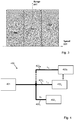
- Figure 4 illustrates an example MIMO radar system 400 with a single transmitter 401 providing signals to a plurality of antennas 402 1-N along a corresponding plurality of signal paths 403 1-N .
- the length L 1-N of each signal path 403 1-N is dependent on the required phase difference for signals provided to each antenna 402 1-N .
- N is the number of signal paths and the corresponding number of antennas and transmission signals.
- FIG. 5 schematically illustrates N transmission signals TX1-TXN, each comprising M chirps, chirp1 to chirpM. Successive chirps in each transmission signal are offset in frequency such that chirpm in each transmission signal is offset by ⁇ F(m-1), where ⁇ F is the offset between successive chirps and m is an integer from 1 to M. Each chirp also has a phase shift of (m-1)(n-1)*360°/N, where n is an integer from 1 to N.
- Table 2 below provides a summary of the relationships between the lengths of antenna feed lines L 1 to L N and chirps 1 to M provided to each of the antennas at centre frequencies F 1 to F M .
- phase shift boundary conditions for the remaining antenna feed lines provides a complete set of equations that are required for the system design.
- the design procedure may begin by defining the frequencies to be used with the different chirps followed by finding the integer values that satisfy all of the required relationships.
- Table 3 provides a set of relationships indicating the length differences between each antenna feed line in terms of the wavelengths of the chirp centre frequencies.
- the lengths and differences in Tables 1 and 2 are illustrated graphically in Figure 6 for antenna feed lines 403 1-N .
- B 1 ⁇ 1 B 2 ⁇ 2 + ⁇ 2 N
- B 1 B 2 + 1 N ⁇ ⁇ 2 ⁇ 1
- B 1 ⁇ 1 B 3 ⁇ 3 + 2.
- N ⁇ 1 . ⁇ 3 N N 1 N 3 + 2.
- N ⁇ 1 N ⁇ ⁇ 3 ⁇ 1 N 1 ⁇ 1 N M ⁇ M + M ⁇ 1 . N ⁇ 1 .
- Y [1 to N] A XY ⁇ X + (Y-1) *(X-1) ⁇ X /N ...
- the length L 1 may be replaced with any length. This creates a mismatch in phase in a reference plan 701 at the end of L 1 between chirps due the frequency shift introduced, i.e. the point in the waveguide used to define the phase within and between the channels.
- the phase reference plan at the end of L 1 can be adjusted by using the TX phase rotator.
- Figure 7 illustrates schematically a series of antenna feeds 703 1-N of lengths L 1-N .
- Table 4 indicates the phase in the reference plan using L 1 .
- Table 5 indicates the phase in the reference plan for an arbitrary length L Z .
- Table 6 indicates the phase in the reference plan for L Z with opposite phase rotation, i.e. -E° for F1, -F° for F2 and -G° for F3.
- Table 5 Phase extraction at the reference plan for antenna feed length L 1 .
- Table 7 Phase extraction at the reference plan for an arbitrary length L Z with opposite phase rotator correction.
- the first step is to define the frequency difference ⁇ F between successive chirps.
- Figure 8 is a flow chart illustrating an example method of designing a DDM MIMO radar system 400 of Figure 4 , the system 400 having N antennas 402 1-N connected to a transmitter 401 via N signal paths 403 1-N having lengths L 1-N .
- a first step 801 a series of M frequencies separated by a frequency difference ⁇ F and having wavelengths ⁇ 1-M are defined. These frequencies define the centre frequencies of the series of chirps to be transmitted in each radar cycle frame.
- a length L 1 of a first one 403 1 of the N signal paths 403 1-N is determined.
- the length L 1 may be determined arbitrarily or may be determined as A m1 ⁇ m , where A m1 is an integer and ⁇ m is a wavelength of an m th one of the series of M frequencies.
- the lengths of each of the signal paths between the transmitter and the N antennas are thereby defined such that a phase of a signal transmitted by the transmitter 401 is different at each of the plurality of transmitter antennas 402 1-N .
Landscapes
- Engineering & Computer Science (AREA)
- Radar, Positioning & Navigation (AREA)
- Remote Sensing (AREA)
- Computer Networks & Wireless Communication (AREA)
- Physics & Mathematics (AREA)
- General Physics & Mathematics (AREA)
- Radar Systems Or Details Thereof (AREA)
Abstract
Description
- The disclosure relates to a doppler division multiplexing MIMO radar system.
- Modern automotive radar systems require a high angular resolution. This may be achieved in two different ways. A first is to use a phased antenna array and to perform beamforming, in which multiple transmitters are combined with different phases to steer a beam. A second is to implement multiple input multiple output (MIMO) radar to create virtual antennas. For both strategies, however, a system with multiple transmitters and receivers is required. This results in the area, power consumption and power dissipation required to implement such systems at monolithic level eventually becoming prohibitive as the number of required channels grows in order to achieve higher angular resolution.
- For MIMO radar systems, there is a requirement to use orthogonal signals for each transmitter channel to be able to reconstruct the information at the receiver. One way of achieving orthogonality between channels in automotive radar is by using doppler domain multiplexing (DDM) techniques. In DDM, frequency modulated signals are used and a frequency delta created between transmitter channels. Each channel can be identified at the receiver because it will fall in a different band frequency in the doppler spectrum. One way to generate the delta frequencies between channels is by changing phase from chirp to chirp with a defined sequence. A phase rotator at the transmitter is required to achieve this.
- A problem with existing DDM MIMO radar is that multiple transmitter channels are required, which occupy increased area and increase the cost and power consumption of the system. A further problem is that accurate control of phase shifts between the transmitted channels is difficult using digital techniques.
- According to a first aspect there is provided a doppler division multiplexing, DDM, multiple input multiple output, MIMO, radar system comprising a transmitter connected to a plurality of transmitter antennas via a corresponding plurality of signal paths of different electrical lengths such that a phase of a signal transmitted by the transmitter is different at each of the plurality of transmitter antennas.
- The transmitter may be configured to generate a series of M chirps in a radar cycle frame provided to each of the plurality of N transmitter antennas. Each of the N signal paths may have a length Ln such that a phase difference between an mth chirp in the radar cycle frame at an nth antenna and the mth chirp at a first antenna is equal to (m-1)(n-1)*360/N.
- A length L1 of a first one of the N signal paths may be equal to Am1λm. where Am1 is an integer and λm is a wavelength of a centre frequency of an mth chirp in the radar cycle frame.
- A difference in length between an nth signal path and the first one of the N signal paths may be equal to Xnλn+(n-1)(n-1)λn/n, where Xn is an integer corresponding to the antenna number.
- Where each chirp in the series of M chirps has a center frequency, the center frequency may change by a frequency difference ΔF between successive chirps.
- According to a second aspect there is provided a method of designing a DDM MIMO radar system having N antennas connected to a transmitter via N signal paths having lengths L1-N, the method comprising:
- defining a series of M frequencies separated by a frequency difference ΔF and having wavelengths λ1-M;
- determining a length L1 of a first one of the N signal paths;
- determining a difference in length between the first one of the N signal paths and an nth signal path as Xnλn+(n-1)(n-1)λn/n, where Xn is an integer.
- In some examples the length of the first one of the N signal paths may be determined as Am1λm, where Am1 is an integer and λm is a wavelength of an mth one of the series of M frequencies. In such examples the phase difference at the first antenna will be zero. In other examples the length of the first signal path may be determined to be an arbitrary length and the difference between this and the other lengths determined. The phase at the first antenna can then be selected to be zero by rotating the phase of the output of the transmitter during operation.
- According to a third aspect there is provided a method of operating a doppler division multiplexing, DDM, multiple input multiple output, MIMO, radar system comprising a transmitter connected to a plurality of N transmitter antennas via a corresponding plurality of signal paths of different electrical lengths, the method comprising the transmitter generating a series of M chirps in a radar cycle frame provided to each of the plurality of N antennas.
- Each of the N signal paths may have a length Ln such that a phase difference between an mth chirp in the radar cycle frame at an nth antenna and the mth chirp at a first antenna is equal to (m-1)(n-1)*360/N. Other features relating to the first aspect may also apply to the method of the second aspect.
- According to the first aspect, one transmitter is connected to multiple antennas with a different electrical length of the feeding structure and a central frequency of the chirp is changed from chirp to chirp. With this combination, a phase difference between chirps and between antennas will be generated which at the same time will generate the required effect to code every transmit channel in a different doppler band. In this way, only one TX channel is required to create a MIMO system. Energy, power dissipation and chip area can thereby be reduced. An additional advantage is that the phase shift for each transmitter can be designed precisely in contrast to the phase shifter in conventional RF chips which are controlled digitally and tend to have large error values (typically ±6°) which deteriorates the performance of the radar system. By using the waveguides instead with differing lengths, the phase shift (and hence the frequency offset for each transmitter) can be set precisely and hence have a better performance and closer to the simulated model of a Doppler division multiplexing algorithm.
- These and other aspects of the invention will be apparent from, and elucidated with reference to, the embodiments described hereinafter.
- Embodiments will be described, by way of example only, with reference to the drawings, in which:
-
Figure 1 is a schematic diagram of doppler domain multiplexing for three channels; -
Figure 2 is a schematic diagram of a series of chirps from transmitters in a radar cycle frame; -
Figure 3 is a two-dimensional FFT representation for three transmission channels; -
Figure 4 is a schematic diagram of an example MIMO radar system; -
Figure 5 is a schematic diagram of N transmission signals over N transmission channels, each comprising M chirps; -
Figure 6 illustrates different length antenna feed lines; -
Figure 7 further illustrates different antenna feed lines; and -
Figure 8 is a flow diagram illustrating an example method of designing a DDM MIMO radar system. - It should be noted that the Figures are diagrammatic and not drawn to scale. Relative dimensions and proportions of parts of these Figures have been shown exaggerated or reduced in size, for the sake of clarity and convenience in the drawings. The same reference signs are generally used to refer to corresponding or similar feature in modified and different embodiments.
- In doppler domain multiplexing, a frequency difference (or Δf) is provided between multiple channels. The Δf needs to be large enough to be able to locate each channel in a different bandwidth. An example doppler spectrum is illustrated schematically in
Figure 1 , in which three transmission channels TX1, TX2, TX3 are separated by differences in velocity Δv across the spectrum. - To achieve doppler separation between channels, one way is to change the phase of each channel between chirps in a defined sequence. To achieve a channel separation equal to the doppler separation Δf doppler, the phase shift may be expressed as:

- Considering one transmitter driving three antennas, orthogonal code for successive chirps for each transmission channel is shown in Table 1 below. Channel TX1 retains a zero phase modulation, while channels TX2 and TX3 alternate between 120° and 240°.
Table 1: Orthogonal code for successive chirps for phase modulation of three transmission channels. Phase modulation Chirp 1 Chirp 2Chirp 3 Chirp 4 Chirp 5 TX 1 0 0 0 0 0 TX 20 120 240 0 120 TX 3 0 240 120 0 240 -
Figure 2 illustrates an example sequence of chirps over a radar cycle frame, with N successive chirps chirp1-N being transmitted in each transmission channel TX1, TX2, TX3 over the radar cycle frame. For each chirp a frequency shift Δfn is introduced, where n ranges from 1 to N. - Phase modulation of successive chirps creates an offset in the doppler domain, resulting in the different transmission channels being easy to extract. A representation of a two-dimensional FFT in terms of range versus speed for the three transmission channels TX1, TX2, TX3 is shown in
Figure 3 . - Instead of using multiple transmitters, the phase differences between channels and between successive chirps may be generated using a relationship between the length of a feeding structure of each antenna and the centre frequency of each chirp. In this way, with one transmitter connected to multiple antennas it is possible to generate a MIMO radar system.
-
Figure 4 illustrates an exampleMIMO radar system 400 with asingle transmitter 401 providing signals to a plurality of antennas 4021-N along a corresponding plurality ofsignal paths 4031-N. The length L1-N of eachsignal path 4031-N is dependent on the required phase difference for signals provided to each antenna 4021-N. N is the number of signal paths and the corresponding number of antennas and transmission signals. -
Figure 5 schematically illustrates N transmission signals TX1-TXN, each comprising M chirps, chirp1 to chirpM. Successive chirps in each transmission signal are offset in frequency such that chirpm in each transmission signal is offset by ΔF(m-1), where ΔF is the offset between successive chirps and m is an integer from 1 to M. Each chirp also has a phase shift of (m-1)(n-1)*360°/N, where n is an integer from 1 to N. Table 2 below provides a summary of the relationships between the lengths of antenna feed lines L1 to LN and chirps 1 to M provided to each of the antennas at centre frequencies F1 to FM. - The first
antenna feed line 4031 should be provided with a signal having a 0° phase shift, and should therefore have a length L1 that is equal to a multiple of wavelengths of all frequencies used, i.e.:
- The second
antenna feed line 4032 should also provide a progressive phase shift for consecutive frequencies, i.e. at +λ2/N, 2λ3/N, 3λ4/N and so on, i.e.:
- Applying the phase shift boundary conditions for the remaining antenna feed lines provides a complete set of equations that are required for the system design. The design procedure may begin by defining the frequencies to be used with the different chirps followed by finding the integer values that satisfy all of the required relationships.
- Table 3 provides a set of relationships indicating the length differences between each antenna feed line in terms of the wavelengths of the chirp centre frequencies. The lengths and differences in Tables 1 and 2 are illustrated graphically in
Figure 6 for antenna feed lines 4031-N.For L1: 
For L2 - L1: 


For LN - L1: 


Table 2: Calculation of equivalent lengths for N antenna feeds Equivalent length vs frequency Chirp 1: F1 Chirp 2: F2 Chirp 3: F3 ... Chirp N: FN Chirp N+1: FN+1 ... Chirp M: FM L1 A11λ1 A21λ2 A31λ3 ... AN1λN A11λ1 ... AM1λM L2 A12λ1 A22λ2 + λ2/N A32λ3 + 2 λ3/N ... AN2λN + (N-1) λN/N A12λ1 ... AM2λM+ (M-1) λM/N L3 A13λ1 A23λ2+ 2 λ2/N A33λ3 + 4 λ3/N ... AN3λN+ 2*(N-1) λN/N A13λ1 ... AM3λM+ 2*(M-1) λM/N ... ... LY Chirp X X [1 to M] modulo N; Y [1 to N] : AXYλX + (Y-1) *(X-1) λX/N ... LN A1Nλ1 A2Nλ2+(N-1)λ2/N A3Nλ3 + 2*(N-1) λ3/N ... ANNλN+ (N-1)*(N-1) λN/N A1Nλ1 ... AMNλM+ (N-1)*(M-1) λM/N Table 3: Calculation of equivalent length differences for N antenna feeds Equivalent length vs frequency Chirp 1: F1 Chirp 2: F2 Chirp 3: F3 ... Chirp N: FN Chirp N+1: FN+1 ... Chirp M=P*N: FM Where P is an integer L1 A11λ1 A21λ2 A31λ3 ... AN1λN A11λ1 ... AN1λN L2 - L1 B1 λ1 B2 λ2 + λ2/N B3 λ3 +2 λ3/N ... BN λN + (N-1) λN/N B1 λ1 ... BN λN+ (N-1) λN/N L3-L1 C1 λ1 C2 λ2+ 2 λ2/N C3 λ3 + 4 λ3/N ... CN λN+ 2*(N-1) λN/N C1 λ1 ... CN λN+ 2*(N-1) λN/N ... ... ... ... ... ... ... ... ... LN-L1 N1λ1 N2 λ2+(N-1) λ2/N N3 λ3 + 2*(N-1 )λ3/N ... NN λN+ (N-1)*(N-1)λN/N N1λ1 ... NN λN+ (N-1)*(N-1) λN/N - A practical design environment may not allow for sufficient flexibility to choose each antenna feed length. Therefore, to simplify design the length L1 may be replaced with any length. This creates a mismatch in phase in a
reference plan 701 at the end of L1 between chirps due the frequency shift introduced, i.e. the point in the waveguide used to define the phase within and between the channels. The phase reference plan at the end of L1 can be adjusted by using the TX phase rotator.Figure 7 illustrates schematically a series of antenna feeds 7031-N of lengths L1-N. - The phase extractions at the
reference plan 701 are indicated in Tables 4, 5 and 6 below. Table 4 indicates the phase in the reference plan using L1. Table 5 indicates the phase in the reference plan for an arbitrary length LZ. Table 6 indicates the phase in the reference plan for LZ with opposite phase rotation, i.e. -E° for F1, -F° for F2 and -G° for F3.Table 5: Phase extraction at the reference plan for antenna feed length L1. Phase in the reference plan using L1 Chirp1: F1 Chirp2: F2 Chirp3: F3 L1 0° 0° 0° L2 0° 0° 0° L3 0° 0° 0° Table 6: Phase extraction at the reference plan for an arbitrary length LZ. Phase in the reference plan using LZ Chirp1: F1 Chirp2: F2 Chirp3: F3 LZ E° F° G° LZ + L2 - L1 E° F° G° LZ + L3 - L1 E° F° G° Table 7: Phase extraction at the reference plan for an arbitrary length LZ with opposite phase rotator correction. Phase in the reference plan using LZ Chirp1: F1 Chirp2: F2 Chirp3: F3 LZ 0° 0° 0° LZ + L2 - L1 0° 0° 0° LZ + L3 - L1 0° 0° 0° - To take an example embodiment where N=2, i.e. a single transmitter is driving only two antennas, the first step is to define the frequency difference ΔF between successive chirps. In this example, ΔF is defined as 5%. This may then be input into the equations mentioned above and the resulting calculations are:


- This equation has multiple solutions as there are two unknowns and only one relationship between B1 and B2. Given that B1 and B2 are integers, the smallest solution, which limits the design constraints, is B1=10 and B2=10, which results in:


- This provides some critical constraint to the hardware design. The simplification concept as described above may be applied to reduce significantly the different lengths L1 and L2 except the delta L which is fixed and required for the concept.

- For this we have to determine the new phase for both frequencies f1 and f2.
Forf1 
- This is an integer number of lambdas, so the reference phase is still 0°
Forf2 
- This is an integer number of lambdas plus half one, so the reference phase is 180°
- Between both frequencies f1 and f2 the TX phase has to be shifted by 180° to keep the phase coherency of the system.
-
Figure 8 is a flow chart illustrating an example method of designing a DDMMIMO radar system 400 ofFigure 4 , thesystem 400 having N antennas 4021-N connected to atransmitter 401 viaN signal paths 4031-N having lengths L1-N. In a first step 801 a series of M frequencies separated by a frequency difference ΔF and having wavelengths λ1-M are defined. These frequencies define the centre frequencies of the series of chirps to be transmitted in each radar cycle frame. In asecond step 802, a length L1 of a first one 4031 of theN signal paths 4031-N is determined. The length L1 may be determined arbitrarily or may be determined as Am1λm, where Am1 is an integer and λm is a wavelength of an mth one of the series of M frequencies. In athird step 803, a difference in length between the first one 4031 of theN signal paths 4031-N and an nth signal path as Xnλn+(n-1)(n-1)λn/n, where Xn is an integer, is determined. The lengths of each of the signal paths between the transmitter and the N antennas are thereby defined such that a phase of a signal transmitted by thetransmitter 401 is different at each of the plurality of transmitter antennas 4021-N. - From reading the present disclosure, other variations and modifications will be apparent to the skilled person. Such variations and modifications may involve equivalent and other features which are already known in the art of memory systems, and which may be used instead of, or in addition to, features already described herein.
- Although the appended claims are directed to particular combinations of features, it should be understood that the scope of the disclosure of the present invention also includes any novel feature or any novel combination of features disclosed herein either explicitly or implicitly or any generalisation thereof, whether or not it relates to the same invention as presently claimed in any claim and whether or not it mitigates any or all of the same technical problems as does the present invention.
- Features which are described in the context of separate embodiments may also be provided in combination in a single embodiment. Conversely, various features which are, for brevity, described in the context of a single embodiment, may also be provided separately or in any suitable sub-combination. The applicant hereby gives notice that new claims may be formulated to such features and/or combinations of such features during the prosecution of the present application or of any further application derived therefrom.
- For the sake of completeness it is also stated that the term "comprising" does not exclude other elements or steps, the term "a" or "an" does not exclude a plurality, a single processor or other unit may fulfil the functions of several means recited in the claims and reference signs in the claims shall not be construed as limiting the scope of the claims.
Claims (13)
- A doppler division multiplexing, DDM, multiple input multiple output, MIMO, radar system (400) comprising a transmitter (401) connected to a plurality of transmitter antennas (4021-N) via a corresponding plurality of signal paths (4031-N) of different electrical lengths (L1-N) such that a phase of a signal transmitted by the transmitter (401) is different at each of the plurality of transmitter antennas (4021-N).
- The radar system (400) of claim 1, wherein the transmitter (401) is configured to generate a series of M chirps (chirp1-M) in a radar cycle frame provided to each of the plurality of N transmitter antennas (4021-N).
- The radar system (400) of claim 2, wherein each of the N signal paths has a length Ln such that a phase difference between an mth chirp in the radar cycle frame at an nth antenna and the mth chirp at a first antenna is equal to (m-1)(n-1)*360/N.
- The radar system (400) of claim 3, wherein a length L1 of a first one of the N signal paths is equal to Am1λm. where Am1 is an integer and λm is a wavelength of a centre frequency of an mth chirp in the radar cycle frame.
- The radar system (400) of any preceding claim, wherein a difference in length between an nth signal path and a first one of the N signal paths is equal to Xnλn+(n-1)(n-1)λn/n, where Xn is an integer corresponding to a number of each antenna.
- The radar system (400) of any of claims 2 to 5, wherein each chirp in the series of M chirps has a center frequency, the center frequency changing by a frequency difference ΔF between successive chirps.
- A method of designing a DDM MIMO radar system having N antennas (4021-N) connected to a transmitter (401) via N signal paths (4031-N) having lengths L1-N, the method comprising:defining a series of M frequencies separated by a frequency difference ΔF and having wavelengths λ1-M;determining a length L1 of a first one (4031) of the N signal paths (4031-N);determining a difference in length between the first one (4031) of the N signal paths (4031-N) and an nth signal path as Xnλn+(n-1)(n-1)λn/n, where Xn is an integer.
- The method of claim 7, wherein the length L1 of the first one (4031) of the N signal paths (4031-N) is determined as Am1λm, where Am1 is an integer and λm is a wavelength of an mth one of the series of M frequencies.
- A method of operating a doppler division multiplexing, DDM, multiple input multiple output, MIMO, radar system (400) comprising a transmitter (401) connected to a plurality of N transmitter antennas (4021-N) via a corresponding plurality of signal paths (4031-N) of different electrical lengths (L1-N), the method comprising the transmitter (401) generating a series of M chirps in a radar cycle frame provided to each of the plurality of N antennas (4021-N).
- The method of claim 9, wherein each of the N signal paths has a length Ln such that a phase difference between an mth chirp in the radar cycle frame at an nth antenna and the mth chirp at a first antenna is equal to (m-1)(n-1)*360/N.
- The method of claim 9 or claim 10, wherein a length L1 of a first one of the N signal paths is equal to Am1λm. where Am1 is an integer and λm is a wavelength of a centre frequency of an mth chirp in the radar cycle frame.
- The method of any one of claims 9 to 11, wherein a difference in length between an nth signal path and a first one of the N signal paths is equal to Xnλn+(n-1)(n-1)λn/n, where Xn is an integer corresponding to a number of each antenna.
- The method of any one of claims 9 to 12, wherein each chirp in the series of M chirps has a center frequency, the center frequency changing by a frequency difference ΔF between successive chirps.
Priority Applications (3)
| Application Number | Priority Date | Filing Date | Title |
|---|---|---|---|
| EP20182372.1A EP3929622B1 (en) | 2020-06-25 | 2020-06-25 | Radar system |
| US17/347,878 US11988768B2 (en) | 2020-06-25 | 2021-06-15 | Radar system |
| CN202110698296.9A CN113848530A (en) | 2020-06-25 | 2021-06-23 | radar system |
Applications Claiming Priority (1)
| Application Number | Priority Date | Filing Date | Title |
|---|---|---|---|
| EP20182372.1A EP3929622B1 (en) | 2020-06-25 | 2020-06-25 | Radar system |
Publications (2)
| Publication Number | Publication Date |
|---|---|
| EP3929622A1 true EP3929622A1 (en) | 2021-12-29 |
| EP3929622B1 EP3929622B1 (en) | 2024-08-07 |
Family
ID=71170353
Family Applications (1)
| Application Number | Title | Priority Date | Filing Date |
|---|---|---|---|
| EP20182372.1A Active EP3929622B1 (en) | 2020-06-25 | 2020-06-25 | Radar system |
Country Status (3)
| Country | Link |
|---|---|
| US (1) | US11988768B2 (en) |
| EP (1) | EP3929622B1 (en) |
| CN (1) | CN113848530A (en) |
Cited By (3)
| Publication number | Priority date | Publication date | Assignee | Title |
|---|---|---|---|---|
| US20230129203A1 (en) * | 2021-10-26 | 2023-04-27 | Infineon Technologies Ag | Doppler-division multiplexing mimo radar signal reconstruction |
| DE102022106791A1 (en) | 2022-03-23 | 2023-09-28 | Infineon Technologies Ag | MIMO RADAR DEVICE AND MIMO RADAR METHOD |
| CN119986574A (en) * | 2023-11-01 | 2025-05-13 | 加特兰微电子科技(上海)有限公司 | Signal processing method, storage medium, radar chip and integrated circuit |
Families Citing this family (5)
| Publication number | Priority date | Publication date | Assignee | Title |
|---|---|---|---|---|
| US12360229B2 (en) * | 2021-08-06 | 2025-07-15 | Panasonic Automotive Systems Co., Ltd. | Radar apparatus |
| US12537317B2 (en) | 2022-04-19 | 2026-01-27 | Nxp B.V. | Dual polarized antenna with dual feed and cross polarization isolation |
| JP7780418B2 (en) * | 2022-12-19 | 2025-12-04 | パナソニックオートモーティブシステムズ株式会社 | Radar device, radar signal transmission method, and radar signal generation device |
| JP2025176511A (en) * | 2024-05-21 | 2025-12-04 | 株式会社デンソー | Radar system, radar control device, radar control method, and radar control program |
| WO2026034381A1 (en) * | 2024-08-07 | 2026-02-12 | 株式会社デンソー | Radar system, radar control device, radar control method, and radar control program |
Citations (2)
| Publication number | Priority date | Publication date | Assignee | Title |
|---|---|---|---|---|
| WO2019054504A1 (en) * | 2017-09-15 | 2019-03-21 | 株式会社デンソー | Radar device |
| EP3611538A1 (en) * | 2018-08-13 | 2020-02-19 | Nxp B.V. | Mimo radar coding for resolving velocity ambiguity |
Family Cites Families (11)
| Publication number | Priority date | Publication date | Assignee | Title |
|---|---|---|---|---|
| US6937108B2 (en) | 2003-03-11 | 2005-08-30 | M/A-Com, Inc. | Methods and apparatus for offset chirp modulation |
| CN104849711A (en) * | 2015-04-22 | 2015-08-19 | 大连理工大学 | Doppler Compensation Method of I-OFDM MIMO Radar Signal Based on Frequency Domain |
| US11073611B2 (en) | 2017-03-20 | 2021-07-27 | International Business Machines Corporation | High spatial resolution 3D radar based on a single sensor |
| US10723299B2 (en) * | 2017-05-18 | 2020-07-28 | Srg Global Inc. | Vehicle body components comprising retroreflectors and their methods of manufacture |
| EP3428679B1 (en) * | 2017-07-11 | 2021-11-17 | Nxp B.V. | Radar system |
| US20190056478A1 (en) * | 2017-08-15 | 2019-02-21 | Valeo Radar Systems, Inc. | Frequency Domain MIMO For FMCW Radar |
| DE102018207718A1 (en) * | 2018-05-17 | 2019-11-21 | Robert Bosch Gmbh | Method for phase calibration of high-frequency components of a radar sensor |
| DE102018121987A1 (en) * | 2018-09-10 | 2020-03-12 | Infineon Technologies Ag | Frequency modulated continuous wave radar system |
| WO2020083036A1 (en) * | 2018-10-25 | 2020-04-30 | Huawei Technologies Co., Ltd. | Improved radar systems and methods |
| KR102746695B1 (en) * | 2019-02-01 | 2024-12-26 | 주식회사 에이치엘클레무브 | Radar Sensor Apparatus for Vehicle and Object Detecting Method, Antenna Apparatus therefor |
| CN111308435B (en) * | 2019-12-09 | 2023-04-25 | 中国科学院沈阳自动化研究所 | A centralized MIMO radar signal processing method with variable carrier frequency and multiple delays |
-
2020
- 2020-06-25 EP EP20182372.1A patent/EP3929622B1/en active Active
-
2021
- 2021-06-15 US US17/347,878 patent/US11988768B2/en active Active
- 2021-06-23 CN CN202110698296.9A patent/CN113848530A/en active Pending
Patent Citations (3)
| Publication number | Priority date | Publication date | Assignee | Title |
|---|---|---|---|---|
| WO2019054504A1 (en) * | 2017-09-15 | 2019-03-21 | 株式会社デンソー | Radar device |
| US20200209380A1 (en) * | 2017-09-15 | 2020-07-02 | Denso Corporation | Radar device |
| EP3611538A1 (en) * | 2018-08-13 | 2020-02-19 | Nxp B.V. | Mimo radar coding for resolving velocity ambiguity |
Non-Patent Citations (1)
| Title |
|---|
| YANG FAWEI ET AL: "DDMA MIMO radar system for low, slow, and small target detection", THE JOURNAL OF ENGINEERING, THE INSTITUTION OF ENGINEERING AND TECHNOLOGY, MICHAEL FARADAY HOUSE, SIX HILLS WAY, STEVENAGE, HERTS. SG1 2AY, UK, vol. 2019, no. 19, 1 October 2019 (2019-10-01), pages 5932 - 5935, XP006085865, DOI: 10.1049/JOE.2019.0212 * |
Cited By (5)
| Publication number | Priority date | Publication date | Assignee | Title |
|---|---|---|---|---|
| US20230129203A1 (en) * | 2021-10-26 | 2023-04-27 | Infineon Technologies Ag | Doppler-division multiplexing mimo radar signal reconstruction |
| US12007467B2 (en) * | 2021-10-26 | 2024-06-11 | Infineon Technologies Ag | Doppler-division multiplexing MIMO radar signal reconstruction |
| DE102022106791A1 (en) | 2022-03-23 | 2023-09-28 | Infineon Technologies Ag | MIMO RADAR DEVICE AND MIMO RADAR METHOD |
| US12578425B2 (en) | 2022-03-23 | 2026-03-17 | Infineon Technologies Ag | MIMO radar apparatus and MIMO radar method |
| CN119986574A (en) * | 2023-11-01 | 2025-05-13 | 加特兰微电子科技(上海)有限公司 | Signal processing method, storage medium, radar chip and integrated circuit |
Also Published As
| Publication number | Publication date |
|---|---|
| EP3929622B1 (en) | 2024-08-07 |
| US11988768B2 (en) | 2024-05-21 |
| CN113848530A (en) | 2021-12-28 |
| US20210405151A1 (en) | 2021-12-30 |
Similar Documents
| Publication | Publication Date | Title |
|---|---|---|
| EP3929622B1 (en) | Radar system | |
| EP2291885B1 (en) | Calibrating radiofrequency paths of a phased-array antenna | |
| EP4012938B1 (en) | Method and device for correcting multiple channels of digital-analog hybrid beamforming | |
| EP1464986B1 (en) | Radar apparatus | |
| US7898465B2 (en) | Electronically scanned radar system and receiving antenna | |
| US5248982A (en) | Method and apparatus for calibrating phased array receiving antennas | |
| WO2007083479A1 (en) | Radar apparatus | |
| EP2989683B1 (en) | Low cost active antenna system | |
| US12405353B2 (en) | Radar device | |
| US11070283B2 (en) | System for calibrating from the ground a payload of a satellite | |
| EP0152482B1 (en) | Direction finding interferometer internal calibration system | |
| EP4035274B1 (en) | Phased array antenna system | |
| US20240372268A1 (en) | Multiple input multiple output radar, antenna arrays and transmission schemes | |
| US20220321161A1 (en) | Antenna wireless device | |
| US20170176573A1 (en) | Aperture coding for a single aperture transmit receive system | |
| SE508113C2 (en) | Transmitter interference removal | |
| CN116679292B (en) | A radar, a radar channel separation method and apparatus | |
| KR102844923B1 (en) | SC-OFDM radar transmitter, transmission method and system | |
| US12366652B2 (en) | Apparatus and method for controlling radar in vehicle | |
| JP2007240445A (en) | Radar system | |
| EP4610690A1 (en) | Radar unit, circuit for a radar transceiver and method therefor | |
| GB2595691A (en) | Antenna array | |
| RU1840917C (en) | Device for phase calibration of multichannel receiver | |
| DE102023203974A1 (en) | Radar device and method for operating a radar device | |
| EP3993282A1 (en) | A communications system |
Legal Events
| Date | Code | Title | Description |
|---|---|---|---|
| PUAI | Public reference made under article 153(3) epc to a published international application that has entered the european phase |
Free format text: ORIGINAL CODE: 0009012 |
|
| STAA | Information on the status of an ep patent application or granted ep patent |
Free format text: STATUS: THE APPLICATION HAS BEEN PUBLISHED |
|
| AK | Designated contracting states |
Kind code of ref document: A1 Designated state(s): AL AT BE BG CH CY CZ DE DK EE ES FI FR GB GR HR HU IE IS IT LI LT LU LV MC MK MT NL NO PL PT RO RS SE SI SK SM TR |
|
| B565 | Issuance of search results under rule 164(2) epc |
Effective date: 20201221 |
|
| STAA | Information on the status of an ep patent application or granted ep patent |
Free format text: STATUS: REQUEST FOR EXAMINATION WAS MADE |
|
| 17P | Request for examination filed |
Effective date: 20220629 |
|
| RBV | Designated contracting states (corrected) |
Designated state(s): AL AT BE BG CH CY CZ DE DK EE ES FI FR GB GR HR HU IE IS IT LI LT LU LV MC MK MT NL NO PL PT RO RS SE SI SK SM TR |
|
| GRAP | Despatch of communication of intention to grant a patent |
Free format text: ORIGINAL CODE: EPIDOSNIGR1 |
|
| STAA | Information on the status of an ep patent application or granted ep patent |
Free format text: STATUS: GRANT OF PATENT IS INTENDED |
|
| INTG | Intention to grant announced |
Effective date: 20240322 |
|
| GRAS | Grant fee paid |
Free format text: ORIGINAL CODE: EPIDOSNIGR3 |
|
| GRAA | (expected) grant |
Free format text: ORIGINAL CODE: 0009210 |
|
| STAA | Information on the status of an ep patent application or granted ep patent |
Free format text: STATUS: THE PATENT HAS BEEN GRANTED |
|
| AK | Designated contracting states |
Kind code of ref document: B1 Designated state(s): AL AT BE BG CH CY CZ DE DK EE ES FI FR GB GR HR HU IE IS IT LI LT LU LV MC MK MT NL NO PL PT RO RS SE SI SK SM TR |
|
| REG | Reference to a national code |
Ref country code: GB Ref legal event code: FG4D |
|
| REG | Reference to a national code |
Ref country code: CH Ref legal event code: EP |
|
| REG | Reference to a national code |
Ref country code: DE Ref legal event code: R096 Ref document number: 602020035188 Country of ref document: DE |
|
| REG | Reference to a national code |
Ref country code: IE Ref legal event code: FG4D |
|
| REG | Reference to a national code |
Ref country code: LT Ref legal event code: MG9D |
|
| REG | Reference to a national code |
Ref country code: NL Ref legal event code: MP Effective date: 20240807 |
|
| PG25 | Lapsed in a contracting state [announced via postgrant information from national office to epo] |
Ref country code: NO Free format text: LAPSE BECAUSE OF FAILURE TO SUBMIT A TRANSLATION OF THE DESCRIPTION OR TO PAY THE FEE WITHIN THE PRESCRIBED TIME-LIMIT Effective date: 20241107 |
|
| REG | Reference to a national code |
Ref country code: AT Ref legal event code: MK05 Ref document number: 1711549 Country of ref document: AT Kind code of ref document: T Effective date: 20240807 |
|
| PG25 | Lapsed in a contracting state [announced via postgrant information from national office to epo] |
Ref country code: NL Free format text: LAPSE BECAUSE OF FAILURE TO SUBMIT A TRANSLATION OF THE DESCRIPTION OR TO PAY THE FEE WITHIN THE PRESCRIBED TIME-LIMIT Effective date: 20240807 Ref country code: FI Free format text: LAPSE BECAUSE OF FAILURE TO SUBMIT A TRANSLATION OF THE DESCRIPTION OR TO PAY THE FEE WITHIN THE PRESCRIBED TIME-LIMIT Effective date: 20240807 Ref country code: PT Free format text: LAPSE BECAUSE OF FAILURE TO SUBMIT A TRANSLATION OF THE DESCRIPTION OR TO PAY THE FEE WITHIN THE PRESCRIBED TIME-LIMIT Effective date: 20241209 Ref country code: PL Free format text: LAPSE BECAUSE OF FAILURE TO SUBMIT A TRANSLATION OF THE DESCRIPTION OR TO PAY THE FEE WITHIN THE PRESCRIBED TIME-LIMIT Effective date: 20240807 Ref country code: GR Free format text: LAPSE BECAUSE OF FAILURE TO SUBMIT A TRANSLATION OF THE DESCRIPTION OR TO PAY THE FEE WITHIN THE PRESCRIBED TIME-LIMIT Effective date: 20241108 |
|
| PG25 | Lapsed in a contracting state [announced via postgrant information from national office to epo] |
Ref country code: BG Free format text: LAPSE BECAUSE OF FAILURE TO SUBMIT A TRANSLATION OF THE DESCRIPTION OR TO PAY THE FEE WITHIN THE PRESCRIBED TIME-LIMIT Effective date: 20240807 |
|
| PG25 | Lapsed in a contracting state [announced via postgrant information from national office to epo] |
Ref country code: LV Free format text: LAPSE BECAUSE OF FAILURE TO SUBMIT A TRANSLATION OF THE DESCRIPTION OR TO PAY THE FEE WITHIN THE PRESCRIBED TIME-LIMIT Effective date: 20240807 |
|
| PG25 | Lapsed in a contracting state [announced via postgrant information from national office to epo] |
Ref country code: AT Free format text: LAPSE BECAUSE OF FAILURE TO SUBMIT A TRANSLATION OF THE DESCRIPTION OR TO PAY THE FEE WITHIN THE PRESCRIBED TIME-LIMIT Effective date: 20240807 Ref country code: IS Free format text: LAPSE BECAUSE OF FAILURE TO SUBMIT A TRANSLATION OF THE DESCRIPTION OR TO PAY THE FEE WITHIN THE PRESCRIBED TIME-LIMIT Effective date: 20241207 |
|
| PG25 | Lapsed in a contracting state [announced via postgrant information from national office to epo] |
Ref country code: HR Free format text: LAPSE BECAUSE OF FAILURE TO SUBMIT A TRANSLATION OF THE DESCRIPTION OR TO PAY THE FEE WITHIN THE PRESCRIBED TIME-LIMIT Effective date: 20240807 |
|
| PG25 | Lapsed in a contracting state [announced via postgrant information from national office to epo] |
Ref country code: ES Free format text: LAPSE BECAUSE OF FAILURE TO SUBMIT A TRANSLATION OF THE DESCRIPTION OR TO PAY THE FEE WITHIN THE PRESCRIBED TIME-LIMIT Effective date: 20240807 Ref country code: RS Free format text: LAPSE BECAUSE OF FAILURE TO SUBMIT A TRANSLATION OF THE DESCRIPTION OR TO PAY THE FEE WITHIN THE PRESCRIBED TIME-LIMIT Effective date: 20241107 |
|
| PG25 | Lapsed in a contracting state [announced via postgrant information from national office to epo] |
Ref country code: RS Free format text: LAPSE BECAUSE OF FAILURE TO SUBMIT A TRANSLATION OF THE DESCRIPTION OR TO PAY THE FEE WITHIN THE PRESCRIBED TIME-LIMIT Effective date: 20241107 Ref country code: PT Free format text: LAPSE BECAUSE OF FAILURE TO SUBMIT A TRANSLATION OF THE DESCRIPTION OR TO PAY THE FEE WITHIN THE PRESCRIBED TIME-LIMIT Effective date: 20241209 Ref country code: PL Free format text: LAPSE BECAUSE OF FAILURE TO SUBMIT A TRANSLATION OF THE DESCRIPTION OR TO PAY THE FEE WITHIN THE PRESCRIBED TIME-LIMIT Effective date: 20240807 Ref country code: NO Free format text: LAPSE BECAUSE OF FAILURE TO SUBMIT A TRANSLATION OF THE DESCRIPTION OR TO PAY THE FEE WITHIN THE PRESCRIBED TIME-LIMIT Effective date: 20241107 Ref country code: NL Free format text: LAPSE BECAUSE OF FAILURE TO SUBMIT A TRANSLATION OF THE DESCRIPTION OR TO PAY THE FEE WITHIN THE PRESCRIBED TIME-LIMIT Effective date: 20240807 Ref country code: LV Free format text: LAPSE BECAUSE OF FAILURE TO SUBMIT A TRANSLATION OF THE DESCRIPTION OR TO PAY THE FEE WITHIN THE PRESCRIBED TIME-LIMIT Effective date: 20240807 Ref country code: IS Free format text: LAPSE BECAUSE OF FAILURE TO SUBMIT A TRANSLATION OF THE DESCRIPTION OR TO PAY THE FEE WITHIN THE PRESCRIBED TIME-LIMIT Effective date: 20241207 Ref country code: HR Free format text: LAPSE BECAUSE OF FAILURE TO SUBMIT A TRANSLATION OF THE DESCRIPTION OR TO PAY THE FEE WITHIN THE PRESCRIBED TIME-LIMIT Effective date: 20240807 Ref country code: GR Free format text: LAPSE BECAUSE OF FAILURE TO SUBMIT A TRANSLATION OF THE DESCRIPTION OR TO PAY THE FEE WITHIN THE PRESCRIBED TIME-LIMIT Effective date: 20241108 Ref country code: FI Free format text: LAPSE BECAUSE OF FAILURE TO SUBMIT A TRANSLATION OF THE DESCRIPTION OR TO PAY THE FEE WITHIN THE PRESCRIBED TIME-LIMIT Effective date: 20240807 Ref country code: ES Free format text: LAPSE BECAUSE OF FAILURE TO SUBMIT A TRANSLATION OF THE DESCRIPTION OR TO PAY THE FEE WITHIN THE PRESCRIBED TIME-LIMIT Effective date: 20240807 Ref country code: BG Free format text: LAPSE BECAUSE OF FAILURE TO SUBMIT A TRANSLATION OF THE DESCRIPTION OR TO PAY THE FEE WITHIN THE PRESCRIBED TIME-LIMIT Effective date: 20240807 Ref country code: AT Free format text: LAPSE BECAUSE OF FAILURE TO SUBMIT A TRANSLATION OF THE DESCRIPTION OR TO PAY THE FEE WITHIN THE PRESCRIBED TIME-LIMIT Effective date: 20240807 |
|
| PG25 | Lapsed in a contracting state [announced via postgrant information from national office to epo] |
Ref country code: DK Free format text: LAPSE BECAUSE OF FAILURE TO SUBMIT A TRANSLATION OF THE DESCRIPTION OR TO PAY THE FEE WITHIN THE PRESCRIBED TIME-LIMIT Effective date: 20240807 Ref country code: SM Free format text: LAPSE BECAUSE OF FAILURE TO SUBMIT A TRANSLATION OF THE DESCRIPTION OR TO PAY THE FEE WITHIN THE PRESCRIBED TIME-LIMIT Effective date: 20240807 |
|
| PG25 | Lapsed in a contracting state [announced via postgrant information from national office to epo] |
Ref country code: EE Free format text: LAPSE BECAUSE OF FAILURE TO SUBMIT A TRANSLATION OF THE DESCRIPTION OR TO PAY THE FEE WITHIN THE PRESCRIBED TIME-LIMIT Effective date: 20240807 |
|
| PG25 | Lapsed in a contracting state [announced via postgrant information from national office to epo] |
Ref country code: CZ Free format text: LAPSE BECAUSE OF FAILURE TO SUBMIT A TRANSLATION OF THE DESCRIPTION OR TO PAY THE FEE WITHIN THE PRESCRIBED TIME-LIMIT Effective date: 20240807 |
|
| PG25 | Lapsed in a contracting state [announced via postgrant information from national office to epo] |
Ref country code: SK Free format text: LAPSE BECAUSE OF FAILURE TO SUBMIT A TRANSLATION OF THE DESCRIPTION OR TO PAY THE FEE WITHIN THE PRESCRIBED TIME-LIMIT Effective date: 20240807 |
|
| REG | Reference to a national code |
Ref country code: DE Ref legal event code: R097 Ref document number: 602020035188 Country of ref document: DE |
|
| PLBE | No opposition filed within time limit |
Free format text: ORIGINAL CODE: 0009261 |
|
| STAA | Information on the status of an ep patent application or granted ep patent |
Free format text: STATUS: NO OPPOSITION FILED WITHIN TIME LIMIT |
|
| PGFP | Annual fee paid to national office [announced via postgrant information from national office to epo] |
Ref country code: DE Payment date: 20250520 Year of fee payment: 6 |
|
| 26N | No opposition filed |
Effective date: 20250508 |
|
| PGFP | Annual fee paid to national office [announced via postgrant information from national office to epo] |
Ref country code: FR Payment date: 20250520 Year of fee payment: 6 |
|
| P01 | Opt-out of the competence of the unified patent court (upc) registered |
Free format text: CASE NUMBER: APP_29905/2025 Effective date: 20250623 |
|
| PG25 | Lapsed in a contracting state [announced via postgrant information from national office to epo] |
Ref country code: SE Free format text: LAPSE BECAUSE OF FAILURE TO SUBMIT A TRANSLATION OF THE DESCRIPTION OR TO PAY THE FEE WITHIN THE PRESCRIBED TIME-LIMIT Effective date: 20240807 |
|
| REG | Reference to a national code |
Ref country code: CH Ref legal event code: H13 Free format text: ST27 STATUS EVENT CODE: U-0-0-H10-H13 (AS PROVIDED BY THE NATIONAL OFFICE) Effective date: 20260127 |
|
| PG25 | Lapsed in a contracting state [announced via postgrant information from national office to epo] |
Ref country code: IT Free format text: LAPSE BECAUSE OF FAILURE TO SUBMIT A TRANSLATION OF THE DESCRIPTION OR TO PAY THE FEE WITHIN THE PRESCRIBED TIME-LIMIT Effective date: 20240807 |
|
| PG25 | Lapsed in a contracting state [announced via postgrant information from national office to epo] |
Ref country code: MC Free format text: LAPSE BECAUSE OF FAILURE TO SUBMIT A TRANSLATION OF THE DESCRIPTION OR TO PAY THE FEE WITHIN THE PRESCRIBED TIME-LIMIT Effective date: 20240807 |
|
| PG25 | Lapsed in a contracting state [announced via postgrant information from national office to epo] |
Ref country code: LU Free format text: LAPSE BECAUSE OF NON-PAYMENT OF DUE FEES Effective date: 20250625 |
|
| GBPC | Gb: european patent ceased through non-payment of renewal fee |
Effective date: 20250625 |
|
| REG | Reference to a national code |
Ref country code: BE Ref legal event code: MM Effective date: 20250630 |
|
| PG25 | Lapsed in a contracting state [announced via postgrant information from national office to epo] |
Ref country code: GB Free format text: LAPSE BECAUSE OF NON-PAYMENT OF DUE FEES Effective date: 20250625 |
|
| PG25 | Lapsed in a contracting state [announced via postgrant information from national office to epo] |
Ref country code: IE Free format text: LAPSE BECAUSE OF NON-PAYMENT OF DUE FEES Effective date: 20250625 |
|
| PG25 | Lapsed in a contracting state [announced via postgrant information from national office to epo] |
Ref country code: RO Free format text: LAPSE BECAUSE OF FAILURE TO SUBMIT A TRANSLATION OF THE DESCRIPTION OR TO PAY THE FEE WITHIN THE PRESCRIBED TIME-LIMIT Effective date: 20240807 Ref country code: BE Free format text: LAPSE BECAUSE OF NON-PAYMENT OF DUE FEES Effective date: 20250630 |
|
| PG25 | Lapsed in a contracting state [announced via postgrant information from national office to epo] |
Ref country code: CH Free format text: LAPSE BECAUSE OF NON-PAYMENT OF DUE FEES Effective date: 20250630 |