EP3929600B1 - Method for broadband ultrasonic detection of electrical discharges - Google Patents
Method for broadband ultrasonic detection of electrical discharges Download PDFInfo
- Publication number
- EP3929600B1 EP3929600B1 EP21181381.1A EP21181381A EP3929600B1 EP 3929600 B1 EP3929600 B1 EP 3929600B1 EP 21181381 A EP21181381 A EP 21181381A EP 3929600 B1 EP3929600 B1 EP 3929600B1
- Authority
- EP
- European Patent Office
- Prior art keywords
- ultrasonic
- khz
- signal
- distance
- microphone
- Prior art date
- Legal status (The legal status is an assumption and is not a legal conclusion. Google has not performed a legal analysis and makes no representation as to the accuracy of the status listed.)
- Active
Links
- 238000000034 method Methods 0.000 title claims description 56
- 238000001514 detection method Methods 0.000 title description 7
- 238000005259 measurement Methods 0.000 claims description 36
- 230000036961 partial effect Effects 0.000 claims description 35
- 238000002604 ultrasonography Methods 0.000 claims description 30
- 230000000694 effects Effects 0.000 claims description 12
- 238000001228 spectrum Methods 0.000 claims description 10
- 238000011156 evaluation Methods 0.000 description 28
- 238000012360 testing method Methods 0.000 description 25
- 238000005516 engineering process Methods 0.000 description 13
- 238000012545 processing Methods 0.000 description 6
- 230000002123 temporal effect Effects 0.000 description 6
- 238000004364 calculation method Methods 0.000 description 5
- 230000001419 dependent effect Effects 0.000 description 5
- 238000009413 insulation Methods 0.000 description 4
- 230000003595 spectral effect Effects 0.000 description 4
- 239000013598 vector Substances 0.000 description 4
- 238000012423 maintenance Methods 0.000 description 3
- 230000002238 attenuated effect Effects 0.000 description 2
- 239000004020 conductor Substances 0.000 description 2
- 238000013016 damping Methods 0.000 description 2
- 238000009826 distribution Methods 0.000 description 2
- 230000005684 electric field Effects 0.000 description 2
- 230000010354 integration Effects 0.000 description 2
- 238000005457 optimization Methods 0.000 description 2
- 230000000717 retained effect Effects 0.000 description 2
- 230000009466 transformation Effects 0.000 description 2
- 230000000007 visual effect Effects 0.000 description 2
- 238000012800 visualization Methods 0.000 description 2
- 206010051723 Fluctuance Diseases 0.000 description 1
- 238000004458 analytical method Methods 0.000 description 1
- 230000005540 biological transmission Effects 0.000 description 1
- 238000004422 calculation algorithm Methods 0.000 description 1
- 238000007906 compression Methods 0.000 description 1
- 230000006835 compression Effects 0.000 description 1
- 238000013144 data compression Methods 0.000 description 1
- 230000002542 deteriorative effect Effects 0.000 description 1
- 238000010892 electric spark Methods 0.000 description 1
- 230000003203 everyday effect Effects 0.000 description 1
- 230000002349 favourable effect Effects 0.000 description 1
- 239000012212 insulator Substances 0.000 description 1
- 239000007788 liquid Substances 0.000 description 1
- 230000004807 localization Effects 0.000 description 1
- 239000000463 material Substances 0.000 description 1
- 239000000203 mixture Substances 0.000 description 1
- 238000012544 monitoring process Methods 0.000 description 1
- 238000012567 pattern recognition method Methods 0.000 description 1
- 238000010248 power generation Methods 0.000 description 1
- 230000003449 preventive effect Effects 0.000 description 1
- 230000001902 propagating effect Effects 0.000 description 1
- 230000005855 radiation Effects 0.000 description 1
- 230000002829 reductive effect Effects 0.000 description 1
- 238000005070 sampling Methods 0.000 description 1
- 230000035945 sensitivity Effects 0.000 description 1
- 238000004088 simulation Methods 0.000 description 1
- 239000007787 solid Substances 0.000 description 1
- 230000005236 sound signal Effects 0.000 description 1
- 230000009897 systematic effect Effects 0.000 description 1
- 230000001131 transforming effect Effects 0.000 description 1
- 230000001052 transient effect Effects 0.000 description 1
Images


Classifications
-
- G—PHYSICS
- G01—MEASURING; TESTING
- G01R—MEASURING ELECTRIC VARIABLES; MEASURING MAGNETIC VARIABLES
- G01R31/00—Arrangements for testing electric properties; Arrangements for locating electric faults; Arrangements for electrical testing characterised by what is being tested not provided for elsewhere
- G01R31/12—Testing dielectric strength or breakdown voltage ; Testing or monitoring effectiveness or level of insulation, e.g. of a cable or of an apparatus, for example using partial discharge measurements; Electrostatic testing
- G01R31/1209—Testing dielectric strength or breakdown voltage ; Testing or monitoring effectiveness or level of insulation, e.g. of a cable or of an apparatus, for example using partial discharge measurements; Electrostatic testing using acoustic measurements
-
- G—PHYSICS
- G01—MEASURING; TESTING
- G01R—MEASURING ELECTRIC VARIABLES; MEASURING MAGNETIC VARIABLES
- G01R31/00—Arrangements for testing electric properties; Arrangements for locating electric faults; Arrangements for electrical testing characterised by what is being tested not provided for elsewhere
- G01R31/12—Testing dielectric strength or breakdown voltage ; Testing or monitoring effectiveness or level of insulation, e.g. of a cable or of an apparatus, for example using partial discharge measurements; Electrostatic testing
- G01R31/1227—Testing dielectric strength or breakdown voltage ; Testing or monitoring effectiveness or level of insulation, e.g. of a cable or of an apparatus, for example using partial discharge measurements; Electrostatic testing of components, parts or materials
- G01R31/1263—Testing dielectric strength or breakdown voltage ; Testing or monitoring effectiveness or level of insulation, e.g. of a cable or of an apparatus, for example using partial discharge measurements; Electrostatic testing of components, parts or materials of solid or fluid materials, e.g. insulation films, bulk material; of semiconductors or LV electronic components or parts; of cable, line or wire insulation
- G01R31/1272—Testing dielectric strength or breakdown voltage ; Testing or monitoring effectiveness or level of insulation, e.g. of a cable or of an apparatus, for example using partial discharge measurements; Electrostatic testing of components, parts or materials of solid or fluid materials, e.g. insulation films, bulk material; of semiconductors or LV electronic components or parts; of cable, line or wire insulation of cable, line or wire insulation, e.g. using partial discharge measurements
Definitions
- the invention relates to a method for detecting and evaluating ultrasonic sources using a broadband ultrasonic microphone and a mobile test system, the ultrasonic sources representing the acoustic effects of disturbances, in particular electrical partial discharges, which propagate through airborne sound.
- a broadband ultrasonic signal from at least one ultrasonic source is measured and at least one suitably selectable frequency range of the ultrasonic signal is evaluated.
- the frequency range in which the ultrasonic signal is evaluated is selected depending on the available signal strength, which depends on the distance between the ultrasonic microphone and the ultrasonic source.
- the invention relates to an ultrasonic measuring device, in particular an ultrasonic testing device and the use of the method according to the invention or the ultrasonic measuring device for the detection and evaluation of electrical faults.
- the reliability of electrical systems is the basis for supplying all areas of society with energy. An important part of industrial maintenance is therefore focused on the security of the supply of electrical energy and the technical operation of the systems.
- One of the goals of preventive maintenance of electrical systems is to find and evaluate developing insulation faults in order to be able to take appropriate measures. Typical problems occur in many power generation, transmission and distribution equipment, e.g. B. in (high-voltage) cables, switchgear, electric motors, generators and transformers. Insulation faults can lead to serious consequential damage and failures - up to and including catastrophic situations.
- thermographic methods and methods based on ultraviolet radiation are used. Due to the mechanical effect of electric sparks, acoustic and vibration methods are in principle also suitable for proving their origin and localization.
- the detection of electrical discharges is usually carried out with measuring and testing technology effective in the ultrasonic range. Analogue and digital test technology solutions are available for this.
- heterodyne receivers working on an analog basis are used, which have a narrow-band ultrasonic microphone and integrated mixer-frequency technology that can record and evaluate the ultrasound present in a narrow frequency band. Physically, this access is not mandatory. However, it is relatively simple and can be implemented at low cost. The elementary processes involved in electrical discharge take place very quickly. This means that - from a physical point of view - a very broad acoustic spectrum is generated.
- a typical detection frequency range is around 40 kHz in practical applications.
- the choice of this frequency has pragmatic reasons.
- ultrasound is characterized by the fact that its direction of propagation can be easily tracked, making it easier to locate the source than with lower frequencies.
- inexpensive sensors ultrasonic distance warning for vehicles
- the range of ultrasound at 40 kHz is still large enough to serve practical application scenarios.
- the detection technology is usually carried out as a portable hand-held test device. Appropriate concave mirrors are used to help localize the source and to physically amplify the signal.
- the introduction of digital broadband testing technology enables the use of the entire acoustically occurring frequency range.
- the assessment can be made using a suitable display and recording of the ultrasonic signal (amplitude curve, spectrograms, level displays).
- a digital simulation of the analog narrowband method is also possible.
- An important element of the implementation based on broadband ultrasonic technology is the complete digitization of the entire signal chain. This also enables the integration and optimization of signal processing algorithms.
- Attenuation in air depends on distance, temperature and humidity. The influence of pressure can be neglected.
- the propagation of sound outdoors is described in DIN ISO 9613 (damping of sound propagating outdoors).
- the relevant damping coefficients are given there in a comprehensible form.
- An exact analytical description is not possible due to the large number of parameters when testing discharge processes. However, this is also not necessary due to the accuracy that can be achieved and is required during the test. A forecast based on the test situation without further measures would amount to a rough estimate.
- the evaluation of ultrasonic sources depends more or less randomly on the test distance.
- the set measuring frequency e.g. 40 kHz
- the methods from the prior art are therefore not suitable for examining electrical interference from both smaller and larger distances and for comparing the intensities.
- the digital broadband ultrasound data always contain a spectrum influenced by the distance attenuation for each measurement distance.
- the previously known solutions do not automatically evaluate the measurement and test data.
- the user/tester must carry out the assessment based on his/her experience by looking at the measured values on a screen or data record in a log, or based on an auditory impression.
- the evaluation based on the auditory impression is very subjective and depends heavily on the experience of the examiner.
- the available digital testing technology which evaluates frequencies up to a bandwidth of around 100 kHz, can only supply raw data. An integrated or downstream assessment is not available.
- the U.S. 2016/0341782 A1 relates to a device and a method for stationary monitoring of power supply devices.
- arcs are detected on the basis of ultrasound by positioning one or more sensors close to a power supply device and recording the ultrasonic signal from the power supply device.
- a feature vector is generated from the data by converting the time signal into the frequency domain (via FFT) and dividing it into individual intervals.
- a "frequency sub-band energy value" is calculated and normalized for each interval. These values then represent the feature vector.
- the feature vector is compared with stored feature vectors that were detected when arcing occurred. If this comparison shows a high level of similarity, an alarm signal is output.
- 2016/0341782 A1 does not disclose a way to perform non-stationary testing at varying distances from a device under test. It is not intended to implement distance-dependent measurements in any way. Accordingly, the device is also not designed as a transportable hand-held device.
- the US 2011/0252888 A1 relates to an ultrasonic hand-held device, which is used to monitor the functionality of motor bearings or control cabinets (occurrence of arcing).
- the hand-held device offers the possibility of displaying the detected ultrasonic signal using FFT in the frequency domain. A tester is thus able to assess the frequency spectrum in addition to an acoustic signal.
- the hand-held device also has a laser pointer, which can be used to determine the distance between the hand-held device and an object to be examined.
- the KR101 318 926 B1 discloses an ultrasonic measuring device for detecting faults in electrical power supply systems.
- the ultrasonic measuring device has a narrow-band ultrasonic sensor on the front and a broad-band ultrasonic sensor on the back.
- the CN 109 490 730 A also relates to an ultrasonic measuring device for detecting faults in electrical power supply systems.
- a measuring device is proposed with which Help different types of electrical discharge are to be recognized on the basis of their spectral pattern.
- the present invention is therefore based on the object of detecting and evaluating, or classifying, the acoustic effect of a partial discharge that propagates through airborne noise, taking into account the effects of the distance between the ultrasonic microphone used and the ultrasonic source.
- Ultrasound sources according to the present invention are, as already described at the outset, sources from which airborne ultrasound is emitted as a result of electrical partial discharges.
- the ultrasonic sources are particularly preferably imperfections, preferably electrical imperfections, at which electrical partial discharges occur.
- a broadband ultrasound signal is measured from at least one ultrasound source.
- an ultrasonic signal is measured precisely from an ultrasonic source.
- broadband means that frequencies in the range from 10 kHz to 100 kHz, in particular in the range from 20 kHz to 100 kHz, are preferably detected.
- the ultrasonic signal is preferably sampled at a sampling rate f s >200 kHz.
- At least one frequency range of the ultrasonic signal is evaluated in order to evaluate the ultrasonic signal.
- the distance between the ultrasound source and the ultrasound microphone is measured. Based on the measured distance, a frequency range of the ultrasonic signal is selected for the evaluation. With increasing distance from the ultrasound source, higher frequency ultrasound is attenuated more than the lower frequency ultrasound signal. As the distance increases, the frequency range that is evaluated shifts to lower frequencies.
- the frequency range for the evaluation depends on the sound power of the source and on the sensitivity of the measuring chain and its dynamic range. For distances between the ultrasonic microphone and the sound source of several tens of meters, it has been shown that the frequency range for the evaluation is centered around 40 kHz. For Distances of up to 10 m show that a frequency range of around 100 kHz is best.
- a frequency range of around 10 kHz is evaluated.
- a large distance range between the ultrasonic microphone and the ultrasonic source can thus advantageously be detected with the present invention. Partial discharges as acoustic sources that act as sources of interference can thus be detected and evaluated at a distance from the ultrasonic microphone of less than 10 m up to a distance of 200 m and more.
- a frequency range of the ultrasonic signal is evaluated which is between 60 kHz and 100 kHz, preferably between 70 kHz and 100 kHz, particularly preferably between 80 kHz and 100 kHz .
- a frequency range of the ultrasonic signal is evaluated which is between 20 kHz and 60 kHz, preferably between 30 kHz and 60 kHz, particularly preferably between 40 kHz and 60 kHz lies.
- a frequency range of the ultrasonic signal between 10 kHz and 40 kHz, preferably between 10 kHz and 30 kHz, particularly preferably between 10 kHz and 20 kHz, is evaluated at a distance between the ultrasonic microphone and the ultrasonic source of more than 100 m.
- ultrasonic sources are detected and evaluated up to a distance of 200 m between the ultrasonic source and the ultrasonic microphone.
- the at least one frequency range that is used for the evaluation typically has a bandwidth of 10 to 20 kHz.
- the electrical disturbances are measured from a distance at which the elements of the measurement chain made up of measurement electronics and ultrasonic microphone are sensitive enough and the discharge caused by the discharge caused signal from the background noise (ambient noise, electronic noise).
- the frequency-dependent attenuation of the ultrasonic signal depends on many factors. In addition to the pure attenuation, which can be well described physically, the measuring environment such as the subsoil, reflection surroundings, vegetation and also humidity also play a role. The distance is therefore preferably taken into account from the broadband spectrum itself.
- the frequency range in which the ultrasonic signal is evaluated is then selected as a function of the available signal strength, which in turn depends on the distance between the ultrasonic microphone and the ultrasonic source. The frequency range with the highest signal strength is evaluated. The distance between the ultrasonic source and the ultrasonic microphone therefore does not necessarily have to be available to the tester.
- the entire broadband measured ultrasonic signal is available to a user, so that it is also possible to evaluate more than one frequency range, or to use different frequency filters on the measured signal.
- the detected time signal is preferably processed in real time.
- the entire time signal is recorded and stored.
- the data are advantageously still available for data processing at a later point in time.
- the variance and thus the fluctuation of the time-frequency properties of the signal is referred to as a pattern.
- the pattern is largely determined by the temporal variation of the signal amplitude.
- the time waveform is a mixture of stochastic and systematic sequences of acoustic signals. This contains the actual information about faults, in particular about electrical partial discharges.
- the elementary events are distributed over a wide frequency range. In the context of the present invention, elementary events are partial discharges that have an acoustic effect that propagates through airborne ultrasound.
- the time signal can be converted into the frequency space by known means, such as a Fourier transformation.
- the Fourier transformation can be performed both on the high-frequency ultrasound data and on the data made audible with a reduced data rate.
- a convenient representation in the time-frequency space is called a spectrogram.
- the high-frequency, measured ultrasonic time signal is the basis for all further calculations according to the present invention.
- This high-frequency, measured ultrasonic signal itself is not suitable for direct use in the test, but it has been shown that with suitable processing of the high-frequency ultrasonic signal, it can be made accessible for use in the test.
- a suitably filtered new time signal is generated from the frequency range of the measurement signal selected for the evaluation.
- the envelopes of the temporal fluctuations are calculated from the time signal detected with the ultrasonic microphone. This can be achieved by Hilbert transforming the time signal. This procedure is particularly advantageous when the spectral information can be dispensed with. Since the envelopes are also time functions, they can reflect the (global) amplitude fluctuations of the detected ultrasonic signal and for the calculation methods already described a. until d. be used. In an embodiment of the present invention, the envelopes of the temporal fluctuations of the detected ultrasonic signal are calculated and then used as a new time signal.
- a further signal processing step preferably in real time, is added to objectify the assessment.
- time signals with a stochastic character hidden and make repeating structures visible surprisingly well with the operation cepstrum from the field of Fourier analysis.
- the signals are related to an inverse frequency. Formally, this is again a time and can be understood as a measure of the repetition distance.
- a cepstrum is calculated for the ultrasonic signal.
- the cepstrum can serve as a suitable basis for visual discrimination (observation by examiners) or as an input to a further signal processing step for automatic assessment.
- the evaluation can be made once based on the experience of the examiner.
- the calculated cepstrum it is also possible for the calculated cepstrum to be compared either by a tester or automatically using pattern recognition methods with already known cepstra patterns, with the known cepstra reflecting the ultrasonic signals of precisely defined types of electrical partial discharges. The basis for this is an extensive experimental database.
- the different types of discharge processes have different characteristics in terms of their repetition structure. There are very even repetitions up to an almost stochastic repetition structure. This structure is characteristic of different variants of electrical partial discharges.
- the type of disturbance can therefore be described objectively from the signal structure without, as is usual with the methods from the prior art, relying on the subjective evaluation of experienced testers using the auditory impression (heterodyne method) and the visualization of the ( audible) audio signal must be used.
- the present method thus advantageously provides a testing method for faults, in particular for electrical partial discharges at faults, which enables objective testing independently of the respective tester.
- the cepstrum can also be calculated retrospectively with the aid of the stored measurement data.
- the measurement or evaluation frequency can be shifted to significantly lower frequencies at greater distances.
- the evaluation can be done correctly because the temporal evaluation pattern that can be captured with the cepstrum is preserved.
- the audible frequencies can also be used for very large distances, although disturbing audible noise must be eliminated from the evaluation. This enables distances of up to a few hundred meters to be reached. This is not possible with the previously known methods.
- the directional effect of the sound which deteriorates as the distance between the ultrasound source and the ultrasound microphone increases, can be partially compensated for by using a concave mirror.
- the directivity of the ultrasound is therefore partially corrected with a concave mirror.
- Selecting a suitable frequency band makes testing easier for the user.
- the selection can be done digitally.
- all situations offline can be recalculated.
- the invention also provides an ultrasonic measuring device for detecting broadband ultrasound.
- the ultrasonic measuring device is preferably an ultrasonic testing device, which can be used accordingly for testing purposes.
- the ultrasonic measurement technology must be equipped with a broadband ultrasonic microphone.
- a broadband ultrasonic microphone This is preferably an ultrasonic microphone that can detect frequencies from 10 to 100 kHz.
- this is a microphone which is also designed for high frequencies (up to approx. 100 kHz) and is operated with suitable frequency filters in the digital measurement chain.
- Suitable frequency filters are, for example, 1/3 octave filters or other subdivisions (1/6 or 1/12 octave filters) and freely selectable digital filters.
- the ultrasonic microphone is connected to suitable measurement electronics in a measurement chain.
- the tester integrates a digitally stored library from Cepstra that reflects the ultrasonic signals of precisely defined types of partial electrical discharges.
- the ultrasonic measuring device has a user interface that a user can use to navigate and select specific method steps. In this way it is possible to trigger a measurement or to influence the evaluation of the measurement data.
- the measurement result can advantageously also be displayed on the user interface.
- the user interface is a graphical user interface with touch operation.
- the ultrasonic measuring device has a range finder.
- the ultrasonic measuring device has a range finder.
- the measured distance can then be used to select the frequency range to be evaluated.
- a distance measurement is not absolutely necessary, since the information about the influence of the distance is already contained in the broadband ultrasound data.
- the integration of the possibility of a direct distance measurement can be used to confirm the evaluation or to ensure the comparability of different measurement positions.
- the ultrasonic measuring device also has a concave mirror. This proves to be particularly advantageous when the ultrasonic measuring device is located at a greater distance from the source of the ultrasonic signal or when the sound levels are very low.
- the concave mirror By using the concave mirror, the deteriorating directivity of the ultrasound can be compensated and the signal-to-noise ratio is improved. The signal improvement is 6 dB. This means that sound sources of the same power can be found and evaluated twice as far.
- the combination of the use of concave mirrors and a frequency band with lower ultrasonic frequencies has a favorable effect on the testability of partial discharges at greater distances.
- the ultrasonic measuring device in particular ultrasonic testing device, is particularly preferably designed as a hand-held device.
- the ultrasonic measuring device can thus be used and applied flexibly as a mobile testing system.
- the method according to the invention and the ultrasonic measuring device according to the invention are preferably used for the detection and evaluation of faults, in particular electrical partial discharges.
- the imperfections are preferably electrical imperfections at which partial discharges occur, which cause ultrasonic signals that propagate through airborne ultrasound.
- the method and the ultrasonic measuring device are designed to detect and evaluate such imperfections up to a distance of approximately 200 m between the ultrasonic microphone and the ultrasonic source.
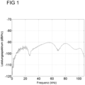
- FIG 1 Figure 12 represents a Fourier spectrum of a single discharge event over a broad frequency range.
- the spectrum shows that at frequencies around 50 to 60 kHz a significant signal gain (20 dB) can be found compared to the frequency (gap) at 25 to 40 kHz. This can be used to set an optimal measurement frequency or the optimal frequency band. The optimization must be adapted to different test situations. Different types of discharge and electrode shapes produce different spectral distributions in the Fourier spectrum.
- figure 2 shows the time-frequency representation of a typical discharge sequence.
- different frequency bands could be chosen to represent the fluctuation over time.
- the cepstral in figure 3 shows the temporal repetition pattern of discharge processes.
- the different types of discharge processes have different characteristics in terms of their repetition structure. There are very even repetitions up to an almost stochastic repetition structure. This structure is characteristic.
- the type of fault, in particular the electrical partial discharge is objectively described with the aid of the signal structure. This evaluation is currently carried out subjectively by experienced testers using the auditory impression (heterodyne method) and its visualization using state-of-the-art methods.
- figure 4 shows the selection of the optimal frequency range for the evaluation of the measurement signal depending on the distance of the ultrasonic microphone from the ultrasonic source.
- the ultrasonic signals 1 to 5 were measured with increasing distance.
- the distances between the ultrasonic microphone and the sound source were as follows: Curve Distance between ultrasonic microphone and sound source 1 5 m 2 10 m 3 40 m 4 100 meters 5 200m
- the distance between the ultrasonic measuring device and the ultrasonic source was the shortest for curve 1 and the greatest for curve 5.
- the frequency-dependent attenuation of the ultrasonic signal with increasing distance can be clearly seen. Higher frequencies are damped significantly more than lower frequencies.
- frequency range A is selected for the evaluation, since the lowest background noise is also to be expected here.
- frequency range B is selected for the evaluation, since the attenuation of the ultrasonic signal is significantly lower here than in range A.
- An evaluation in range A is no longer possible for curves 4 and 5, since for these Frequencies almost no signal can be measured.
- Ultrasonic signals in this frequency range are large in air due to the Distance between the ultrasonic source and the ultrasonic measuring device is almost completely damped. However, an evaluation for the measurement of this distance is still possible for the frequency range C. According to the invention, it is thus possible to detect and evaluate ultrasonic signals from electrical partial discharges even over large distances.
- Figure 5 (A) 1 schematically represents an ultrasonic signal.
- the entire ultrasonic signal is measured over a wide band, ie in the frequency range from 10 kHz to 100 kHz, using the device according to the invention.
- filters can be used to select which frequency range of the entire signal is to be used for further evaluation. Shown are filters from 20 kHz to 40 kHz, from 40 kHz to 60 kHz, from 60 kHz to 80 kHz and from 80 kHz to 100 kHz. These filters are for illustrative purposes only; of course, a different filter width or a different frequency range can also be selected.
- FIG. 5 (B) shows schematically the attenuation of different frequency components of the ultrasonic signal with increasing distance between the ultrasonic source and the ultrasonic microphone. It can be clearly seen that for signal components with higher frequencies, the signal is more strongly attenuated with increasing distance. As the distance increases, it makes sense to evaluate signal components of the measured broadband ultrasonic signal that contain lower frequency ranges.
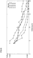
- figure 6 represents the data of the measurement of broadband ultrasonic signals for different distances from the ultrasonic source to the ultrasonic microphone.
- measurements of an ultrasonic signal of an electrical partial discharge were carried out for distances between 4 m and 20 m.
- the method can be used over distances of up to 200 m.
- a broadband ultrasonic signal in the frequency range from 10 kHz to 120 kHz was recorded using a device according to the invention.
- the broadband ultrasonic signal was then further processed with a filter from 20 kHz to 120 kHz and the sound pressure for this distance was determined.
- the measured broadband ultrasonic signal was also evaluated with frequency filters in the range from 80 kHz to 100 kHz, in the range from 60 kHz to 80 kHz, in the range from 40 kHz to 60 kHz and in the range from 20 kHz to 40 kHz and respectively the sound pressure level is calculated.
- the sound pressure levels for the evaluation in the individual frequency ranges depending on the distance are given in the figure 6 shown. It can be clearly seen that with increasing distance, signals in the higher frequency range have a lower sound pressure level than signals in the lower frequency range. This is caused by the increased attenuation with increasing frequency.
Description
Die Erfindung betrifft ein Verfahren zur Detektion und Bewertung von Ultraschallquellen mit einem breitbandigen Ultraschallmikrophon und mobilen Prüfsystem, wobei die Ultraschallquellen akustische Auswirkungen von Störstellen, insbesondere von elektrischen Teilentladungen darstellen, die sich durch Luftschall ausbreiten. Erfindungsgemäß wird ein breitbandiges Ultraschallsignal mindestens einer Ultraschallquelle gemessen und mindestens ein geeignet wählbarer Frequenzbereich des Ultraschallsignals ausgewertet. Die Auswahl des Frequenzbereichs, in dem das Ultraschallsignal ausgewertet wird, erfolgt in Abhängigkeit der verfügbaren Signalstärke, die von der Entfernung zwischen Ultraschallmikrophon und Ultraschallquelle abhängt. Weiterhin betrifft die Erfindung ein Ultraschallmessgerät, insbesondere ein Ultraschallprüfgerät und die Verwendung des erfindungsgemäßen Verfahrens oder des Ultraschallmessgerätes für die Detektion und Bewertung von elektrischen Störstellen.The invention relates to a method for detecting and evaluating ultrasonic sources using a broadband ultrasonic microphone and a mobile test system, the ultrasonic sources representing the acoustic effects of disturbances, in particular electrical partial discharges, which propagate through airborne sound. According to the invention, a broadband ultrasonic signal from at least one ultrasonic source is measured and at least one suitably selectable frequency range of the ultrasonic signal is evaluated. The frequency range in which the ultrasonic signal is evaluated is selected depending on the available signal strength, which depends on the distance between the ultrasonic microphone and the ultrasonic source. Furthermore, the invention relates to an ultrasonic measuring device, in particular an ultrasonic testing device and the use of the method according to the invention or the ultrasonic measuring device for the detection and evaluation of electrical faults.
Die Zuverlässigkeit elektrischer Systeme ist Grundlage für die Versorgung aller Bereich der Gesellschaft mit Energie. Ein wichtiger Teil der industriellen Instandhaltung ist deshalb auf die Sicherheit der Versorgung mit elektrischer Energie und des technischen Betriebs der Anlagen ausgerichtet. Zu den Zielen der vorbeugenden Instandhaltung elektrischer Anlagen gehört das Auffinden und das Bewerten sich entwickelnder Isolationsfehler, um geeignete Maßnahmen einleiten zu können. Typische Probleme treten an vielen Betriebsmitteln der Energieerzeugung, -Übertragung und -verteilung auf, z. B. in (Hochspannungs-) Kabeln, Schaltanlagen, E-Motoren, Generatoren und Transformatoren. Isolationsfehler können zu ernsthaften Folgeschäden und Ausfällen - bis hin zu katastrophalen Situationen - führen.The reliability of electrical systems is the basis for supplying all areas of society with energy. An important part of industrial maintenance is therefore focused on the security of the supply of electrical energy and the technical operation of the systems. One of the goals of preventive maintenance of electrical systems is to find and evaluate developing insulation faults in order to be able to take appropriate measures. Typical problems occur in many power generation, transmission and distribution equipment, e.g. B. in (high-voltage) cables, switchgear, electric motors, generators and transformers. Insulation faults can lead to serious consequential damage and failures - up to and including catastrophic situations.
In Hochspannungsanlagen wie Hochspannungsfreileitungen, Umspanneinrichtungen, Schaltschränken, Trafoanlagen und anderen, gefährden unerwünschte elektrische Teilentladungen die Funktion und Sicherheit.In high-voltage systems such as high-voltage overhead lines, substations, control cabinets, transformer systems and others, undesirable electrical partial discharges endanger function and safety.
Es gibt verschiedene Mess- und Prüftechnologien, solche unerwünschten Teilentladungen nachzuweisen. Neben der Messung der dabei auftretenden elektrischen Felder bzw. induzierten Spannungen werden thermografische Verfahren und auf Ultraviolettstrahlung beruhende Verfahren eingesetzt. Aufgrund der mechanischen Wirkung elektrischer Funken sind auch akustische und Vibrationsmethoden prinzipiell für den Nachweis der Entstehung und der Lokalisierung geeignet.There are various measuring and testing technologies to detect such undesired partial discharges. In addition to measuring the electrical fields or induced voltages that occur, thermographic methods and methods based on ultraviolet radiation are used. Due to the mechanical effect of electric sparks, acoustic and vibration methods are in principle also suitable for proving their origin and localization.
Unterschieden werden dabei innere und äußere Teilentladungen.A distinction is made between inner and outer partial discharges.
Teilentladungen sind gemäß DIN EN 60270 festgelegt als "örtlich beschränkte elektrische Entladung, welche die Isolierung zwischen Leitern nur teilweise überbrückt und welche angrenzend an einen Leiter auftreten kann, aber nicht muss". Die für die Instandhaltung relevanten Teilentladungsphänomene lassen sich in bestimmte Typen eingruppieren wie z.B.:
- Innere Teilentladungen:
- Einschlüsse (Mikanit-Isolierung)
- Treeing (Hochspannungskabel)
- Äußere Teilentladungen:
- Korona (Befestigungselemente, Freileitungen)
- Gleitentladung (Isolatoren)
- Internal partial discharges:
- Inclusions (micanite insulation)
- Treeing (high voltage cable)
- External partial discharges:
- Corona (fasteners, overhead lines)
- creeping discharge (insulators)
Innere Teilentladungen treten auf, wenn durch Inhomogenitäten in Materialien, bei Anliegen elektrischer Felder, hohe Feldstärken erzielt werden können. Aufgrund des Unterschiedes in der Dielektrizitätszahl kann es zu lokalen Spannungsüberschlägen kommen. Diese lokalen Entladungen sind gleichzeitig akustische Quellen. Die Ausbreitungen der Schallwellen erfolgt dann im Medium (Flüssigkeit, Festkörper, umgebende Konstruktion). Diese Phänomene werden durch Verfahren, die auf Vibration und/oder der Ausbreitung von Körperschall beruhen detektiert. Diese Phänomene sind nicht Gegenstand der vorliegenden Erfindung.Internal partial discharges occur when high field strengths can be achieved due to inhomogeneities in materials when electrical fields are present. Due to the difference in the dielectric constant, local voltage flashovers can occur. These local discharges are also acoustic sources. The propagation of the sound waves then takes place in the medium (liquid, solid body, surrounding structure). These phenomena are detected by methods based on vibration and/or the propagation of structure-borne noise. These phenomena are not the subject of the present invention.
Bei luftisolierten elektrischen Betriebsmitteln und daran auftretenden äußeren Teilentladungsphänomenen werden die akustischen Auswirkungen von Entladungen als direkter oder indirekter Schall über die Ausbreitung in Luft weitergeleitet.In the case of air-insulated electrical equipment and the external partial discharge phenomena that occur on it, the acoustic effects of discharges are transmitted as direct or indirect sound via propagation in the air.
Der Nachweis der elektrischen Entladungen erfolgt in der Regel mit im Ultraschallbereich wirksamer Mess- und Prüftechnik. Hierfür stehen analoge und digitale Prüftechniklösungen zur Verfügung.The detection of electrical discharges is usually carried out with measuring and testing technology effective in the ultrasonic range. Analogue and digital test technology solutions are available for this.
Meist werden auf analoger Basis arbeitende Heterodynempfänger eingesetzt, die über ein schmalbandiges Ultraschall-Mikrophon und über eine integrierte Mischer-Frequenz-Technik verfügen, die den in einem engen Frequenzband vorhandenen Ultraschall erfassen und bewerten kann. Physikalisch ist dieser Zugang nicht zwingend. Jedoch ist er relativ einfach und kostengünstig realisierbar. Die elementaren Prozesse bei der elektrischen Entladung laufen sehr schnell ab. Das bedeutet, dass - physikalisch gesehen - ein sehr breites akustisches Spektrum erzeugt wird.In most cases, heterodyne receivers working on an analog basis are used, which have a narrow-band ultrasonic microphone and integrated mixer-frequency technology that can record and evaluate the ultrasound present in a narrow frequency band. Physically, this access is not mandatory. However, it is relatively simple and can be implemented at low cost. The elementary processes involved in electrical discharge take place very quickly. This means that - from a physical point of view - a very broad acoustic spectrum is generated.
Ein typischer Frequenzbereich bei der Erfassung liegt in praktischen Anwendungen um 40 kHz. Die Wahl dieser Frequenz hat pragmatische Gründe. Durch die Verwendung des Ultraschalls spielen Umgebungs- und Störgeräusche im hörbaren Bereich eine geringere Rolle als bei der Erfassung von Signalen im hörbaren Bereich. Weiterhin zeichnet sich Ultraschall dadurch aus, dass seine Ausbreitungsrichtung gut nachverfolgt werden kann und dadurch eine Quellenortung leichter als bei tieferen Frequenzen möglich ist. Es ist zum einen preiswerte Sensorik (Ultraschall-Abstandswarnung bei Fahrzeugen) vorhanden und zum anderen ist die Reichweite von Ultraschall bei 40 kHz noch groß genug, um praxisrelevante Anwendungsszenarien zu bedienen. Die Nachweistechnik wird dabei meist als tragbares Handprüfgerät ausgeführt. Zur Unterstützung der Lokalisierung der Quelle und zur physikalischen Verstärkung des Signals werden geeignete Hohlspiegel eingesetzt.A typical detection frequency range is around 40 kHz in practical applications. The choice of this frequency has pragmatic reasons. By using ultrasound, ambient noise and background noise in the audible range play a less important role than when detecting signals in the audible range. Furthermore, ultrasound is characterized by the fact that its direction of propagation can be easily tracked, making it easier to locate the source than with lower frequencies. On the one hand, inexpensive sensors (ultrasonic distance warning for vehicles) are available and, on the other hand, the range of ultrasound at 40 kHz is still large enough to serve practical application scenarios. The detection technology is usually carried out as a portable hand-held test device. Appropriate concave mirrors are used to help localize the source and to physically amplify the signal.
Die Einführung digitaler breitbandiger Prüftechnik ermöglicht die Nutzung des gesamten akustisch auftretenden Frequenzbereichs. Die Bewertung kann anhand geeigneter Anzeige und Aufzeichnung des Ultraschallsignals (Amplitudenverlauf, Spektrogramme, Pegeldarstellungen) vorgenommen werden. Eine digitale Nachbildung der analogen Schmalbandverfahren ist dabei ebenfalls möglich. Ein wichtiges Element der Realisierung auf Basis breitbandiger Ultraschalltechnologie ist die komplette Digitalisierung der gesamten Signalkette. Damit ist auch die Integration und Optimierung von Algorithmen der Signalverarbeitung möglich.The introduction of digital broadband testing technology enables the use of the entire acoustically occurring frequency range. The assessment can be made using a suitable display and recording of the ultrasonic signal (amplitude curve, spectrograms, level displays). A digital simulation of the analog narrowband method is also possible. An important element of the implementation based on broadband ultrasonic technology is the complete digitization of the entire signal chain. This also enables the integration and optimization of signal processing algorithms.
Die Ausbreitung von Schall in Luft unterliegt bekanntermaßen einer frequenzabhängigen Dämpfung. Als Alltagserfahrung ist gegenwärtig, dass der Blitze begleitende Donner z. T. nur bei niederen Frequenzen hörbar ist. Die bei der Entladung auftretenden höheren Frequenzen werden über größere Entfernungen von der Luft absorbiert. Dieser Effekt ist auch bei Entfernung wirksam, wie sie bei der Überprüfung elektrischer Entladungen üblich sind (einige Meter bis 10 m).The propagation of sound in air is known to be subject to frequency dependent attenuation. As everyday experience it is present that the lightning accompanying thunder e.g. T. is only audible at low frequencies. The higher frequencies occurring during discharge are absorbed by the air over greater distances. This effect is also effective at distances common when checking electrical discharges (a few meters to 10 m).
Die Dämpfung in Luft hängt von der Entfernung, der Temperatur und der Feuchtigkeit ab. Der Druckeinfluss kann vernachlässigt werden. Die Ausbreitung von Schall im Freien wird in der DIN ISO 9613 (Dämpfung des Schalls bei der Ausbreitung im Freien) beschrieben. Dort sind die diesbezüglichen Dämpfungskoeffizienten in nachvollziehbarer Form angegeben. Eine exakte analytische Beschreibung ist aufgrund der Vielzahl von Parametern während einer Prüfung von Entladungsvorgängen nicht möglich. Dies ist aber auch aufgrund der bei der Prüfung erreichbaren und geforderten Genauigkeit nicht erforderlich. Eine Prognose aufgrund der Prüfsituation ohne weitere Maßnahmen würde auf eine grobe Schätzung hinauslaufen.Attenuation in air depends on distance, temperature and humidity. The influence of pressure can be neglected. The propagation of sound outdoors is described in DIN ISO 9613 (damping of sound propagating outdoors). The relevant damping coefficients are given there in a comprehensible form. An exact analytical description is not possible due to the large number of parameters when testing discharge processes. However, this is also not necessary due to the accuracy that can be achieved and is required during the test. A forecast based on the test situation without further measures would amount to a rough estimate.
Bei den Verfahren, die den Stand der Technik widerspiegeln, hängt die Bewertung von Ultraschallquellen mehr oder weniger zufällig von der Prüfentfernung ab. Die eingestellte Messfrequenz (z.B. 40 kHz) ist nur zufällig geeignet. Wenn man die Entfernungen vergrößert, verringern sich die Amplituden der höheren Frequenzen und die Charakteristik des Ultraschallsignals ist unter Umständen in dem verwendeten Messbereich nicht mehr detektierbar. Die Verfahren aus dem Stand der Technik sind daher nicht geeignet, elektrische Störungen sowohl aus kleineren wie auch aus größeren Entfernungen zu untersuchen und die Intensitäten zu vergleichen. Die digitalen breitbandigen Ultraschalldaten enthalten immer für jede Messentfernung ein von der Entfernungsdämpfung beeinflusstes Spektrum.With the methods reflecting the state of the art, the evaluation of ultrasonic sources depends more or less randomly on the test distance. The set measuring frequency (e.g. 40 kHz) is only suitable by chance. If the distances are increased, the amplitudes of the higher frequencies decrease and the characteristics of the ultrasonic signal may no longer be detectable in the measuring range used. The methods from the prior art are therefore not suitable for examining electrical interference from both smaller and larger distances and for comparing the intensities. The digital broadband ultrasound data always contain a spectrum influenced by the distance attenuation for each measurement distance.
Darüber hinaus erfolgt keine automatische Bewertung der Mess- und Prüfdaten durch die bisher bekannten Lösungen. Die Bewertung muss der Nutzer/Prüfer anhand seines Erfahrungswissens durch Betrachtung der Messwerte auf einem Bildschirm oder Datenschriebs in einem Protokoll vornehmen oder anhand eines Höreindrucks. Insbesondere die Bewertung anhand des Höreindrucks ist sehr subjektiv geprägt und hängt stark von der Erfahrung des Prüfers ab.In addition, the previously known solutions do not automatically evaluate the measurement and test data. The user/tester must carry out the assessment based on his/her experience by looking at the measured values on a screen or data record in a log, or based on an auditory impression. In particular, the evaluation based on the auditory impression is very subjective and depends heavily on the experience of the examiner.
Weiterhin können durch die Nutzung der analogen Schmalbandfrequenztechnik nicht alle physikalisch möglichen Situationen erfasst werden, die auftreten können.Furthermore, not all physically possible situations that can occur can be detected through the use of analog narrowband frequency technology.
Die verfügbare digitale Prüftechnik dagegen, die Frequenzen bis etwa 100 kHz Bandbreite bewertet, kann nur Rohdaten liefern. Eine integrierte oder nachgeschaltete Bewertung ist nicht verfügbar.On the other hand, the available digital testing technology, which evaluates frequencies up to a bandwidth of around 100 kHz, can only supply raw data. An integrated or downstream assessment is not available.
Die physikalisch begründeten Spezifika elektrischer Entladungen werden in keiner der bekannten Lösungen berücksichtigt. Elektrische Entladungen sind ein transientes Phänomen, auf dessen Erfassung die Messtechnik und Software nicht optimal ausgelegt ist. Eine Unterscheidung von unterschiedlichen Entladungsmustern ist bisher nicht möglich und nicht vorgesehen.The physically based specifics of electrical discharges are not taken into account in any of the known solutions. Electrical discharges are a transient phenomenon The measurement technology and software are not optimally designed to record this. A distinction between different discharge patterns has not been possible up to now and is not intended.
Die
Die
Die
Die
Der vorliegenden Erfindung liegt daher die Aufgabe zu Grunde, die akustische Auswirkung einer Teilentladung, die sich durch Luftschall ausbreitet, unter Berücksichtigung der Auswirkungen des Abstands des verwendeten Ultraschallmikrophons zur Ultraschallquelle zu detektieren und zu bewerten, beziehungsweise zu klassifizieren.The present invention is therefore based on the object of detecting and evaluating, or classifying, the acoustic effect of a partial discharge that propagates through airborne noise, taking into account the effects of the distance between the ultrasonic microphone used and the ultrasonic source.
Hierfür stellt die Erfindung ein Verfahren zur Detektion und Bewertung von Ultraschallquellen mit einem breitbandigen Ultraschallmikrophon zur Verfügung, wobei die Ultraschallquellen akustische Auswirkungen einer elektrischen Teilentladung darstellen, die sich durch Luftschall ausbreiten, dadurch gekennzeichnet, dass
- ein breitbandiges Ultraschallsignal mindestens einer Ultraschallquelle gemessen wird; mindestens ein Frequenzbereich des Ultraschallsignals ausgewertet wird;
- und dass die Auswahl des Frequenzbereichs, in dem das Ultraschallsignal ausgewertet wird in Abhängigkeit von der Entfernung zwischen Ultraschallmikrophon und Ultraschallquelle erfolgt.
- a broadband ultrasound signal of at least one ultrasound source is measured; at least one frequency range of the ultrasonic signal is evaluated;
- and that the frequency range in which the ultrasonic signal is evaluated is selected as a function of the distance between the ultrasonic microphone and the ultrasonic source.
Darüber hinaus stellt die Erfindung ein Ultraschallmessgerät zur Detektion von breitbandigem Ultraschall zur Verfügung, aufweisend
- ein breitbandiges Ultraschallmikrophon;
- Messelektronik, aufweisend eine Bibliothek von Cepstra für bekannte elektrische Teilentladungen;
- Nutzeroberfläche;
- optional einen Entfernungsmesser;
- wobei das Ultraschallmessgerät dazu eingerichtet ist, die akustischen Auswirkungen einer elektrischen Teilentladung, die sich durch Luftultraschall ausbreitet zu detektieren und zu bewerten;
- und wobei das Ultraschallmessgerät dazu eingerichtet ist einen auszuwertenden Frequenzbereich in Abhängigkeit einer Entfernung des Ultraschallmikrophons zu einer vermessenen Ultraschallquelle auszuwählen.
- a broadband ultrasonic microphone;
- Measuring electronics, having a library from Cepstra for known electrical partial discharges;
- user interface;
- optionally a range finder;
- wherein the ultrasonic measuring device is set up to detect and evaluate the acoustic effects of an electrical partial discharge that propagates through airborne ultrasound;
- and wherein the ultrasonic measuring device is set up to select a frequency range to be evaluated depending on a distance of the ultrasonic microphone from a measured ultrasonic source.
Weiterhin wird die Verwendung des erfindungsgemäßen Verfahrens oder des erfindungsgemäßen Ultraschallmessgerätes für die Detektion und Bewertung von elektrischen Störstellen, insbesondere von elektrischen Teilentladungen beschrieben.Furthermore, the use of the method according to the invention or the ultrasonic measuring device according to the invention for the detection and evaluation of electrical faults, in particular electrical partial discharges, is described.
Merkmale, die im Folgenden für das erfindungsgemäße Verfahren beschrieben werden, gelten genauso für das erfindungsgemäße Ultraschallmessgerät und umgekehrt.Features that are described below for the method according to the invention also apply to the ultrasonic measuring device according to the invention and vice versa.
Ultraschallquellen gemäß der vorliegenden Erfindung sind, wie bereits eingangs beschrieben, Quellen von denen verursacht durch elektrische Teilentladungen Luftultraschall ausgesendet wird. Besonders bevorzugt sind die Ultraschallquellen Störstellen, bevorzugt elektrische Störstellen, an denen elektrische Teilentladungen auftreten.Ultrasound sources according to the present invention are, as already described at the outset, sources from which airborne ultrasound is emitted as a result of electrical partial discharges. The ultrasonic sources are particularly preferably imperfections, preferably electrical imperfections, at which electrical partial discharges occur.
Gemäß dem erfindungsgemäßen Verfahren wird ein breitbandiges Ultraschallsignal mindestens einer Ultraschallquelle gemessen. In einer bevorzugten Ausführungsform der vorliegenden Erfindung wird ein Ultraschallsignal genau einer Ultraschallquelle gemessen. Breitbandig bedeutet in diesem Zusammenhang, dass bevorzugt Frequenzen im Bereich von 10 kHz bis 100 kHz, insbesondere im Bereich von 20 kHz bis 100 kHz, erfasst werden. Das Ultraschallsignal wird bevorzugt mit einer Abtastrate fs > 200 kHz abgetastet.According to the method according to the invention, a broadband ultrasound signal is measured from at least one ultrasound source. In a preferred embodiment of the present invention, an ultrasonic signal is measured precisely from an ultrasonic source. In this context, broadband means that frequencies in the range from 10 kHz to 100 kHz, in particular in the range from 20 kHz to 100 kHz, are preferably detected. The ultrasonic signal is preferably sampled at a sampling rate f s >200 kHz.
Erfindungsgemäß wird mindestens ein Frequenzbereich des Ultraschallsignals ausgewertet, um das Ultraschallsignal zu bewerten.According to the invention, at least one frequency range of the ultrasonic signal is evaluated in order to evaluate the ultrasonic signal.
In einer Ausführungsform der vorliegenden Erfindung wird die Entfernung zwischen Ultraschallquelle und Ultraschallmikrophon gemessen. Anhand der gemessenen Entfernung wird ein Frequenzbereich des Ultraschallsignals für die Auswertung ausgewählt. Mit zunehmender Entfernung von der Ultraschallquelle wird Ultraschall höherer Frequenzen stärker gedämpft als das Ultraschallsignal niedrigerer Frequenzen. Mit zunehmender Entfernung verschiebt sich der Frequenzbereich, der ausgewertet wird, daher zu kleineren Frequenzen. Der Frequenzbereich für die Auswertung hängt dabei von der Schallleistung der Quelle und von der Empfindlichkeit der Messkette und von deren Dynamikbereich ab. Für Entfernungen zwischen Ultraschallmikrophon und Schallquelle von mehreren zehn Metern hat sich gezeigt, dass der Frequenzbereich für die Auswertung um 40 kHz zentriert liegt. Für Entfernungen bis 10 m zeigt sich, dass ein Frequenzbereich um 100 kHz am günstigsten ist. Für Bereiche um 100 m und darüber wird ein Frequenzbereich um die 10 kHz ausgewertet. Damit ist vorteilhafterweise mit der vorliegenden Erfindung ein großer Entfernungsbereich zwischen Ultraschallmikrophon und Ultraschallquelle erfassbar. Teilentladungen als akustische Quellen, die als Störquellen wirken, können somit in einer Entfernung zum Ultraschallmikrophon unterhalb von 10 m bis zu einer Entfernung von 200 m und darüber detektiert und bewertet werden.In one embodiment of the present invention, the distance between the ultrasound source and the ultrasound microphone is measured. Based on the measured distance, a frequency range of the ultrasonic signal is selected for the evaluation. With increasing distance from the ultrasound source, higher frequency ultrasound is attenuated more than the lower frequency ultrasound signal. As the distance increases, the frequency range that is evaluated shifts to lower frequencies. The frequency range for the evaluation depends on the sound power of the source and on the sensitivity of the measuring chain and its dynamic range. For distances between the ultrasonic microphone and the sound source of several tens of meters, it has been shown that the frequency range for the evaluation is centered around 40 kHz. For Distances of up to 10 m show that a frequency range of around 100 kHz is best. For ranges of 100 m and above, a frequency range of around 10 kHz is evaluated. A large distance range between the ultrasonic microphone and the ultrasonic source can thus advantageously be detected with the present invention. Partial discharges as acoustic sources that act as sources of interference can thus be detected and evaluated at a distance from the ultrasonic microphone of less than 10 m up to a distance of 200 m and more.
In einer bevorzugten Ausführungsform der vorliegenden Erfindung, wird bei einer Entfernung zwischen Ultraschallmikrophon und Ultraschallquelle bis 10 m ein Frequenzbereich des Ultraschallsignals ausgewertet, der zwischen 60 kHz und 100 kHz, bevorzugt zwischen 70 kHz und 100 kHz, besonders bevorzugt zwischen 80 kHz und 100 kHz liegt.In a preferred embodiment of the present invention, at a distance between the ultrasonic microphone and the ultrasonic source of up to 10 m, a frequency range of the ultrasonic signal is evaluated which is between 60 kHz and 100 kHz, preferably between 70 kHz and 100 kHz, particularly preferably between 80 kHz and 100 kHz .
In einer bevorzugten Ausführungsform der vorliegenden Erfindung wird bei einer Entfernung zwischen Ultraschallmikrophon und Ultraschallquelle zwischen 10 m und 100 m ein Frequenzbereich des Ultraschallsignals ausgewertet, der zwischen 20 kHz und 60 kHz, bevorzugt zwischen 30 kHz und 60 kHz, besonders bevorzugt zwischen 40 kHz und 60 kHz liegt.In a preferred embodiment of the present invention, at a distance between the ultrasonic microphone and the ultrasonic source of between 10 m and 100 m, a frequency range of the ultrasonic signal is evaluated which is between 20 kHz and 60 kHz, preferably between 30 kHz and 60 kHz, particularly preferably between 40 kHz and 60 kHz lies.
In einer bevorzugten Ausführungsform der vorliegenden Erfindung wird bei einer Entfernung zwischen Ultraschallmikrophon und Ultraschallquelle über 100 m ein Frequenzbereich des Ultraschallsignals ausgewertet, der zwischen 10 kHz und 40 kHz, bevorzugt zwischen 10 kHz und 30 kHz, besonders bevorzugt zwischen 10 kHz und 20 kHz liegt.In a preferred embodiment of the present invention, a frequency range of the ultrasonic signal between 10 kHz and 40 kHz, preferably between 10 kHz and 30 kHz, particularly preferably between 10 kHz and 20 kHz, is evaluated at a distance between the ultrasonic microphone and the ultrasonic source of more than 100 m.
In einer Ausführungsform der Erfindung werden Ultraschallquellen bis zu einer Entfernung von 200 m zwischen Ultraschallquelle und Ultraschallmikrophon detektiert und bewertet.In one embodiment of the invention, ultrasonic sources are detected and evaluated up to a distance of 200 m between the ultrasonic source and the ultrasonic microphone.
In einer Ausführungsform der Erfindung hat der mindestens eine Frequenzbereich, der für die Auswertung genutzt wird, typischerweise eine Bandbreite von 10 bis 20 kHz.In one embodiment of the invention, the at least one frequency range that is used for the evaluation typically has a bandwidth of 10 to 20 kHz.
Die elektrischen Störstellen, insbesondere elektrische Teilentladungen, werden ab einer Entfernung gemessen, bei der die Elemente der Messkette aus Messelektronik und Ultraschallmikrophon sensitiv genug sind und sich dadurch das durch die Entladung verursachte Signal aus dem Störgeräusch (Umgebungsgeräusche, elektronisches Rauschen) heraushebt. In einer Ausführungsform liegt der Schwellenwert für das elektronische Rauschen bei etwa 20 dB (auf p0 = 20 µPa bezogen). Signale aus determinierten Quellen lassen sich bei einer Pegeldifferenz von ca. 5 dB zum Rauschen sicher erfassen.The electrical disturbances, in particular electrical partial discharges, are measured from a distance at which the elements of the measurement chain made up of measurement electronics and ultrasonic microphone are sensitive enough and the discharge caused by the discharge caused signal from the background noise (ambient noise, electronic noise). In one embodiment, the electronic noise threshold is about 20 dB (relative to p 0 =20 µPa). Signals from determined sources can be reliably detected with a level difference of approx. 5 dB to the noise.
Die frequenzabhängige Dämpfung des Ultraschallsignals hängt von vielen Faktoren ab. Neben der reinen Dämpfung, die physikalisch gut zu beschreiben wäre, spielt auch die Messumgebung wie Untergrund, Reflexionsumgebungen, Vegetation aber auch Feuchtigkeit eine Rolle. Die Entfernungsberücksichtigung erfolgt deshalb bevorzugt aus dem breitbandigen Spektrum selbst. Die Auswahl des Frequenzbereichs, in dem das Ultraschallsignal ausgewertet wird, erfolgt dann in Abhängigkeit der verfügbaren Signalstärke, die wiederum von der Entfernung zwischen Ultraschallmikrophon und Ultraschallquelle abhängt. Dabei wird der Frequenzbereich mit der höchsten Signalstärke ausgewertet. Die Entfernung zwischen Ultraschallquelle und Ultraschallmikrophon muss dem Prüfer daher nicht zwingend zur Verfügung stehen.The frequency-dependent attenuation of the ultrasonic signal depends on many factors. In addition to the pure attenuation, which can be well described physically, the measuring environment such as the subsoil, reflection surroundings, vegetation and also humidity also play a role. The distance is therefore preferably taken into account from the broadband spectrum itself. The frequency range in which the ultrasonic signal is evaluated is then selected as a function of the available signal strength, which in turn depends on the distance between the ultrasonic microphone and the ultrasonic source. The frequency range with the highest signal strength is evaluated. The distance between the ultrasonic source and the ultrasonic microphone therefore does not necessarily have to be available to the tester.
Vorteilhafterweise steht einem Nutzer das gesamte breitbandig gemessene Ultraschallsignal zur Verfügung, so dass es möglich ist, auch mehr als einen Frequenzbereich auszuwerten, bzw. verschiedene Frequenzfilter auf das gemessene Signal anzuwenden.Advantageously, the entire broadband measured ultrasonic signal is available to a user, so that it is also possible to evaluate more than one frequency range, or to use different frequency filters on the measured signal.
Bevorzugt wird das detektierte Zeitsignal in Echtzeit verarbeitet. In einer Ausführungsform der vorliegenden Erfindung wird das gesamte Zeitsignal aufgezeichnet und gespeichert. In diesem Fall stehen die Daten vorteilhafterweise auch für eine Datenverarbeitung zu einem späteren Zeitpunkt noch zur Verfügung.The detected time signal is preferably processed in real time. In one embodiment of the present invention, the entire time signal is recorded and stored. In this case, the data are advantageously still available for data processing at a later point in time.
Im Rahmen der vorliegenden Erfindung wird die Varianz und damit die Fluktuation der Zeit-Frequenz-Eigenschaften des Signals als Muster bezeichnet. Das Muster wird maßgeblich durch die zeitliche Variation der Signalamplitude bestimmt. Die Zeit-Signalform ist eine Mischung aus stochastischen und systematischen Abfolgen akustischer Signale. Darin ist die eigentliche Information über Störstellen, insbesondere über elektrische Teilentladungen, enthalten. Die Elementarereignisse sind dabei über einen breiten Frequenzbereich verteilt. Als Elementarereignisse werden im Rahmen der vorliegenden Erfindung Teilentladungen bezeichnet, die eine akustische Auswirkung haben, die sich durch Luftultraschall ausbreitet.In the context of the present invention, the variance and thus the fluctuation of the time-frequency properties of the signal is referred to as a pattern. The pattern is largely determined by the temporal variation of the signal amplitude. The time waveform is a mixture of stochastic and systematic sequences of acoustic signals. This contains the actual information about faults, in particular about electrical partial discharges. The elementary events are distributed over a wide frequency range. In the context of the present invention, elementary events are partial discharges that have an acoustic effect that propagates through airborne ultrasound.
Das Zeitsignal kann durch bekannte Mittel, wie beispielsweise einer Fourier-Transformation in den Frequenzraum überführt werden. Die Fouriertransformation kann sowohl an den hochfrequenten Ultraschalldaten als auch an den hörbar gemachten Daten mit reduzierter Datenrate ausgeführt werden. Eine günstige Darstellung im Zeit-Frequenz-Raum wird als Spektrogramm bezeichnet.The time signal can be converted into the frequency space by known means, such as a Fourier transformation. The Fourier transformation can be performed both on the high-frequency ultrasound data and on the data made audible with a reduced data rate. A convenient representation in the time-frequency space is called a spectrogram.
Das hochfrequente, gemessene Ultraschall-Zeitsignal ist die Grundlage für alle weiteren Berechnungen gemäß der vorliegenden Erfindung. Dieses hochfrequente, gemessene Ultraschallsignal an sich, ist für die direkte Nutzung in der Prüfung nicht geeignet, jedoch hat sich gezeigt, dass bei einer geeigneten Verarbeitung des Hochfrequenz-Ultraschallsignals dieses für die Nutzung in der Prüfung zugänglich gemacht werden kann.The high-frequency, measured ultrasonic time signal is the basis for all further calculations according to the present invention. This high-frequency, measured ultrasonic signal itself is not suitable for direct use in the test, but it has been shown that with suitable processing of the high-frequency ultrasonic signal, it can be made accessible for use in the test.
In einer Ausführungsform der vorliegenden Erfindung wird aus dem für die Auswertung ausgewählten Frequenzbereich des Messsignals ein geeignet gefiltertes neues Zeitsignal generiert.In one embodiment of the present invention, a suitably filtered new time signal is generated from the frequency range of the measurement signal selected for the evaluation.
Das neue Zeitsignal kann durch eines der im Folgenden genannten Verfahren erzeugt werden. Allen Verfahren gemein ist, dass die für das Ultraschallsignal charakteristische Modulation erhalten bleibt. Sämtliche Verfahren werden bevorzugt in Echtzeit angewendet.
- a. Breitbandige Berechnung und Darstellung der Spektren
- b. Heterodynsignal: Eine Ausführungsform hat eine Bandbreite von +/-2 kHz um die Trägerfrequenz. Typische Anwendungen verwenden
eine Trägerfrequenz von 40 kHz aufgrund der verfügbaren einfachen Sensoren. Aufgrund der breitbandigen digitalen Messung kann die Trägerfrequenz und die Bandbreite beliebig variiert werden. Eine gleichzeitige Berechnung vieler Frequenzbänder in Heterodyn-Technik ist möglich. Dies kann auch für die Audioausgabe im Hörbereich genutzt werden. Das Signal hat eine geringere Zeitauflösung als das originale Hochfrequenzsignal. Die Heterodyn-Technik an sich ist dem Fachmann zwar bekannt, jedoch ist die Verwendung gemäß dem vorliegenden Verfahren als Filterbank dem Fachmann so nicht geläufig und in analoger Form auch nicht realisierbar. Dies wird erst ermöglicht, indem gemäß dem vorliegenden Verfahren, die Heterodyn-Technik in Verbindung mit einem breitbandig detektierten Ultraschallsignal genutzt wird. - c. Vocodersignal: Mit dieser Datenkompression wird das Ultraschallsignal hörbar gemacht. Die zeitliche Dynamik bleibt auch im Höreindruck erhalten. Da dieser Signaltyp eine Frequenzkomprimierung des gesamten Ultraschallbereichs abbildet, können auch für das Vocodersignal Bandpässe berechnet werden, die jeweils einem Ultraschall-Frequenzband zugeordnet werden können. Wenn das Ultraschall-Signal in 1, 2, 4, 6 oder 12 Bänder zerlegt wird, betrifft dies in der skalierten Form auch das Vocodersignal mit der analogen Anzahl von Bändern. Die Anwendung des Vocoderverfahrens ist dem Fachmann bekannt.
- d. Bandpass gefilterte Hochfrequenz-Signale: Eine Filterbank trennt das Signal im Zeitbereich in unterschiedliche Zeitsignale auf. Aufgrund der breitbandigen akustischen Signale ist die Information über die Fluktuation in allen Frequenzbändern gleich (bei möglicherweise unterschiedlicher Amplitude). Zur Bewertung für qualitative Zwecke ist ein Frequenzband, in dem eine genügend große Amplitude vorhanden ist, ausreichend. Für jedes Frequenzband kann ein repräsentativer Amplitudenwert verwendet werden. Geeignet ist eine gemittelte Amplitude. Ein Nachteil dieser Verfahrensvariante ist, dass hierbei die Möglichkeit spektraler Berechnungen verloren geht.
- a. Broadband calculation and display of the spectra
- b. Heterodyne Signal: One embodiment has a bandwidth of +/-2 kHz around the carrier frequency. Typical applications use a carrier frequency of 40kHz due to the simple sensors available. Due to the broadband digital measurement, the carrier frequency and the bandwidth can be varied as desired. A simultaneous calculation of many frequency bands in heterodyne technology is possible. This can also be used for audio output in the listening area. The signal has a lower time resolution than the original high-frequency signal. Although the heterodyne technique is known per se to the person skilled in the art, the use according to the present method as a filter bank is not familiar to the person skilled in the art and also cannot be implemented in an analogous form. This is only made possible by according to the present method, the heterodyne technique is used in connection with a broadband detected ultrasonic signal.
- c. Vocoder signal: This data compression makes the ultrasonic signal audible. The temporal dynamics are also retained in the auditory impression. Since this signal type represents a frequency compression of the entire ultrasonic range, bandpasses can also be calculated for the vocoder signal, which can each be assigned to an ultrasonic frequency band. If the ultrasonic signal is divided into 1, 2, 4, 6 or 12 bands, this also affects the vocoder signal with the analog number of bands in the scaled form. The use of the vocoder method is known to those skilled in the art.
- i.e. Bandpass filtered high-frequency signals: A filter bank separates the signal in the time domain into different time signals. Due to the broadband acoustic signals, the information about the fluctuation is the same in all frequency bands (with possibly different amplitudes). A frequency band in which there is a sufficiently large amplitude is sufficient for evaluation for qualitative purposes. A representative amplitude value can be used for each frequency band. An average amplitude is suitable. A disadvantage of this variant of the method is that the possibility of spectral calculations is lost.
In einer weiteren Ausführungsform der Erfindung werden von dem mit dem Ultraschallmikrophon detektierten Zeitsignal die Einhüllenden der zeitlichen Fluktuationen berechnet. Dies kann durch eine Hilbert-Transformation des Zeitsignals erreicht werden. Diese Vorgehensweise ist insbesondere dann vorteilhaft, wenn auf die spektrale Information verzichtet werden kann. Da die Einhüllenden ebenfalls Zeitfunktionen sind, können diese die (globalen) Amplitudenfluktuationen des detektierten Ultraschallsignals widerspiegeln und für die bereits beschriebenen Berechnungsverfahren a. bis d. verwendet werden. In einer Ausführungsform der vorliegenden Erfindung werden die Einhüllenden der zeitlichen Fluktuationen des detektierten Ultraschallsignals berechnet und anschließend als ein neues Zeitsignal verwendet.In a further embodiment of the invention, the envelopes of the temporal fluctuations are calculated from the time signal detected with the ultrasonic microphone. This can be achieved by Hilbert transforming the time signal. This procedure is particularly advantageous when the spectral information can be dispensed with. Since the envelopes are also time functions, they can reflect the (global) amplitude fluctuations of the detected ultrasonic signal and for the calculation methods already described a. until d. be used. In an embodiment of the present invention, the envelopes of the temporal fluctuations of the detected ultrasonic signal are calculated and then used as a new time signal.
Zur Objektivierung der Bewertung wird ein weiterer Signalverarbeitungsschritt, bevorzugt in Echtzeit, eingefügt. In Zeitsignalen mit stochastischem Charakter lassen sich versteckte und sich wiederholende Strukturen überraschend gut mit der Operation Cepstrum aus dem Bereich der Fourieranalyse sichtbar machen. Die Signale werden dabei auf eine inverse Frequenz bezogen. Diese ist dann formal wieder eine Zeit und kann als ein Maß für den Wiederholabstand verstanden werden. In einer Ausführungsform der vorliegenden Erfindung wird für das Ultraschallsignal ein Cepstrum berechnet.A further signal processing step, preferably in real time, is added to objectify the assessment. In time signals with a stochastic character, hidden and make repeating structures visible surprisingly well with the operation cepstrum from the field of Fourier analysis. The signals are related to an inverse frequency. Formally, this is again a time and can be understood as a measure of the repetition distance. In one embodiment of the present invention, a cepstrum is calculated for the ultrasonic signal.
Das Cepstrum kann als geeignete Grundlage für eine visuelle Unterscheidung (Betrachtung durch Prüfer) oder als Eingang für einen weiteren Signalverarbeitungsschritt zur automatischen Bewertung dienen. Bei der visuellen Bewertung durch einen Prüfer kann die Bewertung einmal auf der Grundlage der Erfahrung des Prüfers geschehen. Möglich ist aber auch, dass das berechnete Cepstrum entweder durch einen Prüfer oder aber automatisch mit Methoden der Mustererkennung mit bereits bekannten Cepstra-Mustern, verglichen wird, wobei die bekannten Cepstra die Ultraschallsignale von genau definierten Arten von elektrischen Teilentladungen widerspiegeln. Basis hierfür ist eine umfangreiche experimentelle Datenbasis.The cepstrum can serve as a suitable basis for visual discrimination (observation by examiners) or as an input to a further signal processing step for automatic assessment. In the case of the visual evaluation by an examiner, the evaluation can be made once based on the experience of the examiner. However, it is also possible for the calculated cepstrum to be compared either by a tester or automatically using pattern recognition methods with already known cepstra patterns, with the known cepstra reflecting the ultrasonic signals of precisely defined types of electrical partial discharges. The basis for this is an extensive experimental database.
Die unterschiedlichen Arten von Entladungsvorgängen haben unterschiedliche Ausprägungen hinsichtlich ihrer Wiederholungsstruktur. Es gibt sehr gleichmäßige Wiederholungen bis hin zu einer fast stochastischen Wiederholungsstruktur. Diese Struktur ist charakteristisch für unterschiedliche Varianten elektrischer Teilentladungen. Mit dem vorliegenden Verfahren kann daher aus der Signalstruktur, der Typ der Störstelle objektiv beschrieben werden, ohne dass, wie mit den Verfahren aus dem Stand der Technik üblich, auf die subjektive Bewertung von erfahrenen Prüfern mittels des Höreindruckes (Heterodynverfahren) und der Visualisierung des (hörbaren) Audiosignals zurückgegriffen werden muss. Das vorliegende Verfahren stellt damit vorteilhafterweise ein Prüfverfahren für Störstellen, insbesondere für elektrische Teilentladungen an Störstellen zur Verfügung, welches eine objektive Prüfung unabhängig vom jeweiligen Prüfer ermöglicht.The different types of discharge processes have different characteristics in terms of their repetition structure. There are very even repetitions up to an almost stochastic repetition structure. This structure is characteristic of different variants of electrical partial discharges. With the present method, the type of disturbance can therefore be described objectively from the signal structure without, as is usual with the methods from the prior art, relying on the subjective evaluation of experienced testers using the auditory impression (heterodyne method) and the visualization of the ( audible) audio signal must be used. The present method thus advantageously provides a testing method for faults, in particular for electrical partial discharges at faults, which enables objective testing independently of the respective tester.
In einer weiteren Ausführungsform der vorliegenden Erfindung kann die Berechnung des Cepstrum auch im Nachhinein mit Hilfe der gespeicherten Messdaten erfolgen.In a further embodiment of the present invention, the cepstrum can also be calculated retrospectively with the aid of the stored measurement data.
Es hat sich gezeigt, dass man bei größeren Entfernungen die Mess- oder Bewertungsfrequenz hin zu deutlich kleineren Frequenzen verschieben kann. Die Bewertung kann korrekt erfolgen, da das zeitliche Bewertungsmuster, das mit dem Cepstrum erfasst werden kann, erhalten bleibt.It has been shown that the measurement or evaluation frequency can be shifted to significantly lower frequencies at greater distances. The evaluation can be done correctly because the temporal evaluation pattern that can be captured with the cepstrum is preserved.
Im Prinzip kann man bei sehr großen Entfernungen auch die hörbaren Frequenzen verwenden, wobei allerdings störender hörbarer Schall aus der Bewertung eliminiert werden muss. Damit können Entfernungen bis zu einigen hundert Metern erreicht werden. Dies ist mit den bisher bekannten Verfahren nicht möglich. Die bei größeren Entfernungen zwischen Ultraschallquelle und Ultraschallmikrophon schlechter werdende Richtwirkung des Schalls lässt sich durch den Einsatz eines Hohlspiegels teilweise kompensieren. In einer Ausführungsform des erfindungsgemäßen Verfahrens wird die Richtwirkung des Ultraschalls daher mit einem Hohlspiegel teilweise korrigiert.In principle, the audible frequencies can also be used for very large distances, although disturbing audible noise must be eliminated from the evaluation. This enables distances of up to a few hundred meters to be reached. This is not possible with the previously known methods. The directional effect of the sound, which deteriorates as the distance between the ultrasound source and the ultrasound microphone increases, can be partially compensated for by using a concave mirror. In one embodiment of the method according to the invention, the directivity of the ultrasound is therefore partially corrected with a concave mirror.
Die Auswahl eines geeigneten Frequenzbandes erleichtert die Prüfung für den Nutzer. Die Auswahl (Heterodyn, Bandfilter, oder Breitband) kann digital erfolgen. Bei der Verwendung des Breitbandsignals und Speicherung des Hochfrequenz-Signals können alle Situationen (Offline) nachberechnet werden.Selecting a suitable frequency band makes testing easier for the user. The selection (heterodyne, bandpass filter, or broadband) can be done digitally. When using the broadband signal and storing the high-frequency signal, all situations (offline) can be recalculated.
Die Erfindung stellt weiterhin ein Ultraschallmessgerät zur Detektion von breitbandigem Ultraschall zur Verfügung. Das Ultraschallmessgerät ist bevorzugt ein Ultraschallprüfgerät, welches entsprechend zu Prüfzwecken zum Einsatz kommen kann.The invention also provides an ultrasonic measuring device for detecting broadband ultrasound. The ultrasonic measuring device is preferably an ultrasonic testing device, which can be used accordingly for testing purposes.
Gemäß der vorliegenden Erfindung wird digitale Messtechnik eingesetzt. Die Ultraschallmesstechnik muss hierfür mit einem breitbandigen Ultraschallmikrophon ausgestattet sein. Bevorzugt ist dies ein Ultraschallmikrophon, das Frequenzen von 10 bis 100 kHz erfassen kann. In einer weiteren Ausführungsform der Erfindung ist dies ein Mikrophon, welches auch für hohe Frequenzen (bis ca. 100 kHz) ausgelegt ist und mit geeigneten Frequenzfiltern in der digitalen Messkette betrieben wird. Geeignete Frequenzfilter sind beispielsweise 1/3-Oktavfilter oder weitere Unterteilungen (1/6- oder 1/12-Oktav-Filter) sowie frei wählbare digitale Filter.According to the present invention, digital measurement technology is used. For this purpose, the ultrasonic measurement technology must be equipped with a broadband ultrasonic microphone. This is preferably an ultrasonic microphone that can detect frequencies from 10 to 100 kHz. In a further embodiment of the invention, this is a microphone which is also designed for high frequencies (up to approx. 100 kHz) and is operated with suitable frequency filters in the digital measurement chain. Suitable frequency filters are, for example, 1/3 octave filters or other subdivisions (1/6 or 1/12 octave filters) and freely selectable digital filters.
Das Ultraschallmikrophon ist mit einer geeigneten Messelektronik in einer Messkette verbunden. Das Prüfgerät integriert eine digital gespeicherte Bibliothek von Cepstra, die die Ultraschallsignale von genau definierten Arten von elektrischen Teilentladungen widerspiegeln.The ultrasonic microphone is connected to suitable measurement electronics in a measurement chain. The tester integrates a digitally stored library from Cepstra that reflects the ultrasonic signals of precisely defined types of partial electrical discharges.
Weiterhin weist das Ultraschallmessgerät eine Nutzeroberfläche auf, mit deren Hilfe ein Nutzer navigieren kann und bestimmte Verfahrensschritte auswählen kann. Derart ist es möglich eine Messung auszulösen oder die Auswertung der Messdaten zu beeinflussen. Das Messergebnis kann vorteilhafterweise ebenfalls auf der Nutzeroberfläche dargestellt werden. In einer bevorzugten Ausführungsform ist die Nutzeroberfläche eine grafische Nutzeroberfläche mit Touchbedienung.Furthermore, the ultrasonic measuring device has a user interface that a user can use to navigate and select specific method steps. In this way it is possible to trigger a measurement or to influence the evaluation of the measurement data. The measurement result can advantageously also be displayed on the user interface. In a preferred embodiment, the user interface is a graphical user interface with touch operation.
Optional weist das Ultraschallmessgerät einen Entfernungsmesser auf. In einer bevorzugten Ausführungsform weist das Ultraschallmessgerät einen Entfernungsmesser auf. Die gemessene Entfernung kann dann für die Auswahl des Frequenzbereiches genutzt werden, der ausgewertet werden soll. Wie bereits beschrieben ist eine Entfernungsmessung jedoch nicht zwingend notwendig, da die Information über den Einfluss der Entfernung bereits in den breitbandigen Ultraschalldaten enthalten ist. Die Integration der Möglichkeit einer direkten Entfernungsmessung kann jedoch zur Bestätigung der Bewertung eingesetzt werden oder um die Vergleichbarkeit unterschiedlicher Messpositionen zu gewährleisten.Optionally, the ultrasonic measuring device has a range finder. In a preferred embodiment, the ultrasonic measuring device has a range finder. The measured distance can then be used to select the frequency range to be evaluated. As already described, however, a distance measurement is not absolutely necessary, since the information about the influence of the distance is already contained in the broadband ultrasound data. However, the integration of the possibility of a direct distance measurement can be used to confirm the evaluation or to ensure the comparability of different measurement positions.
In einer Ausführungsform der Erfindung weist das Ultraschallmessgerät weiterhin einen Hohlspiegel auf. Dies erweist sich insbesondere dann als vorteilhaft, wenn sich das Ultraschallmessgerät in größerer Entfernung von der Quelle des Ultraschallsignals befindet oder wenn sehr kleine Schallpegel vorliegen. Durch Einsatz des Hohlspiegels lässt sich die schlechter werdende Richtwirkung des Ultraschalls kompensieren und das Signal-zu-Rausch Verhältnis wird verbessert. Die Signalverbesserung liegt bei 6 dB. Damit können Schallquellen gleicher Leistung etwa doppelt so weit gefunden und bewertet werden. Dabei wirkt sich die Kombination der Verwendung von Hohlspiegeln und eines Frequenzbandes mit niedrigeren Ultraschallfrequenzen günstig auf die Prüfbarkeit von Teilentladungen bei größeren Entfernungen aus.In one embodiment of the invention, the ultrasonic measuring device also has a concave mirror. This proves to be particularly advantageous when the ultrasonic measuring device is located at a greater distance from the source of the ultrasonic signal or when the sound levels are very low. By using the concave mirror, the deteriorating directivity of the ultrasound can be compensated and the signal-to-noise ratio is improved. The signal improvement is 6 dB. This means that sound sources of the same power can be found and evaluated twice as far. The combination of the use of concave mirrors and a frequency band with lower ultrasonic frequencies has a favorable effect on the testability of partial discharges at greater distances.
Das Ultraschallmessgerät, insbesondere Ultraschallprüfgerät ist besonders bevorzugt als Handgerät ausgebildet. Somit sind eine einfache Handhabung, sowie ein unkomplizierter Transport des Gerätes möglich. Das Ultraschallmessgerät kann damit flexibel als mobiles Prüfsystem eingesetzt und angewendet werden.The ultrasonic measuring device, in particular ultrasonic testing device, is particularly preferably designed as a hand-held device. Thus, easy handling and uncomplicated transport of the device are possible. The ultrasonic measuring device can thus be used and applied flexibly as a mobile testing system.
Das erfindungsgemäße Verfahren und das erfindungsgemäße Ultraschallmessgerät werden bevorzugt für die Detektion und Bewertung von Störstellen, insbesondere von elektrischen Teilentladungen, verwendet. Die Störstellen sind bevorzugt elektrische Störstellen an denen Teilentladungen auftreten, die Ultraschallsignale verursachen, die sich durch Luftultraschall fortpflanzen. Das Verfahren und das Ultraschallmessgerät sind erfindungsgemäß dafür ausgelegt, solche Störstellen bis zu einer Entfernung zwischen Ultraschallmikrophon und Ultraschallquelle von etwa 200 m zu detektieren und zu bewerten.The method according to the invention and the ultrasonic measuring device according to the invention are preferably used for the detection and evaluation of faults, in particular electrical partial discharges. The imperfections are preferably electrical imperfections at which partial discharges occur, which cause ultrasonic signals that propagate through airborne ultrasound. According to the invention, the method and the ultrasonic measuring device are designed to detect and evaluate such imperfections up to a distance of approximately 200 m between the ultrasonic microphone and the ultrasonic source.
Im Folgenden wird die Erfindung anhand von 6 Figuren und 1 Ausführungsbeispiel näher erläutert.
Figur 1- stellt ein Fourierspektrum eines Einzelereignisses einer Entladung dar;
- Figur 2
- stellt eine Zeit-Frequenz-Darstellung einer Entladungssequenz dar;
Figur 3- stellt ein Cepstrum dar;
Figur 4- stellt die Anpassung des Frequenzabschnitts, der ausgewertet wird an die entfernungsabhängige Dämpfung des Ultraschallsignals dar;
Figur 5- (A) und (B) stellen schematisch ein Ultraschallsignal dar und die Dämpfung des Signals mit der Entfernung von der Ultraschallquelle;
- Figur 6
- stellt die Dämpfung von Ultraschallsignalen in verschiedenen Frequenzbereichen mit der Entfernung von der Ultraschallquelle dar.
- figure 1
- Figure 14 represents a Fourier spectrum of a single event of a discharge;
- figure 2
- Figure 12 illustrates a time-frequency representation of a discharge sequence;
- figure 3
- represents a cepstrum;
- figure 4
- represents the adjustment of the frequency section that is evaluated to the distance-dependent attenuation of the ultrasonic signal;
- figure 5
- (A) and (B) schematically depict an ultrasonic signal and the attenuation of the signal with distance from the ultrasonic source;
- figure 6
- represents the attenuation of ultrasonic signals in different frequency ranges with distance from the ultrasonic source.
Das Cepstrum in
Dabei war die Entfernung des Ultraschallmessegerätes zur Ultraschallquelle für die Messkurve 1 am geringsten und für die Messkurve 5 am größten. Deutlich ist die frequenzabhängige Dämpfung des Ultraschallsignals mit zunehmender Entfernung zu erkennen. Größere Frequenzen werden deutlich stärker gedämpft als kleinere Frequenzen. Für die Messung der Kurve 1 mit dem geringsten Abstand zwischen Ultraschallmessgerät und Ultraschallquelle wird für die Auswertung der Frequenzbereich A gewählt, da hier auch mit dem geringsten Störschall zu rechnen ist. Für die Kurven 2 und 3 wird hingegen der Frequenzbereich B für die Auswertung gewählt, da hier die Dämpfung des Ultraschallsignals wesentlich geringer ist als im Bereich A. Für die Kurven 4 und 5 ist eine Auswertung im Bereich A gar nicht mehr möglich, da für diese Frequenzen so gut wie kein Signal mehr gemessen werden kann. Ultraschallsignale in diesem Frequenzbereich werden in der Luft aufgrund der großen Entfernung zwischen Ultraschallquelle und Ultraschallmessgerät nahezu komplett gedämpft. Eine Auswertung ist für die Messung dieser Entfernung jedoch noch für den Frequenzbereich C möglich. Erfindungsgemäß wird damit eine Detektion und Bewertung von Ultraschalsignalen von elektrischen Teilentladungen auch auf große Distanzen ermöglicht.The distance between the ultrasonic measuring device and the ultrasonic source was the shortest for
Beispielhaft wurden Messungen eines Ultraschallsignals einer elektrischen Teilentladung für Entfernungen zwischen 4 m und 20 m durchgeführt. Wie bereits beschrieben ist das Verfahren bis auf Entfernungen von bis zu 200 m anwendbar. Für jede Entfernung wurde mit einer erfindungsgemäßen Vorrichtung ein breitbandiges Ultraschallsignal im Frequenzbereich von 10 kHz bis 120 kHz aufgenommen. Das breitbandige Ultraschallsignal wurde anschließend mit einem Filter von 20 kHz bis 120 kHz weiterverarbeitet und der Schalldruck für diese Entfernung bestimmt. Auf das gemessene breitbandige Ultraschallsignal wurde ebenfalls mit Frequenzfiltern im Bereich von 80 kHz bis 100 kHz, im Bereich von 60 kHz bis 80 kHz, im Bereich von 40 kHz bis 60 kHz und im Bereich von 20 kHz bis 40 kHz ausgewertet und jeweils der Schalldruckpegel berechnet. Die Schalldruckpegel für die Auswertung in den einzelnen Frequenzbereichen in Abhängigkeit von der Entfernung sind in der
Claims (15)
- Method for detecting and assessing ultrasonic sources with a broadband ultrasonic microphone, wherein the ultrasonic sources constitute acoustic effects of an electrical partial discharge which propagate through airborne sound, characterized in thata broadband ultrasonic signal from at least one ultrasonic source is measured;at least one frequency range of the ultrasonic signal is evaluated;and in that the frequency range in which the ultrasonic signal is evaluated is selected on the basis of the distance between the ultrasonic microphone and the ultrasonic source.
- Method according to Claim 1, characterized in that a broadband ultrasonic signal with frequencies of 10 kHz to 100 kHz is measured.
- Method according to one of the preceding claims, characterized in that, for distances between the ultrasonic microphone and the ultrasonic source of up to 10 m, a frequency range of the ultrasonic signal which is between 60 kHz and 100 kHz, preferably between 70 kHz and 100 kHz, particularly preferably between 80 kHz and 100 kHz, is evaluated.
- Method according to one of the preceding claims, characterized in that, for distances between the ultrasonic microphone and the ultrasonic source of between 10 m and 100 m, a frequency range of the ultrasonic signal which is between 20 kHz and 60 kHz, preferably between 30 kHz and 60 kHz, particularly preferably between 40 kHz and 60 kHz, is evaluated.
- Method according to one of the preceding claims, characterized in that, for distances between the ultrasonic microphone and the ultrasonic source of more than 100 m, a frequency range of the ultrasonic signal which is between 10 kHz and 40 kHz, preferably between 10 kHz and 30 kHz, particularly preferably between 10 kHz and 20 kHz, is evaluated.
- Method according to one of the preceding claims, characterized in that the distance is considered from the broadband spectrum itself.
- Method according to one of the preceding claims, characterized in that the distance between the ultrasonic source and the ultrasonic microphone is measured.
- Method according to one of the preceding claims, characterized in that a cepstrum is calculated for the ultrasonic signal.
- Method according to one of the preceding claims, characterized in that the ultrasonic signal is assessed by comparing the calculated cepstrum with cepstra which are available for ultrasonic signals of precisely defined types of electrical partial discharges.
- Method according to one of the preceding claims, characterized in that the ultrasonic signal is assessed in real time.
- Method according to one of the preceding claims, characterized in that ultrasonic sources up to a distance of 200 m are detected and assessed.
- Ultrasonic measurement device for detecting broadband ultrasound, configured to carry out a method according to one of Claims 1 to 11, having• a broadband ultrasonic microphone;• measurement electronics having a library of cepstra for known electrical partial discharges;• a user interface;• optionally a distance meter;wherein the ultrasonic measurement device is configured to detect and assess the acoustic effects of an electrical partial discharge which propagates through air ultrasound;characterized in thatthe ultrasonic measurement device is configured to select a frequency range to be evaluated on the basis of a distance between the ultrasonic microphone and a measured ultrasonic source.
- Ultrasonic measurement device according to Claim 12, characterized in that the ultrasonic measurement device also has a concave mirror.
- Ultrasonic measurement device according to either of Claims 12 and 13, characterized in that the ultrasonic measurement device is in the form of a handheld device.
- Use of the method according to one of Claims 1 to 11 or of the ultrasonic measurement device according to one of Claims 12 to 14 for detecting and assessing electrical faults.
Applications Claiming Priority (1)
| Application Number | Priority Date | Filing Date | Title |
|---|---|---|---|
| DE102020116622.2A DE102020116622A1 (en) | 2020-06-24 | 2020-06-24 | Process for broadband ultrasonic detection of electrical discharges |
Publications (2)
| Publication Number | Publication Date |
|---|---|
| EP3929600A1 EP3929600A1 (en) | 2021-12-29 |
| EP3929600B1 true EP3929600B1 (en) | 2023-06-07 |
Family
ID=76601043
Family Applications (1)
| Application Number | Title | Priority Date | Filing Date |
|---|---|---|---|
| EP21181381.1A Active EP3929600B1 (en) | 2020-06-24 | 2021-06-24 | Method for broadband ultrasonic detection of electrical discharges |
Country Status (3)
| Country | Link |
|---|---|
| EP (1) | EP3929600B1 (en) |
| DE (1) | DE102020116622A1 (en) |
| FI (1) | FI3929600T3 (en) |
Families Citing this family (1)
| Publication number | Priority date | Publication date | Assignee | Title |
|---|---|---|---|---|
| CN114325270B (en) * | 2021-12-30 | 2023-07-04 | 广东电网有限责任公司江门供电局 | Switch cabinet partial discharge monitoring method and device |
Family Cites Families (7)
| Publication number | Priority date | Publication date | Assignee | Title |
|---|---|---|---|---|
| JPS59171540A (en) * | 1983-03-18 | 1984-09-28 | 富士通株式会社 | Measurement utilizing spectrum shape |
| CN103038599B (en) | 2010-04-16 | 2016-03-30 | U·E·系统公司 | Onboard ultrasound ripple frequency spectrum and Computer image genration |
| DE102011101044A1 (en) | 2011-05-09 | 2012-11-15 | CAE Engineering und Service GmbH | Apparatus and method for determining a sound emission level |
| KR101318926B1 (en) * | 2012-06-28 | 2013-10-17 | 정의종 | System for detecting defect of complex acoustic emission sensor module using based on magnetic power |
| WO2015100577A1 (en) | 2013-12-31 | 2015-07-09 | Siemens Aktiengesellschaft | Devices and methods for arc fault detection |
| EP2975397B1 (en) | 2014-07-18 | 2020-01-15 | Siemens Aktiengesellschaft | High frequency acoustic spectrum imaging method and corresponding device |
| CN109490730A (en) * | 2018-12-19 | 2019-03-19 | 国网北京市电力公司 | Cable discharge detection method, device, storage medium and processor |
-
2020
- 2020-06-24 DE DE102020116622.2A patent/DE102020116622A1/en not_active Ceased
-
2021
- 2021-06-24 EP EP21181381.1A patent/EP3929600B1/en active Active
- 2021-06-24 FI FIEP21181381.1T patent/FI3929600T3/en active
Also Published As
| Publication number | Publication date |
|---|---|
| EP3929600A1 (en) | 2021-12-29 |
| FI3929600T3 (en) | 2023-09-04 |
| DE102020116622A1 (en) | 2021-12-30 |
Similar Documents
| Publication | Publication Date | Title |
|---|---|---|
| EP3513154B1 (en) | Method and device for determining and/or monitoring the breakdown voltage of a transformer oil | |
| EP1537390B1 (en) | Method for detecting oscillations of the shafting of an electric machine | |
| EP2204660B1 (en) | Method and device for determining partial discharges from an electric component | |
| DE3990151C1 (en) | Audio signal processor input-output characteristic parameter measurer | |
| EP2405279A2 (en) | Method and device for locating cable errors | |
| DE60025466T2 (en) | METHOD AND MEASURING APPARATUS FOR INVESTIGATING A TERRITORY FOR THE PRESENCE / REDUCTION OF A SPECIFIC GEOPHYSICAL PROPERTY | |
| DE102005025449A1 (en) | Method and device for measuring a dielectric response of an electrical insulation system | |
| DE102016003133B4 (en) | Method for automatically determining an individual function of a DPOAE level map of a human or animal hearing | |
| EP0938831A1 (en) | Hearing-adapted quality assessment of audio signals | |
| EP3929600B1 (en) | Method for broadband ultrasonic detection of electrical discharges | |
| DE102011087915A1 (en) | Method for monitoring the patient load in a magnetic resonance device | |
| EP2441274B1 (en) | Method for determining an averaged frequency dependent transfer function for a disturbed lti-system, evaluation unit and computer program | |
| DE102014005698A1 (en) | Method and device for spatially resolved diagnosis | |
| EP2487495A1 (en) | Method and device for measuring a dielectric response from an electrical insulation system | |
| DE102005033491A1 (en) | Detecting precise location of leak at pipeline or ground surface, uses acoustic receiver to record and compares series of noise-related measurements at various positions | |
| DE1541755C3 (en) | Arrangement for locating electrical insulation faults | |
| DE102017208996A1 (en) | Method for mass spectrometric analysis of a gas and mass spectrometer | |
| DE102014007761A1 (en) | Method for determining the value of a vibroacoustic variable | |
| EP3736580B1 (en) | Detection of a dc component in an inductive device | |
| WO2021151683A1 (en) | Sound-based current measuring | |
| DE10315372B4 (en) | Method and device for providing a measurement signal and device for detecting an electromagnetic interference | |
| DE102019104742A1 (en) | Device and method for the automatic detection of a partial discharge | |
| EP1520170B1 (en) | Method and device for testing a hollow body | |
| DE19623871A1 (en) | Statistical phase analysis of oto-acoustic emissions method, for acoustic screening | |
| DE19626329C2 (en) | Procedure for the analysis of sound events |
Legal Events
| Date | Code | Title | Description |
|---|---|---|---|
| PUAI | Public reference made under article 153(3) epc to a published international application that has entered the european phase |
Free format text: ORIGINAL CODE: 0009012 |
|
| STAA | Information on the status of an ep patent application or granted ep patent |
Free format text: STATUS: THE APPLICATION HAS BEEN PUBLISHED |
|
| AK | Designated contracting states |
Kind code of ref document: A1 Designated state(s): AL AT BE BG CH CY CZ DE DK EE ES FI FR GB GR HR HU IE IS IT LI LT LU LV MC MK MT NL NO PL PT RO RS SE SI SK SM TR |
|
| B565 | Issuance of search results under rule 164(2) epc |
Effective date: 20211117 |
|
| STAA | Information on the status of an ep patent application or granted ep patent |
Free format text: STATUS: REQUEST FOR EXAMINATION WAS MADE |
|
| 17P | Request for examination filed |
Effective date: 20220505 |
|
| RBV | Designated contracting states (corrected) |
Designated state(s): AL AT BE BG CH CY CZ DE DK EE ES FI FR GB GR HR HU IE IS IT LI LT LU LV MC MK MT NL NO PL PT RO RS SE SI SK SM TR |
|
| GRAP | Despatch of communication of intention to grant a patent |
Free format text: ORIGINAL CODE: EPIDOSNIGR1 |
|
| STAA | Information on the status of an ep patent application or granted ep patent |
Free format text: STATUS: GRANT OF PATENT IS INTENDED |
|
| RIC1 | Information provided on ipc code assigned before grant |
Ipc: G01R 31/12 20200101AFI20220711BHEP |
|
| INTG | Intention to grant announced |
Effective date: 20220729 |
|
| GRAJ | Information related to disapproval of communication of intention to grant by the applicant or resumption of examination proceedings by the epo deleted |
Free format text: ORIGINAL CODE: EPIDOSDIGR1 |
|
| STAA | Information on the status of an ep patent application or granted ep patent |
Free format text: STATUS: REQUEST FOR EXAMINATION WAS MADE |
|
| GRAP | Despatch of communication of intention to grant a patent |
Free format text: ORIGINAL CODE: EPIDOSNIGR1 |
|
| STAA | Information on the status of an ep patent application or granted ep patent |
Free format text: STATUS: GRANT OF PATENT IS INTENDED |
|
| INTC | Intention to grant announced (deleted) | ||
| INTG | Intention to grant announced |
Effective date: 20221214 |
|
| GRAS | Grant fee paid |
Free format text: ORIGINAL CODE: EPIDOSNIGR3 |
|
| GRAA | (expected) grant |
Free format text: ORIGINAL CODE: 0009210 |
|
| STAA | Information on the status of an ep patent application or granted ep patent |
Free format text: STATUS: THE PATENT HAS BEEN GRANTED |
|
| AK | Designated contracting states |
Kind code of ref document: B1 Designated state(s): AL AT BE BG CH CY CZ DE DK EE ES FI FR GB GR HR HU IE IS IT LI LT LU LV MC MK MT NL NO PL PT RO RS SE SI SK SM TR |
|
| REG | Reference to a national code |
Ref country code: GB Ref legal event code: FG4D Free format text: NOT ENGLISH |
|
| REG | Reference to a national code |
Ref country code: CH Ref legal event code: EP Ref country code: AT Ref legal event code: REF Ref document number: 1576696 Country of ref document: AT Kind code of ref document: T Effective date: 20230615 Ref country code: DE Ref legal event code: R096 Ref document number: 502021000782 Country of ref document: DE |
|
| P01 | Opt-out of the competence of the unified patent court (upc) registered |
Effective date: 20230517 |
|
| REG | Reference to a national code |
Ref country code: NL Ref legal event code: FP |
|
| REG | Reference to a national code |
Ref country code: LT Ref legal event code: MG9D |
|
| PG25 | Lapsed in a contracting state [announced via postgrant information from national office to epo] |
Ref country code: SE Free format text: LAPSE BECAUSE OF FAILURE TO SUBMIT A TRANSLATION OF THE DESCRIPTION OR TO PAY THE FEE WITHIN THE PRESCRIBED TIME-LIMIT Effective date: 20230607 Ref country code: NO Free format text: LAPSE BECAUSE OF FAILURE TO SUBMIT A TRANSLATION OF THE DESCRIPTION OR TO PAY THE FEE WITHIN THE PRESCRIBED TIME-LIMIT Effective date: 20230907 Ref country code: ES Free format text: LAPSE BECAUSE OF FAILURE TO SUBMIT A TRANSLATION OF THE DESCRIPTION OR TO PAY THE FEE WITHIN THE PRESCRIBED TIME-LIMIT Effective date: 20230607 |
|
| PGFP | Annual fee paid to national office [announced via postgrant information from national office to epo] |
Ref country code: IT Payment date: 20230630 Year of fee payment: 3 Ref country code: FI Payment date: 20230901 Year of fee payment: 3 |
|
| PG25 | Lapsed in a contracting state [announced via postgrant information from national office to epo] |
Ref country code: RS Free format text: LAPSE BECAUSE OF FAILURE TO SUBMIT A TRANSLATION OF THE DESCRIPTION OR TO PAY THE FEE WITHIN THE PRESCRIBED TIME-LIMIT Effective date: 20230607 Ref country code: LV Free format text: LAPSE BECAUSE OF FAILURE TO SUBMIT A TRANSLATION OF THE DESCRIPTION OR TO PAY THE FEE WITHIN THE PRESCRIBED TIME-LIMIT Effective date: 20230607 Ref country code: LT Free format text: LAPSE BECAUSE OF FAILURE TO SUBMIT A TRANSLATION OF THE DESCRIPTION OR TO PAY THE FEE WITHIN THE PRESCRIBED TIME-LIMIT Effective date: 20230607 Ref country code: HR Free format text: LAPSE BECAUSE OF FAILURE TO SUBMIT A TRANSLATION OF THE DESCRIPTION OR TO PAY THE FEE WITHIN THE PRESCRIBED TIME-LIMIT Effective date: 20230607 Ref country code: GR Free format text: LAPSE BECAUSE OF FAILURE TO SUBMIT A TRANSLATION OF THE DESCRIPTION OR TO PAY THE FEE WITHIN THE PRESCRIBED TIME-LIMIT Effective date: 20230908 |
|
| PGFP | Annual fee paid to national office [announced via postgrant information from national office to epo] |
Ref country code: DE Payment date: 20230830 Year of fee payment: 3 Ref country code: BE Payment date: 20230817 Year of fee payment: 3 |
|
| PG25 | Lapsed in a contracting state [announced via postgrant information from national office to epo] |
Ref country code: SK Free format text: LAPSE BECAUSE OF FAILURE TO SUBMIT A TRANSLATION OF THE DESCRIPTION OR TO PAY THE FEE WITHIN THE PRESCRIBED TIME-LIMIT Effective date: 20230607 |
|
| PG25 | Lapsed in a contracting state [announced via postgrant information from national office to epo] |
Ref country code: IS Free format text: LAPSE BECAUSE OF FAILURE TO SUBMIT A TRANSLATION OF THE DESCRIPTION OR TO PAY THE FEE WITHIN THE PRESCRIBED TIME-LIMIT Effective date: 20231007 |
|
| PG25 | Lapsed in a contracting state [announced via postgrant information from national office to epo] |
Ref country code: SM Free format text: LAPSE BECAUSE OF FAILURE TO SUBMIT A TRANSLATION OF THE DESCRIPTION OR TO PAY THE FEE WITHIN THE PRESCRIBED TIME-LIMIT Effective date: 20230607 Ref country code: SK Free format text: LAPSE BECAUSE OF FAILURE TO SUBMIT A TRANSLATION OF THE DESCRIPTION OR TO PAY THE FEE WITHIN THE PRESCRIBED TIME-LIMIT Effective date: 20230607 Ref country code: RO Free format text: LAPSE BECAUSE OF FAILURE TO SUBMIT A TRANSLATION OF THE DESCRIPTION OR TO PAY THE FEE WITHIN THE PRESCRIBED TIME-LIMIT Effective date: 20230607 Ref country code: PT Free format text: LAPSE BECAUSE OF FAILURE TO SUBMIT A TRANSLATION OF THE DESCRIPTION OR TO PAY THE FEE WITHIN THE PRESCRIBED TIME-LIMIT Effective date: 20231009 Ref country code: IS Free format text: LAPSE BECAUSE OF FAILURE TO SUBMIT A TRANSLATION OF THE DESCRIPTION OR TO PAY THE FEE WITHIN THE PRESCRIBED TIME-LIMIT Effective date: 20231007 Ref country code: EE Free format text: LAPSE BECAUSE OF FAILURE TO SUBMIT A TRANSLATION OF THE DESCRIPTION OR TO PAY THE FEE WITHIN THE PRESCRIBED TIME-LIMIT Effective date: 20230607 Ref country code: CZ Free format text: LAPSE BECAUSE OF FAILURE TO SUBMIT A TRANSLATION OF THE DESCRIPTION OR TO PAY THE FEE WITHIN THE PRESCRIBED TIME-LIMIT Effective date: 20230607 |
|
| PGFP | Annual fee paid to national office [announced via postgrant information from national office to epo] |
Ref country code: FR Payment date: 20231018 Year of fee payment: 3 |
|
| PG25 | Lapsed in a contracting state [announced via postgrant information from national office to epo] |
Ref country code: PL Free format text: LAPSE BECAUSE OF FAILURE TO SUBMIT A TRANSLATION OF THE DESCRIPTION OR TO PAY THE FEE WITHIN THE PRESCRIBED TIME-LIMIT Effective date: 20230607 |
|
| PG25 | Lapsed in a contracting state [announced via postgrant information from national office to epo] |
Ref country code: LU Free format text: LAPSE BECAUSE OF NON-PAYMENT OF DUE FEES Effective date: 20230624 |
|
| PG25 | Lapsed in a contracting state [announced via postgrant information from national office to epo] |
Ref country code: MC Free format text: LAPSE BECAUSE OF FAILURE TO SUBMIT A TRANSLATION OF THE DESCRIPTION OR TO PAY THE FEE WITHIN THE PRESCRIBED TIME-LIMIT Effective date: 20230607 |
|
| REG | Reference to a national code |
Ref country code: IE Ref legal event code: MM4A |
|
| PG25 | Lapsed in a contracting state [announced via postgrant information from national office to epo] |
Ref country code: MC Free format text: LAPSE BECAUSE OF FAILURE TO SUBMIT A TRANSLATION OF THE DESCRIPTION OR TO PAY THE FEE WITHIN THE PRESCRIBED TIME-LIMIT Effective date: 20230607 Ref country code: LU Free format text: LAPSE BECAUSE OF NON-PAYMENT OF DUE FEES Effective date: 20230624 |
|
| PLBE | No opposition filed within time limit |
Free format text: ORIGINAL CODE: 0009261 |
|
| STAA | Information on the status of an ep patent application or granted ep patent |
Free format text: STATUS: NO OPPOSITION FILED WITHIN TIME LIMIT |
|
| PG25 | Lapsed in a contracting state [announced via postgrant information from national office to epo] |
Ref country code: IE Free format text: LAPSE BECAUSE OF NON-PAYMENT OF DUE FEES Effective date: 20230624 |