EP3929539A1 - Scanning unit and rotary encoder with same - Google Patents
Scanning unit and rotary encoder with same Download PDFInfo
- Publication number
- EP3929539A1 EP3929539A1 EP20181310.2A EP20181310A EP3929539A1 EP 3929539 A1 EP3929539 A1 EP 3929539A1 EP 20181310 A EP20181310 A EP 20181310A EP 3929539 A1 EP3929539 A1 EP 3929539A1
- Authority
- EP
- European Patent Office
- Prior art keywords
- metal frame
- scanning unit
- substrate
- axis
- circuit board
- Prior art date
- Legal status (The legal status is an assumption and is not a legal conclusion. Google has not performed a legal analysis and makes no representation as to the accuracy of the status listed.)
- Granted
Links
- 229910052751 metal Inorganic materials 0.000 claims abstract description 75
- 239000002184 metal Substances 0.000 claims abstract description 75
- 239000000758 substrate Substances 0.000 claims abstract description 39
- 238000007373 indentation Methods 0.000 claims abstract description 12
- 230000002093 peripheral effect Effects 0.000 abstract 1
- 239000004020 conductor Substances 0.000 description 22
- 230000005284 excitation Effects 0.000 description 14
- 230000001419 dependent effect Effects 0.000 description 4
- 238000000034 method Methods 0.000 description 3
- 238000005520 cutting process Methods 0.000 description 2
- 238000013461 design Methods 0.000 description 2
- 230000005672 electromagnetic field Effects 0.000 description 2
- 238000011156 evaluation Methods 0.000 description 2
- 230000001939 inductive effect Effects 0.000 description 2
- 230000000737 periodic effect Effects 0.000 description 2
- 229910000838 Al alloy Inorganic materials 0.000 description 1
- RYGMFSIKBFXOCR-UHFFFAOYSA-N Copper Chemical compound [Cu] RYGMFSIKBFXOCR-UHFFFAOYSA-N 0.000 description 1
- 239000000853 adhesive Substances 0.000 description 1
- 230000001070 adhesive effect Effects 0.000 description 1
- 230000015572 biosynthetic process Effects 0.000 description 1
- 229910052802 copper Inorganic materials 0.000 description 1
- 239000010949 copper Substances 0.000 description 1
- 230000008878 coupling Effects 0.000 description 1
- 238000010168 coupling process Methods 0.000 description 1
- 238000005859 coupling reaction Methods 0.000 description 1
- 238000011161 development Methods 0.000 description 1
- 230000018109 developmental process Effects 0.000 description 1
- 230000000694 effects Effects 0.000 description 1
- 239000003822 epoxy resin Substances 0.000 description 1
- 230000006698 induction Effects 0.000 description 1
- 239000000463 material Substances 0.000 description 1
- 230000013011 mating Effects 0.000 description 1
- 238000005259 measurement Methods 0.000 description 1
- 230000003287 optical effect Effects 0.000 description 1
- 229920000647 polyepoxide Polymers 0.000 description 1
- 238000004080 punching Methods 0.000 description 1
- XLYOFNOQVPJJNP-UHFFFAOYSA-N water Substances O XLYOFNOQVPJJNP-UHFFFAOYSA-N 0.000 description 1
Images
Classifications
-
- G—PHYSICS
- G01—MEASURING; TESTING
- G01D—MEASURING NOT SPECIALLY ADAPTED FOR A SPECIFIC VARIABLE; ARRANGEMENTS FOR MEASURING TWO OR MORE VARIABLES NOT COVERED IN A SINGLE OTHER SUBCLASS; TARIFF METERING APPARATUS; MEASURING OR TESTING NOT OTHERWISE PROVIDED FOR
- G01D5/00—Mechanical means for transferring the output of a sensing member; Means for converting the output of a sensing member to another variable where the form or nature of the sensing member does not constrain the means for converting; Transducers not specially adapted for a specific variable
- G01D5/12—Mechanical means for transferring the output of a sensing member; Means for converting the output of a sensing member to another variable where the form or nature of the sensing member does not constrain the means for converting; Transducers not specially adapted for a specific variable using electric or magnetic means
- G01D5/244—Mechanical means for transferring the output of a sensing member; Means for converting the output of a sensing member to another variable where the form or nature of the sensing member does not constrain the means for converting; Transducers not specially adapted for a specific variable using electric or magnetic means influencing characteristics of pulses or pulse trains; generating pulses or pulse trains
- G01D5/24428—Error prevention
- G01D5/24433—Error prevention by mechanical means
-
- G—PHYSICS
- G01—MEASURING; TESTING
- G01D—MEASURING NOT SPECIALLY ADAPTED FOR A SPECIFIC VARIABLE; ARRANGEMENTS FOR MEASURING TWO OR MORE VARIABLES NOT COVERED IN A SINGLE OTHER SUBCLASS; TARIFF METERING APPARATUS; MEASURING OR TESTING NOT OTHERWISE PROVIDED FOR
- G01D5/00—Mechanical means for transferring the output of a sensing member; Means for converting the output of a sensing member to another variable where the form or nature of the sensing member does not constrain the means for converting; Transducers not specially adapted for a specific variable
- G01D5/12—Mechanical means for transferring the output of a sensing member; Means for converting the output of a sensing member to another variable where the form or nature of the sensing member does not constrain the means for converting; Transducers not specially adapted for a specific variable using electric or magnetic means
- G01D5/14—Mechanical means for transferring the output of a sensing member; Means for converting the output of a sensing member to another variable where the form or nature of the sensing member does not constrain the means for converting; Transducers not specially adapted for a specific variable using electric or magnetic means influencing the magnitude of a current or voltage
- G01D5/20—Mechanical means for transferring the output of a sensing member; Means for converting the output of a sensing member to another variable where the form or nature of the sensing member does not constrain the means for converting; Transducers not specially adapted for a specific variable using electric or magnetic means influencing the magnitude of a current or voltage by varying inductance, e.g. by a movable armature
-
- G—PHYSICS
- G01—MEASURING; TESTING
- G01D—MEASURING NOT SPECIALLY ADAPTED FOR A SPECIFIC VARIABLE; ARRANGEMENTS FOR MEASURING TWO OR MORE VARIABLES NOT COVERED IN A SINGLE OTHER SUBCLASS; TARIFF METERING APPARATUS; MEASURING OR TESTING NOT OTHERWISE PROVIDED FOR
- G01D5/00—Mechanical means for transferring the output of a sensing member; Means for converting the output of a sensing member to another variable where the form or nature of the sensing member does not constrain the means for converting; Transducers not specially adapted for a specific variable
- G01D5/12—Mechanical means for transferring the output of a sensing member; Means for converting the output of a sensing member to another variable where the form or nature of the sensing member does not constrain the means for converting; Transducers not specially adapted for a specific variable using electric or magnetic means
- G01D5/14—Mechanical means for transferring the output of a sensing member; Means for converting the output of a sensing member to another variable where the form or nature of the sensing member does not constrain the means for converting; Transducers not specially adapted for a specific variable using electric or magnetic means influencing the magnitude of a current or voltage
-
- G—PHYSICS
- G01—MEASURING; TESTING
- G01D—MEASURING NOT SPECIALLY ADAPTED FOR A SPECIFIC VARIABLE; ARRANGEMENTS FOR MEASURING TWO OR MORE VARIABLES NOT COVERED IN A SINGLE OTHER SUBCLASS; TARIFF METERING APPARATUS; MEASURING OR TESTING NOT OTHERWISE PROVIDED FOR
- G01D11/00—Component parts of measuring arrangements not specially adapted for a specific variable
- G01D11/24—Housings ; Casings for instruments
- G01D11/245—Housings for sensors
-
- G—PHYSICS
- G01—MEASURING; TESTING
- G01D—MEASURING NOT SPECIALLY ADAPTED FOR A SPECIFIC VARIABLE; ARRANGEMENTS FOR MEASURING TWO OR MORE VARIABLES NOT COVERED IN A SINGLE OTHER SUBCLASS; TARIFF METERING APPARATUS; MEASURING OR TESTING NOT OTHERWISE PROVIDED FOR
- G01D5/00—Mechanical means for transferring the output of a sensing member; Means for converting the output of a sensing member to another variable where the form or nature of the sensing member does not constrain the means for converting; Transducers not specially adapted for a specific variable
- G01D5/12—Mechanical means for transferring the output of a sensing member; Means for converting the output of a sensing member to another variable where the form or nature of the sensing member does not constrain the means for converting; Transducers not specially adapted for a specific variable using electric or magnetic means
- G01D5/25—Selecting one or more conductors or channels from a plurality of conductors or channels, e.g. by closing contacts
- G01D5/252—Selecting one or more conductors or channels from a plurality of conductors or channels, e.g. by closing contacts a combination of conductors or channels
-
- G—PHYSICS
- G01—MEASURING; TESTING
- G01D—MEASURING NOT SPECIALLY ADAPTED FOR A SPECIFIC VARIABLE; ARRANGEMENTS FOR MEASURING TWO OR MORE VARIABLES NOT COVERED IN A SINGLE OTHER SUBCLASS; TARIFF METERING APPARATUS; MEASURING OR TESTING NOT OTHERWISE PROVIDED FOR
- G01D5/00—Mechanical means for transferring the output of a sensing member; Means for converting the output of a sensing member to another variable where the form or nature of the sensing member does not constrain the means for converting; Transducers not specially adapted for a specific variable
- G01D5/12—Mechanical means for transferring the output of a sensing member; Means for converting the output of a sensing member to another variable where the form or nature of the sensing member does not constrain the means for converting; Transducers not specially adapted for a specific variable using electric or magnetic means
- G01D5/14—Mechanical means for transferring the output of a sensing member; Means for converting the output of a sensing member to another variable where the form or nature of the sensing member does not constrain the means for converting; Transducers not specially adapted for a specific variable using electric or magnetic means influencing the magnitude of a current or voltage
- G01D5/20—Mechanical means for transferring the output of a sensing member; Means for converting the output of a sensing member to another variable where the form or nature of the sensing member does not constrain the means for converting; Transducers not specially adapted for a specific variable using electric or magnetic means influencing the magnitude of a current or voltage by varying inductance, e.g. by a movable armature
- G01D5/204—Mechanical means for transferring the output of a sensing member; Means for converting the output of a sensing member to another variable where the form or nature of the sensing member does not constrain the means for converting; Transducers not specially adapted for a specific variable using electric or magnetic means influencing the magnitude of a current or voltage by varying inductance, e.g. by a movable armature by influencing the mutual induction between two or more coils
Definitions
- the invention relates to a scanning unit for scanning a scale element rotatable relative to the scanning unit according to claim 1 and to a rotary encoder which is equipped with such a scanning unit.
- Rotary encoders are used, for example, as angle measuring devices for determining the angular position of two machine parts that can be rotated relative to one another.
- exciter traces and receiver tracks are often applied, for example in the form of conductive traces, to a common, mostly multilayer printed circuit board that is firmly connected, for example, to a stator of a rotary encoder.
- this circuit board is a scale element on which graduation structures are applied and which is connected to the rotor of the rotary encoder in a rotationally fixed manner. If a time-changing electrical excitation current is applied to the excitation coils, signals that are dependent on the angular position are generated in the receiver coils during the relative rotation between the rotor and stator. These signals are then processed further in evaluation electronics.
- a light beam is often transmitted to a rotatable disk, which has graduation structures, reflected, after which the reflected and modulated light is received by a light detector.
- the received light intensity contains the information about the relative angular position.
- Such rotary encoders are often used as measuring devices for electrical drives to determine the relative movement or the relative position of corresponding machine parts.
- the generated angular position values are fed to subsequent electronics for controlling the drives via a corresponding interface arrangement.
- the applicant describes an angle measuring device which comprises an annular printed circuit board for scanning an angle scale.
- the circuit board is attached to a shoulder of a housing of the angle measuring device.
- the invention is based on the object of creating a scanning unit that can be manufactured economically and has a compact design and yet enables high measurement accuracy.
- the scanning unit is suitable for scanning a scale element rotatable about an axis relative to the scanning unit, the scanning unit comprising a metal frame and a circuit board.
- the circuit board has a substrate which has a first surface, a second surface opposite the first surface and a circumferential third surface.
- a pick-up arrangement or a sensor arrangement is arranged on the first surface.
- Electronic components are mounted on or on the second surface.
- the third surface has several concave indentations.
- the metal frame has a continuous first recess which is radially delimited by an inside of the metal frame, the Inside has several inwardly protruding elements.
- the inside of the metal frame encloses the indentations of the circumferential third surface of the substrate. The inwardly protruding elements engage in the concave indentations in such a way that the substrate is fixed in the metal frame under mechanical tension.
- the continuous first recess is to be understood as a recess that has no shoulder, so that along each line parallel to the axis on the inside of the recess, the radial distance to the axis is always the same for one and the same line.
- the mechanical stresses in particular result from radially oriented forces, i.e. from clamping forces in the direction of the axis.
- the substrate is often fixed or secured by a redundant adhesive connection as a result of the mechanical stresses generated.
- the scanning unit can have four inwardly projecting elements which engage in the concave indentations in such a way that the circuit board or the substrate is fixed in the metal frame under mechanical tension.
- the inwardly projecting elements advantageously each have an edge or cutting edge running parallel to the axis.
- the metal frame has a disk-shaped or, in a first approximation, annular shape.
- the metal frame in particular has the shape of an approximately hollow cylinder, the diameter of which is many times greater than its thickness.
- the metal frame is machined from a flat plate so that the annular cover surfaces or the end surfaces of the metal frame do not have any protruding areas. Rather, the end faces of the metal frame are flat and parallel oriented towards each other.
- the metal frame is preferably designed to be closed all round. However, it can optionally also not be designed to be closed, that is to say have a gap, the gap width of which extends in the circumferential direction.
- the end faces (the annular top faces) of the metal frame are otherwise arranged orthogonally to the axis.
- the inside of the metal frame and the circumferential outside or outside contour of the metal frame are arranged point-symmetrically to one another with respect to one and the same point, which preferably comes to lie on the axis.
- the metal frame advantageously has a first dimension in a direction perpendicular to the axis, which can be seen as a diameter or as a maximum diameter.
- the metal frame also has a second dimension in the direction of the axis, which can also be referred to as the thickness.
- the first expansion is at least five times larger than the second expansion, advantageously at least ten times larger, in particular at least twelve times larger.
- the metal frame advantageously has a largely circular outer contour.
- the circuit board is advantageously arranged in the metal frame in such a way that the metal frame has a first axial protrusion with respect to the first surface of the substrate.
- the circuit board is arranged in the metal frame in such a way that the metal frame has a second axial protrusion with respect to the second surface of the substrate.
- the electronic components can protrude beyond the contour of the metal frame in the direction of the axis.
- the metal frame advantageously has second recesses, which can in particular be designed as bores, for attachment to a machine part.
- the scanning unit can comprise fastening elements which penetrate the second recesses, the fastening elements each having a section protruding inwardly beyond the substrate.
- the metal frame advantageously has a second dimension (thickness of the metal frame) in the direction of the axis and the substrate has a third dimension (thickness of the substrate) in the direction of the axis, the second dimension being greater than the third dimension.
- the invention also comprises a rotary encoder with a scanning unit and a scale element, the first surface of the substrate being arranged opposite the scale element at a distance extending in the direction of the axis.
- Rotary encoders with their own bearings usually have comparatively small roller bearings, so that the component groups that can be rotated relative to one another are arranged within the relevant rotary encoder in a defined axial and radial position relative to one another.
- bearingless rotary encoders when installing the bearingless rotary encoders on a machine, care must be taken to ensure that the component groups that can be rotated relative to one another are fixed in the correct position, in particular at the correct axial distance from one another.
- the rotary encoder is advantageously designed as a bearingless rotary encoder.
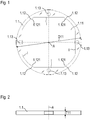
- the invention is based on a rotary encoder ( Figure 7 ), which is intended to detect an angular position between a scanning unit 1 according to the invention and a scale element 2 or a scale that can be rotated relative to an axis A.
- the scanning unit 1 has a metal frame 1.1 which, in the exemplary embodiment presented, is made from an aluminum alloy.
- the metal frame 1.1 has an almost circular outer contour and has a first dimension D11 orthogonal to the axis, which corresponds to the maximum outer diameter of the metal frame 1.1.
- the metal frame 1.1 is made of a flat plate with a thickness which corresponds to a second dimension T11 of the metal frame 1.1, cut out.
- the axis A is oriented orthogonally to the metal frame 1.1 or to the end faces of the metal frame 1.1.
- the metal frame 1.1 has an axially continuous first recess 1.11, so that the metal frame 1.1 therefore encloses the continuous first recess 1.11.
- the first recess 1.11 is naturally delimited by an inside I of the metal frame 1.1.
- the inside I of the metal frame 1.1 is oriented parallel to the axis A and surrounds the axis A.
- This inside I has four inwardly projecting elements 1.12 oriented radially towards the axis A, each of which has an edge 1.121 running parallel to the axis A.
- the inside I has no shoulder or projection which would not run over the entire second extension T11 or over the entire thickness of the metal frame 1.1.
- the continuous first recess 1.11 can therefore be produced, for example, by a punching process or a laser or water jet cutting process.
- the metal frame 1.1 also has second recesses 1.13, which are designed as fastening bores in the exemplary embodiment presented.
- the metal frame 1.1 accordingly has a disk-shaped or annular shape.
- the first dimension D11 is 17.5 times greater than the second dimension T11.
- Lines virtually parallel to the axis can be arranged on the inside I of the metal frame 1.1 or on the first recess 1.11. Each of these lines has the same distance from the axis A over the second extension T11.
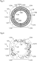
- the scanning unit 1 also comprises a printed circuit board 1.2.
- the circuit board 1.2 is particularly in the Figures 3 and 4 shown. Accordingly, the printed circuit board 1.2 has a substrate 1.21 which, in the exemplary embodiment presented, has a plurality of layers.
- the substrate 1.21 has a first surface 1.211, and a second surface 1.212, the second surface 1.212 being arranged opposite to the first 1.211, as well as a circumferential third surface 1.213, which can also be referred to as a lateral surface.
- a pick-up arrangement 1.23 according to FIG Figure 3 arranged.
- the rotary encoder is based on an inductive scanning principle, so that the sensor arrangement 1.23 has two receiver tracks 1.231, 1.232, each of the receiver tracks 1.231, 1.232 comprising two receiver conductor tracks 1.2311, 1.2312, 1.2321, 1.2322.
- the receiver conductor tracks 1.2311, 1.2312, 1.2321, 1.2322 run on different levels with plated-through holes, so that undesired short circuits are avoided at crossing points.
- at least two layers are provided in the circuit board or substrate structure.
- the receiver conductor tracks 1.2311, 1.2312, 1.2321, 1.2322 have a spatially periodic course that is essentially sinusoidal or sinusoidal.
- Receiver conductor tracks 1.2311, 1.2312, 1.2321, 1.2322, which belong to the same receiver track 1.231, 1.232, are arranged offset relative to one another along the circumferential direction.
- adjacent receiver conductor tracks 1.2311, 1.2312, 1.2321, 1.2322 are offset from one another by 1/4 of the full sine period (by ⁇ / 2 or 90 ° along the first direction x).
- the receiver conductor tracks 1.2311, 1.2312, 1.2321, 1.2322 are electrically connected in such a way that they can ultimately deliver signals that are phase-shifted by 90 ° in the circumferential direction with regard to position determination.
- the scanning unit 1 comprises excitation conductor tracks 1.24, which are also arranged on the first surface 1.211 and enclose the receiver conductor tracks 1.2311, 1.2312, 1.2321, 1.2322.
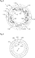
- An electronic circuit is required to operate the excitation conductor tracks 1.24 and to process the signals received from the receiver conductor tracks 1.2311, 1.2312, 1.2321, 1.2322.
- an electrical coupling piece 1.221 for producing a plug connection with a mating connector of a cable is mounted on the second surface 1.212.
- the printed circuit board 1.2 has four concave indentations 1.214 on the jacket surface side, that is to say on its circumferential jacket side.
- the printed circuit board 1.2 or the substrate 1.21 is pressed into the metal frame 1.1 so that the edges 1.121 of the protruding elements 1.12 dig into the substrate 1.21 in the area of the indentations 1.214 ( Figure 5 ).
- the substrate 1.21 is therefore oversized at the contact points with the metal frame 1.1.
- the protruding elements 1.12 engage in the concave indentations 1.214 in such a way that the substrate 1.21 is fixed in the metal frame 1.1 under mechanical tension.
- the circuit board 1.2 with the sensor arrangement 1.23 is fixed exactly relative to the metal frame 1.1 or to the second recesses 1.13 in all spatial directions, which is important with regard to the measuring accuracy of the rotary encoder.
- the scale element 2 is shown in a top view.
- the scale element 2 consists of a substrate 2.3, which in the illustrated embodiment is made of epoxy resin and on which two graduation tracks 2.1, 2.2 are arranged.
- the graduation tracks 2.1, 2.2 are ring-shaped and are arranged concentrically with respect to the axis A with different diameters on the substrate.
- the two graduation tracks 2.1, 2.2 each consist of a periodic sequence of alternately arranged electrically conductive graduation areas 2.11, 2.21 and non-conductive graduation areas 2.12, 2.22.
- copper was applied to the material for the electrically conductive graduation areas 2.11, 2.21 Substrate 2.3 applied.
- the substrate 2.3 was not coated in the non-conductive graduation areas 2.12, 2.22.
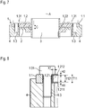
- a rotary encoder which comprises the scanning unit 1 and the scale element 2.
- the scanning unit 1 is fixed to a first machine part 4, here a flange, with the aid of fastening elements 1.3 which, in the exemplary embodiment presented, are designed as screws.
- the fastening elements 1.3 are inserted through the second recesses 1.13 so that they penetrate the second recesses 1.13.
- the fastening elements 1.3 each have a section 1.31 which protrudes inwardly beyond the substrate 1.21 and which is the head of the screw in the exemplary embodiment presented.
- the protruding section 1.31 projects beyond the substrate 1.21 over a length X1.
- the fastening elements 1.3 thus press the metal frame 1.1 against the flange 4 and at the same time secure the circuit board 1.2 in the axial direction.
- the circuit board 1.2 or the substrate 1.21 was pressed into the metal frame 1.1 in the course of the assembly of the scanning unit 1 in the direction of the axis A so that the metal frame 1.1 has a first axial protrusion H1 with respect to the first surface 1.211 of the substrate 1.21.
- the first surface 1.211 of the substrate 1.21 is that side of the printed circuit board 1.2 on which the sensor arrangement 1.23 and the excitation conductor tracks 1.24 are arranged.
- the first axial projection H1 relates to the end face of the metal frame and the first face 1.211 of the substrate 1.21.
- the circuit board 1.2 is arranged in the metal frame 1.1 in such a way that the metal frame 1.1 has a second axial projection H2 with respect to the second surface 1.212 of the substrate 1.21.
- the metal frame 1.1 thus has a larger second dimension T11 in the direction of the axis A than the substrate 1.21, which has a third dimension T121 in the direction of the axis A.
- the substrate 1.21 is therefore complete surrounded by the metal frame 1.1 or by the inside I of the metal frame 1.1 and does not protrude axially at any point beyond the outer contour of the metal frame 1.1.
- the scanning unit 1 and the scale element 2 face one another with an axial distance C or an axial air gap.
- the axial protrusion H1 can be set easily but very precisely during assembly, for example by means of suitable assembly devices with stops, so that the desired distance C can also be easily set with a high degree of accuracy. This increases the measuring accuracy of the encoder.
- the excitation conductor tracks 1.24 generate a time-changing electromagnetic excitation field in the area of the scanned graduation structures.
- the excitation conductor tracks 1.24 are designed as a plurality of planar-parallel, current-carrying individual conductor tracks.
- the electronic circuit of the scanning unit 1 with the electronic components 1.22 works not only as an evaluation element, but also as an excitation control element, under whose control the excitation current is generated, which then flows through the excitation conductor tracks 1.24.
- a tubular or cylindrical electromagnetic field is formed around the respective excitation conductor track 1.24.
- the field lines of the resulting electromagnetic field run in the form of concentric circles around the exciter conductor tracks 1.24, the direction of the field lines depending in a known manner on the direction of current in the exciter conductor tracks 1.24.
- Eddy currents are induced in the area of the electrically conductive graduation areas 2.11, 2.21, so that a modulation of the field dependent on the angular position is achieved.
- the relative angular position can be measured in relation to axis A as the axis of rotation.
- the pairs of receiver conductor tracks 1.2311, 1.2312, 1.2321, 1.2322 are arranged within their receiver track 1.231, 1.232 in such a way that they each deliver signals that are 90 ° out of phase so that the direction of rotation can also be determined.
Landscapes
- Physics & Mathematics (AREA)
- General Physics & Mathematics (AREA)
- Transmission And Conversion Of Sensor Element Output (AREA)
Abstract
Die Erfindung betrifft eine Abtasteinheit (1) zur Abtastung eines relativ zur Abtasteinheit (1) um eine Achse (A) drehbaren Skalenelements (2). Die Abtasteinheit (1) umfasst eine Leiterplatte (1.2), die ein Substrat (1.21) aufweist, welches eine erste Fläche (1.211), eine der ersten Fläche (1.211) gegenüberliegende zweite Fläche (1.212) sowie eine umlaufende dritte Fläche (1.213) aufweist. An der ersten Fläche (1.211) ist eine Aufnehmeranordnung (1.23) angeordnet und an der zweiten Fläche (1.212) sind elektronische Bauteile (1.22) montiert. Die dritte Fläche (1.213) weist mehrere konkave Einbuchtungen (1.214) auf. Die Abtasteinheit (1) umfasst zudem einen Metallrahmen (1.1), der eine durchgängige erste Ausnehmung (1.11) aufweist, die von einer Innenseite (I) des Metallrahmens (1.1) radial begrenzt ist, wobei die Innenseite (I) mehrere nach innen ragende Elemente (1.12) aufweist. Die nach innen ragenden Elemente (1.12) greifen derart in die konkaven Einbuchtungen (1.214) ein, dass das Substrat (1.21) unter mechanischer Spannung im Metallrahmen (1.1) fixiert ist. (Figur 5)The invention relates to a scanning unit (1) for scanning a scale element (2) which can be rotated about an axis (A) relative to the scanning unit (1). The scanning unit (1) comprises a printed circuit board (1.2) which has a substrate (1.21) which has a first surface (1.211), a second surface (1.212) opposite the first surface (1.211) and a peripheral third surface (1.213). . A sensor arrangement (1.23) is arranged on the first surface (1.211) and electronic components (1.22) are mounted on the second surface (1.212). The third surface (1.213) has several concave indentations (1.214). The scanning unit (1) also includes a metal frame (1.1) which has a continuous first recess (1.11) which is radially delimited by an inner side (I) of the metal frame (1.1), the inner side (I) having a number of inwardly protruding elements (1.12) has. The inwardly protruding elements (1.12) engage in the concave indentations (1.214) in such a way that the substrate (1.21) is fixed in the metal frame (1.1) under mechanical tension. (figure 5)
Description
Die Erfindung betrifft eine Abtasteinheit zur Abtastung eines relativ zur Abtasteinheit drehbaren Skalenelements gemäß dem Anspruch 1 sowie einen Drehgeber, der mit einer derartigen Abtasteinheit ausgestattet ist.The invention relates to a scanning unit for scanning a scale element rotatable relative to the scanning unit according to claim 1 and to a rotary encoder which is equipped with such a scanning unit.
Drehgeber werden beispielsweise als Winkelmessgeräte zur Bestimmung der Winkelposition zweier relativ zueinander drehbarer Maschinenteile verwendet.Rotary encoders are used, for example, as angle measuring devices for determining the angular position of two machine parts that can be rotated relative to one another.
Bei induktiven Drehgebern sind häufig Erregerleiterbahnen und Empfängerspuren etwa in Form von Leiterbahnen auf einer gemeinsamen meist mehrlagigen Leiterplatte aufgebracht, die beispielsweise mit einem Stator eines Drehgebers fest verbunden ist. Dieser Leiterplatte gegenüber befindet sich ein Skalenelement, auf dem Teilungsstrukturen aufgebracht sind, und welches mit dem Rotor des Drehgebers drehfest verbunden ist. Wenn an den Erregerspulen ein zeitlich wechselnder elektrischer Erregerstrom angelegt wird, werden in den Empfängerspulen während der Relativdrehung zwischen Rotor und Stator von der Winkelposition abhängige Signale erzeugt. Diese Signale werden dann in einer Auswerteelektronik weiterverarbeitet.In inductive rotary encoders, exciter traces and receiver tracks are often applied, for example in the form of conductive traces, to a common, mostly multilayer printed circuit board that is firmly connected, for example, to a stator of a rotary encoder. Opposite this circuit board is a scale element on which graduation structures are applied and which is connected to the rotor of the rotary encoder in a rotationally fixed manner. If a time-changing electrical excitation current is applied to the excitation coils, signals that are dependent on the angular position are generated in the receiver coils during the relative rotation between the rotor and stator. These signals are then processed further in evaluation electronics.
Bei Drehgebern, die nach einem optischen Prinzip arbeiten, wird häufig ein Lichtstrahl an einer drehbaren Scheibe, welche Teilungsstrukturen aufweist, reflektiert, wobei danach das reflektierte und modulierte Licht von einem Lichtdetektor empfangen wird. Die empfangene Lichtintensität beinhaltet die Information über die relative Winkelstellung.In the case of rotary encoders that work according to an optical principle, a light beam is often transmitted to a rotatable disk, which has graduation structures, reflected, after which the reflected and modulated light is received by a light detector. The received light intensity contains the information about the relative angular position.
Häufig werden derartige Drehgeber als Messgeräte für elektrische Antriebe, zur Bestimmung der Relativbewegung beziehungsweise der Relativlage von entsprechenden Maschinenteilen eingesetzt. In diesem Fall werden die erzeugten Winkelpositionswerte einer Folgeelektronik zur Ansteuerung der Antriebe über eine entsprechende Schnittstellenanordnung zugeführt.Such rotary encoders are often used as measuring devices for electrical drives to determine the relative movement or the relative position of corresponding machine parts. In this case, the generated angular position values are fed to subsequent electronics for controlling the drives via a corresponding interface arrangement.
In der
Der Erfindung liegt die Aufgabe zugrunde eine Abtasteinheit zu schaffen, die wirtschaftlich herstellbar ist und eine kompakte Bauform aufweist und dennoch eine hohe Messgenauigkeit ermöglicht.The invention is based on the object of creating a scanning unit that can be manufactured economically and has a compact design and yet enables high measurement accuracy.
Diese Aufgabe wird erfindungsgemäß durch die Merkmale des Anspruches 1 gelöst.According to the invention, this object is achieved by the features of claim 1.
Demnach ist die Abtasteinheit zur Abtastung eines relativ zur Abtasteinheit um eine Achse drehbaren Skalenelements geeignet, wobei die Abtasteinheit einen Metallrahmen und eine Leiterplatte umfasst. Die Leiterplatte weist ein Substrat auf, welches eine erste Fläche, eine der ersten Fläche gegenüberliegende zweite Fläche sowie eine umlaufende dritte Fläche aufweist. An der ersten Fläche ist eine Aufnehmeranordnung beziehungsweise eine Sensoranordnung angeordnet. An beziehungsweise auf der zweiten Fläche sind elektronische Bauteile montiert. Die dritte Fläche weist mehrere konkave Einbuchtungen auf. Der Metallrahmen weist eine durchgängige erste Ausnehmung auf, die von einer Innenseite des Metallrahmens radial begrenzt ist, wobei die Innenseite mehrere nach innen ragende Elemente aufweist. Die Innenseite des Metallrahmens umschließt die Einbuchtungen der umlaufenden dritte Fläche des Substrats. Die nach innen ragenden Elemente greifen derart in die konkaven Einbuchtungen ein, dass das Substrat unter mechanischer Spannung im Metallrahmen fixiert ist.Accordingly, the scanning unit is suitable for scanning a scale element rotatable about an axis relative to the scanning unit, the scanning unit comprising a metal frame and a circuit board. The circuit board has a substrate which has a first surface, a second surface opposite the first surface and a circumferential third surface. A pick-up arrangement or a sensor arrangement is arranged on the first surface. Electronic components are mounted on or on the second surface. The third surface has several concave indentations. The metal frame has a continuous first recess which is radially delimited by an inside of the metal frame, the Inside has several inwardly protruding elements. The inside of the metal frame encloses the indentations of the circumferential third surface of the substrate. The inwardly protruding elements engage in the concave indentations in such a way that the substrate is fixed in the metal frame under mechanical tension.
Insbesondere ist unter der durchgängigen ersten Ausnehmung eine Ausnehmung zu verstehen, die keinen Absatz aufweist, so dass also entlang jeder zur Achse parallelen Linie auf der Innenseite der Ausnehmung der radiale Abstand zur Achse für ein und dieselbe Linie stets gleich groß ist.In particular, the continuous first recess is to be understood as a recess that has no shoulder, so that along each line parallel to the axis on the inside of the recess, the radial distance to the axis is always the same for one and the same line.
In diesem Zusammenhang resultieren insbesondere die mechanischen Spannungen aus radial orientierten Kräften, also aus Klemmkräften in Richtung der Achse.In this context, the mechanical stresses in particular result from radially oriented forces, i.e. from clamping forces in the direction of the axis.
Häufig wird das Substrat zusätzlich zur beschriebenen Klemmung infolge der erzeugten mechanischen Spannungen noch durch eine redundante Klebeverbindung fixiert beziehungsweise gesichert.In addition to the described clamping, the substrate is often fixed or secured by a redundant adhesive connection as a result of the mechanical stresses generated.
Insbesondere kann die Abtasteinheit vier nach innen ragende Elemente aufweisen, die derart in die konkaven Einbuchtungen eingreifen, dass die Leiterplatte beziehungsweise das Substrat unter mechanischer Spannung im Metallrahmen fixiert ist.In particular, the scanning unit can have four inwardly projecting elements which engage in the concave indentations in such a way that the circuit board or the substrate is fixed in the metal frame under mechanical tension.
Mit Vorteil weisen die nach innen ragenden Elemente jeweils eine parallel zur Achse verlaufende Kante beziehungsweise Schneide auf.The inwardly projecting elements advantageously each have an edge or cutting edge running parallel to the axis.
Gemäß einer weiteren Ausgestaltung der Erfindung weist der Metallrahmen eine scheibenförmige beziehungsweise in erster Näherung ringförmige Gestalt auf. Somit weist der Metallrahmen insbesondere eine Gestalt eines näherungsweisen Hohlzylinders auf, dessen Durchmesser um ein Vielfaches höher ist als seine Dicke. Insbesondere ist der Metallrahmen aus einer ebenen Platte herausgearbeitet, so dass die ringförmigen Deckflächen beziehungsweise die Stirnflächen des Metallrahmens keine auskragenden Bereiche aufweisen. Vielmehr sind die Stirnflächen des Metallrahmens eben und parallel zueinander orientiert. Vorzugsweise ist der Metallrahmen umlaufend geschlossen ausgestaltet. Er kann aber gegebenenfalls auch nicht geschlossen ausgeführt sein, also einen Spalt aufweisen, dessen Spaltbreite sich in Umfangsrichtung erstreckt.According to a further embodiment of the invention, the metal frame has a disk-shaped or, in a first approximation, annular shape. Thus, the metal frame in particular has the shape of an approximately hollow cylinder, the diameter of which is many times greater than its thickness. In particular, the metal frame is machined from a flat plate so that the annular cover surfaces or the end surfaces of the metal frame do not have any protruding areas. Rather, the end faces of the metal frame are flat and parallel oriented towards each other. The metal frame is preferably designed to be closed all round. However, it can optionally also not be designed to be closed, that is to say have a gap, the gap width of which extends in the circumferential direction.
Die Stirnflächen (die ringförmigen Deckflächen) des Metallrahmens sind im Übrigen orthogonal zur Achse angeordnet.The end faces (the annular top faces) of the metal frame are otherwise arranged orthogonally to the axis.
Die Innenseite des Metallrahmens und die umlaufende Außenseite beziehungsweise Außenkontur des Metallrahmens sind bezüglich ein und desselben Punktes, der vorzugsweise auf der Achse zu liegen kommt, punktsymmetrisch zueinander angeordnet.The inside of the metal frame and the circumferential outside or outside contour of the metal frame are arranged point-symmetrically to one another with respect to one and the same point, which preferably comes to lie on the axis.
Vorteilhafterweise weist der Metallrahmen in einer Richtung senkrecht zur Achse eine erste Ausdehnung auf, die als Durchmesser oder als maximaler Durchmesser gesehen werden kann. Der Metallrahmen weist zudem in Richtung der Achse eine zweite Ausdehnung auf, die auch als Dicke bezeichnet werden kann. Die erste Ausdehnung ist mindestens fünfmal größer als die zweite Ausdehnung, mit Vorteil mindestens zehnmal größer, insbesondere mindesten zwölfmal größer.The metal frame advantageously has a first dimension in a direction perpendicular to the axis, which can be seen as a diameter or as a maximum diameter. The metal frame also has a second dimension in the direction of the axis, which can also be referred to as the thickness. The first expansion is at least five times larger than the second expansion, advantageously at least ten times larger, in particular at least twelve times larger.
Mit Vorteil weist der Metallrahmen eine weitgehend kreisförmige Außenkontur auf.The metal frame advantageously has a largely circular outer contour.
Vorteilhafterweise ist die Leiterplatte im Metallrahmen derart angeordnet, dass der Metallrahmen bezüglich der ersten Fläche des Substrats einen ersten axialen Überstand aufweist.The circuit board is advantageously arranged in the metal frame in such a way that the metal frame has a first axial protrusion with respect to the first surface of the substrate.
In weiterer Ausgestaltung der Erfindung ist die Leiterplatte im Metallrahmen derart angeordnet, dass der Metallrahmen bezüglich der zweiten Fläche des Substrats einen zweiten axialen Überstand aufweist. Es können aber die elektronischen Bauelemente in Richtung der Achse über die Kontur des Metallrahmens herausragen.In a further embodiment of the invention, the circuit board is arranged in the metal frame in such a way that the metal frame has a second axial protrusion with respect to the second surface of the substrate. However, the electronic components can protrude beyond the contour of the metal frame in the direction of the axis.
Mit Vorteil weist der Metallrahmen zweite Ausnehmungen, die insbesondere als Bohrungen ausgestaltet sein können, zur Befestigung an einem Maschinenteil auf. Zudem kann die Abtasteinheit Befestigungselemente umfassen, welche die zweiten Ausnehmungen durchdringen, wobei die Befestigungselemente jeweils einen nach innen über das Substrat auskragenden Abschnitt aufweisen. Somit kann durch die Befestigungselemente nicht nur den Metallrahmen fixiert werden, sondern es kann auch gleichzeitig eine axiale Sicherung der Leiterplatte erreicht werden.The metal frame advantageously has second recesses, which can in particular be designed as bores, for attachment to a machine part. In addition, the scanning unit can comprise fastening elements which penetrate the second recesses, the fastening elements each having a section protruding inwardly beyond the substrate. Thus, not only can the metal frame be fixed by the fastening elements, but the printed circuit board can also be secured axially at the same time.
Vorteilhafterweise weist der Metallrahmen in Richtung der Achse eine zweite Ausdehnung (Dicke des Metallrahmens) und das Substrat weist in Richtung der Achse eine dritte Ausdehnung (Dicke des Substrats) auf, wobei die zweite Ausdehnung größer ist als die dritte Ausdehnung.The metal frame advantageously has a second dimension (thickness of the metal frame) in the direction of the axis and the substrate has a third dimension (thickness of the substrate) in the direction of the axis, the second dimension being greater than the third dimension.
Gemäß einem weiteren Aspekt umfasst die Erfindung auch einen Drehgeber mit einer Abtasteinheit sowie einem Skalenelement, wobei die erste Fläche des Substrats dem Skalenelement mit einem sich in Richtung der Achse erstreckendem Abstand gegenüber liegend angeordnet ist.According to a further aspect, the invention also comprises a rotary encoder with a scanning unit and a scale element, the first surface of the substrate being arranged opposite the scale element at a distance extending in the direction of the axis.
Prinzipiell wird zwischen Drehgebern mit Eigenlagerung und Drehgebern ohne Eigenlagerung, im Folgenden als lagerlose Drehgeber bezeichnet, unterschieden. Drehgeber mit Eigenlagerung weisen üblicherweise vergleichsweise kleine Wälzlager auf, so dass die relativ zueinander drehbaren Bauteilgruppen innerhalb des betreffenden Drehgebers in definierter axialer und radialer Position relativ zueinander angeordnet sind. Dagegen muss bei den lagerlosen Drehgebern bei der Montage an einer Maschine darauf geachtet werden, dass die zueinander drehbaren Bauteilgruppen in der richtigen Position insbesondere im korrekten axialen Abstand zueinander festgelegt werden.In principle, a distinction is made between encoders with their own bearings and encoders without their own bearings, hereinafter referred to as bearingless encoders. Rotary encoders with their own bearings usually have comparatively small roller bearings, so that the component groups that can be rotated relative to one another are arranged within the relevant rotary encoder in a defined axial and radial position relative to one another. On the other hand, when installing the bearingless rotary encoders on a machine, care must be taken to ensure that the component groups that can be rotated relative to one another are fixed in the correct position, in particular at the correct axial distance from one another.
Mit Vorteil ist der Drehgeber als ein lagerloser Drehgeber ausgestaltet.The rotary encoder is advantageously designed as a bearingless rotary encoder.
Vorteilhafte Ausbildungen der Erfindung entnimmt man den abhängigen Ansprüchen.Advantageous developments of the invention can be found in the dependent claims.
Weitere Einzelheiten und Vorteile des erfindungsgemäßen Drehgebers ergeben sich aus der nachfolgenden Beschreibung eines Ausführungsbeispiels anhand der beiliegenden Figuren.Further details and advantages of the rotary encoder according to the invention emerge from the following description of an exemplary embodiment with reference to the accompanying figures.
- Figur 1Figure 1
- eine Draufsicht auf einen Metallrahmen der Abtasteinheit,a plan view of a metal frame of the scanning unit,
- Figur 2Figure 2
- eine Seitenansicht auf den Metallrahmen der Abtasteinheit,a side view of the metal frame of the scanning unit,
- Figur 3Figure 3
- eine Draufsicht auf eine Leiterplatte der Abtasteinheit,a plan view of a circuit board of the scanning unit,
- Figur 4Figure 4
-
eine Draufsicht auf die Leiterplatte der Abtasteinheit auf die bezüglich der
Figur 3 gegenüber liegende Seite der Leiterplatte,a plan view of the circuit board of the scanning unit on the related toFigure 3 opposite side of the circuit board, - Figur 5Figure 5
- eine Draufsicht auf die Abtasteinheit,a top view of the scanning unit,
- Figur 6Figure 6
- eine Draufsicht auf ein Skalenelement,a top view of a scale element,
- Figur 7Figure 7
- eine Schnittdarstellung eines Drehgebers im eingebauten Zustand,a sectional view of a rotary encoder in the installed state,
- Figur 8Figure 8
- eine Detailansicht der Schnittdarstellung des Drehgebers im eingebauten Zustand.a detailed view of the sectional view of the rotary encoder in the installed state.
Die Erfindung wird anhand eines Drehgebers (
Insbesondere anhand der
Zur Befestigung an einem Maschinenteil weist der Metallrahmen 1.1 zudem zweite Ausnehmungen 1.13, die im vorgestellten Ausführungsbeispiel als Befestigungsbohrungen ausgestaltet sind, auf.For fastening to a machine part, the metal frame 1.1 also has second recesses 1.13, which are designed as fastening bores in the exemplary embodiment presented.
Der Metallrahmen 1.1 weist demnach eine scheibenförmige beziehungsweise ringförmige Gestalt auf. Dabei ist im vorgestellten Ausführungsbeispiel die erste Ausdehnung D11 17,5mal größer als die zweite Ausdehnung T11. Auf der Innenseite I des Metallrahmens 1.1 beziehungsweise an der ersten Ausnehmung 1.11 können virtuell zur Achse parallele Linien angeordnet werden. Jede dieser Linien hat über die zweite Ausdehnung T11 hinweg den gleichen Abstand zur Achse A.The metal frame 1.1 accordingly has a disk-shaped or annular shape. In the exemplary embodiment presented, the first dimension D11 is 17.5 times greater than the second dimension T11. Lines virtually parallel to the axis can be arranged on the inside I of the metal frame 1.1 or on the first recess 1.11. Each of these lines has the same distance from the axis A over the second extension T11.
Weiterhin umfasst die Abtasteinheit 1 eine Leiterplatte 1.2. Die Leiterplatte 1.2 ist insbesondere in den
An der ersten Fläche 1.211 ist eine Aufnehmeranordnung 1.23 gemäß der
Empfängerleiterbahnen 1.2311, 1.2312, 1.2321, 1.2322, die zur gleichen Empfängerspur 1.231, 1.232 gehören, sind relativ zueinander entlang der Umfangsrichtung versetzt angeordnet. Im vorgestellten Ausführungsbeispiel sind benachbarte Empfängerleiterbahnen 1.2311, 1.2312, 1.2321, 1.2322 um 1/4 der vollen Sinusperiode (um π/2 oder 90° entlang der ersten Richtung x) zueinander versetzt angeordnet. Die Empfängerleiterbahnen 1.2311, 1.2312, 1.2321, 1.2322 sind elektrisch so verschaltet, dass diese letztlich bezüglich der Positionsbestimmung in der Umfangsrichtung um 90° phasenversetzte Signale liefern können.Receiver conductor tracks 1.2311, 1.2312, 1.2321, 1.2322, which belong to the same receiver track 1.231, 1.232, are arranged offset relative to one another along the circumferential direction. In the exemplary embodiment presented, adjacent receiver conductor tracks 1.2311, 1.2312, 1.2321, 1.2322 are offset from one another by 1/4 of the full sine period (by π / 2 or 90 ° along the first direction x). The receiver conductor tracks 1.2311, 1.2312, 1.2321, 1.2322 are electrically connected in such a way that they can ultimately deliver signals that are phase-shifted by 90 ° in the circumferential direction with regard to position determination.
Weiterhin umfasst die Abtasteinheit 1 Erregerleiterbahnen 1.24, die ebenfalls an der ersten Fläche 1.211 angeordnet sind und die Empfängerleiterbahnen 1.2311, 1.2312, 1.2321, 1.2322 umschließen.Furthermore, the scanning unit 1 comprises excitation conductor tracks 1.24, which are also arranged on the first surface 1.211 and enclose the receiver conductor tracks 1.2311, 1.2312, 1.2321, 1.2322.
Zum Betrieb der Erregerleiterbahnen 1.24 und zur Verarbeitung der von den Empfängerleiterbahnen 1.2311, 1.2312, 1.2321, 1.2322 empfangenen Signale ist eine elektronische Schaltung erforderlich. Auf der zweiten Fläche 1.212 der Leiterplatte 1.2, die der ersten Fläche 1.211 gegenüber liegend angeordnet ist, sind elektronische Bauteile 1.22 montiert (in den Figuren sind beispielhaft nur einige wenige elektronische Bauteile mit Bezugszeichen versehen). Diese elektronischen Bauteile 1.22 dienen zur Versorgung der Erregerleiterbahnen 1.24 und zur Verarbeitung der empfangenen Signale. Zudem ist auf der zweiten Fläche 1.212 ein elektrisches Kopplungsstück 1.221 zur Herstellung einer Steckverbindung mit einem Gegenstecker eines Kabels montiert.An electronic circuit is required to operate the excitation conductor tracks 1.24 and to process the signals received from the receiver conductor tracks 1.2311, 1.2312, 1.2321, 1.2322. On the second surface 1.212 of the printed circuit board 1.2, which is arranged opposite the first surface 1.211, electronic components 1.22 are mounted (in the figures, only a few electronic components are provided with reference numerals by way of example). These electronic components 1.22 serve to supply the excitation conductor tracks 1.24 and to process the received signals. In addition, an electrical coupling piece 1.221 for producing a plug connection with a mating connector of a cable is mounted on the second surface 1.212.
Zudem weist die Leiterplatte 1.2 mantelflächenseitig, also an ihrer umlaufenden Mantelseite, vier konkave Einbuchtungen 1.214 auf.In addition, the printed circuit board 1.2 has four concave indentations 1.214 on the jacket surface side, that is to say on its circumferential jacket side.
Im Zuge der Montage der Abtasteinheit 1 wird die Leiterplatte 1.2 beziehungsweise das Substrat 1.21 in den Metallrahmen 1.1 gepresst, so dass sich die Kanten 1.121 der auskragenden Elemente 1.12 in das Substrat 1.21 im Bereich der Einbuchtungen 1.214 eingraben (
In der
In der
Gemäß der
Die Leiterplatte 1.2 beziehungsweise das Substrat 1.21 wurde im Zuge der Montage der Abtasteinheit 1 in Richtung der Achse A genau so weit in den Metallrahmen 1.1 gepresst, dass der Metallrahmen 1.1 bezüglich der ersten Fläche 1.211 des Substrats 1.21 einen ersten axialen Überstand H1 aufweist. Die ersten Fläche 1.211 des Substrats 1.21 ist diejenige Seite der Leiterplatte 1.2, an der die Aufnehmeranordnung 1.23 und die Erregerleiterbahnen 1.24 angeordnet sind. Der erste axiale Überstand H1 bezieht sich auf die Stirnfläche des Metallrahmens und die erste Fläche 1.211 des Substrats 1.21.The circuit board 1.2 or the substrate 1.21 was pressed into the metal frame 1.1 in the course of the assembly of the scanning unit 1 in the direction of the axis A so that the metal frame 1.1 has a first axial protrusion H1 with respect to the first surface 1.211 of the substrate 1.21. The first surface 1.211 of the substrate 1.21 is that side of the printed circuit board 1.2 on which the sensor arrangement 1.23 and the excitation conductor tracks 1.24 are arranged. The first axial projection H1 relates to the end face of the metal frame and the first face 1.211 of the substrate 1.21.
Zudem ist in der
Somit weist der Metallrahmen 1.1 in Richtung der Achse A eine größere zweite Ausdehnung T11 auf als das Substrat 1.21, das in Richtung der Achse A eine dritte Ausdehnung T121 aufweist. Das Substrat 1.21 ist also vollständig vom Metallrahmen 1.1 beziehungsweise von der Innenseite I des Metallrahmens 1.1 umgeben und ragt an keiner Stelle axial über die Außenkontur des Metallrahmens 1.1 hervor.The metal frame 1.1 thus has a larger second dimension T11 in the direction of the axis A than the substrate 1.21, which has a third dimension T121 in the direction of the axis A. The substrate 1.21 is therefore complete surrounded by the metal frame 1.1 or by the inside I of the metal frame 1.1 and does not protrude axially at any point beyond the outer contour of the metal frame 1.1.
Im zusammengebauten Zustand gemäß der
Bei einer Relativdrehung zwischen dem Skalenelement 2 und der Abtasteinheit 1 wird in Aufnehmeranordnung 1.23 insbesondere in den Empfängerleiterbahnen 1.2311, 1.2312, 1.2321, 1.2322 ein von der jeweiligen Winkelposition abhängiges Signal durch Induktionseffekte erzeugt. Voraussetzung für die Bildung von entsprechenden Signalen ist, dass die Erregerleiterbahnen 1.24 ein zeitlich wechselndes elektromagnetisches Erregerfeld im Bereich der abgetasteten Teilungsstrukturen erzeugen. Im dargestellten Ausführungsbeispiel sind die Erregerleiterbahnen 1.24 als mehrere planar-parallele stromdurchflossene Einzel-Leiterbahnen ausgebildet. Die elektronische Schaltung der Abtasteinheit 1 mit den elektronischen Bauteilen 1.22 arbeitet nicht nur als Auswerteelement, sondern auch als Erregerkontrollelement, unter dessen Kontrolle der Erregerstrom erzeugt wird, welcher dann durch die Erregerleiterbahnen 1.24 fließt.In the event of a relative rotation between the
Werden die Erregerleiterbahnen 1.24 bestromt, so bildet sich um die jeweilige Erregerleiterbahn 1.24 ein schlauch- bzw. zylinderförmig orientiertes elektromagnetisches Feld aus. Die Feldlinien des resultierenden elektromagnetischen Feldes verlaufen in Form konzentrischer Kreise um die Erregerleiterbahnen 1.24, wobei die Richtung der Feldlinien in bekannter Art und Weise von der Stromrichtung in den Erregerleiterbahnen 1.24 abhängt. Im Bereich der elektrisch leitfähigen Teilungsbereiche 2.11, 2.21 werden Wirbelströme induziert, so dass eine von der Winkelstellung abhängige Modulation des Feldes erreicht wird. Entsprechend kann durch die Empfängerspuren 1.231, 1.232 jeweils die relative Winkelstellung bezogen auf die Achse A als Drehachse gemessen werden. Die Paare von Empfängerleiterbahnen 1.2311, 1.2312, 1.2321, 1.2322 sind innerhalb ihrer Empfängerspur 1.231, 1.232 so angeordnet, dass diese jeweils um 90° phasenversetzte Signale liefern, so dass auch eine Bestimmung der Drehrichtung vorgenommen werden kann.If the excitation conductor tracks 1.24 are energized, a tubular or cylindrical electromagnetic field is formed around the respective excitation conductor track 1.24. The field lines of the resulting electromagnetic field run in the form of concentric circles around the exciter conductor tracks 1.24, the direction of the field lines depending in a known manner on the direction of current in the exciter conductor tracks 1.24. Eddy currents are induced in the area of the electrically conductive graduation areas 2.11, 2.21, so that a modulation of the field dependent on the angular position is achieved. Correspondingly, through the recipient tracks 1.231, 1.232, the relative angular position can be measured in relation to axis A as the axis of rotation. The pairs of receiver conductor tracks 1.2311, 1.2312, 1.2321, 1.2322 are arranged within their receiver track 1.231, 1.232 in such a way that they each deliver signals that are 90 ° out of phase so that the direction of rotation can also be determined.
Claims (11)
die Innenseite (I) des Metallrahmens (1.1) die Einbuchtungen (1.214) des Substrats (1.21) umschließt und
die nach innen ragenden Elemente (1.12) derart in die konkaven Einbuchtungen (1.214) eingreifen, dass das Substrat (1.21) unter mechanischer Spannung im Metallrahmen (1.1) fixiert ist.
the inside (I) of the metal frame (1.1) encloses the indentations (1.214) of the substrate (1.21) and
the inwardly protruding elements (1.12) engage in the concave indentations (1.214) in such a way that the substrate (1.21) is fixed in the metal frame (1.1) under mechanical tension.
Priority Applications (5)
| Application Number | Priority Date | Filing Date | Title |
|---|---|---|---|
| EP20181310.2A EP3929539B1 (en) | 2020-06-22 | 2020-06-22 | Scanning unit and rotary encoder with same |
| DE102021200441.5A DE102021200441A1 (en) | 2020-06-22 | 2021-01-19 | SCANNING UNIT AND ENCODER EQUIPPED WITH IT |
| JP2021012763A JP2022001860A (en) | 2020-06-22 | 2021-01-29 | Scanning unit and rotary encoder mounted with the same |
| CN202110656792.8A CN113899389A (en) | 2020-06-22 | 2021-06-11 | Scanning unit and rotary encoder equipped with the same |
| US17/348,196 US11506516B2 (en) | 2020-06-22 | 2021-06-15 | Scanning unit and rotary encoder equipped therewith |
Applications Claiming Priority (1)
| Application Number | Priority Date | Filing Date | Title |
|---|---|---|---|
| EP20181310.2A EP3929539B1 (en) | 2020-06-22 | 2020-06-22 | Scanning unit and rotary encoder with same |
Publications (2)
| Publication Number | Publication Date |
|---|---|
| EP3929539A1 true EP3929539A1 (en) | 2021-12-29 |
| EP3929539B1 EP3929539B1 (en) | 2022-08-24 |
Family
ID=71120035
Family Applications (1)
| Application Number | Title | Priority Date | Filing Date |
|---|---|---|---|
| EP20181310.2A Active EP3929539B1 (en) | 2020-06-22 | 2020-06-22 | Scanning unit and rotary encoder with same |
Country Status (5)
| Country | Link |
|---|---|
| US (1) | US11506516B2 (en) |
| EP (1) | EP3929539B1 (en) |
| JP (1) | JP2022001860A (en) |
| CN (1) | CN113899389A (en) |
| DE (1) | DE102021200441A1 (en) |
Citations (5)
| Publication number | Priority date | Publication date | Assignee | Title |
|---|---|---|---|---|
| DE102007014781B3 (en) * | 2007-03-28 | 2008-05-15 | Bühler Motor GmbH | Encoder arrangement for direct current motor, has optical sensor with retaining slot opened to motor shaft, and printed circuit board with another slot, which opens from side of direct current motor to edge of board |
| EP2674764A1 (en) * | 2012-06-13 | 2013-12-18 | Aktiebolaget SKF | Method for producing a sensor unit, sensor unit and instrumented bearing comprising such a sensor unit |
| US20180375405A1 (en) * | 2017-06-23 | 2018-12-27 | Nidec Sankyo Corporation | Motor |
| EP3505258A1 (en) * | 2018-01-02 | 2019-07-03 | Sigma Laborzentrifugen GmbH | Laboratory centrifuge |
| DE102018202239A1 (en) | 2018-02-14 | 2019-08-14 | Dr. Johannes Heidenhain Gmbh | Bearing angle measuring device |
Family Cites Families (5)
| Publication number | Priority date | Publication date | Assignee | Title |
|---|---|---|---|---|
| US5084791A (en) * | 1988-05-10 | 1992-01-28 | Quantum Corporation | Head position control system for fixed drive including position encoder, temperature sensor and embedded fine servo information |
| DE102006026543B4 (en) * | 2006-06-07 | 2010-02-04 | Vogt Electronic Components Gmbh | Position encoder and associated method for detecting a position of a rotor of a machine |
| TWI638241B (en) * | 2012-03-26 | 2018-10-11 | 日商尼康股份有限公司 | Substrate processing apparatus, processing apparatus and device manufacturing method |
| DE102016101965A1 (en) * | 2016-02-04 | 2017-08-10 | Fraba B.V. | Method for calibrating a rotary encoder and rotary encoder for determining a corrected angular position |
| US10481269B2 (en) * | 2017-12-07 | 2019-11-19 | Ouster, Inc. | Rotating compact light ranging system |
-
2020
- 2020-06-22 EP EP20181310.2A patent/EP3929539B1/en active Active
-
2021
- 2021-01-19 DE DE102021200441.5A patent/DE102021200441A1/en active Pending
- 2021-01-29 JP JP2021012763A patent/JP2022001860A/en active Pending
- 2021-06-11 CN CN202110656792.8A patent/CN113899389A/en active Pending
- 2021-06-15 US US17/348,196 patent/US11506516B2/en active Active
Patent Citations (5)
| Publication number | Priority date | Publication date | Assignee | Title |
|---|---|---|---|---|
| DE102007014781B3 (en) * | 2007-03-28 | 2008-05-15 | Bühler Motor GmbH | Encoder arrangement for direct current motor, has optical sensor with retaining slot opened to motor shaft, and printed circuit board with another slot, which opens from side of direct current motor to edge of board |
| EP2674764A1 (en) * | 2012-06-13 | 2013-12-18 | Aktiebolaget SKF | Method for producing a sensor unit, sensor unit and instrumented bearing comprising such a sensor unit |
| US20180375405A1 (en) * | 2017-06-23 | 2018-12-27 | Nidec Sankyo Corporation | Motor |
| EP3505258A1 (en) * | 2018-01-02 | 2019-07-03 | Sigma Laborzentrifugen GmbH | Laboratory centrifuge |
| DE102018202239A1 (en) | 2018-02-14 | 2019-08-14 | Dr. Johannes Heidenhain Gmbh | Bearing angle measuring device |
Also Published As
| Publication number | Publication date |
|---|---|
| DE102021200441A1 (en) | 2021-12-23 |
| CN113899389A (en) | 2022-01-07 |
| EP3929539B1 (en) | 2022-08-24 |
| US11506516B2 (en) | 2022-11-22 |
| JP2022001860A (en) | 2022-01-06 |
| US20210396552A1 (en) | 2021-12-23 |
Similar Documents
| Publication | Publication Date | Title |
|---|---|---|
| EP3355032B1 (en) | Sensor for position measurement | |
| EP2743649B1 (en) | Inductive position measurement device | |
| EP3961158B1 (en) | Scanning unit and inductive position measuring device with such a scanning unit | |
| EP1927823B1 (en) | Rotary encoder | |
| EP1927824B1 (en) | Rotary encoder | |
| EP3495781B1 (en) | Inductive position measurement device | |
| EP4012350B1 (en) | Scanning element and inductive position measuring device with the same | |
| EP3534121B1 (en) | Multi-turn rotary encoder | |
| EP1906153A2 (en) | Rotary encoder and method for its operation | |
| EP4012351B1 (en) | Scanning element and inductive position measuring device with the same | |
| EP3683551B1 (en) | Sampling unit for an angle measuring device | |
| EP3702737B1 (en) | Scanning unit for scanning an angle scale and angle measuring device with such a scanning unit | |
| EP3399284A1 (en) | Sensor unit for position measurement | |
| EP3929539B1 (en) | Scanning unit and rotary encoder with same | |
| EP4170289B1 (en) | Inductive angle measuring device | |
| EP3683552B1 (en) | Sampling unit for an angle measuring device | |
| EP4230967B1 (en) | Scanning element and inductive position measuring device with the same | |
| EP3904836A1 (en) | Inductive position measurement device | |
| EP4336148A1 (en) | Scanning element and inductive position measuring device comprising said scanning element | |
| EP4086584B1 (en) | Assembly with a rotary encoder and a tolerance sleeve | |
| EP4273507A1 (en) | Scanning element and inductive position measuring device with the same | |
| EP3657133A1 (en) | Sensor unit and position measuring device with this sensor unit |
Legal Events
| Date | Code | Title | Description |
|---|---|---|---|
| PUAI | Public reference made under article 153(3) epc to a published international application that has entered the european phase |
Free format text: ORIGINAL CODE: 0009012 |
|
| STAA | Information on the status of an ep patent application or granted ep patent |
Free format text: STATUS: REQUEST FOR EXAMINATION WAS MADE |
|
| 17P | Request for examination filed |
Effective date: 20200622 |
|
| AK | Designated contracting states |
Kind code of ref document: A1 Designated state(s): AL AT BE BG CH CY CZ DE DK EE ES FI FR GB GR HR HU IE IS IT LI LT LU LV MC MK MT NL NO PL PT RO RS SE SI SK SM TR |
|
| B565 | Issuance of search results under rule 164(2) epc |
Effective date: 20201130 |
|
| GRAP | Despatch of communication of intention to grant a patent |
Free format text: ORIGINAL CODE: EPIDOSNIGR1 |
|
| STAA | Information on the status of an ep patent application or granted ep patent |
Free format text: STATUS: GRANT OF PATENT IS INTENDED |
|
| RIC1 | Information provided on ipc code assigned before grant |
Ipc: G01D 5/20 20060101ALN20220420BHEP Ipc: G01D 11/24 20060101ALI20220420BHEP Ipc: G01D 5/244 20060101AFI20220420BHEP |
|
| INTG | Intention to grant announced |
Effective date: 20220510 |
|
| GRAS | Grant fee paid |
Free format text: ORIGINAL CODE: EPIDOSNIGR3 |
|
| GRAA | (expected) grant |
Free format text: ORIGINAL CODE: 0009210 |
|
| STAA | Information on the status of an ep patent application or granted ep patent |
Free format text: STATUS: THE PATENT HAS BEEN GRANTED |
|
| RBV | Designated contracting states (corrected) |
Designated state(s): AL AT BE BG CH CY CZ DE DK EE ES FI FR GB GR HR HU IE IS IT LI LT LU LV MC MK MT NL NO PL PT RO RS SE SI SK SM TR |
|
| AK | Designated contracting states |
Kind code of ref document: B1 Designated state(s): AL AT BE BG CH CY CZ DE DK EE ES FI FR GB GR HR HU IE IS IT LI LT LU LV MC MK MT NL NO PL PT RO RS SE SI SK SM TR |
|
| REG | Reference to a national code |
Ref country code: CH Ref legal event code: EP |
|
| REG | Reference to a national code |
Ref country code: IE Ref legal event code: FG4D Free format text: LANGUAGE OF EP DOCUMENT: GERMAN |
|
| REG | Reference to a national code |
Ref country code: AT Ref legal event code: REF Ref document number: 1513950 Country of ref document: AT Kind code of ref document: T Effective date: 20220915 Ref country code: DE Ref legal event code: R096 Ref document number: 502020001568 Country of ref document: DE |
|
| REG | Reference to a national code |
Ref country code: LT Ref legal event code: MG9D |
|
| REG | Reference to a national code |
Ref country code: NL Ref legal event code: MP Effective date: 20220824 |
|
| PG25 | Lapsed in a contracting state [announced via postgrant information from national office to epo] |
Ref country code: SE Free format text: LAPSE BECAUSE OF FAILURE TO SUBMIT A TRANSLATION OF THE DESCRIPTION OR TO PAY THE FEE WITHIN THE PRESCRIBED TIME-LIMIT Effective date: 20220824 Ref country code: RS Free format text: LAPSE BECAUSE OF FAILURE TO SUBMIT A TRANSLATION OF THE DESCRIPTION OR TO PAY THE FEE WITHIN THE PRESCRIBED TIME-LIMIT Effective date: 20220824 Ref country code: PT Free format text: LAPSE BECAUSE OF FAILURE TO SUBMIT A TRANSLATION OF THE DESCRIPTION OR TO PAY THE FEE WITHIN THE PRESCRIBED TIME-LIMIT Effective date: 20221226 Ref country code: NO Free format text: LAPSE BECAUSE OF FAILURE TO SUBMIT A TRANSLATION OF THE DESCRIPTION OR TO PAY THE FEE WITHIN THE PRESCRIBED TIME-LIMIT Effective date: 20221124 Ref country code: NL Free format text: LAPSE BECAUSE OF FAILURE TO SUBMIT A TRANSLATION OF THE DESCRIPTION OR TO PAY THE FEE WITHIN THE PRESCRIBED TIME-LIMIT Effective date: 20220824 Ref country code: LV Free format text: LAPSE BECAUSE OF FAILURE TO SUBMIT A TRANSLATION OF THE DESCRIPTION OR TO PAY THE FEE WITHIN THE PRESCRIBED TIME-LIMIT Effective date: 20220824 Ref country code: LT Free format text: LAPSE BECAUSE OF FAILURE TO SUBMIT A TRANSLATION OF THE DESCRIPTION OR TO PAY THE FEE WITHIN THE PRESCRIBED TIME-LIMIT Effective date: 20220824 Ref country code: FI Free format text: LAPSE BECAUSE OF FAILURE TO SUBMIT A TRANSLATION OF THE DESCRIPTION OR TO PAY THE FEE WITHIN THE PRESCRIBED TIME-LIMIT Effective date: 20220824 |
|
| PG25 | Lapsed in a contracting state [announced via postgrant information from national office to epo] |
Ref country code: PL Free format text: LAPSE BECAUSE OF FAILURE TO SUBMIT A TRANSLATION OF THE DESCRIPTION OR TO PAY THE FEE WITHIN THE PRESCRIBED TIME-LIMIT Effective date: 20220824 Ref country code: IS Free format text: LAPSE BECAUSE OF FAILURE TO SUBMIT A TRANSLATION OF THE DESCRIPTION OR TO PAY THE FEE WITHIN THE PRESCRIBED TIME-LIMIT Effective date: 20221224 Ref country code: HR Free format text: LAPSE BECAUSE OF FAILURE TO SUBMIT A TRANSLATION OF THE DESCRIPTION OR TO PAY THE FEE WITHIN THE PRESCRIBED TIME-LIMIT Effective date: 20220824 Ref country code: GR Free format text: LAPSE BECAUSE OF FAILURE TO SUBMIT A TRANSLATION OF THE DESCRIPTION OR TO PAY THE FEE WITHIN THE PRESCRIBED TIME-LIMIT Effective date: 20221125 |
|
| PG25 | Lapsed in a contracting state [announced via postgrant information from national office to epo] |
Ref country code: SM Free format text: LAPSE BECAUSE OF FAILURE TO SUBMIT A TRANSLATION OF THE DESCRIPTION OR TO PAY THE FEE WITHIN THE PRESCRIBED TIME-LIMIT Effective date: 20220824 Ref country code: RO Free format text: LAPSE BECAUSE OF FAILURE TO SUBMIT A TRANSLATION OF THE DESCRIPTION OR TO PAY THE FEE WITHIN THE PRESCRIBED TIME-LIMIT Effective date: 20220824 Ref country code: ES Free format text: LAPSE BECAUSE OF FAILURE TO SUBMIT A TRANSLATION OF THE DESCRIPTION OR TO PAY THE FEE WITHIN THE PRESCRIBED TIME-LIMIT Effective date: 20220824 Ref country code: DK Free format text: LAPSE BECAUSE OF FAILURE TO SUBMIT A TRANSLATION OF THE DESCRIPTION OR TO PAY THE FEE WITHIN THE PRESCRIBED TIME-LIMIT Effective date: 20220824 |
|
| REG | Reference to a national code |
Ref country code: DE Ref legal event code: R097 Ref document number: 502020001568 Country of ref document: DE |
|
| PG25 | Lapsed in a contracting state [announced via postgrant information from national office to epo] |
Ref country code: SK Free format text: LAPSE BECAUSE OF FAILURE TO SUBMIT A TRANSLATION OF THE DESCRIPTION OR TO PAY THE FEE WITHIN THE PRESCRIBED TIME-LIMIT Effective date: 20220824 Ref country code: EE Free format text: LAPSE BECAUSE OF FAILURE TO SUBMIT A TRANSLATION OF THE DESCRIPTION OR TO PAY THE FEE WITHIN THE PRESCRIBED TIME-LIMIT Effective date: 20220824 |
|
| PG25 | Lapsed in a contracting state [announced via postgrant information from national office to epo] |
Ref country code: AL Free format text: LAPSE BECAUSE OF FAILURE TO SUBMIT A TRANSLATION OF THE DESCRIPTION OR TO PAY THE FEE WITHIN THE PRESCRIBED TIME-LIMIT Effective date: 20220824 |
|
| PLBE | No opposition filed within time limit |
Free format text: ORIGINAL CODE: 0009261 |
|
| STAA | Information on the status of an ep patent application or granted ep patent |
Free format text: STATUS: NO OPPOSITION FILED WITHIN TIME LIMIT |
|
| PGFP | Annual fee paid to national office [announced via postgrant information from national office to epo] |
Ref country code: DE Payment date: 20230620 Year of fee payment: 4 Ref country code: CZ Payment date: 20230612 Year of fee payment: 4 |
|
| 26N | No opposition filed |
Effective date: 20230525 |
|
| PGFP | Annual fee paid to national office [announced via postgrant information from national office to epo] |
Ref country code: IT Payment date: 20230630 Year of fee payment: 4 Ref country code: CH Payment date: 20230702 Year of fee payment: 4 |
|
| PG25 | Lapsed in a contracting state [announced via postgrant information from national office to epo] |
Ref country code: MC Free format text: LAPSE BECAUSE OF FAILURE TO SUBMIT A TRANSLATION OF THE DESCRIPTION OR TO PAY THE FEE WITHIN THE PRESCRIBED TIME-LIMIT Effective date: 20220824 |
|
| PG25 | Lapsed in a contracting state [announced via postgrant information from national office to epo] |
Ref country code: MC Free format text: LAPSE BECAUSE OF FAILURE TO SUBMIT A TRANSLATION OF THE DESCRIPTION OR TO PAY THE FEE WITHIN THE PRESCRIBED TIME-LIMIT Effective date: 20220824 |
|
| REG | Reference to a national code |
Ref country code: BE Ref legal event code: MM Effective date: 20230630 |
|
| PG25 | Lapsed in a contracting state [announced via postgrant information from national office to epo] |
Ref country code: LU Free format text: LAPSE BECAUSE OF NON-PAYMENT OF DUE FEES Effective date: 20230622 |
|
| REG | Reference to a national code |
Ref country code: IE Ref legal event code: MM4A |
|
| PG25 | Lapsed in a contracting state [announced via postgrant information from national office to epo] |
Ref country code: LU Free format text: LAPSE BECAUSE OF NON-PAYMENT OF DUE FEES Effective date: 20230622 |
|
| PG25 | Lapsed in a contracting state [announced via postgrant information from national office to epo] |
Ref country code: IE Free format text: LAPSE BECAUSE OF NON-PAYMENT OF DUE FEES Effective date: 20230622 |
|
| PG25 | Lapsed in a contracting state [announced via postgrant information from national office to epo] |
Ref country code: IE Free format text: LAPSE BECAUSE OF NON-PAYMENT OF DUE FEES Effective date: 20230622 |