EP3929486A1 - Ensemble de production de flammes - Google Patents
Ensemble de production de flammes Download PDFInfo
- Publication number
- EP3929486A1 EP3929486A1 EP21192134.1A EP21192134A EP3929486A1 EP 3929486 A1 EP3929486 A1 EP 3929486A1 EP 21192134 A EP21192134 A EP 21192134A EP 3929486 A1 EP3929486 A1 EP 3929486A1
- Authority
- EP
- European Patent Office
- Prior art keywords
- helical spring
- rigid support
- flame producing
- assembly according
- producing assembly
- Prior art date
- Legal status (The legal status is an assumption and is not a legal conclusion. Google has not performed a legal analysis and makes no representation as to the accuracy of the status listed.)
- Pending
Links
- 239000000463 material Substances 0.000 claims description 5
- 238000004891 communication Methods 0.000 claims description 4
- 239000012530 fluid Substances 0.000 claims description 4
- 239000011295 pitch Substances 0.000 description 28
- 238000004519 manufacturing process Methods 0.000 description 9
- 238000000034 method Methods 0.000 description 6
- 239000004020 conductor Substances 0.000 description 5
- 230000002349 favourable effect Effects 0.000 description 3
- 210000003811 finger Anatomy 0.000 description 3
- 239000000446 fuel Substances 0.000 description 3
- 239000000203 mixture Substances 0.000 description 3
- 235000021168 barbecue Nutrition 0.000 description 2
- 238000003780 insertion Methods 0.000 description 2
- 230000037431 insertion Effects 0.000 description 2
- 229920005992 thermoplastic resin Polymers 0.000 description 2
- OKTJSMMVPCPJKN-UHFFFAOYSA-N Carbon Chemical compound [C] OKTJSMMVPCPJKN-UHFFFAOYSA-N 0.000 description 1
- 206010014357 Electric shock Diseases 0.000 description 1
- 230000004913 activation Effects 0.000 description 1
- 230000000712 assembly Effects 0.000 description 1
- 238000000429 assembly Methods 0.000 description 1
- 229910052799 carbon Inorganic materials 0.000 description 1
- 235000019504 cigarettes Nutrition 0.000 description 1
- 230000006835 compression Effects 0.000 description 1
- 238000007906 compression Methods 0.000 description 1
- 230000004069 differentiation Effects 0.000 description 1
- 238000009429 electrical wiring Methods 0.000 description 1
- 238000009413 insulation Methods 0.000 description 1
- 238000011031 large-scale manufacturing process Methods 0.000 description 1
- 239000002184 metal Substances 0.000 description 1
- 239000004033 plastic Substances 0.000 description 1
- 229920005989 resin Polymers 0.000 description 1
- 239000011347 resin Substances 0.000 description 1
- 238000007789 sealing Methods 0.000 description 1
- 210000003813 thumb Anatomy 0.000 description 1
Images


Classifications
-
- F—MECHANICAL ENGINEERING; LIGHTING; HEATING; WEAPONS; BLASTING
- F23—COMBUSTION APPARATUS; COMBUSTION PROCESSES
- F23Q—IGNITION; EXTINGUISHING-DEVICES
- F23Q2/00—Lighters containing fuel, e.g. for cigarettes
- F23Q2/28—Lighters characterised by electrical ignition of the fuel
- F23Q2/285—Lighters characterised by electrical ignition of the fuel with spark ignition
- F23Q2/287—Lighters characterised by electrical ignition of the fuel with spark ignition piezoelectric
-
- F—MECHANICAL ENGINEERING; LIGHTING; HEATING; WEAPONS; BLASTING
- F23—COMBUSTION APPARATUS; COMBUSTION PROCESSES
- F23Q—IGNITION; EXTINGUISHING-DEVICES
- F23Q2/00—Lighters containing fuel, e.g. for cigarettes
- F23Q2/16—Lighters with gaseous fuel, e.g. the gas being stored in liquid phase
- F23Q2/162—Lighters with gaseous fuel, e.g. the gas being stored in liquid phase with non-adjustable gas flame
-
- F—MECHANICAL ENGINEERING; LIGHTING; HEATING; WEAPONS; BLASTING
- F23—COMBUSTION APPARATUS; COMBUSTION PROCESSES
- F23Q—IGNITION; EXTINGUISHING-DEVICES
- F23Q2/00—Lighters containing fuel, e.g. for cigarettes
- F23Q2/16—Lighters with gaseous fuel, e.g. the gas being stored in liquid phase
- F23Q2/164—Arrangements for preventing undesired ignition
-
- F—MECHANICAL ENGINEERING; LIGHTING; HEATING; WEAPONS; BLASTING
- F23—COMBUSTION APPARATUS; COMBUSTION PROCESSES
- F23Q—IGNITION; EXTINGUISHING-DEVICES
- F23Q2/00—Lighters containing fuel, e.g. for cigarettes
- F23Q2/16—Lighters with gaseous fuel, e.g. the gas being stored in liquid phase
- F23Q2/162—Lighters with gaseous fuel, e.g. the gas being stored in liquid phase with non-adjustable gas flame
- F23Q2/163—Burners (gas valves)
-
- F—MECHANICAL ENGINEERING; LIGHTING; HEATING; WEAPONS; BLASTING
- F23—COMBUSTION APPARATUS; COMBUSTION PROCESSES
- F23Q—IGNITION; EXTINGUISHING-DEVICES
- F23Q2/00—Lighters containing fuel, e.g. for cigarettes
- F23Q2/16—Lighters with gaseous fuel, e.g. the gas being stored in liquid phase
- F23Q2/173—Valves therefor
-
- F—MECHANICAL ENGINEERING; LIGHTING; HEATING; WEAPONS; BLASTING
- F23—COMBUSTION APPARATUS; COMBUSTION PROCESSES
- F23Q—IGNITION; EXTINGUISHING-DEVICES
- F23Q2/00—Lighters containing fuel, e.g. for cigarettes
- F23Q2/34—Component parts or accessories
- F23Q2/40—Cover fastenings
-
- F—MECHANICAL ENGINEERING; LIGHTING; HEATING; WEAPONS; BLASTING
- F23—COMBUSTION APPARATUS; COMBUSTION PROCESSES
- F23Q—IGNITION; EXTINGUISHING-DEVICES
- F23Q2/00—Lighters containing fuel, e.g. for cigarettes
- F23Q2/34—Component parts or accessories
- F23Q2/42—Fuel containers; Closures for fuel containers
Definitions
- the invention relates to a flame producing assembly and more particularly a utility lighter in which the flame is directed downwards.
- a flame producing assembly can be used for example to ignite candles, barbecue grills, fireplaces or campfires.
- Another aspect of the invention is a method for manufacturing such a flame producing assembly.
- a utility lighter In order to light candles, a utility lighter is directed downwards, contrary to a light for lighting a cigarette for instance, in which the flame is directed upwards. So, to ignite a candle (or other such for example a barbecue grill) while keeping the fingers and especially the thumb of the user away from the flame, the utility lighter must have its flame away from the activation button. Therefore, it is already known to use utility lighters provided with an extended wand at the end of which the flame emanates. Patent document EP0446162B1 discloses such a utility lighter. A utility lighter as already disclosed has several components located inside the extended wand in order to ignite the flame, that leads to a complexity of the assembly during the manufacturing. Therefore, there is a need to provide a utility lighter which is easier to manufacture.
- a flame producing assembly is designed in such a way that it is easy to manufacture and that the flame is ignited away from the finger to a user.
- the flame producing assembly according to the invention comprises a pocket lighter and a sub-unit assembly comprising an extended wand, a rigid support and an helical spring, the pocket lighter being connected to the sub-unit assembly, the pocket lighter comprising a piezoelectric ignition device, the rigid support being located inside the extended wand, the rigid support having an longitudinal inner opening, the extended wand being electrically coupled to the piezoelectric ignition device, the pocket lighter being connected directly to the sub-unit assembly, and the helical spring extending along the longitudinal inner opening.
- Such a configuration of the components of the flame producing assembly has the advantage to be easily assembled to each other.
- one and/or the other of the following features may be incorporated in the flame producing assembly of the invention, alone or in mutual combination:
- Another object of the present invention is a method for manufacturing a flame producing assembly, the flame producing assembly comprising a pocket lighter and sub-unit assembly, the sub-unit assembly being snap-fitted to the pocket lighter.
- a snap-fit assembly of the utility lighter has the advantage to be easily implemented and faster than the assemblies already known.
- the sub-unit assembly comprises an extended wand and a rigid support, and the extended wand and the rigid support are snap-fitted together.
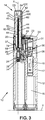
- FIGS 1 and 2 illustrate a utility lighter 10 according to the present invention.
- the utility lighter 10 comprises a pocket lighter 12 and a sub-unit assembly 14.
- the pocket lighter 12 comprises a body 17, a pusher 20 and a cover 35.
- the pocket lighter 12 extends along a longitudinal axis X.
- the length L1 of the pocket lighter 12 along the longitudinal axis X is comprised between 5cm and 12cm. More precisely, the length L1 of the pocket lighter 12 is approximately 8cm.
- the width L2 of the pocket lighter 12 is measurable along a transversal axis Y, which is perpendicular to the longitudinal axis X.
- the width L2 can be comprised between 1,5cm and 3cm. For example, the width L2 can be approximately 2,5cm.
- the pocket lighter 12 further comprises a piezoelectric ignition device 18.
- the pocket lighter 12 is also provided with a pusher 20.
- the piezoelectric ignition device 18 is connected to the pusher 20.
- the connection between the pusher 20 and the piezoelectric ignition device 18 is such that the pusher 20 and a portion of the piezoelectric ignition device 18 which is the closest to the pusher 20 are firmly attached together. Consequently, when a user pushes the pusher 20 inward the pocket lighter 12, the piezoelectric ignition device 18 is compressed to produce an elevated potential difference between its two poles 18- and 18+.
- a first pole 30 is connected to a jet 24 and a second pole 32 is connected to an electrode spring 22.
- the electrode spring 22 is connected at a first end to the pusher 20.
- the second end of the electrode spring 22 is connected to the sub-unit assembly 14.
- the jet 24 comprises an upper end 26 and a lower end 28, regarding the longitudinal axis X.
- the jet 24 is movable along the longitudinal axis X.
- the piezoelectric ignition device 18 provides a potential difference between the first pole 30, located at the level of the upper end 26 of the jet 24 and the second pole 32, located at the second end of the electrode spring 22, which is in contact with the sub-unit assembly 14.
- the first pole 30 and the second pole 32 are electrically insulated from one another by an insulated member 31.
- the pocket lighter 12 also comprises a reservoir 16 of gaseous fuel.
- a valve 34 is located between the reservoir 16 and the jet 24.
- the reservoir 16 is in fluid communication with the valve 34.
- the jet 24 is movable along the longitudinal axis X inside the valve 34 between an open position and a closed position to selectively release gaseous fuel.
- the pocket lighter 12 comprises a biased pivotal arm 36.
- the biased pivotal arm 36 is located between the piezoelectric ignition device 18 and the jet 24.
- the biased pivotal arm 36 is made of an electrical conductive material.
- the biased pivotal arm 36 conducts the electrical potential from the piezoelectric ignition device 18 to the first pole 30.
- the material of the biased pivotal arm 36 is made of electrical conductive material.
- the biased pivotal arm is made of metal or carbon filled resin.
- the pusher 20 compresses the piezoelectric ignition device 18, the pusher 20 also acts on the biased pivotal arm 36 which is operatively connected to the jet 24 in order to open the outlet of the valve 34 to selectively release gaseous fuel.
- An arm spring 38 is placed underneath the biased pivotal arm 36. The arm spring 38 allows maintaining the jet 24 in the closed position.
- the pocket lighter 12 comprises a cover 35. The cover 35 is usually provided for limiting the access of the ignition of the pocket lighter.
- the cover 35 comprises several abutments 37.
- the abutments 37 cooperates with parts of the sub-unit assembly 14 in order to snap-fit the sub-unit assembly 14 and the pocket lighter 12 together.
- a cylindrical seal 40 is placed above the jet 24. The cylindrical seal 40 provides the gaseous seal between the upper end 26 of the jet 24 when lifted by the pivotal arm 36 and the lower portion of the sub-unit assembly 14, the top of the jet 24 being in electrical contact with the lower end 56 of the helical spring 46.
- the sub-unit assembly 14 comprises a rigid support 44, a helical spring 46 and an extended wand 42.
- the extended wand 42 extends along the longitudinal axis X.
- the length L3 of the sub-unit assembly 14 along the longitudinal axis X and extending outside the pocket lighter 12 is comprised between 1,0cm and 5cm. More precisely, the length L3 of the sub-unit assembly 14 is approximately 2,7cm.
- the extended wand has a free end 42E.
- the free end 42E extends away from the pocket lighter 12.
- Figure 7 shows the rigid support 44 without the others elements of the sub-unit assembly 14.
- the rigid support 44 comprises a plastic material, and thus does not have electrical conductive properties.
- the rigid support 44 is mounted inside the extended wand 42.
- the rigid support 44 has a free end 44E, extending away from the pocket lighter 12.
- the free end 44E of the rigid support 44 is located on the same side of the free end 42E of the extended wand 42 along the longitudinal axis X.
- An inner space 66 is kept free between the free end 44E of the rigid support 44 and the free end 42E of the extended wand 42. As depicted in figure 5 , the inner space 66 is located inside the extended wand 42, but outside the rigid support 44.
- a protrusion 52 is provided on the external surface of the rigid support 44. This protrusion 52 cooperates with a recess 50 of the extended wand 42. The cooperation of these two elements helds the rigid support 44 in position inside the extended wand 42.
- the rigid support 44 is further provided with a first notch 72 and a second notch 74. The first notch 72 and the second notch 74 allow to assemble the sub-unit assembly 14 to the pocket lighter 12.
- the first notch 72, the second notch 74 and the abutments 37 are snap-fitted together. When snap-fitted, this connection is not removable.
- the rigid support 44 comprises also a longitudinal inner opening 64.
- the longitudinal inner opening 64 extends along the longitudinal axis X and allows the helical spring 46 to pass inside.
- the helical spring 46 traverses from side to side the rigid support 44 through the longitudinal inner opening 64.
- the helical spring 46 is guided and maintained inside the extended wand 42 by the rigid support 44.
- the helical spring 46 has a length L4, taken along the longitudinal axis X, comprised between 5mm and 120mm. More preferably, the length L4 of the helical spring 46 is of 32 mm.
- the outer diameter D46 of the helical spring 46 is comprised between 0,5mm and 2mm. For example, the outer diameter D46 is of 1mm.
- the rigid support 44 protrudes outside the pocket lighter 12 and along the longitudinal axis X at a length L5.
- the length L5 is thus measured between the free end 44E of the rigid support 44 and a contact line 13 between the sub-unit assembly 14 and the cover 35.
- the length L5 can be comprised between 5mm and 40mm.
- the length L5 is of 12,5mm.
- the helical spring 46 protrudes to a length L6 outside the pocket lighter 12 and along the longitudinal axis X.
- the length L6 is thus measured between a free end 46E of the helical spring 46 and the free end 44E of the rigid support 44.
- the length L6 can be comprised between 2mm and 10mm. For instance, the length L6 is of 4mm. Therefore, we can understand that the free end 46E of the helical spring 46 is located inside the extended wand 42, but outside the free end 44E of the rigid support 44.
- the helical spring 46, the rigid support 44 and the extended wand 42 extend concentrically around the longitudinal axis X, outside the pocket lighter 12.
- the arrangement being such that the helical spring 46 is the closest element from the longitudinal axis X, the extended wand 42 being the furthest element from the longitudinal axis X, and the rigid support 44 being located concentrically between the extended wand 42 and the helical spring 46.
- the outer diameter D46 of the helical spring 46 is smaller than the outer diameter D42 of the extended wand 42, and the outer diameter D44 of the rigid support 44 is comprised between the outer diameter D42 of the extended wand 42 and the outer diameter D46 of the helical spring 46.
- the outer diameter D46 of the helical spring 46 is smaller than the outer diameter D42 of the extended wand 42, and the outer diameter D44 of the rigid support 44 is comprised between the outer diameter D42 of the extended wand 42 and the outer diameter D46 of the helical spring 46.
- the helical spring 46 comprises three portions along its length: a first end portion 58, a middle portion 60 and a second end portion 62.
- the first end portion 58 is provided to cooperate with the jet 24.
- the middle portion 60 is provided to be received in the longitudinal inner opening 64 of the rigid support 44.
- the top portion 62 is provided to protrude in the inner space 66 of the length L6 when the long helical spring 46 is assembled in the sub-unit assembly 14.
- the helical spring 46 has a free end 46E which corresponds to the end of the top portion 62.
- the free end 46E of the helical spring 46 is located on the same side of the free ends 42E and 44E of the extended wand 42 and the rigid support 44.
- the free end 46E of the helical spring 46 is located inside the extended wand 42, but outside the free end 44E of the rigid support 44.
- the pitch of the three portions 58, 60, 62 of the helical spring 46 is comprised between 0,1mm and 0,6mm.
- the pitch of the middle portion 60 can be comprised between 0,1mm and 0,2mm.
- the pitch of the middle portion 60 is 0,1 mm.
- the pitch of the first end portion 58 is comprised between 0,2mm and 0,6mm.
- the pitch of the second end portion 62 is comprised between 0,2mm and 0,6mm.
- the pitch of the middle portion 60 is always smaller than the pitch of the first end portion 58 and the pitch of the second end portion 62. Actually, the coils of the middle portion 60 are dead coils.
- the coils of the middle portion 60 are jointive whereas coils of the first end portion 58 and the second end portion 62 are not jointive.
- Such dimensioning has the following interesting features.
- the pitch is dimensioned such that the first end portion 58 easily contacts the upper end 26 of the jet 24.
- the coils of the first end portion 58 are not jointive.
- the helical spring 46 can therefore be compressed in the first end portion 58.
- the helical spring 46 contacts the upper end 26 of the jet 24 in being in compression, which guarantees a suitable contact between these two members.
- the pitch is dimensioned in order to suitably diffuse the gas in the air and thus in order to create an easily flammable mixture of air and gas in the inner space 66.
- the second end portion 62 of the helical spring 46 is the gas diffuser of the utility lighter. Consequently, the helical spring 46 according the invention fulfills the function of diffuser for the utility lighter 10.
- the coils of the helical spring 46 delimit an inner duct 56.
- the inner duct 56 extends concentrically along the longitudinal axis X.
- the pitch of the helical spring 46 in the area of the middle portion 60 is so small that the gas cannot easily go through the coils.
- the helical spring 46 fulfills a function of gas duct for the utility lighter 10.
- the coils being jointive in the middle portion 60, they create a rigid portion which facilitates the insertion of the helical spring 46 in the rigid support 44 during the assembly.
- the pitches of the first end portion 58 and the second end portion 62 are identical. Therefore, the helical spring is symmetrical with respect to a perpendicular axis S through its middle along its length L4.
- the pitch of the first end portion 58 is similar to the pitch of the second end portion 62 in order to insert the helical spring 46 in any longitudinal direction inside the longitudinal inner opening 64 during the assembly of the sub-unit assembly 14. Any free end of the helical spring 46 can thus be inserted at first inside the longitudinal inner opening 64. Consequently, this feature facilitates the assembly of the sub-unit assembly 14 by avoiding a step of differentiation between the first end portion 58 and the second end portion 62.
- the pitches of the first end portion 58 and the second end portion 62 are not identical. However, in such a configuration, the pitch of the middle portion 60 is still smaller than the pitch of the first end portion 58 and the pitch of the second end portion 62.
- the sub-unit assembly comprises the extended wand 42.
- the extended wand 42 has a general cylinder shape, which extends along the longitudinal axis X.
- the extended wand 42 comprises an aperture 54 at its upper end.
- the upper end of the extended wand 42 corresponds to its free end 42E when the sub-unit assembly 14 is assembled with the pocket lighter 12 to form the utility lighter 10, as illustrated in figures 3 and 4 .
- the flame escapes from this aperture 54.
- the extended wand 42 further comprises at its lower end 42L, opposite to the free end 42E, an extension 48.
- This extension 48 has a general shape of a tongue, and has a free end 48E.
- the length L7 of the extension 48 along the longitudinal axis X is measured between the lower end 42L of the extended wand 42 and the free end 48E of the extension 48.
- the length L7 of the extension 48 can be comprised between 5mm and 15mm. For instance, the length L7 is of 11,5mm.
- the extension 48 allows for contact of the extended wand 42 with the electrode spring 22.
- the electrical potential created at the second pole 32 is therefore transmitted to the extended wand 42 through the extension 48.
- the electrode spring 22 is connected to the sub-unit assembly 14 by means of the extension 48.
- the extended wand 42 also comprises an antenna 43.
- the antenna 43 protrudes forwards the inner space 66.
- the antenna 43 has a general triangular shape when viewed from the face.
- the antenna 43 comprises a base 45 and a tip 47.
- the distance D5 between the tip 47 and the free end of the helical spring 46 is favorable for the apparition of the electrical arc, which results of the potential difference created by the piezoelectric ignition device 18.
- the distance D5 between the tip 47 and the free end of the helical spring 46 is comprised between 2,5mm and 3 mm.
- the electrical arc is thus created in an interelectrode space which is located in the inner space 66.
- the sub-unit assembly 14 thus assembled is rigid. Especially, the sub-unit assembly 14 is rigid enough to not bent and to keep a straight and elongated shape during the assembly between the sub-unit assembly 14 and the pocket lighter 12. The feature is made possible partly thanks to the rigid support 44 and the extended wand 42.
- the ignition of a flame is as follow.
- a user pushes downwards the pusher 20.
- the piezoelectric ignition device 18 is thus actuated and creates a first electric potential on the electrode spring 22 and a second electric potential on the biased pivotal arm 36.
- the extension 48 contacting the electrode spring 22, the first electric potential is then transmitted to the extension 48.
- the first electric potential is conducted along the extended wand, and especially until the tip 47 of the antenna 43.
- the pusher 20 is pushed downwards, the biased pivotal arm 36 contacts the piezoelectric ignition device 18.
- the second electric potential is thus transmitted to the biased pivotal arm 36.
- the second electric potential is transmitted to the jet 24.
- the second electric potential is therefore transmitted to the helical spring 46 through the upper end 26 of the jet 24.
- the helical spring 46 of the present invention fulfills therefore a function of electrical conductor.
- the first electric potential and the second electric potential create therefore a potential difference which is favorable to the creation of an electrical arc in the interelectrode space.
- the first pole 30 is surrounded by the body 17 of the pocket lighter 12.
- the body 17 being made of a non-electrical conductive material, the user cannot therefore touch the first pole 30.
- the pusher 20 is pushed downwards, it actuates the biased pivotal arm 36 which raises the jet 24.
- the jet 24 releases the valve 34.
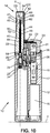
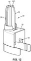
- FIGS 9 , 10 , 11 and 12 illustrate a second embodiment of a utility lighter 10 according to the invention.
- the rigid support 44 and the cover 35 are formed in a sole molded piece 33.
- This molded piece 33 shown in figure 12 , is molded in an electrically insulating thermoplastic resin.
- Such a molded piece 33 has the advantage of reducing the number of pieces required, since the cover 35 and the rigid support 44 are the same piece.
- such an embodiment improves the insulation of the electrical circuit by avoiding short-circuit through the cover 35.
- the cover 35 could create a failure in the ignition.
- the cover is made of an electrically insulating thermoplastic resin, there is no more risk of any short-circuit. Besides, this feature protects the user of a possible electrical discharge in his fingers.
- the molded piece 33 comprises two protrusions 39, which allows it to be snap-fitted to the body 17 of the pocket lighter 12. When snap-fitted, this connection between the molded piece 33 and the body 17 is not removable.
- Figure 9 illustrates only one protrusion 39, the other protrusion 39 being hidden by the cover.
- This second embodiment provides another advantage that consists on a greater precision of positioning of this molded piece 33 with respect to the pocket lighter 12 and therefore to the jet 24.
- the achievement of a good sealing between the upper part 26 of the jet 24 and the cylindrical seal 40 is facilitate.
- the present invention further concerns a method for manufacturing a flame producing assembly.
- the method consists first to provide the sub-unit assembly 14.
- the helical spring 46 is inserted inside the rigid support 42.
- this set is snap-fitted inside the extended wand 42, forming therefore the sub-unit assembly 14.
- the sub-unit assembly 14 according to the first embodiment is snap-fitted on the cover 35 of the pocket lighter 12, the cover 35 being previously attached to the body 17 of the pocket lighter 12.
- the sub-unit assembly is snap-fitted directly on the body 17 of the pocket lighter 12. In this way, according to either the first or the second embodiment, the sub-unit assembly 14 is fixedly attached to the pocket lighter 12.
- Such an assembly has the advantage to be easily implemented.
- the assembly of the utility lighter 10 according to the second embodiment has the advantage to be easier assembled than the utility lighter 10 according to the first embodiment, the preliminary fixing step of the cover 35 on the body 17 not being required. An assembly on an automatic machine for producing several flames producing assembly is therefore achievable.
Landscapes
- Engineering & Computer Science (AREA)
- Chemical & Material Sciences (AREA)
- Combustion & Propulsion (AREA)
- Mechanical Engineering (AREA)
- General Engineering & Computer Science (AREA)
- Lighters Containing Fuel (AREA)
- Air Bags (AREA)
Priority Applications (1)
| Application Number | Priority Date | Filing Date | Title |
|---|---|---|---|
| EP21192134.1A EP3929486A1 (fr) | 2016-12-13 | 2016-12-13 | Ensemble de production de flammes |
Applications Claiming Priority (3)
| Application Number | Priority Date | Filing Date | Title |
|---|---|---|---|
| PCT/EP2016/080851 WO2018108254A1 (fr) | 2016-12-13 | 2016-12-13 | Ensemble de production de flammes et procédé permettant de fabriquer un tel ensemble de production de flammes |
| EP16810364.6A EP3555528B1 (fr) | 2016-12-13 | 2016-12-13 | Ensemble de production de flammes et procédé permettant de fabriquer un tel ensemble de production de flammes |
| EP21192134.1A EP3929486A1 (fr) | 2016-12-13 | 2016-12-13 | Ensemble de production de flammes |
Related Parent Applications (2)
| Application Number | Title | Priority Date | Filing Date |
|---|---|---|---|
| EP16810364.6A Division EP3555528B1 (fr) | 2016-12-13 | 2016-12-13 | Ensemble de production de flammes et procédé permettant de fabriquer un tel ensemble de production de flammes |
| EP16810364.6A Division-Into EP3555528B1 (fr) | 2016-12-13 | 2016-12-13 | Ensemble de production de flammes et procédé permettant de fabriquer un tel ensemble de production de flammes |
Publications (1)
| Publication Number | Publication Date |
|---|---|
| EP3929486A1 true EP3929486A1 (fr) | 2021-12-29 |
Family
ID=57544441
Family Applications (2)
| Application Number | Title | Priority Date | Filing Date |
|---|---|---|---|
| EP21192134.1A Pending EP3929486A1 (fr) | 2016-12-13 | 2016-12-13 | Ensemble de production de flammes |
| EP16810364.6A Active EP3555528B1 (fr) | 2016-12-13 | 2016-12-13 | Ensemble de production de flammes et procédé permettant de fabriquer un tel ensemble de production de flammes |
Family Applications After (1)
| Application Number | Title | Priority Date | Filing Date |
|---|---|---|---|
| EP16810364.6A Active EP3555528B1 (fr) | 2016-12-13 | 2016-12-13 | Ensemble de production de flammes et procédé permettant de fabriquer un tel ensemble de production de flammes |
Country Status (10)
| Country | Link |
|---|---|
| US (2) | US11549685B2 (fr) |
| EP (2) | EP3929486A1 (fr) |
| CN (2) | CN112902222B (fr) |
| AR (1) | AR110358A1 (fr) |
| BR (1) | BR112019010259B1 (fr) |
| CA (1) | CA3046039C (fr) |
| ES (1) | ES2896895T3 (fr) |
| MX (1) | MX2019006857A (fr) |
| RU (1) | RU2718374C1 (fr) |
| WO (1) | WO2018108254A1 (fr) |
Families Citing this family (3)
| Publication number | Priority date | Publication date | Assignee | Title |
|---|---|---|---|---|
| US11112112B2 (en) * | 2016-12-13 | 2021-09-07 | Societe Bic | Flame producing assembly and method for manufacturing such a flame producing assembly |
| WO2021056319A1 (fr) * | 2019-09-26 | 2021-04-01 | 赣州市卫诚火机制造有限公司 | Allumeur |
| USD970802S1 (en) * | 2021-05-21 | 2022-11-22 | Knnox Pty Ltd | Apparatus for lighting fires |
Citations (6)
| Publication number | Priority date | Publication date | Assignee | Title |
|---|---|---|---|---|
| US4778380A (en) * | 1986-09-11 | 1988-10-18 | Tokai Corporation | Rod-shaped gas igniter |
| EP0446162B1 (fr) | 1990-02-28 | 1992-11-11 | Flamagas S.A. | Briquet à gaz liquefié pour la cuisine |
| US5865614A (en) * | 1997-01-10 | 1999-02-02 | Huang-His Hsu | Electronic ignition gun |
| US5980242A (en) * | 1997-09-25 | 1999-11-09 | Man; Aman Chung Kai | Child resistant barbecue and fireplace lighter |
| US20050053881A1 (en) * | 2000-11-03 | 2005-03-10 | Bic Corporation | Multi-mode lighter |
| US20060281039A1 (en) * | 2005-06-09 | 2006-12-14 | Luo Xin W | Lighter |
Family Cites Families (27)
| Publication number | Priority date | Publication date | Assignee | Title |
|---|---|---|---|---|
| US2638925A (en) * | 1949-03-23 | 1953-05-19 | Utah Oil Refining Company | Helical spring valve |
| DE1429117A1 (fr) * | 1963-06-01 | 1970-07-09 | ||
| US4424018A (en) * | 1981-09-14 | 1984-01-03 | Lowther Sr Roy E | Flexible firelighter |
| CN1161426A (zh) * | 1995-09-28 | 1997-10-08 | 株式会社东海 | 催化剂支撑件 |
| DE69836731T2 (de) * | 1997-01-22 | 2007-10-11 | Bic Corp., Milford | Allzweckfeuerzeug |
| JPH10332147A (ja) * | 1997-05-28 | 1998-12-15 | Nippon Baindaa Kogyo Kk | ガスライター |
| CN2373696Y (zh) * | 1999-04-19 | 2000-04-12 | 崔建新 | 连续电子脉冲间接点火式打火总成 |
| US6428309B1 (en) * | 2000-02-22 | 2002-08-06 | Bic Corporation | Utility lighter |
| US6336807B1 (en) * | 2000-09-29 | 2002-01-08 | Huang-Hsi Hsu | Gas lighter with dual safety mechanism |
| US6648630B2 (en) * | 2000-11-30 | 2003-11-18 | Robert W. Tse | Gas igniter with flexible extension |
| US6478575B2 (en) * | 2001-02-12 | 2002-11-12 | Polycity Enterprise Limited | Lighter |
| JP2003176899A (ja) * | 2001-12-11 | 2003-06-27 | Tokai Corp | 樹脂製燃料圧力容器 |
| CN1435595A (zh) * | 2002-12-12 | 2003-08-13 | 张颖 | 压电点火装置 |
| CN1441197A (zh) * | 2003-01-08 | 2003-09-10 | 张颖 | 安全打火机 |
| CN1912469A (zh) * | 2005-08-08 | 2007-02-14 | 刘歌群 | 便携式远距离点火打火机 |
| JP2007240068A (ja) * | 2006-03-09 | 2007-09-20 | Tokai Corp | ガスライター |
| CN101290140A (zh) * | 2007-04-20 | 2008-10-22 | 汪祥卫 | 一种打火机 |
| CN101140076B (zh) * | 2007-09-20 | 2012-01-11 | 黄逢竞 | 一种可调节打火机 |
| KR101630196B1 (ko) * | 2009-01-12 | 2016-06-14 | 페더럴-모굴 이그니션 컴퍼니 | 공기/연료 혼합물용 플렉시블 점화기 어셈블리 및 그 구성 방법 |
| FR2946731B1 (fr) * | 2009-06-11 | 2011-07-22 | Bic Soc | Briquet a allumage piezo-electrique. |
| CN201476049U (zh) * | 2009-07-24 | 2010-05-19 | 厦门王氏明发打火机有限公司 | 便携式打火机 |
| JP2012037214A (ja) * | 2010-08-09 | 2012-02-23 | Kowa Seisakusho:Kk | ライターの安全装置 |
| BR112013014191B1 (pt) * | 2010-12-09 | 2020-01-07 | SOCIéTé BIC | Conjunto de válvula e acendedor a gás |
| CN103148510B (zh) * | 2013-03-25 | 2015-08-19 | 宁波新海电气股份有限公司 | 一种无线压电打火机 |
| US9556964B2 (en) * | 2014-04-22 | 2017-01-31 | Nws Europa Gmbh | Gravity drain valve |
| CN204629557U (zh) * | 2015-05-13 | 2015-09-09 | 慈溪市艾丽格电子有限公司 | 一种小型取火装置 |
| US9848579B2 (en) * | 2015-02-20 | 2017-12-26 | Marirose Charlene Lynch | System for holding and drying tennis and other balls, and dog toy |
-
2016
- 2016-12-13 ES ES16810364T patent/ES2896895T3/es active Active
- 2016-12-13 EP EP21192134.1A patent/EP3929486A1/fr active Pending
- 2016-12-13 CN CN202110276537.0A patent/CN112902222B/zh active Active
- 2016-12-13 US US16/468,339 patent/US11549685B2/en active Active
- 2016-12-13 BR BR112019010259-0A patent/BR112019010259B1/pt active IP Right Grant
- 2016-12-13 EP EP16810364.6A patent/EP3555528B1/fr active Active
- 2016-12-13 MX MX2019006857A patent/MX2019006857A/es unknown
- 2016-12-13 RU RU2019121538A patent/RU2718374C1/ru active
- 2016-12-13 CA CA3046039A patent/CA3046039C/fr active Active
- 2016-12-13 CN CN201680092084.3A patent/CN110268194B/zh active Active
- 2016-12-13 WO PCT/EP2016/080851 patent/WO2018108254A1/fr unknown
-
2017
- 2017-12-13 AR ARP170103489A patent/AR110358A1/es unknown
-
2020
- 2020-07-07 US US16/922,376 patent/US10845054B1/en active Active
Patent Citations (6)
| Publication number | Priority date | Publication date | Assignee | Title |
|---|---|---|---|---|
| US4778380A (en) * | 1986-09-11 | 1988-10-18 | Tokai Corporation | Rod-shaped gas igniter |
| EP0446162B1 (fr) | 1990-02-28 | 1992-11-11 | Flamagas S.A. | Briquet à gaz liquefié pour la cuisine |
| US5865614A (en) * | 1997-01-10 | 1999-02-02 | Huang-His Hsu | Electronic ignition gun |
| US5980242A (en) * | 1997-09-25 | 1999-11-09 | Man; Aman Chung Kai | Child resistant barbecue and fireplace lighter |
| US20050053881A1 (en) * | 2000-11-03 | 2005-03-10 | Bic Corporation | Multi-mode lighter |
| US20060281039A1 (en) * | 2005-06-09 | 2006-12-14 | Luo Xin W | Lighter |
Also Published As
| Publication number | Publication date |
|---|---|
| CN112902222B (zh) | 2022-08-26 |
| BR112019010259A2 (pt) | 2019-09-03 |
| AR110358A1 (es) | 2019-03-20 |
| WO2018108254A1 (fr) | 2018-06-21 |
| CN110268194A (zh) | 2019-09-20 |
| US11549685B2 (en) | 2023-01-10 |
| CA3046039A1 (fr) | 2018-06-21 |
| US20200292171A1 (en) | 2020-09-17 |
| EP3555528B1 (fr) | 2021-09-29 |
| CN110268194B (zh) | 2021-03-30 |
| US10845054B1 (en) | 2020-11-24 |
| EP3555528A1 (fr) | 2019-10-23 |
| CA3046039C (fr) | 2023-08-08 |
| MX2019006857A (es) | 2019-08-01 |
| RU2718374C1 (ru) | 2020-04-02 |
| ES2896895T3 (es) | 2022-02-28 |
| CN112902222A (zh) | 2021-06-04 |
| US20200348022A1 (en) | 2020-11-05 |
| BR112019010259B1 (pt) | 2022-11-16 |
Similar Documents
| Publication | Publication Date | Title |
|---|---|---|
| US10845054B1 (en) | Flame producing assembly and method for manufacturing such a flame producing assembly | |
| CN106196166B (zh) | 手持式电子点烟工具 | |
| CN103363544B (zh) | 一种电弧点烟器 | |
| US20230119487A1 (en) | Flame producing assembly and method for manufacturing such a flame producing assembly | |
| CN103851644B (zh) | 一种电弧点烟器 | |
| CN203442879U (zh) | 一种电弧点烟器 | |
| EP0273302A2 (fr) | Allumeur de pipes du type piézoélectrique | |
| CN207282560U (zh) | 电池组件及其电子烟 | |
| CN203757763U (zh) | 一种电弧点烟器 | |
| WO2001063179A1 (fr) | Allumeur domestique | |
| AU2001238601A1 (en) | Utility lighter | |
| US3437880A (en) | Electric gas ignitor | |
| US1826576A (en) | Lighter fob | |
| US10800309B2 (en) | Car cigarette lighter | |
| US3419705A (en) | Heater filament for an electrical cigarette lighter | |
| CN214840964U (zh) | 一种便于组装的打火机 | |
| CN103982915B (zh) | 一种电弧点烟器 | |
| CN203837020U (zh) | 一种电弧点烟器 | |
| US2982839A (en) | Electric cigarette lighters | |
| CN205505069U (zh) | 一种明火机与点烟器结合的打火机 | |
| CN1387804A (zh) | 香烟点燃器 | |
| CN103868097A (zh) | 一种点烟器的电弧发生装置 | |
| JPH0311566Y2 (fr) | ||
| JPS6210597Y2 (fr) | ||
| CN111271740A (zh) | 一种高稳定性燃气点火装置 |
Legal Events
| Date | Code | Title | Description |
|---|---|---|---|
| PUAI | Public reference made under article 153(3) epc to a published international application that has entered the european phase |
Free format text: ORIGINAL CODE: 0009012 |
|
| STAA | Information on the status of an ep patent application or granted ep patent |
Free format text: STATUS: THE APPLICATION HAS BEEN PUBLISHED |
|
| AC | Divisional application: reference to earlier application |
Ref document number: 3555528 Country of ref document: EP Kind code of ref document: P |
|
| AK | Designated contracting states |
Kind code of ref document: A1 Designated state(s): AL AT BE BG CH CY CZ DE DK EE ES FI FR GB GR HR HU IE IS IT LI LT LU LV MC MK MT NL NO PL PT RO RS SE SI SK SM TR |
|
| B565 | Issuance of search results under rule 164(2) epc |
Effective date: 20211116 |
|
| STAA | Information on the status of an ep patent application or granted ep patent |
Free format text: STATUS: REQUEST FOR EXAMINATION WAS MADE |
|
| 17P | Request for examination filed |
Effective date: 20220628 |
|
| RBV | Designated contracting states (corrected) |
Designated state(s): AL AT BE BG CH CY CZ DE DK EE ES FI FR GB GR HR HU IE IS IT LI LT LU LV MC MK MT NL NO PL PT RO RS SE SI SK SM TR |
|
| RAP3 | Party data changed (applicant data changed or rights of an application transferred) |
Owner name: SOCIETE BIC |