EP3929417A1 - Sub-chamber type engine - Google Patents
Sub-chamber type engine Download PDFInfo
- Publication number
- EP3929417A1 EP3929417A1 EP19926426.8A EP19926426A EP3929417A1 EP 3929417 A1 EP3929417 A1 EP 3929417A1 EP 19926426 A EP19926426 A EP 19926426A EP 3929417 A1 EP3929417 A1 EP 3929417A1
- Authority
- EP
- European Patent Office
- Prior art keywords
- precombustion chamber
- chamber cap
- cap
- holder
- holding member
- Prior art date
- Legal status (The legal status is an assumption and is not a legal conclusion. Google has not performed a legal analysis and makes no representation as to the accuracy of the status listed.)
- Withdrawn
Links
Images




Classifications
-
- F—MECHANICAL ENGINEERING; LIGHTING; HEATING; WEAPONS; BLASTING
- F02—COMBUSTION ENGINES; HOT-GAS OR COMBUSTION-PRODUCT ENGINE PLANTS
- F02B—INTERNAL-COMBUSTION PISTON ENGINES; COMBUSTION ENGINES IN GENERAL
- F02B19/00—Engines characterised by precombustion chambers
- F02B19/16—Chamber shapes or constructions not specific to sub-groups F02B19/02 - F02B19/10
-
- F—MECHANICAL ENGINEERING; LIGHTING; HEATING; WEAPONS; BLASTING
- F02—COMBUSTION ENGINES; HOT-GAS OR COMBUSTION-PRODUCT ENGINE PLANTS
- F02B—INTERNAL-COMBUSTION PISTON ENGINES; COMBUSTION ENGINES IN GENERAL
- F02B19/00—Engines characterised by precombustion chambers
- F02B19/10—Engines characterised by precombustion chambers with fuel introduced partly into pre-combustion chamber, and partly into cylinder
- F02B19/1004—Engines characterised by precombustion chambers with fuel introduced partly into pre-combustion chamber, and partly into cylinder details of combustion chamber, e.g. mounting arrangements
-
- F—MECHANICAL ENGINEERING; LIGHTING; HEATING; WEAPONS; BLASTING
- F02—COMBUSTION ENGINES; HOT-GAS OR COMBUSTION-PRODUCT ENGINE PLANTS
- F02B—INTERNAL-COMBUSTION PISTON ENGINES; COMBUSTION ENGINES IN GENERAL
- F02B19/00—Engines characterised by precombustion chambers
- F02B19/12—Engines characterised by precombustion chambers with positive ignition
-
- F—MECHANICAL ENGINEERING; LIGHTING; HEATING; WEAPONS; BLASTING
- F02—COMBUSTION ENGINES; HOT-GAS OR COMBUSTION-PRODUCT ENGINE PLANTS
- F02M—SUPPLYING COMBUSTION ENGINES IN GENERAL WITH COMBUSTIBLE MIXTURES OR CONSTITUENTS THEREOF
- F02M21/00—Apparatus for supplying engines with non-liquid fuels, e.g. gaseous fuels stored in liquid form
- F02M21/02—Apparatus for supplying engines with non-liquid fuels, e.g. gaseous fuels stored in liquid form for gaseous fuels
- F02M21/0218—Details on the gaseous fuel supply system, e.g. tanks, valves, pipes, pumps, rails, injectors or mixers
- F02M21/0248—Injectors
- F02M21/0275—Injectors for in-cylinder direct injection, e.g. injector combined with spark plug
-
- Y—GENERAL TAGGING OF NEW TECHNOLOGICAL DEVELOPMENTS; GENERAL TAGGING OF CROSS-SECTIONAL TECHNOLOGIES SPANNING OVER SEVERAL SECTIONS OF THE IPC; TECHNICAL SUBJECTS COVERED BY FORMER USPC CROSS-REFERENCE ART COLLECTIONS [XRACs] AND DIGESTS
- Y02—TECHNOLOGIES OR APPLICATIONS FOR MITIGATION OR ADAPTATION AGAINST CLIMATE CHANGE
- Y02T—CLIMATE CHANGE MITIGATION TECHNOLOGIES RELATED TO TRANSPORTATION
- Y02T10/00—Road transport of goods or passengers
- Y02T10/10—Internal combustion engine [ICE] based vehicles
- Y02T10/12—Improving ICE efficiencies
-
- Y—GENERAL TAGGING OF NEW TECHNOLOGICAL DEVELOPMENTS; GENERAL TAGGING OF CROSS-SECTIONAL TECHNOLOGIES SPANNING OVER SEVERAL SECTIONS OF THE IPC; TECHNICAL SUBJECTS COVERED BY FORMER USPC CROSS-REFERENCE ART COLLECTIONS [XRACs] AND DIGESTS
- Y02—TECHNOLOGIES OR APPLICATIONS FOR MITIGATION OR ADAPTATION AGAINST CLIMATE CHANGE
- Y02T—CLIMATE CHANGE MITIGATION TECHNOLOGIES RELATED TO TRANSPORTATION
- Y02T10/00—Road transport of goods or passengers
- Y02T10/10—Internal combustion engine [ICE] based vehicles
- Y02T10/30—Use of alternative fuels, e.g. biofuels
Definitions
- the present disclosure relates to a precombustion chamber engine.
- a precombustion chamber engine is known as a type of engine that has a precombustion chamber for ignition in a cylinder head.
- a precombustion chamber gas engine is known as a type of precombustion chamber engine that is operated by combustion of gaseous fuel (fuel gas).
- fuel gas gaseous fuel
- a precombustion-chamber forming portion that forms the precombustion chamber includes a cap (precombustion chamber cap) for supplying a flame to the main combustion chamber and a precombustion chamber holder for holding the cap.
- the fuel gas in the main combustion chamber When the fuel gas in the main combustion chamber is compressed by a piston, the fuel gas in the precombustion chamber is ignited by an ignition plug installed in the precombustion chamber to generate a flame, and the flame is injected through the cap into the main combustion chamber to ignite the air-fuel mixture in the main combustion chamber, and the combustion operation of the precombustion chamber gas engine is performed.
- Patent Document 1 discloses a configuration where the precombustion chamber cap is held by the precombustion chamber holder by applying a pressing force to the precombustion chamber cap using a fastening member such as a bolt from a direction crossing the central axis of the precombustion chamber cap to press the cap against the inner wall of the precombustion chamber holder.
- Patent Document 1 JP2015-117582
- an object of at least one embodiment of the present invention is to provide a precombustion chamber engine with improved ease of assembly.
- a precombustion chamber gas engine comprises: a cylinder head defining a main combustion chamber together with a cylinder liner and a piston top surface; a precombustion chamber cap mounted on the cylinder head by inserting a distal end portion of the precombustion chamber cap into an insertion hole formed in the cylinder head; a precombustion chamber holder disposed inside the cylinder head; and a precombustion chamber cap holding member fixed to the precombustion chamber holder and configured to suspend and support the precombustion chamber cap.
- the precombustion chamber cap includes a reduced diameter portion with a diameter decreasing from a proximal end portion of the precombustion chamber cap to an intermediate portion that has a smaller diameter than the proximal end portion.
- the precombustion chamber cap holding member is configured to lock the reduced diameter portion and to have a gap between the precombustion chamber cap holding member and the proximal end portion when the precombustion chamber cap holding member suspends and supports the precombustion chamber cap.
- the central axes of the precombustion chamber holder and the insertion hole in the cylinder head of the precombustion chamber engine may be displaced from each other in a direction crossing the central axis of the precombustion chamber cap (e.g., horizontal direction).
- the precombustion chamber cap is suspended and supported while the reduced diameter portion of the precombustion chamber cap is locked by the precombustion chamber cap holding member fixed to the precombustion chamber holder, and a gap is secured between the precombustion chamber cap holding member and the proximal end portion of the precombustion chamber cap.
- the positioning of the precombustion chamber cap can be easily performed while absorbing the positional displacement of the central axes of the precombustion chamber holder and the insertion hole, so that it is possible to provide the precombustion chamber engine with improved ease of assembly.
- the precombustion chamber cap holding member may include: a cylindrical large diameter portion fixed to the precombustion chamber holder; and a holding portion connected to the large diameter portion and disposed below the large diameter portion.
- the holding portion has a distal end disposed closer to a central axis of the precombustion chamber cap than an outer peripheral surface of the proximal end portion is.
- the reduced diameter portion of the precombustion chamber cap is locked by the distal end of the holding portion disposed closer to the central axis of the precombustion chamber cap than the outer peripheral surface of the proximal end portion of the precombustion chamber cap is.
- the precombustion chamber holder may include a male threaded portion formed on an outer periphery of the precombustion chamber holder.
- the precombustion chamber cap holding member may include a female threaded portion formed on an inner periphery of the large diameter portion of the precombustion chamber cap holding member to be engaged with the male threaded portion.
- the precombustion chamber cap can be held by the precombustion chamber holder.
- the holding portion may include a tapered portion formed so as to be closer to the central axis with an increase in distance from the large diameter portion along a direction of the central axis.
- the holding portion may include an inner flange portion protruding inward from a lower end of the large diameter portion so as to cross a direction of the central axis.
- the proximal end portion of the precombustion chamber cap may have a smaller diameter than the precombustion chamber holder.
- the precombustion chamber cap having a smaller diameter than the precombustion chamber holder i.e., a different diameter from the precombustion chamber holder, can be smoothly held by the precombustion chamber holder.
- the precombustion chamber engine that is flexible to differences in dimension in the radial direction of the precombustion chamber cap.
- the precombustion chamber engine may further comprise a seal member interposed between the precombustion chamber holder and the proximal end portion of the precombustion chamber cap or between a lower end surface of the intermediate portion of the precombustion chamber cap and the cylinder head.
- the sealing performance between the precombustion chamber holder and the precombustion chamber cap can be improved compared to the case where the seal member is not interposed between the precombustion chamber holder and the precombustion chamber cap, so that it is possible to prevent fuel from leaking through a gap between the precombustion chamber cap and the precombustion chamber holder, for example.
- the precombustion chamber holder may include a first recess on a surface facing the precombustion chamber cap.
- the precombustion chamber cap may include a second recess on a surface facing the precombustion chamber holder.
- the precombustion chamber engine may be configured such that a pin member is fitted in the first recess and the second recess.
- the precombustion chamber engine may further comprise a fuel gas supply section for supplying gaseous fuel into the main combustion chamber.
- the precombustion chamber cap holding member may include a clamp for fastening the precombustion chamber holder with the precombustion chamber cap.
- the precombustion chamber holder may be connected to the precombustion chamber cap holding member by being press-fitted in the large diameter portion of the precombustion chamber cap holding member.
- At least one embodiment of the present invention provides a precombustion chamber engine with improved ease of assembly.
- an expression of relative or absolute arrangement such as “in a direction”, “along a direction”, “parallel”, “orthogonal”, “centered”, “concentric” and “coaxial” shall not be construed as indicating only the arrangement in a strict literal sense, but also includes a state where the arrangement is relatively displaced by a tolerance, or by an angle or a distance whereby it is possible to achieve the same function.
- an expression of an equal state such as “same” “equal” and “uniform” shall not be construed as indicating only the state in which the feature is strictly equal, but also includes a state in which there is a tolerance or a difference that can still achieve the same function.
- an expression of a shape such as a rectangular shape or a cylindrical shape shall not be construed as only the geometrically strict shape, but also includes a shape with unevenness or chamfered corners within the range in which the same effect can be achieved.
- FIG. 1 is a longitudinal cross-sectional view showing a configuration example of a precombustion chamber engine according to an embodiment of the present disclosure.
- FIG. 2 is a schematic diagram showing a configuration example of a precombustion chamber cap holding member according to an embodiment.
- a precombustion chamber engine 1 includes a cylinder head 23 defining a main combustion chamber 4 (main chamber) together with a cylinder liner 22 and a piston top surface 3A, a precombustion chamber cap 10 mounted on the cylinder head 23 by inserting a distal end portion 15 into an insertion hole 23A formed in the cylinder head 23, a precombustion chamber holder 40 disposed inside the cylinder head 23, and a precombustion chamber cap holding member 30 fixed to the precombustion chamber holder 40 and configured to suspend and support the precombustion chamber cap 10.
- the precombustion chamber engine 1 further includes, in addition to the above-described components, an intake port 5 disposed on the cylinder head 23, an intake valve 5A for opening and closing the intake port 5, an exhaust port 6 disposed on the cylinder head 23, and an exhaust valve 6A for opening and closing the exhaust port 6, for example.
- the cylinder head 23 has a precombustion chamber 11 (auxiliary chamber), and the main combustion chamber 4 and the precombustion chamber 11 are communicated through at least one injection port 16 (injection hole).
- the precombustion chamber 11 is connected to an ignition fuel supply passage 18 for introducing ignition fuel (e.g., fuel gas) to the precombustion chamber 11. Further, the precombustion chamber 11 is equipped with an ignition plug 19 to ignite the air-fuel mixture containing the ignition fuel introduced into the precombustion chamber 11. Combustion gas generated in the precombustion chamber 11 is injected as a torch through the injection port 16 shown in FIG. 1 to combust the mixed gas in the main combustion chamber 4.
- ignition fuel e.g., fuel gas
- the precombustion chamber cap 10 includes a reduced diameter portion 13 with a diameter decreasing from the proximal end portion 12 of the precombustion chamber cap 10 to an intermediate portion 14 that has a smaller diameter than the proximal end portion 12.
- the precombustion chamber cap 10 includes a proximal end portion 12 (large diameter portion) with an upper end surface 10A facing the precombustion chamber holder 40, an intermediate portion 14 disposed farther from the precombustion chamber holder 40 than the proximal end portion 12 in the direction of the central axis C and having a smaller diameter than the proximal end portion 12, a reduced diameter portion 13 disposed between the proximal end portion 12 and the intermediate portion 14 and connecting the outer peripheral edge of the proximal end portion 12 to the outer peripheral edge of the intermediate portion 14 in a smooth and continuous manner, and a distal end portion 15 having a smaller diameter than the intermediate portion 14.
- the distal end portion 15 of the precombustion chamber cap 10 has at least one injection hole 16.
- the lower end portion of the precombustion chamber holder 40 may have substantially the same diameter as the upper portion (proximal end portion 12) of the precombustion chamber cap 10.
- the precombustion chamber cap holding member 30 is configured to lock the reduced diameter portion 13 and to have a gap between the precombustion chamber cap holding member 30 and the proximal end portion 12 when suspending and supporting the precombustion chamber cap 10.
- a gap G is formed between an inner peripheral surface 30A of the large diameter portion 32 of the precombustion chamber cap holding member 30 and an outer peripheral surface 12A of the proximal end portion 12 of the precombustion chamber cap 10.
- the central axes C of the precombustion chamber holder 40 and the insertion hole 23A in the cylinder head 23 of the precombustion chamber engine 1 may be displaced from each other in a direction crossing the central axis C of the precombustion chamber cap 10 (e.g., horizontal direction).
- the positioning of the precombustion chamber cap 10 can be easily performed while absorbing the positional displacement of the central axes C of the precombustion chamber holder 40 and the insertion hole 23A, so that it is possible to provide the precombustion chamber engine 1 with improved ease of assembly.
- the precombustion chamber cap is held by the precombustion chamber holder by pressing the fastening member such as a bolt from the side of the precombustion chamber cap, it is difficult to adjust the position of the precombustion chamber cap by the bolt screwed from the side, but in the configuration of the present disclosure, it is easy to adjust the position of the precombustion chamber cap.
- the precombustion chamber engine 1 may further include a fuel gas supply section 70 for supplying gaseous fuel (fuel gas) into the main combustion chamber 4 (see FIG. 1 ).
- the precombustion chamber engine 1 is configured as a precombustion chamber gas engine.
- the gaseous fuel may include natural gas or city gas, for example.
- a mixture of fuel gas and air is supplied to the main combustion chamber 4 in the cylinder head 23, and fuel gas is supplied to the precombustion chamber 11.
- the fuel gas supplied to the precombustion chamber 11 is ignited by the ignition plug 19 disposed in the precombustion chamber 11 to generate a flame from the precombustion chamber 11, and the flame is injected through the injection port 16 of the precombustion chamber cap 10 into the main combustion chamber 4.
- Precombustion chamber gas engines are widely used in power generation engines for emergency and non-emergency use, engines for construction machinery, and engines installed in ships and trains, etc., because of their high efficiency and high output.
- a seal member 50 (including a gasket, for example) is interposed between the precombustion chamber holder 40 and the proximal end portion 12 of the precombustion chamber cap 10 or between a lower end surface 14A (step portion) of the intermediate portion 14 of the precombustion chamber cap 10 and the cylinder head 23.
- the sealing performance between the precombustion chamber holder 40 and the precombustion chamber cap 10 can be improved compared to the case where the seal member 50 is not interposed between the precombustion chamber holder 40 and the precombustion chamber cap 10, so that it is possible to prevent fuel from leaking through a gap between the precombustion chamber cap 10 and the precombustion chamber holder 40, for example.
- the precombustion chamber cap 10 is held by the precombustion chamber holder 40 by applying a pressing force to the precombustion chamber cap 10 to press the cap against the inner wall of the precombustion chamber holder 40 from a direction crossing the central axis C of the precombustion chamber cap 10, it cannot be said that a sufficient pressing force can be applied in the direction of the central axis C (e.g., vertical direction), and there is room for further improvement, but in the precombustion chamber engine 1 of the present disclosure having the above configuration, since the sealing performance between the precombustion chamber cap 10 and the precombustion chamber holder 40 can be improved, the leakage of fuel through a gap between the precombustion chamber cap 10 and the precombustion chamber holder 40 can be reduced.
- the precombustion chamber holder 40 may include a first recess 43 on the lower end surface 40A facing the precombustion chamber cap 10.
- the precombustion chamber cap 10 may include a second recess 17 on the upper end surface 10A facing the precombustion chamber holder 40.
- a pin member 60 may be fitted in the first recess 43 and the second recess 17 (see FIG. 1 ).
- the precombustion chamber cap holding member 30 may include a cylindrical large diameter portion 32 fixed to the precombustion chamber holder 40, and a holding portion 34 connected to the large diameter portion 32 and disposed below the large diameter portion 32, with a distal end disposed closer to the central axis C of the precombustion chamber cap 10 than the outer peripheral surface 12A of the proximal end portion 12.
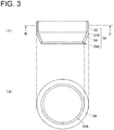
- the holding portion 34 may be formed in an annular shape for example as illustrated in part (A) of FIG. 3 , part (B) of FIG. 3 , part (A) of FIG. 4 , and part (B) of FIG. 4 .
- the holding portion 34 may be formed in a claw or hook shape for example as illustrated in part (A) of FIG. 5 , part (B) of FIG. 5 , part (A) of FIG. 6 , and part (B) of FIG. 6 .
- the reduced diameter portion 13 of the precombustion chamber cap 10 is locked by the distal end 34A of the holding portion 34 disposed closer to the central axis C of the precombustion chamber cap 10 than the outer peripheral surface 12A of the proximal end portion 12 of the precombustion chamber cap 10.
- the precombustion chamber holder 40 may include a male threaded portion 41 formed on an outer periphery of the precombustion chamber holder 40.
- the precombustion chamber cap holding member 30 may include a female threaded portion 31 formed on an inner peripheral surface 32A of the large diameter portion 32 of the precombustion chamber cap holding member 30 to be engaged with the male threaded portion 41.
- the precombustion chamber cap 10 can be held by the precombustion chamber holder 40.
- the holding portion 34 may include a tapered portion 34B formed so as to be closer to the central axis C with an increase in distance from the large diameter portion 32 along the direction of the central axis C (for example, see part (A) of FIG. 3 , part (B) of FIG. 3 , part (A) of FIG. 5 , and part (B) of FIG. 5 ).
- the precombustion chamber cap 10 can be easily aligned, so that it is possible to provide the precombustion chamber engine 1 with improved ease of assembly.
- the holding portion 34 may include an inner flange portion 34C (flange portion) protruding inward from a lower end 32B of the large diameter portion 32 so as to cross the direction of the central axis C.
- the proximal end portion 12 of the precombustion chamber cap 10 may have a smaller diameter than the precombustion chamber holder 40.
- the precombustion chamber cap 10 and the precombustion chamber holder 40 are fastened via the precombustion chamber cap holding member 30, the precombustion chamber cap 10 having a smaller diameter than the precombustion chamber holder 40, i.e., a different diameter from the precombustion chamber holder 40, can be smoothly held by the precombustion chamber holder 40.
- the precombustion chamber engine 1 that is flexible to differences in dimension in the radial direction of the precombustion chamber cap 10.
- the precombustion chamber holder 40 may be connected to the precombustion chamber cap holding member 30 by being press-fitted in the large diameter portion 32 of the precombustion chamber cap holding member 30.
- the precombustion chamber cap holding member 30 may include a clamp 80 for fastening the precombustion chamber holder 40 with the precombustion chamber cap 10.
- At least one embodiment of the present invention provides a precombustion chamber engine with improved ease of assembly.
Landscapes
- Engineering & Computer Science (AREA)
- Chemical & Material Sciences (AREA)
- Combustion & Propulsion (AREA)
- Mechanical Engineering (AREA)
- General Engineering & Computer Science (AREA)
- Chemical Kinetics & Catalysis (AREA)
- General Chemical & Material Sciences (AREA)
- Oil, Petroleum & Natural Gas (AREA)
- Combustion Methods Of Internal-Combustion Engines (AREA)
Abstract
Description
- The present disclosure relates to a precombustion chamber engine.
- Conventionally, a precombustion chamber engine is known as a type of engine that has a precombustion chamber for ignition in a cylinder head. Further, a precombustion chamber gas engine is known as a type of precombustion chamber engine that is operated by combustion of gaseous fuel (fuel gas). In the precombustion chamber gas engine, a mixture of fuel gas and air is supplied to the main combustion chamber in the cylinder head, and fuel gas is supplied to the precombustion chamber. A precombustion-chamber forming portion that forms the precombustion chamber includes a cap (precombustion chamber cap) for supplying a flame to the main combustion chamber and a precombustion chamber holder for holding the cap. When the fuel gas in the main combustion chamber is compressed by a piston, the fuel gas in the precombustion chamber is ignited by an ignition plug installed in the precombustion chamber to generate a flame, and the flame is injected through the cap into the main combustion chamber to ignite the air-fuel mixture in the main combustion chamber, and the combustion operation of the precombustion chamber gas engine is performed.
- Regarding the precombustion chamber engine, for example,
Patent Document 1 discloses a configuration where the precombustion chamber cap is held by the precombustion chamber holder by applying a pressing force to the precombustion chamber cap using a fastening member such as a bolt from a direction crossing the central axis of the precombustion chamber cap to press the cap against the inner wall of the precombustion chamber holder. - Patent Document 1:
JP2015-117582 - However, in the configuration where the precombustion chamber cap is held by the precombustion chamber holder by the fastening force applied from the side as in the precombustion chamber engine of
Patent Document 1, it is difficult to adjust the position of the precombustion chamber cap by the bolt, and it cannot be said that the assembly of the precombustion-chamber forming portion to the cylinder head is easy, and there is room for further improvement. - In view of the above, an object of at least one embodiment of the present invention is to provide a precombustion chamber engine with improved ease of assembly.
- (1) A precombustion chamber gas engine according to at least one embodiment of the present invention comprises: a cylinder head defining a main combustion chamber together with a cylinder liner and a piston top surface; a precombustion chamber cap mounted on the cylinder head by inserting a distal end portion of the precombustion chamber cap into an insertion hole formed in the cylinder head; a precombustion chamber holder disposed inside the cylinder head; and a precombustion chamber cap holding member fixed to the precombustion chamber holder and configured to suspend and support the precombustion chamber cap. The precombustion chamber cap includes a reduced diameter portion with a diameter decreasing from a proximal end portion of the precombustion chamber cap to an intermediate portion that has a smaller diameter than the proximal end portion. The precombustion chamber cap holding member is configured to lock the reduced diameter portion and to have a gap between the precombustion chamber cap holding member and the proximal end portion when the precombustion chamber cap holding member suspends and supports the precombustion chamber cap.
- The central axes of the precombustion chamber holder and the insertion hole in the cylinder head of the precombustion chamber engine may be displaced from each other in a direction crossing the central axis of the precombustion chamber cap (e.g., horizontal direction).
- In this regard, according to the above configuration (1), the precombustion chamber cap is suspended and supported while the reduced diameter portion of the precombustion chamber cap is locked by the precombustion chamber cap holding member fixed to the precombustion chamber holder, and a gap is secured between the precombustion chamber cap holding member and the proximal end portion of the precombustion chamber cap. Thus, when the precombustion chamber cap is assembled in the insertion hole of the cylinder head, the positional displacement of the precombustion chamber cap with respect to the precombustion chamber holder is allowed by the gap. In other words, when the precombustion chamber cap is assembled to the cylinder head, the positioning of the precombustion chamber cap can be easily performed while absorbing the positional displacement of the central axes of the precombustion chamber holder and the insertion hole, so that it is possible to provide the precombustion chamber engine with improved ease of assembly.
- (2) In some embodiments, in the above configuration (1), the precombustion chamber cap holding member may include: a cylindrical large diameter portion fixed to the precombustion chamber holder; and a holding portion connected to the large diameter portion and disposed below the large diameter portion. The holding portion has a distal end disposed closer to a central axis of the precombustion chamber cap than an outer peripheral surface of the proximal end portion is.
- According to the above configuration (2), the reduced diameter portion of the precombustion chamber cap is locked by the distal end of the holding portion disposed closer to the central axis of the precombustion chamber cap than the outer peripheral surface of the proximal end portion of the precombustion chamber cap is. With the configuration where the precombustion chamber cap is assembled to the cylinder head with the precombustion chamber cap suspended and supported by the precombustion chamber holder via the precombustion chamber cap holding member, it is possible to provide the precombustion chamber engine with improved ease of assembly.
- (3) In some embodiments, in the above configuration (2), the precombustion chamber holder may include a male threaded portion formed on an outer periphery of the precombustion chamber holder. The precombustion chamber cap holding member may include a female threaded portion formed on an inner periphery of the large diameter portion of the precombustion chamber cap holding member to be engaged with the male threaded portion.
- According to the above configuration (3), with the simple configuration where the female threaded portion formed on the inner periphery of the large diameter portion of the precombustion chamber cap holding member is engaged with the male threaded portion formed on the outer periphery of the precombustion chamber holder, the precombustion chamber cap can be held by the precombustion chamber holder. Thus, it is possible to provide the precombustion chamber engine with improved ease of assembly.
- (4) In some embodiments, in the above configuration (2) or (3), the holding portion may include a tapered portion formed so as to be closer to the central axis with an increase in distance from the large diameter portion along a direction of the central axis.
- According to the above configuration (4), with the configuration where the reduced diameter portion of the precombustion chamber cap is locked by the holding portion including the tapered portion, it is possible to provide the precombustion chamber engine with improved ease of assembly, as described in the above (2) or (3).
- (5) In some embodiments, in the above configuration (2) or (3), the holding portion may include an inner flange portion protruding inward from a lower end of the large diameter portion so as to cross a direction of the central axis.
- According to the above configuration (5), with the configuration where the reduced diameter portion of the precombustion chamber cap is locked by the holding portion including the inner flange portion, it is possible to provide the precombustion chamber engine with improved ease of assembly, as described in the above (2) or (3).
- (6) In some embodiments, in any one of the above configurations (1) to (5), the proximal end portion of the precombustion chamber cap may have a smaller diameter than the precombustion chamber holder.
- According to the above configuration (6), with the configuration where the precombustion chamber cap and the precombustion chamber holder are fastened via the precombustion chamber cap holding member, the precombustion chamber cap having a smaller diameter than the precombustion chamber holder, i.e., a different diameter from the precombustion chamber holder, can be smoothly held by the precombustion chamber holder. Thus, it is possible to provide the precombustion chamber engine that is flexible to differences in dimension in the radial direction of the precombustion chamber cap.
- (7) In some embodiments, in any one of the above configurations (1) to (6), the precombustion chamber engine may further comprise a seal member interposed between the precombustion chamber holder and the proximal end portion of the precombustion chamber cap or between a lower end surface of the intermediate portion of the precombustion chamber cap and the cylinder head.
- According to the above configuration (7), by fastening the precombustion chamber holder and the precombustion chamber cap with the seal member interposed therebetween, the sealing performance between the precombustion chamber holder and the precombustion chamber cap can be improved compared to the case where the seal member is not interposed between the precombustion chamber holder and the precombustion chamber cap, so that it is possible to prevent fuel from leaking through a gap between the precombustion chamber cap and the precombustion chamber holder, for example.
- (8) In some embodiments, in any one of the above configurations (1) to (7), the precombustion chamber holder may include a first recess on a surface facing the precombustion chamber cap. The precombustion chamber cap may include a second recess on a surface facing the precombustion chamber holder. The precombustion chamber engine may be configured such that a pin member is fitted in the first recess and the second recess.
- According to the above configuration (8), since the pin member is interposed between the precombustion chamber holder and the precombustion chamber cap, when the precombustion chamber cap is held by the precombustion chamber holder via the precombustion chamber cap holding member, it is possible to prevent the precombustion chamber cap and the precombustion chamber cap holding member from rotating together. Thus, it is possible to provide the precombustion chamber engine with improved ease of assembly.
- (9) In some embodiments, in any one of the above configurations (1) to (8), the precombustion chamber engine may further comprise a fuel gas supply section for supplying gaseous fuel into the main combustion chamber.
- According to the above configuration (9), in a so-called gas-type engine driven by gaseous fuel, it is possible to achieve the effect described in any one of the above (1) to (8).
- (10) In some embodiments, in any one of the above configurations (1) to (9), the precombustion chamber cap holding member may include a clamp for fastening the precombustion chamber holder with the precombustion chamber cap.
- According to the above configuration (10), with the simple configuration where the precombustion chamber holder and the precombustion chamber cap are clamped by the clamp, it is possible to achieve the effect described in any one of the above (1) to (9).
- (11) In some embodiments, in the above configuration (2) or any one of the above configurations (4) to (10), the precombustion chamber holder may be connected to the precombustion chamber cap holding member by being press-fitted in the large diameter portion of the precombustion chamber cap holding member.
- According to the above configuration (11), with the simple configuration where the precombustion chamber holder is connected to the precombustion chamber cap holding member by press-fitting the precombustion chamber holder in the large diameter portion of the precombustion chamber cap holding member, it is possible to achieve the effect described in any one of the above (1) to (7).
- At least one embodiment of the present invention provides a precombustion chamber engine with improved ease of assembly.
-
-
FIG. 1 is a longitudinal cross-sectional view showing a configuration example of a precombustion chamber engine according to an embodiment of the present disclosure. -
FIG. 2 is a schematic diagram showing a configuration example of a precombustion chamber cap holding member according to an embodiment. -
FIG. 3 is a schematic diagram showing a configuration example of a precombustion chamber cap holding member according to an embodiment. Part (A) is a longitudinal cross-sectional view, and part (B) is a cross-section taken along line III-III in part (A) ofFIG. 3 . -
FIG. 4 is a schematic diagram showing a configuration example of a precombustion chamber cap holding member according to an embodiment. Part (A) is a longitudinal cross-sectional view, and part (B) is a cross-section taken along line IV-IV in part (A) ofFIG. 3 . -
FIG. 5 is a schematic diagram showing a configuration example of a precombustion chamber cap holding member according to an embodiment. Part (A) is a longitudinal cross-sectional view, and part (B) is a cross-section taken along line V-V in part (A) ofFIG. 3 . -
FIG. 6 is a schematic diagram showing a configuration example of a precombustion chamber cap holding member according to an embodiment. Part (A) is a longitudinal cross-sectional view, and part (B) is a cross-section taken along line VI-VI in part (A) ofFIG. 3 . -
FIG. 7 is a schematic diagram showing a configuration example of a precombustion chamber cap holding member according to an embodiment. -
FIG. 8A is a schematic diagram showing a configuration example of a precombustion chamber cap holding member according to another embodiment, where a precombustion chamber holder is press-fitted in the precombustion chamber cap holding member. -
FIG. 8B is a schematic diagram showing a configuration example of a precombustion chamber cap holding member according to another embodiment, where the precombustion chamber cap holding member is connected to a precombustion chamber holder by a clamp. - Embodiments of the present invention will now be described in detail with reference to the accompanying drawings. It is intended, however, that unless particularly identified, dimensions, materials, shapes, relative positions, and the like of components described in the embodiments shall be interpreted as illustrative only and not intended to limit the scope of the present invention.
- For instance, an expression of relative or absolute arrangement such as "in a direction", "along a direction", "parallel", "orthogonal", "centered", "concentric" and "coaxial" shall not be construed as indicating only the arrangement in a strict literal sense, but also includes a state where the arrangement is relatively displaced by a tolerance, or by an angle or a distance whereby it is possible to achieve the same function.
- For instance, an expression of an equal state such as "same" "equal" and "uniform" shall not be construed as indicating only the state in which the feature is strictly equal, but also includes a state in which there is a tolerance or a difference that can still achieve the same function.
- Further, for instance, an expression of a shape such as a rectangular shape or a cylindrical shape shall not be construed as only the geometrically strict shape, but also includes a shape with unevenness or chamfered corners within the range in which the same effect can be achieved.
- On the other hand, an expression such as "comprise", "include", "have", "contain" and "constitute" are not intended to be exclusive of other components.
- First, a schematic configuration of a precombustion chamber engine according to an embodiment of the present disclosure will be described.
-
FIG. 1 is a longitudinal cross-sectional view showing a configuration example of a precombustion chamber engine according to an embodiment of the present disclosure.FIG. 2 is a schematic diagram showing a configuration example of a precombustion chamber cap holding member according to an embodiment. - As illustrated non-limitingly in
FIGs. 1 and2 , aprecombustion chamber engine 1 according to at least one embodiment of the present invention includes acylinder head 23 defining a main combustion chamber 4 (main chamber) together with acylinder liner 22 and a pistontop surface 3A, aprecombustion chamber cap 10 mounted on thecylinder head 23 by inserting adistal end portion 15 into aninsertion hole 23A formed in thecylinder head 23, aprecombustion chamber holder 40 disposed inside thecylinder head 23, and a precombustion chambercap holding member 30 fixed to theprecombustion chamber holder 40 and configured to suspend and support theprecombustion chamber cap 10. Theprecombustion chamber engine 1 further includes, in addition to the above-described components, anintake port 5 disposed on thecylinder head 23, anintake valve 5A for opening and closing theintake port 5, anexhaust port 6 disposed on thecylinder head 23, and anexhaust valve 6A for opening and closing theexhaust port 6, for example. - The
cylinder head 23 has a precombustion chamber 11 (auxiliary chamber), and themain combustion chamber 4 and theprecombustion chamber 11 are communicated through at least one injection port 16 (injection hole). Theprecombustion chamber 11 is connected to an ignitionfuel supply passage 18 for introducing ignition fuel (e.g., fuel gas) to theprecombustion chamber 11. Further, theprecombustion chamber 11 is equipped with anignition plug 19 to ignite the air-fuel mixture containing the ignition fuel introduced into theprecombustion chamber 11. Combustion gas generated in theprecombustion chamber 11 is injected as a torch through theinjection port 16 shown inFIG. 1 to combust the mixed gas in themain combustion chamber 4. - The
precombustion chamber cap 10 includes a reduceddiameter portion 13 with a diameter decreasing from theproximal end portion 12 of theprecombustion chamber cap 10 to anintermediate portion 14 that has a smaller diameter than theproximal end portion 12. - More specifically, the
precombustion chamber cap 10 includes a proximal end portion 12 (large diameter portion) with anupper end surface 10A facing theprecombustion chamber holder 40, anintermediate portion 14 disposed farther from theprecombustion chamber holder 40 than theproximal end portion 12 in the direction of the central axis C and having a smaller diameter than theproximal end portion 12, a reduceddiameter portion 13 disposed between theproximal end portion 12 and theintermediate portion 14 and connecting the outer peripheral edge of theproximal end portion 12 to the outer peripheral edge of theintermediate portion 14 in a smooth and continuous manner, and adistal end portion 15 having a smaller diameter than theintermediate portion 14. - The
distal end portion 15 of theprecombustion chamber cap 10 has at least oneinjection hole 16. - The lower end portion of the
precombustion chamber holder 40 may have substantially the same diameter as the upper portion (proximal end portion 12) of theprecombustion chamber cap 10. - The precombustion chamber
cap holding member 30 is configured to lock the reduceddiameter portion 13 and to have a gap between the precombustion chambercap holding member 30 and theproximal end portion 12 when suspending and supporting theprecombustion chamber cap 10. A gap G is formed between an innerperipheral surface 30A of thelarge diameter portion 32 of the precombustion chambercap holding member 30 and an outerperipheral surface 12A of theproximal end portion 12 of theprecombustion chamber cap 10. When theprecombustion chamber cap 10 is suspended and supported by the precombustion chambercap holding member 30, a gap is formed between theupper end surface 10A of theprecombustion chamber cap 10 and alower end surface 40A of theprecombustion chamber holder 40. On the other hand, when theupper end surface 10A of theprecombustion chamber cap 10 is in contact with thelower end surface 40A of theprecombustion chamber holder 40, a gap G is secured between an outerperipheral surface 10B of the precombustion chamber cap 10 (more specifically, reduced diameter portion 13) and the innerperipheral surface 30A of the precombustion chamber cap holding member 30 (seeFIG. 1 ). - Here, the central axes C of the
precombustion chamber holder 40 and theinsertion hole 23A in thecylinder head 23 of theprecombustion chamber engine 1 may be displaced from each other in a direction crossing the central axis C of the precombustion chamber cap 10 (e.g., horizontal direction). - In this regard, as described above, according to the configuration where the
precombustion chamber cap 10 is suspended and supported while the reduceddiameter portion 13 of theprecombustion chamber cap 10 is locked by the precombustion chambercap holding member 30 fixed to theprecombustion chamber holder 40, and a gap G is secured between the precombustion chambercap holding member 30 and theproximal end portion 12 of theprecombustion chamber cap 10, when theprecombustion chamber cap 10 is assembled in theinsertion hole 23A of thecylinder head 23, the positional displacement of theprecombustion chamber cap 10 with respect to theprecombustion chamber holder 40 is allowed by the gap G. In other words, when theprecombustion chamber cap 10 is assembled to thecylinder head 23, the positioning of theprecombustion chamber cap 10 can be easily performed while absorbing the positional displacement of the central axes C of theprecombustion chamber holder 40 and theinsertion hole 23A, so that it is possible to provide theprecombustion chamber engine 1 with improved ease of assembly. - Further, in the configuration where the precombustion chamber cap is held by the precombustion chamber holder by pressing the fastening member such as a bolt from the side of the precombustion chamber cap, it is difficult to adjust the position of the precombustion chamber cap by the bolt screwed from the side, but in the configuration of the present disclosure, it is easy to adjust the position of the precombustion chamber cap.
- In some embodiments, in any one of the above configurations, the
precombustion chamber engine 1 may further include a fuelgas supply section 70 for supplying gaseous fuel (fuel gas) into the main combustion chamber 4 (seeFIG. 1 ). - In other words, in some embodiments, the
precombustion chamber engine 1 is configured as a precombustion chamber gas engine. The gaseous fuel may include natural gas or city gas, for example. In such aprecombustion chamber engine 1, a mixture of fuel gas and air is supplied to themain combustion chamber 4 in thecylinder head 23, and fuel gas is supplied to theprecombustion chamber 11. When thepiston 3 is near the top dead center of compression in themain combustion chamber 4, and the fuel gas in themain combustion chamber 4 is compressed, the fuel gas supplied to theprecombustion chamber 11 is ignited by theignition plug 19 disposed in theprecombustion chamber 11 to generate a flame from theprecombustion chamber 11, and the flame is injected through theinjection port 16 of theprecombustion chamber cap 10 into themain combustion chamber 4. Then, the air-fuel mixture in themain combustion chamber 4 is ignited by the flame, and the combustion operation of the precombustion chamber gas engine is performed. Precombustion chamber gas engines are widely used in power generation engines for emergency and non-emergency use, engines for construction machinery, and engines installed in ships and trains, etc., because of their high efficiency and high output. - According to the configuration further including the fuel
gas supply section 70, in a so-called gas-type engine driven by gaseous fuel, it is possible to achieve the effect described in any one of the embodiments of the present disclosure. - In some embodiments, for example as illustrated in
FIG. 1 , in any one of the above configurations, a seal member 50 (including a gasket, for example) is interposed between theprecombustion chamber holder 40 and theproximal end portion 12 of theprecombustion chamber cap 10 or between alower end surface 14A (step portion) of theintermediate portion 14 of theprecombustion chamber cap 10 and thecylinder head 23. - Thus, by fastening the
precombustion chamber holder 40 and theprecombustion chamber cap 10 with theseal member 50 interposed therebetween, the sealing performance between theprecombustion chamber holder 40 and theprecombustion chamber cap 10 can be improved compared to the case where theseal member 50 is not interposed between theprecombustion chamber holder 40 and theprecombustion chamber cap 10, so that it is possible to prevent fuel from leaking through a gap between theprecombustion chamber cap 10 and theprecombustion chamber holder 40, for example. - Further, for example in the configuration where the
precombustion chamber cap 10 is held by theprecombustion chamber holder 40 by applying a pressing force to theprecombustion chamber cap 10 to press the cap against the inner wall of theprecombustion chamber holder 40 from a direction crossing the central axis C of theprecombustion chamber cap 10, it cannot be said that a sufficient pressing force can be applied in the direction of the central axis C (e.g., vertical direction), and there is room for further improvement, but in theprecombustion chamber engine 1 of the present disclosure having the above configuration, since the sealing performance between theprecombustion chamber cap 10 and theprecombustion chamber holder 40 can be improved, the leakage of fuel through a gap between theprecombustion chamber cap 10 and theprecombustion chamber holder 40 can be reduced. - In some embodiments, in any one of the above configurations, the
precombustion chamber holder 40 may include afirst recess 43 on thelower end surface 40A facing theprecombustion chamber cap 10. Theprecombustion chamber cap 10 may include asecond recess 17 on theupper end surface 10A facing theprecombustion chamber holder 40. Apin member 60 may be fitted in thefirst recess 43 and the second recess 17 (seeFIG. 1 ). - Thus, according to the configuration where the
pin member 60 is interposed between theprecombustion chamber holder 40 and theprecombustion chamber cap 10, when theprecombustion chamber cap 10 is held by theprecombustion chamber holder 40 via the precombustion chambercap holding member 30, it is possible to prevent theprecombustion chamber cap 10 and the precombustion chambercap holding member 30 from rotating together. Thus, it is possible to provide theprecombustion chamber engine 1 with improved ease of assembly. - In some embodiments, for example as illustrated in
FIGs. 1 and2 , in the configuration described in any one of the embodiments of the present disclosure, the precombustion chambercap holding member 30 may include a cylindricallarge diameter portion 32 fixed to theprecombustion chamber holder 40, and a holdingportion 34 connected to thelarge diameter portion 32 and disposed below thelarge diameter portion 32, with a distal end disposed closer to the central axis C of theprecombustion chamber cap 10 than the outerperipheral surface 12A of theproximal end portion 12. - The holding
portion 34 may be formed in an annular shape for example as illustrated in part (A) ofFIG. 3 , part (B) ofFIG. 3 , part (A) ofFIG. 4 , and part (B) ofFIG. 4 . Alternatively, the holdingportion 34 may be formed in a claw or hook shape for example as illustrated in part (A) ofFIG. 5 , part (B) ofFIG. 5 , part (A) ofFIG. 6 , and part (B) ofFIG. 6 . - Thus, according to the configuration where the precombustion chamber
cap holding member 30 includes thelarge diameter portion 32 and the holdingportion 34, the reduceddiameter portion 13 of theprecombustion chamber cap 10 is locked by thedistal end 34A of the holdingportion 34 disposed closer to the central axis C of theprecombustion chamber cap 10 than the outerperipheral surface 12A of theproximal end portion 12 of theprecombustion chamber cap 10. With the configuration where theprecombustion chamber cap 10 is assembled to thecylinder head 23 with theprecombustion chamber cap 10 suspended and supported by theprecombustion chamber holder 40 via the precombustion chambercap holding member 30, it is possible to provide the precombustion chamber engine with improved ease of assembly. - In some embodiments, for example as illustrated in
FIGs. 2 to 7 , theprecombustion chamber holder 40 may include a male threadedportion 41 formed on an outer periphery of theprecombustion chamber holder 40. The precombustion chambercap holding member 30 may include a female threadedportion 31 formed on an inner peripheral surface 32A of thelarge diameter portion 32 of the precombustion chambercap holding member 30 to be engaged with the male threadedportion 41. - According to the configuration including the male threaded
portion 41 and the female threadedportion 31, with the simple configuration where the female threadedportion 31 formed on the inner peripheral surface 32A of thelarge diameter portion 32 of the precombustion chambercap holding member 30 is engaged with the male threadedportion 41 formed on theouter periphery 40B of theprecombustion chamber holder 40, theprecombustion chamber cap 10 can be held by theprecombustion chamber holder 40. Thus, it is possible to provide theprecombustion chamber engine 1 with improved ease of assembly. - In some embodiments, in any one of the above configurations, the holding
portion 34 may include a taperedportion 34B formed so as to be closer to the central axis C with an increase in distance from thelarge diameter portion 32 along the direction of the central axis C (for example, see part (A) ofFIG. 3 , part (B) ofFIG. 3 , part (A) ofFIG. 5 , and part (B) ofFIG. 5 ). - According to the configuration where the reduced
diameter portion 13 of theprecombustion chamber cap 10 is locked by the holdingportion 34 including the taperedportion 34B, for example when theprecombustion chamber cap 10 is assembled to the cylinder head, theprecombustion chamber cap 10 can be easily aligned, so that it is possible to provide theprecombustion chamber engine 1 with improved ease of assembly. - In some embodiments, for example as illustrated in part (A) of
FIG. 4 , part (B) ofFIG. 4 , part (A) ofFIG. 6 , and part (B) ofFIG. 6 , in any one of the above configurations, the holdingportion 34 may include aninner flange portion 34C (flange portion) protruding inward from alower end 32B of thelarge diameter portion 32 so as to cross the direction of the central axis C. - With the configuration where the reduced
diameter portion 13 of theprecombustion chamber cap 10 is locked by the holdingportion 34 including theinner flange portion 34C, it is possible to provide theprecombustion chamber engine 1 with improved ease of assembly. - In some embodiments, for example as illustrated in
FIG. 7 , in any one of the above configurations, theproximal end portion 12 of theprecombustion chamber cap 10 may have a smaller diameter than theprecombustion chamber holder 40. - Specifically, with the configuration where the
precombustion chamber cap 10 and theprecombustion chamber holder 40 are fastened via the precombustion chambercap holding member 30, theprecombustion chamber cap 10 having a smaller diameter than theprecombustion chamber holder 40, i.e., a different diameter from theprecombustion chamber holder 40, can be smoothly held by theprecombustion chamber holder 40. Thus, it is possible to provide theprecombustion chamber engine 1 that is flexible to differences in dimension in the radial direction of theprecombustion chamber cap 10. - In some embodiments, for example as illustrated in
FIG. 8A , in any one of the above configurations, theprecombustion chamber holder 40 may be connected to the precombustion chambercap holding member 30 by being press-fitted in thelarge diameter portion 32 of the precombustion chambercap holding member 30. - With the simple configuration where the
precombustion chamber holder 40 is connected to the precombustion chambercap holding member 30 by press-fitting theprecombustion chamber holder 40 in thelarge diameter portion 32 of the precombustion chambercap holding member 30, it is possible to achieve the effect described in any one of the present disclosure. - In some embodiments, for example as illustrated in
FIG. 8B , in any one of the above configurations, the precombustion chambercap holding member 30 may include aclamp 80 for fastening theprecombustion chamber holder 40 with theprecombustion chamber cap 10. - Thus, when the precombustion chamber
cap holding member 30 and theprecombustion chamber holder 40 are fastened by theclamp 80, with the simple configuration where theprecombustion chamber holder 40 and theprecombustion chamber cap 10 are clamped by theclamp 80, it is possible to achieve the effect described in any one of the embodiments of the present disclosure. - At least one embodiment of the present invention provides a precombustion chamber engine with improved ease of assembly.
- Embodiments of the present invention were described in detail above, but the present invention is not limited thereto, and various amendments and modifications may be implemented.
-
- 1
- Precombustion chamber engine
- 2
- Cylinder
- 21
- Cylinder block
- 22
- Cylinder liner
- 23
- Cylinder head
- 23A
- Insertion hole
- 3
- Piston
- 3A
- Piston top surface
- 4
- Main combustion chamber
- 5
- Intake port
- 5A
- Intake valve
- 6
- Exhaust port
- 6A
- Exhaust valve
- 10
- Precombustion chamber cap
- 10A
- Upper end surface (Facing surface)
- 10B
- Outer peripheral surface
- 11
- Precombustion chamber
- 12
- Proximal end portion
- 12A
- Outer peripheral surface
- 13
- Reduced diameter portion
- 14
- Intermediate portion
- 14A
- Lower end surface (Step portion)
- 15
- Distal end portion
- 16
- Injection port (Injection hole)
- 17
- Second recess
- 18
- Precombustion chamber fuel supply passage
- 19
- Ignition plug
- 30
- Precombustion chamber cap holding member
- 30A
- Inner peripheral surface
- 31
- Female threaded portion
- 32
- Large diameter portion
- 32B
- Lower end
- 34
- Holding portion (Small diameter portion)
- 34A
- Distal end
- 34B
- Tapered portion
- 34C
- Inner flange portion
- 40
- Precombustion chamber holder
- 40A
- Lower end surface (Facing surface)
- 40B
- Outer periphery
- 41
- Male threaded portion
- 43
- First recess
- 50
- Seal member (Gasket)
- 60
- Pin member (Protruding member)
- 70
- Fuel gas supply section
- 80
- Clamp
- C
- Central axis
- G
- Gap
Claims (11)
- A precombustion chamber engine, comprising:a cylinder head defining a main combustion chamber together with a cylinder liner and a piston top surface;a precombustion chamber cap mounted on the cylinder head by inserting a distal end portion of the precombustion chamber cap into an insertion hole formed in the cylinder head;a precombustion chamber holder disposed inside the cylinder head; anda precombustion chamber cap holding member fixed to the precombustion chamber holder and configured to suspend and support the precombustion chamber cap,wherein the precombustion chamber cap includes a reduced diameter portion with a diameter decreasing from a proximal end portion of the precombustion chamber cap to an intermediate portion that has a smaller diameter than the proximal end portion, andwherein the precombustion chamber cap holding member is configured to lock the reduced diameter portion and to have a gap between the precombustion chamber cap holding member and the proximal end portion when the precombustion chamber cap holding member suspends and supports the precombustion chamber cap.
- The precombustion chamber engine according to claim 1,
wherein the precombustion chamber cap holding member includes:a cylindrical large diameter portion fixed to the precombustion chamber holder; anda holding portion connected to the large diameter portion and disposed below the large diameter portion, the holding portion having a distal end disposed closer to a central axis of the precombustion chamber cap than an outer peripheral surface of the proximal end portion is. - The precombustion chamber engine according to claim 2,wherein the precombustion chamber holder includes a male threaded portion formed on an outer periphery of the precombustion chamber holder, andwherein the precombustion chamber cap holding member includes a female threaded portion formed on an inner periphery of the large diameter portion of the precombustion chamber cap holding member to be engaged with the male threaded portion.
- The precombustion chamber engine according to claim 2 or 3,
wherein the holding portion includes a tapered portion formed so as to be closer to the central axis with an increase in distance from the large diameter portion along a direction of the center axis. - The precombustion chamber engine according to claim 2 or 3,
wherein the holding portion includes an inner flange portion protruding inward from a lower end of the large diameter portion so as to cross a direction of the central axis. - The precombustion chamber engine according to any one of claims 1 to 5,
wherein the proximal end portion of the precombustion chamber cap has a smaller diameter than the precombustion chamber holder. - The precombustion chamber engine according to any one of claims 1 to 6, further comprising a seal member interposed between the precombustion chamber holder and the proximal end portion of the precombustion chamber cap or between a lower end surface of the intermediate portion of the precombustion chamber cap and the cylinder head.
- The precombustion chamber engine according to any one of claims 1 to 7,wherein the precombustion chamber holder includes a first recess on a surface facing the precombustion chamber cap,wherein the precombustion chamber cap includes a second recess on a surface facing the precombustion chamber holder, andwherein the precombustion chamber engine is configured such that a pin member is fitted in the first recess and the second recess.
- The precombustion chamber engine according to any one of claims 1 to 8, further comprising a fuel gas supply section for supplying gaseous fuel into the main combustion chamber.
- The precombustion chamber engine according to any one of claims 1 to 9,
wherein the precombustion chamber cap holding member includes a clamp for fastening the precombustion chamber holder with the precombustion chamber cap. - The precombustion chamber engine according to claim 2 or any one of claims 4 to 10,
wherein the precombustion chamber holder is connected to the precombustion chamber cap holding member by being press-fitted in the large diameter portion of the precombustion chamber cap holding member.
Applications Claiming Priority (2)
| Application Number | Priority Date | Filing Date | Title |
|---|---|---|---|
| JP2019080785A JP7257236B2 (en) | 2019-04-22 | 2019-04-22 | pre-chamber engine |
| PCT/JP2019/033858 WO2020217558A1 (en) | 2019-04-22 | 2019-08-29 | Sub-chamber type engine |
Publications (2)
| Publication Number | Publication Date |
|---|---|
| EP3929417A1 true EP3929417A1 (en) | 2021-12-29 |
| EP3929417A4 EP3929417A4 (en) | 2022-05-18 |
Family
ID=72937001
Family Applications (1)
| Application Number | Title | Priority Date | Filing Date |
|---|---|---|---|
| EP19926426.8A Withdrawn EP3929417A4 (en) | 2019-04-22 | 2019-08-29 | SECONDARY CHAMBER TYPE ENGINE |
Country Status (5)
| Country | Link |
|---|---|
| US (1) | US11512625B2 (en) |
| EP (1) | EP3929417A4 (en) |
| JP (1) | JP7257236B2 (en) |
| CN (1) | CN113631807B (en) |
| WO (1) | WO2020217558A1 (en) |
Families Citing this family (2)
| Publication number | Priority date | Publication date | Assignee | Title |
|---|---|---|---|---|
| DE102020133717A1 (en) * | 2020-12-16 | 2022-06-23 | Bayerische Motoren Werke Aktiengesellschaft | Ignition device with a prechamber coupled to an ignition source so that it can rotate without offset, internal combustion engine with an ignition device and motor vehicle with an internal combustion engine |
| JP2024075018A (en) * | 2022-11-22 | 2024-06-03 | 三菱重工エンジン&ターボチャージャ株式会社 | Pre-chamber gas engine |
Family Cites Families (38)
| Publication number | Priority date | Publication date | Assignee | Title |
|---|---|---|---|---|
| US1762550A (en) * | 1925-12-10 | 1930-06-10 | Louis O French | Internal-combustion engine |
| US2026822A (en) * | 1934-05-05 | 1936-01-07 | Close Isaac Earl | Spark plug |
| US2292409A (en) * | 1939-05-11 | 1942-08-11 | George K Steward | Internal combustion engine |
| US2436090A (en) * | 1941-09-12 | 1948-02-17 | Calpat Corp | Electrical method and apparatus for injecting or propelling increments of fuel or other fluids |
| DE936546C (en) * | 1951-08-03 | 1955-12-15 | Maybach Motorenbau G M B H | Cylinder head with combustion chamber for an injection internal combustion engine, especially for motor vehicles |
| US2804858A (en) * | 1952-09-04 | 1957-09-03 | Daimler Benz Ag | Precombustion diesel engine |
| US2932289A (en) * | 1958-10-20 | 1960-04-12 | Julius E Witzky | Precombustion chamber |
| FR1294906A (en) * | 1961-04-19 | 1962-06-01 | Inst Francais Du Petrole | Device for improving the operating conditions of positive-ignition engines |
| US3117564A (en) * | 1961-04-13 | 1964-01-14 | Walker Mfg Co | Fuel injector-igniter |
| JPS5113603Y2 (en) * | 1972-06-30 | 1976-04-12 | ||
| US4029075A (en) * | 1974-11-13 | 1977-06-14 | Toyota Jidosha Kogyo Kabushiki Kaisha | Combustion apparatus for an internal combustion engine |
| DE2705353C2 (en) * | 1977-02-09 | 1986-06-26 | Daimler-Benz Ag, 7000 Stuttgart | Component with variable thermal conductivity or a corresponding component cross-section |
| DE3148296A1 (en) * | 1981-01-17 | 1982-09-02 | Robert Bosch Gmbh, 7000 Stuttgart | COMBINED INTERNAL COMBUSTION ENGINE WITH AT LEAST ONE MAIN COMBUSTION CHAMBER AND ITS COMBINED COMBUSTION CHAMBER |
| DE3123398C2 (en) * | 1981-06-12 | 1985-04-25 | MTU Motoren- und Turbinen-Union München GmbH, 8000 München | Pre-combustion chamber for diesel engines |
| DE3307109A1 (en) * | 1982-08-14 | 1984-03-15 | Robert Bosch Gmbh, 7000 Stuttgart | DEVICE FOR INJECTING FUEL INTO COMBUSTION ROOMS, IN PARTICULAR SELF-IGNITION COMBUSTION ENGINES |
| DE3241697A1 (en) * | 1982-11-11 | 1984-05-17 | Robert Bosch Gmbh, 7000 Stuttgart | IGNITION DEVICE WITH A IGNITION CHAMBER AND IGNITION ELECTRODES |
| US4646695A (en) * | 1985-12-09 | 1987-03-03 | Oak Ridge Systems, Inc. | Device for improving the ignition of fuel-air mixtures in internal combustion engines |
| US4926818A (en) * | 1989-02-24 | 1990-05-22 | The Regents Of The University Of California | Pulsed jet combustion generator for premixed charge engines |
| US5421300A (en) * | 1994-02-28 | 1995-06-06 | General Motors Corporation | Torch jet spark plug |
| DE19703309C1 (en) * | 1997-01-30 | 1998-08-13 | Man B & W Diesel Ag | Precombustion chamber e.g. for LPG- or diesel motor of vehicle |
| US5924402A (en) * | 1997-02-24 | 1999-07-20 | Chrysler Corporation | Pre-combustion chamber for an internal combustion engine |
| US5915351A (en) * | 1997-02-24 | 1999-06-29 | Chrysler Corporation | Insulated precombustion chamber |
| US5778849A (en) * | 1997-05-05 | 1998-07-14 | Chrysler Corporation | Insulated precombustion chamber |
| AUPR919301A0 (en) * | 2001-11-29 | 2001-12-20 | Lampard, Robert Douglas | Improvements to a valve controlled divided chamber I.C. engine |
| US20070236122A1 (en) * | 2006-04-10 | 2007-10-11 | Borror Bruce M | Pre-chamber type spark plug |
| FI121759B (en) * | 2007-11-09 | 2011-03-31 | Waertsilae Finland Oy | The combustion engine's chambers |
| US8544443B2 (en) * | 2008-03-12 | 2013-10-01 | Cameron International Corporation | Pre-chamber |
| DE102009000958A1 (en) * | 2009-02-18 | 2010-08-19 | Robert Bosch Gmbh | laser spark plug |
| DE102009000956A1 (en) * | 2009-02-18 | 2010-08-19 | Robert Bosch Gmbh | Laser spark plug and pre-chamber module for this |
| FI125706B (en) * | 2010-02-22 | 2016-01-15 | Wärtsilä Finland Oy | THE COMBUSTION ENGINE OF THE COMBUSTION ENGINE |
| DE112011103649T5 (en) * | 2010-11-01 | 2013-08-22 | Mahle Powertrain, Llc | Prechamber combustion system with turbulent ignition jet for gasoline engines |
| US10036355B2 (en) * | 2013-08-08 | 2018-07-31 | Cummins Inc. | Heat transferring fuel injector combustion seal with load bearing capability |
| JP2015117582A (en) * | 2013-12-16 | 2015-06-25 | 三菱重工業株式会社 | Gas engine and assembling method of gas engine |
| CN106103933A (en) * | 2014-03-13 | 2016-11-09 | 瓦锡兰芬兰有限公司 | Pre-chamber arrangement, cylinder head and piston engine |
| EP2977582B1 (en) * | 2014-07-22 | 2018-03-28 | Caterpillar Energy Solutions GmbH | Ignition device with pre-combustion chamber |
| JP6478509B2 (en) * | 2014-07-31 | 2019-03-06 | 株式会社Soken | Laser igniter |
| EP2998538A1 (en) * | 2014-09-19 | 2016-03-23 | Caterpillar Motoren GmbH & Co. KG | Pre-chamber of internal combustion engine |
| DE102017005478B3 (en) * | 2017-06-08 | 2018-09-27 | L'orange Gmbh | fuel injector |
-
2019
- 2019-04-22 JP JP2019080785A patent/JP7257236B2/en active Active
- 2019-08-29 CN CN201980094719.7A patent/CN113631807B/en active Active
- 2019-08-29 EP EP19926426.8A patent/EP3929417A4/en not_active Withdrawn
- 2019-08-29 WO PCT/JP2019/033858 patent/WO2020217558A1/en not_active Ceased
- 2019-08-29 US US17/598,042 patent/US11512625B2/en active Active
Also Published As
| Publication number | Publication date |
|---|---|
| CN113631807A (en) | 2021-11-09 |
| US20220162981A1 (en) | 2022-05-26 |
| US11512625B2 (en) | 2022-11-29 |
| JP7257236B2 (en) | 2023-04-13 |
| CN113631807B (en) | 2023-08-29 |
| EP3929417A4 (en) | 2022-05-18 |
| JP2020176584A (en) | 2020-10-29 |
| WO2020217558A1 (en) | 2020-10-29 |
Similar Documents
| Publication | Publication Date | Title |
|---|---|---|
| US10260450B2 (en) | Cylinder head | |
| US10184386B2 (en) | Pre-chamber gas valve | |
| US11512625B2 (en) | Precombustion chamber engine | |
| EP3012444A1 (en) | Pre-combustion chamber assembly for internal combustion engines | |
| US11434811B2 (en) | Combustion pre-chamber device for an internal combustion engine | |
| EP2837790A1 (en) | 2-cycle gas engine | |
| EP3085918B1 (en) | Gas engine and assembling method for gas engine | |
| CN108691634B (en) | Auxiliary chamber structure of internal combustion engine | |
| CN112567120B (en) | Pre-combustion chamber device | |
| CN204312208U (en) | A kind of solid propellant rocket adapter coupling | |
| CN106103933A (en) | Pre-chamber arrangement, cylinder head and piston engine | |
| CN217270549U (en) | Pre-combustion chamber air inlet pipe and engine | |
| GB2545478A (en) | Spark plug assembly with a fuel supply line | |
| US20260092581A1 (en) | Hydrogen engine | |
| GB2545656A (en) | Spark plug | |
| US20130333389A1 (en) | Cross fire tube retention system for a gas turbine engine | |
| CN217481391U (en) | Cellular-type combustion system and have its engine | |
| JP2019002371A (en) | Gas engine | |
| JP6393823B1 (en) | Gas engine combustion chamber structure | |
| WO2026070723A1 (en) | Ignition system | |
| CN120787395A (en) | Spark plug, spark plug sleeve and spark plug assembly for gas engine | |
| JPS61210263A (en) | Fuel injection device for diesel engine | |
| JP2006077622A (en) | Fuel injection valve mounting structure | |
| JP2005090263A (en) | Cylinder seal structure and internal combustion engine |
Legal Events
| Date | Code | Title | Description |
|---|---|---|---|
| STAA | Information on the status of an ep patent application or granted ep patent |
Free format text: STATUS: THE INTERNATIONAL PUBLICATION HAS BEEN MADE |
|
| PUAI | Public reference made under article 153(3) epc to a published international application that has entered the european phase |
Free format text: ORIGINAL CODE: 0009012 |
|
| STAA | Information on the status of an ep patent application or granted ep patent |
Free format text: STATUS: REQUEST FOR EXAMINATION WAS MADE |
|
| 17P | Request for examination filed |
Effective date: 20210923 |
|
| AK | Designated contracting states |
Kind code of ref document: A1 Designated state(s): AL AT BE BG CH CY CZ DE DK EE ES FI FR GB GR HR HU IE IS IT LI LT LU LV MC MK MT NL NO PL PT RO RS SE SI SK SM TR |
|
| A4 | Supplementary search report drawn up and despatched |
Effective date: 20220414 |
|
| RIC1 | Information provided on ipc code assigned before grant |
Ipc: F02M 21/02 20060101ALI20220408BHEP Ipc: F02B 19/12 20060101ALI20220408BHEP Ipc: F02B 19/10 20060101ALI20220408BHEP Ipc: F02B 19/16 20060101AFI20220408BHEP |
|
| DAV | Request for validation of the european patent (deleted) | ||
| DAX | Request for extension of the european patent (deleted) | ||
| STAA | Information on the status of an ep patent application or granted ep patent |
Free format text: STATUS: EXAMINATION IS IN PROGRESS |
|
| 17Q | First examination report despatched |
Effective date: 20240328 |
|
| STAA | Information on the status of an ep patent application or granted ep patent |
Free format text: STATUS: THE APPLICATION IS DEEMED TO BE WITHDRAWN |
|
| 18D | Application deemed to be withdrawn |
Effective date: 20250805 |