EP3929337A1 - Spun yarn drawing apparatus - Google Patents
Spun yarn drawing apparatus Download PDFInfo
- Publication number
- EP3929337A1 EP3929337A1 EP21178205.7A EP21178205A EP3929337A1 EP 3929337 A1 EP3929337 A1 EP 3929337A1 EP 21178205 A EP21178205 A EP 21178205A EP 3929337 A1 EP3929337 A1 EP 3929337A1
- Authority
- EP
- European Patent Office
- Prior art keywords
- yarn
- heating roller
- inlet
- guide path
- thermal insulation
- Prior art date
- Legal status (The legal status is an assumption and is not a legal conclusion. Google has not performed a legal analysis and makes no representation as to the accuracy of the status listed.)
- Granted
Links
Images

Classifications
-
- D—TEXTILES; PAPER
- D02—YARNS; MECHANICAL FINISHING OF YARNS OR ROPES; WARPING OR BEAMING
- D02J—FINISHING OR DRESSING OF FILAMENTS, YARNS, THREADS, CORDS, ROPES OR THE LIKE
- D02J1/00—Modifying the structure or properties resulting from a particular structure; Modifying, retaining, or restoring the physical form or cross-sectional shape, e.g. by use of dies or squeeze rollers
- D02J1/22—Stretching or tensioning, shrinking or relaxing, e.g. by use of overfeed and underfeed apparatus, or preventing stretch
-
- D—TEXTILES; PAPER
- D01—NATURAL OR MAN-MADE THREADS OR FIBRES; SPINNING
- D01D—MECHANICAL METHODS OR APPARATUS IN THE MANUFACTURE OF ARTIFICIAL FILAMENTS, THREADS, FIBRES, BRISTLES OR RIBBONS
- D01D5/00—Formation of filaments, threads, or the like
- D01D5/12—Stretch-spinning methods
- D01D5/16—Stretch-spinning methods using rollers, or like mechanical devices, e.g. snubbing pins
-
- D—TEXTILES; PAPER
- D01—NATURAL OR MAN-MADE THREADS OR FIBRES; SPINNING
- D01D—MECHANICAL METHODS OR APPARATUS IN THE MANUFACTURE OF ARTIFICIAL FILAMENTS, THREADS, FIBRES, BRISTLES OR RIBBONS
- D01D10/00—Physical treatment of artificial filaments or the like during manufacture, i.e. during a continuous production process before the filaments have been collected
- D01D10/02—Heat treatment
-
- D—TEXTILES; PAPER
- D01—NATURAL OR MAN-MADE THREADS OR FIBRES; SPINNING
- D01D—MECHANICAL METHODS OR APPARATUS IN THE MANUFACTURE OF ARTIFICIAL FILAMENTS, THREADS, FIBRES, BRISTLES OR RIBBONS
- D01D10/00—Physical treatment of artificial filaments or the like during manufacture, i.e. during a continuous production process before the filaments have been collected
- D01D10/04—Supporting filaments or the like during their treatment
- D01D10/0436—Supporting filaments or the like during their treatment while in continuous movement
-
- D—TEXTILES; PAPER
- D01—NATURAL OR MAN-MADE THREADS OR FIBRES; SPINNING
- D01D—MECHANICAL METHODS OR APPARATUS IN THE MANUFACTURE OF ARTIFICIAL FILAMENTS, THREADS, FIBRES, BRISTLES OR RIBBONS
- D01D13/00—Complete machines for producing artificial threads
- D01D13/02—Elements of machines in combination
-
- D—TEXTILES; PAPER
- D01—NATURAL OR MAN-MADE THREADS OR FIBRES; SPINNING
- D01D—MECHANICAL METHODS OR APPARATUS IN THE MANUFACTURE OF ARTIFICIAL FILAMENTS, THREADS, FIBRES, BRISTLES OR RIBBONS
- D01D5/00—Formation of filaments, threads, or the like
- D01D5/12—Stretch-spinning methods
-
- D—TEXTILES; PAPER
- D02—YARNS; MECHANICAL FINISHING OF YARNS OR ROPES; WARPING OR BEAMING
- D02J—FINISHING OR DRESSING OF FILAMENTS, YARNS, THREADS, CORDS, ROPES OR THE LIKE
- D02J13/00—Heating or cooling the yarn, thread, cord, rope, or the like, not specific to any one of the processes provided for in this subclass
- D02J13/005—Heating or cooling the yarn, thread, cord, rope, or the like, not specific to any one of the processes provided for in this subclass by contact with at least one rotating roll
Definitions
- the present invention relates to a spun yarn drawing apparatus including a thermal insulation box in which a yarn heating roller for heating yarns is accommodated.
- Patent Literature 1 Japanese Patent No. 6088948 recites a spun yarn drawing apparatus in which rollers including a yarn heating roller are accommodated in a thermal insulation box.
- a yarn inlet and a yarn outlet are formed in a wall member of the thermal insulation box, and a first flow adjustment member is provided on the inner surface of a wall member which is one of wall members constituting the thermal insulation box and where an airflow flows toward the yarn outlet.
- the first flow adjustment member directs the airflow inward. As the airflow flowing along the wall member is directed inward by the first flow adjustment member, outflow of high-temperature air through the yarn outlet is suppressed, and hence loss of heat energy is suppressed.
- Patent Literature 2 Japanese Laid-Open Patent Publication No. 2014-101611 . recites a spun yarn winding system which includes a heat retaining box (thermal insulation box) in which rollers are accommodated and an air duct attached to the heat retaining box.
- the air duct guides high-temperature air around a yarn outlet of the heat retaining box to a low-temperature air region that is provided in the vicinity of the yarn inlet in the heat retaining box. This arrangement makes it possible to efficiently utilize the heat energy.
- An object of the present invention is to provide a spun yarn drawing apparatus in which yarn swing of yarns wound onto rollers is suppressed while heat energy is efficiently utilized in a thermal insulation box.
- a spun yarn drawing apparatus includes: a thermal insulation box which includes a yarn inlet through which yarns are introduced and a yarn outlet through which the yarns go out; and heating rollers which are accommodated in the thermal insulation box and are configured to feed the yarn in a yarn running direction that is a direction toward the yarn outlet from the yarn inlet, while heating the yarns, the heating rollers including a first heating roller which is provided on the most upstream side in the yarn running direction, a second heating roller which is provided on the downstream side of the first heating roller in the yarn running direction and is higher in yarn feeding speed and in temperature than the first heating roller, and at least one third heating roller which is provided between the first heating roller and the second heating roller in the yarn running direction, a guide path for guiding air being provided in the internal space of the thermal insulation box to have an inlet which is provided to be closest to the second heating roller among the heating rollers and an outlet which is provided to be closest to the first heating roller among the heating rollers, the inlet at least partially overlapping a
- the first aspect of the invention it is possible to guide, to the guide path, the high-temperature air flowing along the outer circumferential surface of the second heating roller and flowing out from the thermal insulation box due to the accompanied flow.
- the high-temperature air around the second heating roller is then guided to around the first heating roller by the guide path.
- the inlet and the outlet of the guide path at least partially overlap a region extending along the axial direction of the heating roller when viewed in the direction orthogonal to the axial direction of the heating roller.
- the high-temperature air around the second heating roller is guided to the guide path in the direction in parallel to the running direction of the yarns, and is further sent to around the first heating roller in the direction in parallel to the running direction of the yarns.
- This arrangement suppresses yarn swing of the yarns wound onto the heating rollers.
- the spun yarn drawing apparatus of the first aspect is arrange such that the inlet is positionally closer to the second heating roller than to the yarn outlet, and the outlet is positionally closer to the first heating roller than to the yarn inlet.
- the inlet of the guide path is disposed at a location closer to the second heating roller than to the yarn outlet, and the outlet of the guide path is disposed at a location closer to the first heating roller than to the yarn inlet.
- the inlet of the guide path is provided at a location close to the yarn outlet, the air introduced into the guide path through the inlet of the guide path may partially flow out from the thermal insulation box through the yarn outlet, on account of an accompanied flow generated by the running of the yarn.
- the inlet of the guide path is disposed at a location closer to the second heating roller than to the yarn outlet, it is possible to suppress the air introduced into the guide path through the inlet of the guide path from partially flowing out from the thermal insulation box through the yarn outlet.
- the spun yarn drawing apparatus of the first or second aspect is arranged such that the guide path is entirely provided inside the thermal insulation box.
- the temperature of the air passing through the guide path is maintained in the thermal insulation box, energy loss of the high-temperature air is further reduced.
- the spun yarn drawing apparatus of any one of the first to third aspects is arranged such that, in a cross section orthogonal to a longitudinal direction of the guide path, the guide path is entirely surrounded by wall members.
- the fourth aspect of the invention it is possible to prevent the air passing through the guide path from leaking in the middle to the inside of the thermal insulation box. It is therefore possible to efficiently guide the high-temperature air to around the first heating roller, and to further efficiently utilize the heat energy.
- the spun yarn drawing apparatus of any one of the first to fourth aspects is arranged such that, when viewed in a direction orthogonal to the axial direction of the second heating roller, the inlet is sized to encompass a wound region on an outer circumferential surface of the second heating roller in the axial direction of the second heating roller, the wound region being a region on which the yarns are wound.
- uniformization of the flow of air at around the inlet of the guide path is facilitated between the yarns. It is therefore possible to further suppress the swing at around the inlet of the guide path due to the disturbance of airflow, and to suppress the adverse influence on the quality of the yarns.
- the spun yarn drawing apparatus of the fifth aspect further includes a first shielding plate which is provided in a first space domain in contact with the wound region of the second heating roller in the internal space of the thermal insulation box, suppresses an amount of the air flowing from the second heating roller toward the yarn outlet, and guides the suppressed air to the inlet.
- the sixth aspect of the invention it is possible to suppress an amount of air flowing along the outer circumferential surface of the second heating roller and flowing out from the thermal insulation box. Furthermore, it is possible to guide a larger amount of air to the guide path from the upstream side to the downstream side in the yarn running direction by an accompanied flow generated on the outer circumferential surface of the second heating roller. This makes it possible to further efficiently utilize the heat energy.
- the spun yarn drawing apparatus of any one of the first to sixth aspects further includes a second shielding plate which is provided in a second space domain in contact with a wound region on an outer circumferential surface of the first heating roller in the internal space of the thermal insulation box, suppresses an amount of the air flowing from the outlet toward the yarn inlet, and guides the suppressed air to the wound region of the first heating roller, the wound region being a region on which the yarns are wound.
- a second shielding plate which is provided in a second space domain in contact with a wound region on an outer circumferential surface of the first heating roller in the internal space of the thermal insulation box, suppresses an amount of the air flowing from the outlet toward the yarn inlet, and guides the suppressed air to the wound region of the first heating roller, the wound region being a region on which the yarns are wound.
- the seventh aspect of the invention it is possible to suppress the high-temperature air guided by the guide path from flowing out from the thermal insulation box through the yarn inlet and to guide the air to the wound region on the outer circumferential surface of the first heating roller where the yarns are wound. This makes it possible to further suppress the energy consumption when the temperature of the first heating roller is maintained, and to further efficiently utilize the heat energy.
- the spun yarn drawing apparatus of any one of the first to seventh aspects further includes a partition plate which is provided between the first heating roller and the at least one third heating roller.
- the third heating roller may become excessively high in temperature, and the quality of the yarns may be deteriorated.
- the spun yarn drawing apparatus of the seventh aspect is arranged such that the inlet is open to the first space domain which is in contact with the wound region of the second heating roller in the internal space of the thermal insulation box, and the outlet is open to the second space domain.
- the flow of air tends to be disturbed at around the inlet and the outlet of the guide path.
- the inlet and the outlet of the guide path heating roller are open toward a part of the running in the yarn running direction, which is not wound onto the heating roller, yarn swing may occur due to the disturbance of air, and the quality of the yarns may be adversely affected.
- the inlet of the guide path is open to the first space domain and the outlet is open to the second space domain. It is therefore possible to further suppress the occurrence of yarn swing.
- the spun yarn drawing apparatus of the ninth aspect is arranged such that an air passing area of at least part of a region of the second space domain is narrower than an area of a gap between the outlet and the outer circumferential surface of the first heating roller, the region being on the downstream side of the outlet in the yarn running direction.
- the flow rate of an accompanied flow generated by the rotation of the first heating roller is high.
- the pressure (static pressure) is lowered and the flow of air from the guide path toward the first heating roller is facilitated.
- the flow of air is facilitated at the part where the air passing area is narrow.
- the air introduced to around the first heating roller through the guide path is facilitated to flow into the part of the second space domain where the air passing area is narrow. It is therefore possible to allow a large amount of high-temperature air to flow into the guide path through the inlet of the guide path, and hence a large amount of high-temperature air is introduced to around the first heating roller. This makes it possible to further efficiently utilize the heat energy.
- the spun yarn drawing apparatus of the tenth aspect is arranged such that a gap between the guide path and the outer circumferential surface of the first heating roller, which defines part of the air passing area, is sized 20 to 40 mm.
- the size of the gap between the guide path and the outer circumferential surface of the first heating roller (i.e., the value partially defining the air passing area) is arranged to be as small as possible within the range in which the leading end of the suction gun is allowed to pass through the gap in order to suck the yarns at the time of the yarn threading to the heating roller.
- the flow rate of an accompanied flow generated by the rotation of the first heating roller is high.
- the pressure static pressure
- a large part of the high-temperature air guided to around the first heating roller through the guide path is therefore supplied to the downstream side in the yarn running direction through the above-described gap. It is therefore possible to suppress the high-temperature air guided by the guide path from flowing out from the thermal insulation box through the yarn inlet. Furthermore, because the air is facilitated to flow into the gap, it is possible to allow a large amount of the high-temperature air to flow into the guide path through the inlet of the guide path, and hence a large amount of high-temperature air is introduced to around the first heating roller. This makes it possible to further efficiently utilize the heat energy.
- the spun yarn drawing apparatus of any one of the first to eleventh aspects is arranged such that a wall surface on one side of the thermal insulation box in the axial direction of the heating rollers is a door member, and the heating rollers are cantilevered by a wall surface on the other side in the axial direction of the heating rollers and the distance between end faces of the heating rollers on the one side and an inner surface of the door member is 9 mm or shorter.
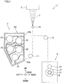
- FIG. 1 is a schematic diagram of a spun yarn take-up machine 1 of the present embodiment.
- the spun yarn take-up machine 1 includes a spinning apparatus 2, a spun yarn drawing apparatus 3, and a yarn winding apparatus 4.
- the up-down direction and the left-right direction in the sheet of FIG. 1 will be referred to as an up-down direction and a left-right direction.
- a direction perpendicular to the sheet of FIG. 1 will be referred to a front-rear direction, and a direction toward the viewer of FIG. 1 will be referred to as a forward direction.
- the spun yarn take-up machine 1 is configured to draw, by the spun yarn drawing apparatus 3, plural yarns Y serially spun out from the spinning apparatus 2 and made of a solidified molten fibrous material such as polyester, and then to wind the yarns Y by the yarn winding apparatus 4.
- the spinning apparatus 2 is configured to generate the yarns Y by continuously spinning out a molten fibrous material such as polyester. To the yarns Y spun out from the spinning apparatus 2, oil is applied at an oil guide 10. The yarns Y are then sent to the spun yarn drawing apparatus 3 via a guide roller 11.
- the spun yarn drawing apparatus 3 is an apparatus for heating and drawing the yarns Y and is provided below the spinning apparatus 2.
- the spun yarn drawing apparatus 3 includes plural godet rollers 31 to 35 housed in a thermal insulation box 20. The details of the spun yarn drawing apparatus 3 will be given later.
- the yarns Y drawn by the spun yarn drawing apparatus 3 are sent to the yarn winding apparatus 4 via the guide roller 12.
- the yarn winding apparatus 4 is an apparatus for winding the yarns Y, and is provided below the spun yarn drawing apparatus 3.
- the yarn winding apparatus 4 includes members such as a bobbin holder 13 and a contact roller 14.
- the bobbin holder 13 is cylindrical in shape, and extends in the front-rear direction.
- the bobbin holder 13 is rotationally driven by an unillustrated motor.
- bobbins B are attached along the axial direction to be side by side. By rotating the bobbin holder 13, the yarn winding apparatus 4 simultaneously winds the yarns Y onto the bobbins B, so as to produce packages P.
- the contact roller 14 makes contact with the surfaces of packages P to adjust the shape of each package P by applying a predetermined contact pressure to each package P.
- FIG. 2 is an enlarged view of the spun yarn drawing apparatus 3 of FIG. 1 .
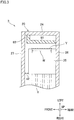
- FIG. 3 is a cross section taken along a line III-III in FIG. 2 . In this figure, the side close to the viewer is the upper side.
- the spun yarn drawing apparatus 3 includes a thermal insulation box 20 and plural (5 in this embodiment) godet rollers 31 to 35 (heating rollers of the present invention) that are accommodated in the thermal insulation box 20.
- the thermal insulation box 20 is a box formed by a top surface portion 21, a right side portion 22, a lower right inclined portion 23, a left side portion 24, a lower left inclined portion 25, a back surface portion 26 (see FIG.
- the front surface portion 27 of the thermal insulation box 20 is attached to the left side portion 24 by an unillustrated hinge, and is openable and closable as the front surface portion 27 swings in the front-rear direction about the hinge, as a door member. Yarn threading of the yarns Y to each of the godet rollers 31 to 35 is performed in a state in which the front surface portion 27 is open.
- Each of the godet rollers 31 to 35 is a roller that sends the yarns Y in the yarn running direction from the yarn inlet 20a toward the yarn outlet 20b, while heating the yarns Y.
- Each of the godet rollers 31 to 35 protrudes toward the front surface portion 27.
- the godet rollers 31 to 35 are provided in this order from the upstream in the yarn running direction.
- the yarns Y are wound onto each of the godet rollers 31 to 35 at a winding angle of less than 360 degrees.
- the yarns Y are wound onto the godet rollers 31 to 35 in order, from the lowest godet roller 31.
- Each of the godet rollers 31 to 35 is rotationally driven by an unillustrated motor at a predetermined yarn feeding speed.
- each of the godet rollers 31 to 35 accommodates an unillustrated heater. The surface of each of the godet rollers 31 to 35 is heated by this heater.
- the lower three godet rollers 31 to 33 are preheating rollers for preliminarily heating the yarns Y before drawing them.
- the roller surface temperature of each of these rollers is arranged to be equal to or higher than the glass transition temperature of the yarns Y (e.g., set at about 90 to 100 degrees centigrade).
- the upper two godet rollers 34 and 35 are conditioning rollers for thermally setting the drawn yarns Y.
- the roller surface temperature of each of these rollers is arranged to be higher than the roller surface temperatures of the lower three godet rollers 31 to 33 (e.g., set at about 150 to 200 degrees centigrade).
- the yarn feeding speeds of the upper two godet rollers 34 and 35 are higher than those of the lower three godet rollers 31 to 33.
- the yarns Y introduced into the thermal insulation box 20 through the yarn inlet 20a are, to begin with, preliminarily heated to a drawable temperature while being transferred by the godet rollers 31 to 33.
- the preliminarily-heated yarns Y are drawn on account of a difference in yarn feeding speed between the godet roller 33 and the godet roller 34. Subsequently, the yarns Y are further heated while being transferred by the godet rollers 34 and 35, with the result that the drawn state is thermally set.
- the yarns Y having been drawn in this way go out from the thermal insulation box 20 through the yarn outlet 20b.
- the godet roller 31 that is the most upstream roller in the yarn running direction is equivalent to a first heating roller of the present invention.
- air introduced into the thermal insulation box 20 through the yarn inlet 20a is guided first.
- the godet roller 35 that is provided on the downstream side in the yarn running direction of the godet roller 31 and is higher in yarn feeding speed and in temperature than the godet roller 31 is equivalent to a second heating roller of the present invention.
- the three godet rollers 32 to 34 provided between the godet roller 31 and the godet roller 35 are equivalent to third heating rollers of the present invention.
- flow control members 41 to 45 are disposed.
- the flow control members 41 to 45 are plate-shaped members provided to protrude from the back surface portion 26 toward the front surface portion 27 of the thermal insulation box 20.
- the flow control members 41 to 45 adjust the air flowing from the yarn inlet 20a to the yarn outlet 20b in the thermal insulation box 20 to be substantially along the yarn running direction.
- the flow control member 45 functions as a heat insulation member.
- shielding members 51 to 53 are disposed.
- the shielding members 51 to 53 extend toward the outer circumferential surface of the godet roller 34, and a leading end portion of each shielding member is close to the outer circumferential surface of the godet roller 34.
- the shielding members 51 to 53 block an accompanied flow generated at the outer circumferential surface of the godet roller 34 and suppress the amplification of the accompanied flow in the thermal insulation box 20. This makes it possible to suppress a large amount of heat from escaping through the yarn outlet 20b as the accompanied flow runs toward the downstream side in the yarn running direction.
- the phrase "around the godet roller” indicates, in connection with a godet roller, a region which is closest to that godet roller as compared to the other godet rollers.
- a phrase "around each of the godet rollers 31 to 35" indicates a region surrounded by any two or more of the top surface portion 21, the right side portion 22, the lower right inclined portion 23, the left side portion 24, the lower left inclined portion 25, the flow control members 41 to 45, the shielding members 51 to 53, a later-described connection wall member 63, and a later-described partition plate 73.
- a phrase “around the godet roller 31" indicates a region surrounded by the lower right inclined portion 23, the later-described connection wall member 63, the later-described partition plate 73, and the flow control member 41.
- a phrase “around the godet roller 35" indicates a region surrounded by the left side portion 24, the top surface portion 21, the flow control member 44, and the flow control member 43.
- the spun yarn drawing apparatus 3 of the present embodiment is provided with a guide path 60 in order to suppress the high-temperature air in the thermal insulation box 20 from flowing out through the yarn outlet 20b and to suppress the power consumption for maintaining the temperature of the yarns Y on the surface of the godet roller 31.
- the guide path 60 for guiding air is provided.
- An inlet 61 of the guide path 60 is disposed at a location closest to the godet roller 35 among the godet rollers 31 to 35, and an outlet 62 of the guide path 60 is disposed at a location closest to the godet roller 31 among the godet rollers 31 to 35.
- the inlet 61 is disposed at a location closer to the godet roller 35 than to the yarn outlet 20b
- the outlet 62 is disposed at a location closer to the godet roller 31 than to the yarn inlet 20a.
- the guide path 60 includes part of the left side portion 24, part of the lower left inclined portion 25, and part of the back surface portion 26 of the thermal insulation box 20, and the connection wall member 63 connecting the left side portion 24, the back surface portion 26, the lower left inclined portion 25, and the back surface portion 26 with one another.
- the connection wall member 63 has a portion extending in the left-right direction and a portion extending in the front-rear direction.
- the guide path 60 is entirely surrounded by the left side portion 24 or the lower left inclined portion 25, the back surface portion 26, and the connection wall member 63.
- the guide path 60 has a closed outer circumference and is a duct in shape.
- the left side portion 24, the lower left inclined portion 25, the back surface portion 26, and the connection wall member 63 are equivalent to the wall members of the present invention.
- a part of the guide path 60 excluding the inlet 61 and its surroundings is, for example, 16 mm ⁇ 155 mm in size (i.e., the cross-sectional area of the part is 2480 mm 2 ).
- the cross-sectional area of the guide path 60 in the direction orthogonal to the longitudinal direction increases toward the inlet 61.
- the area is largest at the inlet 61 (i.e., the cross-sectional area is 6300 mm 2 ) .
- the cross-sectional area of the guide path 60 in the direction orthogonal to the longitudinal direction is preferably 800 mm 2 or larger.
- the length d1 of the gap between the connection wall member 63 of the guide path 60 and the outer circumferential surface of the godet roller 31 falls within the range of 20 to 40 mm.
- the members (the back surface portion 26, the left side portion 24, the lower left inclined portion 25, and the connection wall member 63) constituting the guide path 60 are preferably heat insulation members. With this arrangement, exchange of heat energy between the inside and the outside of the guide path 60 is suppressed, and hence energy loss of the air passing through the guide path 60 is suppressed.
- the inlet 61 of the guide path 60 is a portion surrounded by the left side portion 24, the back surface portion 26, and an upper end portion of the connection wall member 63.
- the outlet 62 of the guide path 60 is a portion surrounded by the lower left inclined portion 25, the back surface portion 26, and a lower end portion of the connection wall member 63.
- the inlet 61 of the guide path 60 is provided so as to overlap a region extending along the front-rear direction which is the axial direction of the godet roller 35, when viewed in the direction (up-down direction in the present embodiment) orthogonal to the axial direction of the godet roller 35 (i.e., when viewed in the direction orthogonal to the front-rear direction) (see FIG. 2 and FIG. 3 ).
- the outlet 62 of the guide path 60 is provided so as to overlap a region extending along the front-rear direction which is the axial direction of the godet roller 31, when viewed in the direction (a direction inclined leftward from the up-down direction in the present embodiment, i.e., the longitudinal direction of the guide path 60) orthogonal to the axial direction of the godet roller 31 (i.e., when viewed in the direction orthogonal to the front-rear direction).
- the region along the front-rear direction that is the axial direction of the godet roller is a surrounding space of the godet roller ranging from the front end face to the rear end face of the godet roller, when viewed in the up-down direction or the left-right direction.
- the inlet 61 is sized to include the wound region W on the outer circumferential surface of the godet roller 35 on which the yarns Y are wound, in the front-rear direction which is the axial direction of the godet roller 35.
- the wound region W indicates a range on the outer circumferential surface of the godet roller, where the yarns Y are wound.
- the wound region W of the godet roller 35 is a range on the outer circumferential surface of the godet roller 35 from a contact point of the yarns Y and the godet roller 35 on the upstream side in the yarn running direction to a contact point of the yarns Y and the godet roller 35 on the downstream side (see FIG.
- the wound region W is a range from a part of the outer circumferential surface of the godet roller 35, where the frontmost yarn Y is wound, to a part where the rearmost yarn Y is wound, when viewed in the yarn running direction (see FIG. 3 ).
- the inlet 61 is open to a first space domain 80A that is in contact with the wound region W where the outer circumferential surface of the godet roller 35 is in contact with the yarns Y, in the internal space of the thermal insulation box 20.
- the outlet 62 is open to a second space domain 80B that is in contact with the wound region W where the outer circumferential surface of the godet roller 31 is in contact with the yarns Y, in the internal space of the thermal insulation box 20.
- the first space domain 80A indicates a space that is in contact with the wound region W where the outer circumferential surface of the godet roller 35 is in contact with the yarns Y in the internal space of the thermal insulation box 20, is a space that is on the outer side of the wound region W where the outer circumferential surface of the godet roller 35 is in contact with the yarns Y, in the radial direction of the godet roller 35, and is a space that is close to the godet roller 35 as compared to the other godet rollers.
- the second space domain 80B indicates a space that is in contact with the wound region W where the outer circumferential surface of the godet roller 31 is in contact with the yarns Y in the internal space of the thermal insulation box 20, is a space that is on the outer side of the wound region W where the outer circumferential surface of the godet roller 31 is in contact with the yarns Y, in the radial direction of the godet roller 31, and is a space that is close to the godet roller 31 as compared to the other godet rollers.
- the second space domain 80B there is a part of a region on the downstream side in the yarn running direction of the outlet 62, and the air passing area of this part is defined by the size d1 of the above-described gap. This air passing area is smaller than the area of a gap between the outlet 62 and the outer circumferential surface of the godet roller 31.
- the spun yarn drawing apparatus 3 further includes a first shielding plate 71, a second shielding plate 72, and a partition plate 73.
- the first shielding plate 71 is a member that is provided in the first space domain 80A, suppresses an amount of air flowing from the godet roller 35 toward the yarn outlet 20b, and guides the suppressed air to the inlet 61.
- the first shielding plate 71 is provided for the godet roller 35 and extends from the left side portion 24 toward a part of the wound region W of the godet roller 35. The part is on the downstream side in the yarn running direction of the inlet 61 of the guide path 60.
- a leading end portion of the first shielding plate 71 is provided to be close to the outer circumferential surface of the godet roller 35.
- the first shielding plate 71 may be entirely provided in the first space domain 80A, or may be partially provided in the first space domain 80A.
- the remaining part of the first shielding plate 71 may be provided in a space domain in contact with at least one of a region on the side of the front end surface of the godet roller 35 as compared to the wound region W of the outer circumferential surface of the godet roller 35 or a region on the side of the rear end face of the godet roller 35 as compared to the wound region W, when viewed in the direction orthogonal to the axial direction of the godet roller 35.
- the remaining part of the first shielding plate 71 may be provided in a region on the downstream side in the yarn running direction of the wound region W of the outer circumferential surface of the godet roller 35 where the yarns Y are wound, when viewed in the axial direction of the godet roller 35.
- the remaining part of the first shielding plate 71 may be provided in a space domain in contact with at least one of a region on the side of the front end surface of the godet roller 35 as compared to the wound region W of the outer circumferential surface of the godet roller 35 or a region on the side of the rear end face of the godet roller 35 as compared to the wound region W, when viewed in the direction orthogonal to the axial direction of the godet roller 35, and in a region on the downstream side in the yarn running direction of the wound region W of the outer circumferential surface of the godet roller 35 where the yarns Y are wound, when viewed in the axial direction of the godet roller 35.
- the leading end portion of the first shielding plate 71 preferably opposes the outer circumferential surface of the godet roller 35. With this arrangement, it is possible to block a larger amount of air flowing along the outer circumferential surface of the godet roller 35 and flowing out from the thermal insulation box 20.
- the leading end portion of the first shielding plate 71 is preferably disposed above the base end portion on the left side portion 24 side. This makes it easy to guide the air to the guide path 60 from the upstream side to the downstream side in the yarn running direction by an accompanied flow generated on the outer circumferential surface of the godet roller 35.
- the first shielding plate 71 extends toward the outer circumferential surface of the lower half of the godet roller 35 when viewed in the front-rear direction.
- the leading end portion of the first shielding plate 71 opposes the outer circumferential surface of the godet roller 35, and the leading end portion of the first shielding plate 71 is disposed above the base end portion.
- the gap between the leading end portion of the first shielding plate 71 and the outer circumferential surface of the godet roller 35 is sized about 2 mm.
- the second shielding plate 72 is a member that is provided in the second space domain 80B, suppresses an amount of air flowing from the outlet 62 toward the yarn inlet 20a, and guides the suppressed air to the wound region W of the outer circumferential surface of the godet roller 31 where the yarns Y are wound.
- the second shielding plate 72 is provided for the godet roller 31 and extends from the lower right inclined portion 23 toward a part of the wound region W of the godet roller 31. The part is on the upstream side in the yarn running direction of the outlet 62 of the guide path 60.
- the gap between the leading end portion of the second shielding plate 72 and the outer circumferential surface of the godet roller 31 is sized about 2 mm.
- the second shielding plate 72 may be entirely provided in the second space domain 80B, or may be partially provided in the second space domain 80B.
- the remaining part of the second shielding plate 72 may be provided in a space domain in contact with at least one of a region on the side of the front end surface of the godet roller 31 as compared to the wound region W of the outer circumferential surface of the godet roller 31 or a region on the side of the rear end face of the godet roller 31 as compared to the wound region W, when viewed in the direction orthogonal to the axial direction of the godet roller 31.
- the remaining part of the second shielding plate 72 may be provided in a region on the upstream side in the yarn running direction of the wound region W of the outer circumferential surface of the godet roller 31 where the yarns Y are wound, when viewed in the axial direction of the godet roller 31.
- the remaining part of the second shielding plate 72 may be provided in a space domain in contact with at least one of a region on the side of the front end surface of the godet roller 31 as compared to the wound region W of the outer circumferential surface of the godet roller 31 or a region on the side of the rear end face of the godet roller 31 as compared to the wound region W, when viewed in the direction orthogonal to the axial direction of the godet roller 31, and in a region on the upstream side in the yarn running direction of the wound region W of the outer circumferential surface of the godet roller 31 where the yarns Y are wound, when viewed in the axial direction of the godet roller 31.
- the partition plate 73 is provided between the godet roller 31 and the godet roller 33.
- the partition plate 73 is a plate-shaped member that protrudes from the back surface portion 26 toward the front surface portion 27 and extends from the connection wall member 63 of the guide path 60 toward the outer circumferential surface of the godet roller 32.
- a leading end portion of the partition plate 73 is provided to be close to the outer circumferential surface of the godet roller 32.
- the distance d2 (see FIG. 3 ) between the front end faces of the godet rollers 31 to 35 cantilevered by the back surface portion 26 and the inner surface of the front surface portion 27 that is an openable and closable door member is 9 mm or shorter.
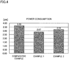
- Example 1 Between spun yarn drawing apparatuses 3 of a comparative example, Example 1, and Example 2, power consumption (kW) of heaters when the yarns Y are heated by the godet rollers 31 to 35 was compared.
- the spun yarn drawing apparatus 3 does not include the guide path 60.
- the spun yarn drawing apparatus 3 is identical with the spun yarn drawing apparatus 3 of the embodiment above, in which the guide path 60, the first shielding plate 71, the second shielding plate 72, and the partition plate 73 are provided in the thermal insulation box 20.
- Example 2 the spun yarn drawing apparatus 3 is different from the spun yarn drawing apparatus 3 of the embodiment above, in which the guide path 60, the first shielding plate 71, and the partition plate 73 are provided in the thermal insulation box 20 but the second shielding plate 72 is not provided.
- the surface temperature of each of the godet rollers 31 to 35 was identical between the comparative example, Example 1, and Example 2.
- the power consumption of the spun yarn drawing apparatus 3 of the comparative example was 3.69 kW.
- the power consumption of the spun yarn drawing apparatus 3 of Example 1 was 2.87 kW and the power consumption of the spun yarn drawing apparatus 3 of Example 2 was 3.16 kW.
- the power consumption was reduced as compared to the comparative example.
- the power consumption was significantly reduced in the spun yarn drawing apparatus 3 of Example 1 in which the second shielding plate 72 was provided.
- the spun yarn drawing apparatus 3 of the present embodiment includes the thermal insulation box 20 having the yarn inlet 20a and the yarn outlet 20b and the godet rollers 31 to 35 accommodated in the thermal insulation box 20.
- the godet rollers 31 to 35 are constituted by the godet roller 31 (first heating roller) which is provided on the most upstream side in the yarn running direction, the godet roller 35 (second heating roller) which is provided on the downstream side in the yarn running direction of the godet roller 31 and is higher in yarn feeding speed and in temperature than the godet roller 31, and the godet rollers 32 to 34 (third heating rollers) which are provided between the godet roller 31 and the godet roller 35 in the yarn running direction.
- the guide path 60 for guiding air is provided in the internal space of the thermal insulation box 20, the guide path 60 for guiding air is provided.
- the inlet 61 of the guide path 60 is disposed at a location closest to the godet roller 35 among the godet rollers 31 to 35, and the outlet 62 of the guide path 60 is disposed at a location closest to the godet roller 31 among the godet rollers 31 to 35.
- the inlet 61 is provided to overlap a region that extends along the axial direction of the godet roller 35 when viewed in the axial direction (front-rear direction) of the godet roller 35, and the outlet 62 is provided to overlap a region extending along the axial direction of the godet roller 31 when viewed in the direction orthogonal to the axial direction (front-rear direction) of the godet roller 31.
- the present embodiment it is possible to guide, to the guide path 60, the high-temperature air flowing along the outer circumferential surface of the godet roller 35 and flowing out from the thermal insulation box 20 due to the accompanied flow.
- the high-temperature air around the godet roller 35 is then guided to around the godet roller 31 by the guide path 60.
- the inlet 61 is provided to overlap a region that extends along the axial direction of the godet roller 35 when viewed in the axial direction of the godet roller 35
- the outlet 62 is provided to overlap a region extending along the axial direction of the godet roller 31 when viewed in the direction orthogonal to the axial direction of the godet roller 31.
- the inlet 61 is disposed at a location closer to the godet roller 35 than to the yarn outlet 20b, and the outlet 62 is disposed at a location closer to the godet roller 31 than to the yarn inlet 20a.
- the flow of air tends to be disturbed at around the inlet 61 and the outlet 62 of the guide path 60.
- the inlet 61 of the guide path 60 is provided at a location close to the yarn outlet 20b, the yarns Y going out from the thermal insulation box 20 through the yarn outlet 20b tend to swing.
- the outlet 62 of the guide path 60 is provided at a location close to the yarn inlet, the yarns Y introduced into the thermal insulation box 20 through the yarn inlet 20a tend to swing.
- the inlet 61 of the guide path 60 is disposed at a location closer to the godet roller 35 than to the yarn outlet 20b, and the outlet 62 of the guide path 60 is disposed at a location closer to the godet roller 31 than to the yarn inlet 20a.
- the air introduced into the guide path 60 through the inlet 61 of the guide path 60 may partially flow out from the thermal insulation box 20 through the yarn outlet 20b, on account of an accompanied flow generated by the running of the yarns Y.
- the inlet 61 of the guide path 60 is disposed at a location closer to the godet roller 35 than to the yarn outlet 20b, it is possible to suppress the air introduced into the guide path 60 through the inlet 61 of the guide path 60 from partially flowing out from the thermal insulation box 20 through the yarn outlet 20b.
- the guide path 60 is entirely provided in the thermal insulation box 20. In the present embodiment, because the temperature of the air passing through the guide path 60 is maintained in the thermal insulation box 20, energy loss of the high-temperature air is further reduced.
- the guide path 60 in a cross section orthogonal to the longitudinal direction of the guide path 60, the guide path 60 is entirely surrounded by the left side portion 24, the lower left inclined portion 25, the back surface portion 26, and the connection wall member 63.
- the inlet 61 when viewed in the direction orthogonal to the axial direction (front-rear direction) of the godet roller 35, the inlet 61 is sized to encompass the wound region W of the outer circumferential surface of the godet roller 35 where the yarns Y are wound, in the axial direction (front-rear direction) of the godet roller 35.
- uniformization of the flow of air at around the inlet 61 of the guide path 60 is facilitated between the yarns Y. It is therefore possible to further suppress the yarn swing at around the inlet 61 of the guide path 60 due to the disturbance of airflow, and to suppress the adverse influence on the quality of the yarns Y.
- the first shielding plate 71 is further provided in the first space domain 80A that is in contact with the wound region W of the outer circumferential surface of the godet roller 35 where the yarns Y are wound in the internal space of the thermal insulation box 20, suppresses an amount of air flowing from the godet roller 35 toward the yarn outlet 20b, and guides the suppressed air to the inlet 61 of the guide path 60.
- the second shielding plate 72 is further provided in the second space domain 80B that is in contact with the wound region W of the outer circumferential surface of the godet roller 31 where the yarns Y are wound in the internal space of the thermal insulation box 20, suppresses an amount of air flowing from the outlet 62 of the guide path 60 to the yarn inlet 20a, and guides the suppressed air to the wound region on the outer circumferential surface of the godet roller 31 where the yarns Y are wound.
- the partition plate 73 is further provided between the godet roller 31 and the godet roller 33. Air heated in the thermal insulation box 20 exists around the godet roller 33, and the yarns Y having already heated to a high temperature are wound onto the godet roller 33. If the high-temperature air having been guided to around the godet roller 31 through the guide path 60 moves to around the godet roller 33, the godet roller 33 may become excessively high in temperature, and the quality of the yarns may be deteriorated. In the present embodiment, it is possible to suppress the high-temperature air around the godet roller 31 from moving to around the godet roller 33 by the partition plate 73. It is therefore possible to suppress the godet roller 33 from being excessively high in temperature.
- the inlet 61 of the guide path 60 is open to the first space domain 80A that is in contact with the wound region W of the outer circumferential surface of the godet roller 35 where the yarns Y are wound in the internal space of the thermal insulation box 20, whereas the outlet 62 is open to the second space domain 80B that is in contact with the wound region W on the outer circumferential surface of the godet roller 31 where the yarns Y are wound in the internal space of the thermal insulation box 20.
- the flow of air tends to be disturbed at around the inlet 61 and the outlet 62 of the guide path 60.
- the inlet 61 and the outlet 62 of the guide path 60 are open toward a part of the yarns Y running in the yarn running direction, which is not wound onto the godet roller, yarn swing may occur due to the disturbance of air, and the quality of the yarns Y may be adversely affected.
- the inlet 61 of the guide path 60 is open to the first space domain 80A and the outlet 62 is open to the second space domain 80B. It is therefore possible to further suppress the occurrence of yarn swing.
- the area of this part is an air passing area.
- This air passing area is smaller than the area of a gap between the outlet 62 and the outer circumferential surface of the godet roller 31.
- the pressure static pressure
- the flow of air from the guide path 60 toward the godet roller 31 is facilitated. In other words, the flow of air is facilitated at the part where the air passing area is narrow.
- the air introduced to around the godet roller 31 through the guide path 60 is facilitated to flow into the part where the air passing area is narrow. It is therefore possible to allow a large amount of high-temperature air to flow into the guide path 60 through the inlet 61 of the guide path 60, and hence a large amount of high-temperature air is introduced to around the godet roller 31. This makes it possible to further efficiently utilize the heat energy.
- the size d1 of the gap between the guide path 60 and the outer circumferential surface of the godet roller 31, which defines part of the air passing area is 20 to 40 mm.
- the size of the gap between the guide path 60 and the outer circumferential surface of the godet roller 31 i.e., the value partially defining the air passing area
- the flow rate of an accompanied flow generated by the rotation of the godet roller 31 is high.
- the pressure (static pressure) is lowered and the flow of air from the guide path 60 toward the godet roller 31 is facilitated.
- a large part of the high-temperature air guided to around the godet roller 31 through the guide path 60 is therefore supplied to the downstream side in the yarn running direction through the above-described gap. It is therefore possible to suppress the high-temperature air guided by the guide path 60 from flowing out from the thermal insulation box 20 through the yarn inlet 20a.
- the air is facilitated to flow into the gap, it is possible to allow a large amount of the high-temperature air to flow into the guide path 60 through the inlet 61 of the guide path 60, and hence a large amount of high-temperature air is introduced to around the godet roller 31. This makes it possible to further efficiently utilize the heat energy.
- the front surface portion 27 of the thermal insulation box 20 is a door member that is openable and closable
- the godet rollers 31 to 35 are cantilevered by the back surface portion 26, and the distance d2 between the front end faces and the inner surface of the front surface portion 27 is 4 mm or shorter.
- the distance between the front end faces of the godet rollers 31 to 35 and the front surface portion 27 is long, air disadvantageously flows between the front end faces of the godet rollers 31 to 35 and the front surface portion 27, with the result that the high-temperature air cannot be efficiently guided by the guide path 60.
- the present embodiment because the air less easily flows between the front end faces of the godet rollers 31 to 35 and the front surface portion 27, the high-temperature air is efficiently guided by the guide path 60.
- the guide path 60 guides the air around the godet roller 35 to around the godet roller 31, without guiding the air to around the godet rollers 32 to 34.
- the air around the godet roller 34 may be guided to around the godet roller 31 without being guided to the godet rollers 32 ad 33.
- the godet roller 34 which is provided on the downstream side in the yarn running direction of the godet roller 31 equivalent to the first heating roller and is higher in yarn feeding speed and in temperature than the godet roller 31, is equivalent to the second heating roller.
- the godet rollers 32 and 33 provided between the godet roller 31 and the godet roller 34 are equivalent to the third heating rollers.
- the guide path 60 includes part of the left side portion 24, part of the lower left inclined portion 25, and part of the back surface portion 26 of the thermal insulation box 20, and the connection wall member 63 connecting the left side portion 24, the back surface portion 26, the lower left inclined portion 25, and the back surface portion 26 with one another.
- the guide path 60 is entirely surrounded by the left side portion 24 or the lower left inclined portion 25, the back surface portion 26, and the connection wall member 63.
- the guide path 60 may include part of the left side portion 24, part of the lower left inclined portion 25, part of the back surface portion 26, and part of the front surface portion 27 of the thermal insulation box 20, a plate member extending from the back surface portion 26 toward the front surface portion 27, and a sealing member attached to the front end of the plate member.
- the sealing member is provided at a gap between the plate member and the front surface portion 27.
- the guide path 60 is entirely surrounded by the left side portion 24 or the lower left inclined portion 25, the back surface portion 26, the front surface portion 27, the plate member, and the sealing member.
- the inlet 61 is partially provided to overlap a region that extends along the axial direction of the godet roller 35 when viewed in the axial direction of the godet roller 35
- the outlet 62 is partially provided to overlap a region extending along the axial direction of the godet roller 31 when viewed in the direction orthogonal to the axial direction of the godet roller 31.
- the sealing member may be attached to the front ends of the first shielding plate 71, the second shielding plate 72, the partition plate 73, the flow control members 41 to 45, and the shielding members 51 to 53.
- This arrangement eliminates gaps between the front surface portion 27 in the closed state and the first shielding plate 71, the second shielding plate 72, the partition plate 73, and the front ends of the flow control members 41 to 45, and the shielding members 51 to 53.
- the air is prevented from passing through the gap, and hence the generation of an unintended airflow in the internal space of the thermal insulation box 20 is prevented.
- the sealing member may not be attached to all of the front ends of the first shielding plate 71, the second shielding plate 72, the partition plate 73, the flow control members 41 to 45, and the shielding members 51 to 53, and may be attached to at least one or more of them.
- the guide path 60 may not be entirely surrounded by wall members.
- the guide path 60 may include the left side portion 24, the lower left inclined portion 25, and the back surface portion 26 of the thermal insulation box 20, and a plate member protruding from the back surface portion 26 toward the front surface portion 27.
- the guide path 60 is not surrounded by a wall member on the front side.
- the guide path 60 While in the embodiment above the guide path 60 is provided inside the thermal insulation box 20, the guide path 60 may be provided outside the thermal insulation box 20.
- the guide path 60 is a heat insulation member, has a closed outer circumference, and is duct in shape.
- the gap between the leading end portion of the second shielding plate 72 and the outer circumferential surface of the godet roller 31 is sized about 2 mm.
- the gap between the leading end portion of the second shielding plate 72 and the outer circumferential surface of the godet roller 31 may be longer than about 2 mm.
- the second shielding plate 72 has a function of blocking low-temperature air introduced into the thermal insulation box 20 through the yarn inlet 20a.
- the temperature of the air around the godet rollers 32 to 35 provided on the downstream side in the yarn running direction of the godet roller 31 may be higher than expected.
- the surface temperatures of the godet rollers 32 to 35 may become excessively high and may adversely affect the quality of the yarns Y.
- the distance between the leading end portion of the second shielding plate 72 and the outer circumferential surface of the godet roller 31 is preferably set at a value that falls within a range in which the surface temperatures of the godet rollers 32 to 35 do not become too high and that suppresses the air guided to around the godet roller 31 by the guide path 60 from flowing out from the thermal insulation box through the yarn inlet 20a most.
- the size of the gap between the leading end portion of the second shielding plate 72 and the outer circumferential surface of the godet roller 31 is, for example, determined to be a size falling within the range of 2 mm to 35 mm.
- the spun yarn drawing apparatus of the present invention may include a second shielding plate driver which is configured to move the second shielding plate 72 in order to adjust the distance between the leading end portion of the second shielding plate 72 and the outer circumferential surface of the godet roller 31.
- the distance between the leading end portion of the second shielding plate 72 and the outer circumferential surface of the godet roller 31 is automatically adjusted in accordance with the temperature inside the thermal insulation box 20, the surface temperature of each godet roller, etc. This arrangement prevents the temperature of the air around the godet rollers 32 to 35 provided on the downstream side in the yarn running direction of the godet roller 31 from becoming higher than expected.
- the first shielding plate 71 may be movable between a near position close to the outer circumferential surface of the godet roller 35 and a retracted position remote from the outer circumferential surface of the godet roller 35 as compared to the near position.
- the second shielding plate 72 may be movable between a near position close to the outer circumferential surface of the godet roller 31 and a retracted position remote from the outer circumferential surface of the godet roller 31 as compared to the near position.
- the shielding members 51 and 52 may be movable between a near position close to the outer circumferential surface of the godet roller 34 and a retracted position remote from the outer circumferential surface of the godet roller 34 as compared to the near position.
- the first shielding plate 71, the second shielding plate 72, and the shielding members 51 and 52 are moved to the retracted positions and these members are temporarily remote from the godet roller 35. This makes it easy to perform the yarn threading to the godet rollers.
- one or more of the first shielding plate 71, the second shielding plate 72, and the partition plate 73 may not be provided.
- a slidable shutter may be attached to the inlet 61 of the guide path 60. As the shutter slides along the inlet 61, the area of the inlet 61 is changed. In this way, the flow amount of the air flowing into the guide path 60 can be adjusted.
- the shutter may be manually slid by an operator, or automatically slid y a shutter driver provided for moving the shutter.
Landscapes
- Engineering & Computer Science (AREA)
- Textile Engineering (AREA)
- Mechanical Engineering (AREA)
- Physics & Mathematics (AREA)
- Thermal Sciences (AREA)
- Yarns And Mechanical Finishing Of Yarns Or Ropes (AREA)
- Spinning Methods And Devices For Manufacturing Artificial Fibers (AREA)
Abstract
Description
- The present invention relates to a spun yarn drawing apparatus including a thermal insulation box in which a yarn heating roller for heating yarns is accommodated.
- Patent Literature 1 (
Japanese Patent No. 6088948 - To the yarn inlet of the thermal insulation box of
Patent Literature 1 and its surroundings, low-temperature air outside the thermal insulation box flows though the yarn inlet. Furthermore, onto the heating roller provided in the vicinity of the yarn inlet, low-temperature yarns sent from the outside through the yarn inlet are wound. For these reasons, in the thermal insulation box ofPatent Literature 1, loss of heat energy through the yarn outlet is suppressed but loss of heat energy due to reasons such as low-temperature air flowing in through the yarn inlet cannot be suppressed, with the result that a power consumption amount required for heating the rollers is increased. - Patent Literature 2 (
Japanese Laid-Open Patent Publication No. 2014-101611 - The air duct guides high-temperature air around a yarn outlet of the heat retaining box to a low-temperature air region that is provided in the vicinity of the yarn inlet in the heat retaining box. This arrangement makes it possible to efficiently utilize the heat energy.
- In the apparatus of
Patent Literature 2, however, high-temperature air at around the yarn outlet is guided to the air duct along a direction orthogonal to an end face of each roller, i.e., along a direction orthogonal to the running direction of yarns wound onto the rollers. The high-temperature air having passed through the air duct is then guided to the low-temperature air region, in the direction orthogonal to the running direction of the yarns wound onto the rollers. As a result, at around the inlet and outlet of the air duct, the airflow may be disturbed in the direction orthogonal to the running direction of the yarns, and hence yarn swing may occur. Such yarn swing adversely affects the quality of the yarns. - An object of the present invention is to provide a spun yarn drawing apparatus in which yarn swing of yarns wound onto rollers is suppressed while heat energy is efficiently utilized in a thermal insulation box.
- According to a first aspect of the invention, a spun yarn drawing apparatus includes: a thermal insulation box which includes a yarn inlet through which yarns are introduced and a yarn outlet through which the yarns go out; and heating rollers which are accommodated in the thermal insulation box and are configured to feed the yarn in a yarn running direction that is a direction toward the yarn outlet from the yarn inlet, while heating the yarns, the heating rollers including a first heating roller which is provided on the most upstream side in the yarn running direction, a second heating roller which is provided on the downstream side of the first heating roller in the yarn running direction and is higher in yarn feeding speed and in temperature than the first heating roller, and at least one third heating roller which is provided between the first heating roller and the second heating roller in the yarn running direction, a guide path for guiding air being provided in the internal space of the thermal insulation box to have an inlet which is provided to be closest to the second heating roller among the heating rollers and an outlet which is provided to be closest to the first heating roller among the heating rollers, the inlet at least partially overlapping a region extending along an axial direction of the second heating roller when viewed in a direction orthogonal to the axial direction of the second heating roller, and the outlet at least partially overlapping a region extending along an axial direction of the first heating roller when viewed in a direction orthogonal to the axial direction of the first heating roller.
- To a part of the thermal insulation box where the first heating roller is provided, outside low-temperature air flows in through the yarn inlet. Onto the first heating roller, the low-temperature yarns introduced from the outside are wound. A large amount of energy is therefore consumed to maintain the temperature of the first heating roller. Meanwhile, the high-temperature air around the second heating roller flows out from the thermal insulation box through the outlet on account of an accompanied flow generated by the rotation of the roller and the running of the yarns wound onto the roller. This causes loss of a large amount of energy.
- According to the first aspect of the invention, it is possible to guide, to the guide path, the high-temperature air flowing along the outer circumferential surface of the second heating roller and flowing out from the thermal insulation box due to the accompanied flow. The high-temperature air around the second heating roller is then guided to around the first heating roller by the guide path. With this arrangement, energy loss due to the outflow of the high-temperature air from the thermal insulation box is suppressed and the temperature around the first heating roller is increased, with the result that the heat energy is effectively utilized in the thermal insulation box. The inlet and the outlet of the guide path at least partially overlap a region extending along the axial direction of the heating roller when viewed in the direction orthogonal to the axial direction of the heating roller. With this arrangement, the high-temperature air around the second heating roller is guided to the guide path in the direction in parallel to the running direction of the yarns, and is further sent to around the first heating roller in the direction in parallel to the running direction of the yarns. This arrangement suppresses yarn swing of the yarns wound onto the heating rollers.
- According to a second aspect of the invention, the spun yarn drawing apparatus of the first aspect is arrange such that the inlet is positionally closer to the second heating roller than to the yarn outlet, and the outlet is positionally closer to the first heating roller than to the yarn inlet.
- The flow of air tends to be disturbed at around the inlet and the outlet of the guide path. When the inlet of the guide path is provided at a location close to the yarn outlet, the yarns going out from the thermal insulation box through the yarn outlet tend to swing. When the outlet of the guide path is provided at a location close to the yarn inlet, the yarns introduced into the thermal insulation box through the yarn inlet tend to swing. According to the second aspect of the invention, the inlet of the guide path is disposed at a location closer to the second heating roller than to the yarn outlet, and the outlet of the guide path is disposed at a location closer to the first heating roller than to the yarn inlet. With this arrangement, it is possible to suppress swing of the yarns introduced into the thermal insulation box through the yarn inlet and yarn swing of the yarns going out from the thermal insulation box through the yarn outlet. When the inlet of the guide path is provided at a location close to the yarn outlet, the air introduced into the guide path through the inlet of the guide path may partially flow out from the thermal insulation box through the yarn outlet, on account of an accompanied flow generated by the running of the yarn. According to the second aspect of the invention, because the inlet of the guide path is disposed at a location closer to the second heating roller than to the yarn outlet, it is possible to suppress the air introduced into the guide path through the inlet of the guide path from partially flowing out from the thermal insulation box through the yarn outlet.
- According to a third aspect of the invention, the spun yarn drawing apparatus of the first or second aspect is arranged such that the guide path is entirely provided inside the thermal insulation box.
- According to the third aspect of the invention, because the temperature of the air passing through the guide path is maintained in the thermal insulation box, energy loss of the high-temperature air is further reduced.
- According to a fourth aspect of the invention, the spun yarn drawing apparatus of any one of the first to third aspects is arranged such that, in a cross section orthogonal to a longitudinal direction of the guide path, the guide path is entirely surrounded by wall members.
- According to the fourth aspect of the invention, it is possible to prevent the air passing through the guide path from leaking in the middle to the inside of the thermal insulation box. It is therefore possible to efficiently guide the high-temperature air to around the first heating roller, and to further efficiently utilize the heat energy.
- According to a fifth aspect of the invention, the spun yarn drawing apparatus of any one of the first to fourth aspects is arranged such that, when viewed in a direction orthogonal to the axial direction of the second heating roller, the inlet is sized to encompass a wound region on an outer circumferential surface of the second heating roller in the axial direction of the second heating roller, the wound region being a region on which the yarns are wound.
- According to the fifth aspect of the invention, uniformization of the flow of air at around the inlet of the guide path is facilitated between the yarns. It is therefore possible to further suppress the swing at around the inlet of the guide path due to the disturbance of airflow, and to suppress the adverse influence on the quality of the yarns.
- According to a sixth aspect of the invention, the spun yarn drawing apparatus of the fifth aspect further includes a first shielding plate which is provided in a first space domain in contact with the wound region of the second heating roller in the internal space of the thermal insulation box, suppresses an amount of the air flowing from the second heating roller toward the yarn outlet, and guides the suppressed air to the inlet.
- According to the sixth aspect of the invention, it is possible to suppress an amount of air flowing along the outer circumferential surface of the second heating roller and flowing out from the thermal insulation box. Furthermore, it is possible to guide a larger amount of air to the guide path from the upstream side to the downstream side in the yarn running direction by an accompanied flow generated on the outer circumferential surface of the second heating roller. This makes it possible to further efficiently utilize the heat energy.
- According to a seventh aspect of the invention, the spun yarn drawing apparatus of any one of the first to sixth aspects further includes a second shielding plate which is provided in a second space domain in contact with a wound region on an outer circumferential surface of the first heating roller in the internal space of the thermal insulation box, suppresses an amount of the air flowing from the outlet toward the yarn inlet, and guides the suppressed air to the wound region of the first heating roller, the wound region being a region on which the yarns are wound.
- According to the seventh aspect of the invention, it is possible to suppress the high-temperature air guided by the guide path from flowing out from the thermal insulation box through the yarn inlet and to guide the air to the wound region on the outer circumferential surface of the first heating roller where the yarns are wound. This makes it possible to further suppress the energy consumption when the temperature of the first heating roller is maintained, and to further efficiently utilize the heat energy.
- According to an eighth aspect of the invention, the spun yarn drawing apparatus of any one of the first to seventh aspects further includes a partition plate which is provided between the first heating roller and the at least one third heating roller.
- If the high-temperature air having been guided to around the first heating roller through the guide path moves to around the third heating roller, the third heating roller may become excessively high in temperature, and the quality of the yarns may be deteriorated. According to the eighth aspect of the invention, it is possible to suppress the high-temperature air around the first heating roller from moving to around the third heating roller by the partition plate. It is therefore possible to suppress the third heating roller from being excessively high in temperature.
- According to a ninth aspect of the invention, the spun yarn drawing apparatus of the seventh aspect is arranged such that the inlet is open to the first space domain which is in contact with the wound region of the second heating roller in the internal space of the thermal insulation box, and the outlet is open to the second space domain.
- The flow of air tends to be disturbed at around the inlet and the outlet of the guide path. When the inlet and the outlet of the guide path heating roller are open toward a part of the running in the yarn running direction, which is not wound onto the heating roller, yarn swing may occur due to the disturbance of air, and the quality of the yarns may be adversely affected. According to the ninth aspect of the invention, the inlet of the guide path is open to the first space domain and the outlet is open to the second space domain. It is therefore possible to further suppress the occurrence of yarn swing.
- According to a tenth aspect of the invention, the spun yarn drawing apparatus of the ninth aspect is arranged such that an air passing area of at least part of a region of the second space domain is narrower than an area of a gap between the outlet and the outer circumferential surface of the first heating roller, the region being on the downstream side of the outlet in the yarn running direction.
- At the part where the air passing area is narrow, the flow rate of an accompanied flow generated by the rotation of the first heating roller is high. As a result, the pressure (static pressure) is lowered and the flow of air from the guide path toward the first heating roller is facilitated. In other words, the flow of air is facilitated at the part where the air passing area is narrow. According to the tenth aspect of the invention, the air introduced to around the first heating roller through the guide path is facilitated to flow into the part of the second space domain where the air passing area is narrow. It is therefore possible to allow a large amount of high-temperature air to flow into the guide path through the inlet of the guide path, and hence a large amount of high-temperature air is introduced to around the first heating roller. This makes it possible to further efficiently utilize the heat energy.
- According to an eleventh aspect of the invention, the spun yarn drawing apparatus of the tenth aspect is arranged such that a gap between the guide path and the outer circumferential surface of the first heating roller, which defines part of the air passing area, is sized 20 to 40 mm.
- According to the eleventh aspect of the invention, the size of the gap between the guide path and the outer circumferential surface of the first heating roller (i.e., the value partially defining the air passing area) is arranged to be as small as possible within the range in which the leading end of the suction gun is allowed to pass through the gap in order to suck the yarns at the time of the yarn threading to the heating roller. At the part where the gap is narrow, the flow rate of an accompanied flow generated by the rotation of the first heating roller is high. As a result, the pressure (static pressure) is lowered and the flow of air from the guide path toward the first heating roller is facilitated. A large part of the high-temperature air guided to around the first heating roller through the guide path is therefore supplied to the downstream side in the yarn running direction through the above-described gap. It is therefore possible to suppress the high-temperature air guided by the guide path from flowing out from the thermal insulation box through the yarn inlet. Furthermore, because the air is facilitated to flow into the gap, it is possible to allow a large amount of the high-temperature air to flow into the guide path through the inlet of the guide path, and hence a large amount of high-temperature air is introduced to around the first heating roller. This makes it possible to further efficiently utilize the heat energy.
- According to a twelfth aspect of the invention, the spun yarn drawing apparatus of any one of the first to eleventh aspects is arranged such that a wall surface on one side of the thermal insulation box in the axial direction of the heating rollers is a door member, and the heating rollers are cantilevered by a wall surface on the other side in the axial direction of the heating rollers and the distance between end faces of the heating rollers on the one side and an inner surface of the door member is 9 mm or shorter.
- When the distance between the end faces of the godet heating rollers on the one side and the door member is long, air disadvantageously flows between the end faces of the heating rollers and the door member, with the result that the high-temperature air cannot be efficiently guided by the guide path. According to the twelfth aspect of the invention, because the air less easily flows between the end faces of the heating rollers and the door member, the high-temperature air is efficiently guided by the guide path.
- In a spun yarn drawing apparatus, yarn swing of yarns wound onto rollers is suppressed while heat energy is efficiently utilized in a thermal insulation box.
-
-
FIG. 1 is a schematic representation of a spun yarn take-up machine including a spun yarn drawing apparatus of an embodiment. -
FIG. 2 is an enlarged view of the spun yarn drawing apparatus ofFIG. 1 . -
FIG. 3 is a cross section taken along a line III-III inFIG. 2 . -
FIG. 4 shows power consumption of a spun yarn drawing apparatus of each of examples and a comparative example. - The following will describe a preferred embodiment of the present invention with reference to figures.
FIG. 1 is a schematic diagram of a spun yarn take-upmachine 1 of the present embodiment. As shown inFIG. 1 , the spun yarn take-upmachine 1 includes aspinning apparatus 2, a spunyarn drawing apparatus 3, and ayarn winding apparatus 4. Hereinafter, the up-down direction and the left-right direction in the sheet ofFIG. 1 will be referred to as an up-down direction and a left-right direction. Furthermore, a direction perpendicular to the sheet ofFIG. 1 will be referred to a front-rear direction, and a direction toward the viewer ofFIG. 1 will be referred to as a forward direction. - As shown in
FIG. 1 , the spun yarn take-upmachine 1 is configured to draw, by the spunyarn drawing apparatus 3, plural yarns Y serially spun out from thespinning apparatus 2 and made of a solidified molten fibrous material such as polyester, and then to wind the yarns Y by theyarn winding apparatus 4. - The
spinning apparatus 2 is configured to generate the yarns Y by continuously spinning out a molten fibrous material such as polyester. To the yarns Y spun out from thespinning apparatus 2, oil is applied at anoil guide 10. The yarns Y are then sent to the spunyarn drawing apparatus 3 via aguide roller 11. - The spun
yarn drawing apparatus 3 is an apparatus for heating and drawing the yarns Y and is provided below thespinning apparatus 2. The spunyarn drawing apparatus 3 includesplural godet rollers 31 to 35 housed in athermal insulation box 20. The details of the spunyarn drawing apparatus 3 will be given later. - The yarns Y drawn by the spun
yarn drawing apparatus 3 are sent to theyarn winding apparatus 4 via theguide roller 12. Theyarn winding apparatus 4 is an apparatus for winding the yarns Y, and is provided below the spunyarn drawing apparatus 3. Theyarn winding apparatus 4 includes members such as abobbin holder 13 and acontact roller 14. Thebobbin holder 13 is cylindrical in shape, and extends in the front-rear direction. Thebobbin holder 13 is rotationally driven by an unillustrated motor. To thebobbin holder 13, bobbins B are attached along the axial direction to be side by side. By rotating thebobbin holder 13, theyarn winding apparatus 4 simultaneously winds the yarns Y onto the bobbins B, so as to produce packages P. Thecontact roller 14 makes contact with the surfaces of packages P to adjust the shape of each package P by applying a predetermined contact pressure to each package P. - The following will describe the structure of the spun
yarn drawing apparatus 3 of the present embodiment with reference toFIG. 2 andFIG. 3 .FIG. 2 is an enlarged view of the spunyarn drawing apparatus 3 ofFIG. 1 .FIG. 3 is a cross section taken along a line III-III inFIG. 2 . In this figure, the side close to the viewer is the upper side. The spunyarn drawing apparatus 3 includes athermal insulation box 20 and plural (5 in this embodiment)godet rollers 31 to 35 (heating rollers of the present invention) that are accommodated in thethermal insulation box 20. Thethermal insulation box 20 is a box formed by atop surface portion 21, aright side portion 22, a lower right inclinedportion 23, aleft side portion 24, a lower left inclinedportion 25, a back surface portion 26 (seeFIG. 3 ), and a front surface portion 27 (seeFIG. 3 ). At a lower part of theright side portion 22 of thethermal insulation box 20, aninlet 20a is formed to introduce yarns Y into thethermal insulation box 20. At an upper part of theright side portion 22 of thethermal insulation box 20, anoutlet 20b is formed to take yarns Y out from thethermal insulation box 20. Thefront surface portion 27 of thethermal insulation box 20 is attached to theleft side portion 24 by an unillustrated hinge, and is openable and closable as thefront surface portion 27 swings in the front-rear direction about the hinge, as a door member. Yarn threading of the yarns Y to each of thegodet rollers 31 to 35 is performed in a state in which thefront surface portion 27 is open. - Each of the
godet rollers 31 to 35 is a roller that sends the yarns Y in the yarn running direction from theyarn inlet 20a toward theyarn outlet 20b, while heating the yarns Y. Each of thegodet rollers 31 to 35 protrudes toward thefront surface portion 27. In thethermal insulation box 20, thegodet rollers 31 to 35 are provided in this order from the upstream in the yarn running direction. The yarns Y are wound onto each of thegodet rollers 31 to 35 at a winding angle of less than 360 degrees. The yarns Y are wound onto thegodet rollers 31 to 35 in order, from thelowest godet roller 31. Each of thegodet rollers 31 to 35 is rotationally driven by an unillustrated motor at a predetermined yarn feeding speed. (The rotational direction is indicated by an arrow at each of thegodet rollers 31 to 35 inFIG. 2 .) Each of thegodet rollers 31 to 35 accommodates an unillustrated heater. The surface of each of thegodet rollers 31 to 35 is heated by this heater. - The lower three
godet rollers 31 to 33 are preheating rollers for preliminarily heating the yarns Y before drawing them. The roller surface temperature of each of these rollers is arranged to be equal to or higher than the glass transition temperature of the yarns Y (e.g., set at about 90 to 100 degrees centigrade). Meanwhile, the upper twogodet rollers godet rollers 31 to 33 (e.g., set at about 150 to 200 degrees centigrade). The yarn feeding speeds of the upper twogodet rollers godet rollers 31 to 33. - The yarns Y introduced into the
thermal insulation box 20 through theyarn inlet 20a are, to begin with, preliminarily heated to a drawable temperature while being transferred by thegodet rollers 31 to 33. The preliminarily-heated yarns Y are drawn on account of a difference in yarn feeding speed between thegodet roller 33 and thegodet roller 34. Subsequently, the yarns Y are further heated while being transferred by thegodet rollers thermal insulation box 20 through theyarn outlet 20b. - In the present embodiment, the
godet roller 31 that is the most upstream roller in the yarn running direction is equivalent to a first heating roller of the present invention. To around thegodet roller 31 that is the first heating roller, air introduced into thethermal insulation box 20 through theyarn inlet 20a is guided first. Thegodet roller 35 that is provided on the downstream side in the yarn running direction of thegodet roller 31 and is higher in yarn feeding speed and in temperature than thegodet roller 31 is equivalent to a second heating roller of the present invention. The threegodet rollers 32 to 34 provided between thegodet roller 31 and thegodet roller 35 are equivalent to third heating rollers of the present invention. - In the
thermal insulation box 20,flow control members 41 to 45 are disposed. Theflow control members 41 to 45 are plate-shaped members provided to protrude from theback surface portion 26 toward thefront surface portion 27 of thethermal insulation box 20. Theflow control members 41 to 45 adjust the air flowing from theyarn inlet 20a to theyarn outlet 20b in thethermal insulation box 20 to be substantially along the yarn running direction. There is a narrow gap between theflow control member 45 and theright side portion 22. The formation of this gap suppresses heat exchange between the low-temperature air outside thethermal insulation box 20 and the high-temperature air inside thethermal insulation box 20. In other words, theflow control member 45 functions as a heat insulation member. - In the
thermal insulation box 20, furthermore, shieldingmembers 51 to 53 are disposed. The shieldingmembers 51 to 53 extend toward the outer circumferential surface of thegodet roller 34, and a leading end portion of each shielding member is close to the outer circumferential surface of thegodet roller 34. The shieldingmembers 51 to 53 block an accompanied flow generated at the outer circumferential surface of thegodet roller 34 and suppress the amplification of the accompanied flow in thethermal insulation box 20. This makes it possible to suppress a large amount of heat from escaping through theyarn outlet 20b as the accompanied flow runs toward the downstream side in the yarn running direction. - The phrase "around the godet roller" indicates, in connection with a godet roller, a region which is closest to that godet roller as compared to the other godet rollers. In the present embodiment, a phrase "around each of the
godet rollers 31 to 35" indicates a region surrounded by any two or more of thetop surface portion 21, theright side portion 22, the lower right inclinedportion 23, theleft side portion 24, the lower left inclinedportion 25, theflow control members 41 to 45, the shieldingmembers 51 to 53, a later-describedconnection wall member 63, and a later-describedpartition plate 73. For example, a phrase "around thegodet roller 31" indicates a region surrounded by the lower right inclinedportion 23, the later-describedconnection wall member 63, the later-describedpartition plate 73, and theflow control member 41. For example, a phrase "around thegodet roller 35" indicates a region surrounded by theleft side portion 24, thetop surface portion 21, theflow control member 44, and theflow control member 43. - To the
yarn inlet 20a of thethermal insulation box 20 of the spunyarn drawing apparatus 3 and its surroundings, low-temperature air outside thethermal insulation box 20 flows though theyarn inlet 20a. In thethermal insulation box 20, low-temperature yarns Y introduced from the outside through theyarn inlet 20a are wound onto thegodet roller 31 which is the most upstream godet roller in the yarn running direction. A large amount of energy is therefore consumed to maintain the temperature of the yarns Y on the surface of thegodet roller 31 to be sufficiently high. Meanwhile, the high-temperature air around thegodet roller 35 flows out from thethermal insulation box 20 through theyarn outlet 20b on account of an accompanied flow generated by the rotation of the yarns Y wound onto thegodet roller 35. This causes loss of a large amount of energy. - Under this circumstance, the spun
yarn drawing apparatus 3 of the present embodiment is provided with aguide path 60 in order to suppress the high-temperature air in thethermal insulation box 20 from flowing out through theyarn outlet 20b and to suppress the power consumption for maintaining the temperature of the yarns Y on the surface of thegodet roller 31. - In the
thermal insulation box 20, theguide path 60 for guiding air is provided. Aninlet 61 of theguide path 60 is disposed at a location closest to thegodet roller 35 among thegodet rollers 31 to 35, and anoutlet 62 of theguide path 60 is disposed at a location closest to thegodet roller 31 among thegodet rollers 31 to 35. As shown inFIG. 2 , theinlet 61 is disposed at a location closer to thegodet roller 35 than to theyarn outlet 20b, and theoutlet 62 is disposed at a location closer to thegodet roller 31 than to theyarn inlet 20a. - The
guide path 60 includes part of theleft side portion 24, part of the lower left inclinedportion 25, and part of theback surface portion 26 of thethermal insulation box 20, and theconnection wall member 63 connecting theleft side portion 24, theback surface portion 26, the lower left inclinedportion 25, and theback surface portion 26 with one another. As shown inFIG. 3 , theconnection wall member 63 has a portion extending in the left-right direction and a portion extending in the front-rear direction. In a cross section orthogonal to the longitudinal direction of theguide path 60, theguide path 60 is entirely surrounded by theleft side portion 24 or the lower left inclinedportion 25, theback surface portion 26, and theconnection wall member 63. In other words, theguide path 60 has a closed outer circumference and is a duct in shape. In the present embodiment, theleft side portion 24, the lower left inclinedportion 25, theback surface portion 26, and theconnection wall member 63 are equivalent to the wall members of the present invention. - In a cross section orthogonal to the longitudinal direction, a part of the
guide path 60 excluding theinlet 61 and its surroundings is, for example, 16 mm × 155 mm in size (i.e., the cross-sectional area of the part is 2480 mm2). At around theinlet 61, the cross-sectional area of theguide path 60 in the direction orthogonal to the longitudinal direction increases toward theinlet 61. The area is largest at the inlet 61 (i.e., the cross-sectional area is 6300 mm2) . When the cross-sectional area of theguide path 60 in the direction orthogonal to the longitudinal direction is too small, the resistance may be large and the air may not be able to flow in theguide path 60. For this reason, the cross-sectional area of theguide path 60 in the direction orthogonal to the longitudinal direction is preferably 800 mm2 or larger. - As shown in
FIG. 2 , the length d1 of the gap between theconnection wall member 63 of theguide path 60 and the outer circumferential surface of thegodet roller 31 falls within the range of 20 to 40 mm. The members (theback surface portion 26, theleft side portion 24, the lower left inclinedportion 25, and the connection wall member 63) constituting theguide path 60 are preferably heat insulation members. With this arrangement, exchange of heat energy between the inside and the outside of theguide path 60 is suppressed, and hence energy loss of the air passing through theguide path 60 is suppressed. - The
inlet 61 of theguide path 60 is a portion surrounded by theleft side portion 24, theback surface portion 26, and an upper end portion of theconnection wall member 63. Theoutlet 62 of theguide path 60 is a portion surrounded by the lower left inclinedportion 25, theback surface portion 26, and a lower end portion of theconnection wall member 63. - The
inlet 61 of theguide path 60 is provided so as to overlap a region extending along the front-rear direction which is the axial direction of thegodet roller 35, when viewed in the direction (up-down direction in the present embodiment) orthogonal to the axial direction of the godet roller 35 (i.e., when viewed in the direction orthogonal to the front-rear direction) (seeFIG. 2 andFIG. 3 ). Theoutlet 62 of theguide path 60 is provided so as to overlap a region extending along the front-rear direction which is the axial direction of thegodet roller 31, when viewed in the direction (a direction inclined leftward from the up-down direction in the present embodiment, i.e., the longitudinal direction of the guide path 60) orthogonal to the axial direction of the godet roller 31 (i.e., when viewed in the direction orthogonal to the front-rear direction). The region along the front-rear direction that is the axial direction of the godet roller is a surrounding space of the godet roller ranging from the front end face to the rear end face of the godet roller, when viewed in the up-down direction or the left-right direction. - As shown in
FIG. 3 , theinlet 61 is sized to include the wound region W on the outer circumferential surface of thegodet roller 35 on which the yarns Y are wound, in the front-rear direction which is the axial direction of thegodet roller 35. The wound region W indicates a range on the outer circumferential surface of the godet roller, where the yarns Y are wound. To be more specific, for example, the wound region W of thegodet roller 35 is a range on the outer circumferential surface of thegodet roller 35 from a contact point of the yarns Y and thegodet roller 35 on the upstream side in the yarn running direction to a contact point of the yarns Y and thegodet roller 35 on the downstream side (seeFIG. 2 ), when viewed in the front-rear direction. In other words, the wound region W is a range from a part of the outer circumferential surface of thegodet roller 35, where the frontmost yarn Y is wound, to a part where the rearmost yarn Y is wound, when viewed in the yarn running direction (seeFIG. 3 ). - In addition to the above, as shown in
FIG. 2 , theinlet 61 is open to afirst space domain 80A that is in contact with the wound region W where the outer circumferential surface of thegodet roller 35 is in contact with the yarns Y, in the internal space of thethermal insulation box 20. In addition to the above, theoutlet 62 is open to asecond space domain 80B that is in contact with the wound region W where the outer circumferential surface of thegodet roller 31 is in contact with the yarns Y, in the internal space of thethermal insulation box 20. Thefirst space domain 80A indicates a space that is in contact with the wound region W where the outer circumferential surface of thegodet roller 35 is in contact with the yarns Y in the internal space of thethermal insulation box 20, is a space that is on the outer side of the wound region W where the outer circumferential surface of thegodet roller 35 is in contact with the yarns Y, in the radial direction of thegodet roller 35, and is a space that is close to thegodet roller 35 as compared to the other godet rollers. Thesecond space domain 80B indicates a space that is in contact with the wound region W where the outer circumferential surface of thegodet roller 31 is in contact with the yarns Y in the internal space of thethermal insulation box 20, is a space that is on the outer side of the wound region W where the outer circumferential surface of thegodet roller 31 is in contact with the yarns Y, in the radial direction of thegodet roller 31, and is a space that is close to thegodet roller 31 as compared to the other godet rollers. In thesecond space domain 80B, there is a part of a region on the downstream side in the yarn running direction of theoutlet 62, and the air passing area of this part is defined by the size d1 of the above-described gap. This air passing area is smaller than the area of a gap between theoutlet 62 and the outer circumferential surface of thegodet roller 31. - As shown in
FIG. 2 , the spunyarn drawing apparatus 3 further includes afirst shielding plate 71, asecond shielding plate 72, and apartition plate 73. - The
first shielding plate 71 is a member that is provided in thefirst space domain 80A, suppresses an amount of air flowing from thegodet roller 35 toward theyarn outlet 20b, and guides the suppressed air to theinlet 61. Thefirst shielding plate 71 is provided for thegodet roller 35 and extends from theleft side portion 24 toward a part of the wound region W of thegodet roller 35. The part is on the downstream side in the yarn running direction of theinlet 61 of theguide path 60. A leading end portion of thefirst shielding plate 71 is provided to be close to the outer circumferential surface of thegodet roller 35. Thefirst shielding plate 71 may be entirely provided in thefirst space domain 80A, or may be partially provided in thefirst space domain 80A. When thefirst shielding plate 71 is partially provided in thefirst space domain 80A, for example, the remaining part of thefirst shielding plate 71 may be provided in a space domain in contact with at least one of a region on the side of the front end surface of thegodet roller 35 as compared to the wound region W of the outer circumferential surface of thegodet roller 35 or a region on the side of the rear end face of thegodet roller 35 as compared to the wound region W, when viewed in the direction orthogonal to the axial direction of thegodet roller 35. When thefirst shielding plate 71 is partially provided in thefirst space domain 80A, in another example, the remaining part of thefirst shielding plate 71 may be provided in a region on the downstream side in the yarn running direction of the wound region W of the outer circumferential surface of thegodet roller 35 where the yarns Y are wound, when viewed in the axial direction of thegodet roller 35. As a matter of course, the remaining part of thefirst shielding plate 71 may be provided in a space domain in contact with at least one of a region on the side of the front end surface of thegodet roller 35 as compared to the wound region W of the outer circumferential surface of thegodet roller 35 or a region on the side of the rear end face of thegodet roller 35 as compared to the wound region W, when viewed in the direction orthogonal to the axial direction of thegodet roller 35, and in a region on the downstream side in the yarn running direction of the wound region W of the outer circumferential surface of thegodet roller 35 where the yarns Y are wound, when viewed in the axial direction of thegodet roller 35. - The leading end portion of the
first shielding plate 71 preferably opposes the outer circumferential surface of thegodet roller 35. With this arrangement, it is possible to block a larger amount of air flowing along the outer circumferential surface of thegodet roller 35 and flowing out from thethermal insulation box 20. The leading end portion of thefirst shielding plate 71 is preferably disposed above the base end portion on theleft side portion 24 side. This makes it easy to guide the air to theguide path 60 from the upstream side to the downstream side in the yarn running direction by an accompanied flow generated on the outer circumferential surface of thegodet roller 35. In the present embodiment, thefirst shielding plate 71 extends toward the outer circumferential surface of the lower half of thegodet roller 35 when viewed in the front-rear direction. As shown inFIG. 2 , the leading end portion of thefirst shielding plate 71 opposes the outer circumferential surface of thegodet roller 35, and the leading end portion of thefirst shielding plate 71 is disposed above the base end portion. The gap between the leading end portion of thefirst shielding plate 71 and the outer circumferential surface of thegodet roller 35 is sized about 2 mm. - The
second shielding plate 72 is a member that is provided in thesecond space domain 80B, suppresses an amount of air flowing from theoutlet 62 toward theyarn inlet 20a, and guides the suppressed air to the wound region W of the outer circumferential surface of thegodet roller 31 where the yarns Y are wound. Thesecond shielding plate 72 is provided for thegodet roller 31 and extends from the lower right inclinedportion 23 toward a part of the wound region W of thegodet roller 31. The part is on the upstream side in the yarn running direction of theoutlet 62 of theguide path 60. The gap between the leading end portion of thesecond shielding plate 72 and the outer circumferential surface of thegodet roller 31 is sized about 2 mm. Thesecond shielding plate 72 may be entirely provided in thesecond space domain 80B, or may be partially provided in thesecond space domain 80B. When thesecond shielding plate 72 is partially provided in thesecond space domain 80B, for example, the remaining part of thesecond shielding plate 72 may be provided in a space domain in contact with at least one of a region on the side of the front end surface of thegodet roller 31 as compared to the wound region W of the outer circumferential surface of thegodet roller 31 or a region on the side of the rear end face of thegodet roller 31 as compared to the wound region W, when viewed in the direction orthogonal to the axial direction of thegodet roller 31. When thesecond shielding plate 72 is partially provided in thesecond space domain 80B, in another example, the remaining part of thesecond shielding plate 72 may be provided in a region on the upstream side in the yarn running direction of the wound region W of the outer circumferential surface of thegodet roller 31 where the yarns Y are wound, when viewed in the axial direction of thegodet roller 31. As a matter of course, the remaining part of thesecond shielding plate 72 may be provided in a space domain in contact with at least one of a region on the side of the front end surface of thegodet roller 31 as compared to the wound region W of the outer circumferential surface of thegodet roller 31 or a region on the side of the rear end face of thegodet roller 31 as compared to the wound region W, when viewed in the direction orthogonal to the axial direction of thegodet roller 31, and in a region on the upstream side in the yarn running direction of the wound region W of the outer circumferential surface of thegodet roller 31 where the yarns Y are wound, when viewed in the axial direction of thegodet roller 31. - The
partition plate 73 is provided between thegodet roller 31 and thegodet roller 33. Thepartition plate 73 is a plate-shaped member that protrudes from theback surface portion 26 toward thefront surface portion 27 and extends from theconnection wall member 63 of theguide path 60 toward the outer circumferential surface of thegodet roller 32. A leading end portion of thepartition plate 73 is provided to be close to the outer circumferential surface of thegodet roller 32. - In the present embodiment, the distance d2 (see
FIG. 3 ) between the front end faces of thegodet rollers 31 to 35 cantilevered by theback surface portion 26 and the inner surface of thefront surface portion 27 that is an openable and closable door member is 9 mm or shorter. - Between spun
yarn drawing apparatuses 3 of a comparative example, Example 1, and Example 2, power consumption (kW) of heaters when the yarns Y are heated by thegodet rollers 31 to 35 was compared. In the comparative example 1, the spunyarn drawing apparatus 3 does not include theguide path 60. In Example 1, the spunyarn drawing apparatus 3 is identical with the spunyarn drawing apparatus 3 of the embodiment above, in which theguide path 60, thefirst shielding plate 71, thesecond shielding plate 72, and thepartition plate 73 are provided in thethermal insulation box 20. In Example 2, the spunyarn drawing apparatus 3 is different from the spunyarn drawing apparatus 3 of the embodiment above, in which theguide path 60, thefirst shielding plate 71, and thepartition plate 73 are provided in thethermal insulation box 20 but thesecond shielding plate 72 is not provided. The surface temperature of each of thegodet rollers 31 to 35 was identical between the comparative example, Example 1, and Example 2. - As shown in
FIG. 4 , the power consumption of the spunyarn drawing apparatus 3 of the comparative example was 3.69 kW. Meanwhile, the power consumption of the spunyarn drawing apparatus 3 of Example 1 was 2.87 kW and the power consumption of the spunyarn drawing apparatus 3 of Example 2 was 3.16 kW. As such, the power consumption was reduced as compared to the comparative example. In particular, the power consumption was significantly reduced in the spunyarn drawing apparatus 3 of Example 1 in which thesecond shielding plate 72 was provided. - The spun
yarn drawing apparatus 3 of the present embodiment includes thethermal insulation box 20 having theyarn inlet 20a and theyarn outlet 20b and thegodet rollers 31 to 35 accommodated in thethermal insulation box 20. Thegodet rollers 31 to 35 are constituted by the godet roller 31 (first heating roller) which is provided on the most upstream side in the yarn running direction, the godet roller 35 (second heating roller) which is provided on the downstream side in the yarn running direction of thegodet roller 31 and is higher in yarn feeding speed and in temperature than thegodet roller 31, and thegodet rollers 32 to 34 (third heating rollers) which are provided between thegodet roller 31 and thegodet roller 35 in the yarn running direction. In the internal space of thethermal insulation box 20, theguide path 60 for guiding air is provided. Theinlet 61 of theguide path 60 is disposed at a location closest to thegodet roller 35 among thegodet rollers 31 to 35, and theoutlet 62 of theguide path 60 is disposed at a location closest to thegodet roller 31 among thegodet rollers 31 to 35. Theinlet 61 is provided to overlap a region that extends along the axial direction of thegodet roller 35 when viewed in the axial direction (front-rear direction) of thegodet roller 35, and theoutlet 62 is provided to overlap a region extending along the axial direction of thegodet roller 31 when viewed in the direction orthogonal to the axial direction (front-rear direction) of thegodet roller 31. - To a part of the
thermal insulation box 20 where thegodet roller 31 is provided, outside low-temperature air flows in through theyarn inlet 20a. Onto thegodet roller 31, the low-temperature yarns Y introduced from the outside are wound. A large amount of energy is therefore consumed to maintain the temperature of thegodet roller 31. Meanwhile, the high-temperature air around thegodet roller 35 flows out from thethermal insulation box 20 through theyarn outlet 20b on account of an accompanied flow generated by the rotation of the roller and the running of the yarns Y wound onto the roller. This causes loss of a large amount of energy. In the present embodiment, it is possible to guide, to theguide path 60, the high-temperature air flowing along the outer circumferential surface of thegodet roller 35 and flowing out from thethermal insulation box 20 due to the accompanied flow. The high-temperature air around thegodet roller 35 is then guided to around thegodet roller 31 by theguide path 60. With this arrangement, energy loss due to the outflow of the high-temperature air from thethermal insulation box 20 is suppressed and the temperature around thegodet roller 31 is increased, with the result that the heat energy is effectively utilized in thethermal insulation box 20. Theinlet 61 is provided to overlap a region that extends along the axial direction of thegodet roller 35 when viewed in the axial direction of thegodet roller 35, and theoutlet 62 is provided to overlap a region extending along the axial direction of thegodet roller 31 when viewed in the direction orthogonal to the axial direction of thegodet roller 31. With this arrangement, the high-temperature air around thegodet roller 35 is guided to theguide path 60 in the direction in parallel to the running direction of the yarns Y, and is further sent to around thegodet roller 31 in the direction in parallel to the running direction of the yarns Y. It is therefore possible to suppress the yarn swing in the axial direction (front-rear direction) of the yarns Y wound onto the outer circumferential surfaces of thegodet roller 31 and thegodet roller 35, and hence the deterioration in quality of the yarns Y is suppressed. - In the present embodiment, the
inlet 61 is disposed at a location closer to thegodet roller 35 than to theyarn outlet 20b, and theoutlet 62 is disposed at a location closer to thegodet roller 31 than to theyarn inlet 20a. The flow of air tends to be disturbed at around theinlet 61 and theoutlet 62 of theguide path 60. When theinlet 61 of theguide path 60 is provided at a location close to theyarn outlet 20b, the yarns Y going out from thethermal insulation box 20 through theyarn outlet 20b tend to swing. When theoutlet 62 of theguide path 60 is provided at a location close to the yarn inlet, the yarns Y introduced into thethermal insulation box 20 through theyarn inlet 20a tend to swing. In the present embodiment, theinlet 61 of theguide path 60 is disposed at a location closer to thegodet roller 35 than to theyarn outlet 20b, and theoutlet 62 of theguide path 60 is disposed at a location closer to thegodet roller 31 than to theyarn inlet 20a. With this arrangement, it is possible to suppress yarn swing of the yarns Y introduced into thethermal insulation box 20 through theyarn inlet 20a and yarn swing of the yarns Y going out from thethermal insulation box 20 through theyarn outlet 20b. When theinlet 61 of theguide path 60 is provided at a location close to theyarn outlet 20b, the air introduced into theguide path 60 through theinlet 61 of theguide path 60 may partially flow out from thethermal insulation box 20 through theyarn outlet 20b, on account of an accompanied flow generated by the running of the yarns Y. In the present embodiment, because theinlet 61 of theguide path 60 is disposed at a location closer to thegodet roller 35 than to theyarn outlet 20b, it is possible to suppress the air introduced into theguide path 60 through theinlet 61 of theguide path 60 from partially flowing out from thethermal insulation box 20 through theyarn outlet 20b. - In the present embodiment, the
guide path 60 is entirely provided in thethermal insulation box 20. In the present embodiment, because the temperature of the air passing through theguide path 60 is maintained in thethermal insulation box 20, energy loss of the high-temperature air is further reduced. - In the present embodiment, in a cross section orthogonal to the longitudinal direction of the
guide path 60, theguide path 60 is entirely surrounded by theleft side portion 24, the lower left inclinedportion 25, theback surface portion 26, and theconnection wall member 63. In the present embodiment, it is possible to prevent the air passing through theguide path 60 from leaking in the middle to the inside of thethermal insulation box 20. It is therefore possible to efficiently guide the high-temperature air to around thegodet roller 31, and to further efficiently utilize the heat energy. - In addition to the above, in the present embodiment, when viewed in the direction orthogonal to the axial direction (front-rear direction) of the
godet roller 35, theinlet 61 is sized to encompass the wound region W of the outer circumferential surface of thegodet roller 35 where the yarns Y are wound, in the axial direction (front-rear direction) of thegodet roller 35. In the present embodiment, uniformization of the flow of air at around theinlet 61 of theguide path 60 is facilitated between the yarns Y. It is therefore possible to further suppress the yarn swing at around theinlet 61 of theguide path 60 due to the disturbance of airflow, and to suppress the adverse influence on the quality of the yarns Y. - In the present embodiment, the
first shielding plate 71 is further provided in thefirst space domain 80A that is in contact with the wound region W of the outer circumferential surface of thegodet roller 35 where the yarns Y are wound in the internal space of thethermal insulation box 20, suppresses an amount of air flowing from thegodet roller 35 toward theyarn outlet 20b, and guides the suppressed air to theinlet 61 of theguide path 60. In the present embodiment, it is possible to suppress an amount of air flowing along the outer circumferential surface of thegodet roller 35 and flowing out from thethermal insulation box 20. Furthermore, it is possible to guide a larger amount of air to theguide path 60 from the upstream side to the downstream side in the yarn running direction by an accompanied flow generated on the outer circumferential surface of thegodet roller 35. This makes it possible to further efficiently utilize the heat energy. - In the present embodiment, the
second shielding plate 72 is further provided in thesecond space domain 80B that is in contact with the wound region W of the outer circumferential surface of thegodet roller 31 where the yarns Y are wound in the internal space of thethermal insulation box 20, suppresses an amount of air flowing from theoutlet 62 of theguide path 60 to theyarn inlet 20a, and guides the suppressed air to the wound region on the outer circumferential surface of thegodet roller 31 where the yarns Y are wound. In the present embodiment, it is possible to suppress the high-temperature air guided by theguide path 60 from flowing out from the thermal insulation box through theyarn inlet 20a and to guide the air to the wound region W on the outer circumferential surface of thegodet roller 31 where the yarns Y are wound. This makes it possible to further suppress the energy consumption when the temperature of thegodet roller 31 is maintained, and to further efficiently utilize the heat energy. - In the present embodiment, the
partition plate 73 is further provided between thegodet roller 31 and thegodet roller 33. Air heated in thethermal insulation box 20 exists around thegodet roller 33, and the yarns Y having already heated to a high temperature are wound onto thegodet roller 33. If the high-temperature air having been guided to around thegodet roller 31 through theguide path 60 moves to around thegodet roller 33, thegodet roller 33 may become excessively high in temperature, and the quality of the yarns may be deteriorated. In the present embodiment, it is possible to suppress the high-temperature air around thegodet roller 31 from moving to around thegodet roller 33 by thepartition plate 73. It is therefore possible to suppress thegodet roller 33 from being excessively high in temperature. - In the present embodiment, the
inlet 61 of theguide path 60 is open to thefirst space domain 80A that is in contact with the wound region W of the outer circumferential surface of thegodet roller 35 where the yarns Y are wound in the internal space of thethermal insulation box 20, whereas theoutlet 62 is open to thesecond space domain 80B that is in contact with the wound region W on the outer circumferential surface of thegodet roller 31 where the yarns Y are wound in the internal space of thethermal insulation box 20. The flow of air tends to be disturbed at around theinlet 61 and theoutlet 62 of theguide path 60. When theinlet 61 and theoutlet 62 of theguide path 60 are open toward a part of the yarns Y running in the yarn running direction, which is not wound onto the godet roller, yarn swing may occur due to the disturbance of air, and the quality of the yarns Y may be adversely affected. In the present embodiment, theinlet 61 of theguide path 60 is open to thefirst space domain 80A and theoutlet 62 is open to thesecond space domain 80B. It is therefore possible to further suppress the occurrence of yarn swing. - In the present embodiment, in the
second space domain 80B, there is a part of a region on the downstream side in the yarn running direction of theoutlet 62, and the area of this part is an air passing area. This air passing area is smaller than the area of a gap between theoutlet 62 and the outer circumferential surface of thegodet roller 31. At the part where the air passing area is narrow, the flow rate of an accompanied flow generated by the rotation of thegodet roller 31 is high. As a result, the pressure (static pressure) is lowered and the flow of air from theguide path 60 toward thegodet roller 31 is facilitated. In other words, the flow of air is facilitated at the part where the air passing area is narrow. In the present embodiment, the air introduced to around thegodet roller 31 through theguide path 60 is facilitated to flow into the part where the air passing area is narrow. It is therefore possible to allow a large amount of high-temperature air to flow into theguide path 60 through theinlet 61 of theguide path 60, and hence a large amount of high-temperature air is introduced to around thegodet roller 31. This makes it possible to further efficiently utilize the heat energy. - In the present embodiment, the size d1 of the gap between the
guide path 60 and the outer circumferential surface of thegodet roller 31, which defines part of the air passing area, is 20 to 40 mm. In the present embodiment, the size of the gap between theguide path 60 and the outer circumferential surface of the godet roller 31 (i.e., the value partially defining the air passing area) is arranged to be as small as possible within the range in which the leading end of the suction gun is allowed to pass through the gap in order to suck the yarns Y at the time of the yarn threading to thegodet roller 31. At the part where the gap is narrow, the flow rate of an accompanied flow generated by the rotation of thegodet roller 31 is high. As a result, the pressure (static pressure) is lowered and the flow of air from theguide path 60 toward thegodet roller 31 is facilitated. A large part of the high-temperature air guided to around thegodet roller 31 through theguide path 60 is therefore supplied to the downstream side in the yarn running direction through the above-described gap. It is therefore possible to suppress the high-temperature air guided by theguide path 60 from flowing out from thethermal insulation box 20 through theyarn inlet 20a. Furthermore, because the air is facilitated to flow into the gap, it is possible to allow a large amount of the high-temperature air to flow into theguide path 60 through theinlet 61 of theguide path 60, and hence a large amount of high-temperature air is introduced to around thegodet roller 31. This makes it possible to further efficiently utilize the heat energy. - In the present embodiment, the
front surface portion 27 of thethermal insulation box 20 is a door member that is openable and closable, thegodet rollers 31 to 35 are cantilevered by theback surface portion 26, and the distance d2 between the front end faces and the inner surface of thefront surface portion 27 is 4 mm or shorter. When the distance between the front end faces of thegodet rollers 31 to 35 and thefront surface portion 27 is long, air disadvantageously flows between the front end faces of thegodet rollers 31 to 35 and thefront surface portion 27, with the result that the high-temperature air cannot be efficiently guided by theguide path 60. According to the present embodiment, because the air less easily flows between the front end faces of thegodet rollers 31 to 35 and thefront surface portion 27, the high-temperature air is efficiently guided by theguide path 60. - A preferred embodiment of the present invention has been described. It should be noted that the present invention is not limited to the above-described embodiment, and various changes, substitutions, and alterations can be made herein without departing from the spirit and scope of the invention as defined by the appended claims. The following will describe modifications of the above-described embodiment. The members identical with those in the embodiment above will be denoted by the same reference numerals, and the explanations thereof are not repeated.
- In the embodiment above, the
guide path 60 guides the air around thegodet roller 35 to around thegodet roller 31, without guiding the air to around thegodet rollers 32 to 34. Alternatively, for example, the air around thegodet roller 34 may be guided to around thegodet roller 31 without being guided to thegodet rollers 32ad 33. In this case, thegodet roller 34, which is provided on the downstream side in the yarn running direction of thegodet roller 31 equivalent to the first heating roller and is higher in yarn feeding speed and in temperature than thegodet roller 31, is equivalent to the second heating roller. Furthermore, thegodet rollers godet roller 31 and thegodet roller 34 are equivalent to the third heating rollers. - In the embodiment above, the
guide path 60 includes part of theleft side portion 24, part of the lower left inclinedportion 25, and part of theback surface portion 26 of thethermal insulation box 20, and theconnection wall member 63 connecting theleft side portion 24, theback surface portion 26, the lower left inclinedportion 25, and theback surface portion 26 with one another. In a cross section orthogonal to the longitudinal direction of theguide path 60, theguide path 60 is entirely surrounded by theleft side portion 24 or the lower left inclinedportion 25, theback surface portion 26, and theconnection wall member 63. Alternatively, theguide path 60 may include part of theleft side portion 24, part of the lower left inclinedportion 25, part of theback surface portion 26, and part of thefront surface portion 27 of thethermal insulation box 20, a plate member extending from theback surface portion 26 toward thefront surface portion 27, and a sealing member attached to the front end of the plate member. The sealing member is provided at a gap between the plate member and thefront surface portion 27. In this case, in a cross section orthogonal to the longitudinal direction of theguide path 60, theguide path 60 is entirely surrounded by theleft side portion 24 or the lower left inclinedportion 25, theback surface portion 26, thefront surface portion 27, the plate member, and the sealing member. In the case above, furthermore, theinlet 61 is partially provided to overlap a region that extends along the axial direction of thegodet roller 35 when viewed in the axial direction of thegodet roller 35, and theoutlet 62 is partially provided to overlap a region extending along the axial direction of thegodet roller 31 when viewed in the direction orthogonal to the axial direction of thegodet roller 31. - In addition to the above, the sealing member may be attached to the front ends of the
first shielding plate 71, thesecond shielding plate 72, thepartition plate 73, theflow control members 41 to 45, and the shieldingmembers 51 to 53. This arrangement eliminates gaps between thefront surface portion 27 in the closed state and thefirst shielding plate 71, thesecond shielding plate 72, thepartition plate 73, and the front ends of theflow control members 41 to 45, and the shieldingmembers 51 to 53. As a result, the air is prevented from passing through the gap, and hence the generation of an unintended airflow in the internal space of thethermal insulation box 20 is prevented. It is noted that the sealing member may not be attached to all of the front ends of thefirst shielding plate 71, thesecond shielding plate 72, thepartition plate 73, theflow control members 41 to 45, and the shieldingmembers 51 to 53, and may be attached to at least one or more of them. - In a cross section orthogonal to the longitudinal direction of the
guide path 60, theguide path 60 may not be entirely surrounded by wall members. For example, theguide path 60 may include theleft side portion 24, the lower left inclinedportion 25, and theback surface portion 26 of thethermal insulation box 20, and a plate member protruding from theback surface portion 26 toward thefront surface portion 27. In this case, in a cross section orthogonal to the longitudinal direction, theguide path 60 is not surrounded by a wall member on the front side. - While in the embodiment above the
guide path 60 is provided inside thethermal insulation box 20, theguide path 60 may be provided outside thethermal insulation box 20. In this case, theguide path 60 is a heat insulation member, has a closed outer circumference, and is duct in shape. - In the embodiment above, the gap between the leading end portion of the
second shielding plate 72 and the outer circumferential surface of thegodet roller 31 is sized about 2 mm. Alternatively, the gap between the leading end portion of thesecond shielding plate 72 and the outer circumferential surface of thegodet roller 31 may be longer than about 2 mm. In addition to the suppression of the high-temperature air guided to around thegodet roller 31 by theguide path 60 from flowing out from the thermal insulation box through theyarn inlet 20a, thesecond shielding plate 72 has a function of blocking low-temperature air introduced into thethermal insulation box 20 through theyarn inlet 20a. When the leading end portion of thesecond shielding plate 72 is too close to the outer circumferential surface of thegodet roller 31, a larger amount of high-temperature air is stored in thethermal insulation box 20. In this case, the temperature of the air around thegodet rollers 32 to 35 provided on the downstream side in the yarn running direction of thegodet roller 31 may be higher than expected. As a result, the surface temperatures of thegodet rollers 32 to 35 may become excessively high and may adversely affect the quality of the yarns Y. In the case above, it is necessary to allow low-temperature air to flow into thethermal insulation box 20 through theyarn inlet 20a. For this reason, the distance between the leading end portion of thesecond shielding plate 72 and the outer circumferential surface of thegodet roller 31 is preferably set at a value that falls within a range in which the surface temperatures of thegodet rollers 32 to 35 do not become too high and that suppresses the air guided to around thegodet roller 31 by theguide path 60 from flowing out from the thermal insulation box through theyarn inlet 20a most. The size of the gap between the leading end portion of thesecond shielding plate 72 and the outer circumferential surface of thegodet roller 31 is, for example, determined to be a size falling within the range of 2 mm to 35 mm. - In addition to the above, the spun yarn drawing apparatus of the present invention may include a second shielding plate driver which is configured to move the
second shielding plate 72 in order to adjust the distance between the leading end portion of thesecond shielding plate 72 and the outer circumferential surface of thegodet roller 31. In this case, the distance between the leading end portion of thesecond shielding plate 72 and the outer circumferential surface of thegodet roller 31 is automatically adjusted in accordance with the temperature inside thethermal insulation box 20, the surface temperature of each godet roller, etc. This arrangement prevents the temperature of the air around thegodet rollers 32 to 35 provided on the downstream side in the yarn running direction of thegodet roller 31 from becoming higher than expected. - In the embodiment above, the
first shielding plate 71 may be movable between a near position close to the outer circumferential surface of thegodet roller 35 and a retracted position remote from the outer circumferential surface of thegodet roller 35 as compared to the near position. Thesecond shielding plate 72 may be movable between a near position close to the outer circumferential surface of thegodet roller 31 and a retracted position remote from the outer circumferential surface of thegodet roller 31 as compared to the near position. The shieldingmembers godet roller 34 and a retracted position remote from the outer circumferential surface of thegodet roller 34 as compared to the near position. In this case, for example, when the yarns Y are threaded to the godet rollers, thefirst shielding plate 71, thesecond shielding plate 72, and the shieldingmembers godet roller 35. This makes it easy to perform the yarn threading to the godet rollers. - In the embodiment above, one or more of the
first shielding plate 71, thesecond shielding plate 72, and thepartition plate 73 may not be provided. - In the embodiment above, a slidable shutter may be attached to the
inlet 61 of theguide path 60. As the shutter slides along theinlet 61, the area of theinlet 61 is changed. In this way, the flow amount of the air flowing into theguide path 60 can be adjusted. The shutter may be manually slid by an operator, or automatically slid y a shutter driver provided for moving the shutter.
Claims (12)
- A spun yarn drawing apparatus (3) comprising:a thermal insulation box (20) which includes a yarn inlet (20a) through which yarns (Y) are introduced and a yarn outlet (20b) through which the yarns (Y) go out; andheating rollers (31 to 35) which are accommodated in the thermal insulation box (20) and are configured to feed the yarn (Y) in a yarn running direction that is a direction toward the yarn outlet (20b) from the yarn inlet (20a), while heating the yarns (Y),the heating rollers (31 to 35) including a first heating roller (31) which is provided on the most upstream side in the yarn running direction, a second heating roller (35) which is provided on the downstream side of the first heating roller (31) in the yarn running direction and is higher in yarn feeding speed and in temperature than the first heating roller (31), and at least one third heating roller (32, 33, 34) which is provided between the first heating roller (31) and the second heating roller (35) in the yarn running direction,a guide path (60) for guiding air being provided in the internal space of the thermal insulation box (20) to have an inlet (61) which is provided to be closest to the second heating roller (35) among the heating rollers (31 to 35) and an outlet (62) which is provided to be closest to the first heating roller (31) among the heating rollers (31 to 35),the inlet (61) at least partially overlapping a region extending along an axial direction of the second heating roller (35) when viewed in a direction orthogonal to the axial direction of the second heating roller (35), andthe outlet (62) at least partially overlapping a region extending along an axial direction of the first heating roller (31) when viewed in a direction orthogonal to the axial direction of the first heating roller (31).
- The spun yarn drawing apparatus (3) according to claim 1, wherein, the inlet (61) is positionally closer to the second heating roller (35) than to the yarn outlet (20b), and the outlet (62) is positionally closer to the first heating roller (31) than to the yarn inlet (20a).
- The spun yarn drawing apparatus (3) according to claim 1 or 2, wherein, the guide path (60) is entirely provided inside the thermal insulation box (20).
- The spun yarn drawing apparatus (3) according to any one of claims 1 to 3, wherein, in a cross section orthogonal to a longitudinal direction of the guide path (60), the guide path (60) is entirely surrounded by wall members (24, 25, 26, 63).
- The spun yarn drawing apparatus (3) according to any one of claims 1 to 4, wherein, when viewed in a direction orthogonal to the axial direction of the second heating roller (35), the inlet (61) is sized to encompass a wound region (W) on an outer circumferential surface of the second heating roller (35) in the axial direction of the second heating roller (35), the wound region (W) being a region on which the yarns (Y) are wound.
- The spun yarn drawing apparatus (3) according to claim 5, further comprising a first shielding plate (71) which is provided in a first space domain (80A) in contact with the wound region (W) of the second heating roller (35) in the internal space of the thermal insulation box (20), suppresses an amount of the air flowing from the second heating roller (35) toward the yarn outlet (20b), and guides the suppressed air to the inlet (61).
- The spun yarn drawing apparatus (3) according to any one of claims 1 to 6, further comprising a second shielding plate (72) which is provided in a second space domain (80B) in contact with a wound region (W) on an outer circumferential surface of the first heating roller (31) in the internal space of the thermal insulation box (20), suppresses an amount of the air flowing from the outlet (62) toward the yarn inlet (20a), and guides the suppressed air to the wound region (W) of the first heating roller (31), the wound region (W) being a region on which the yarns (Y) are wound.
- The spun yarn drawing apparatus (3) according to any one of claims 1 to 7, further comprising a partition plate (73) which is provided between the first heating roller (31) and the at least one third heating roller (32, 33, 34) .
- The spun yarn drawing apparatus (3) according to claim 7, wherein,
the inlet (61) is open to the first space domain (80A) which is in contact with the wound region (W) of the second heating roller (35) in the internal space of the thermal insulation box (20), and
the outlet (62) is open to the second space domain (80B) . - The spun yarn drawing apparatus (3) according to claim 9, wherein, an air passing area of at least part of a region of the second space domain (80B) is narrower than an area of a gap between the outlet (62) and the outer circumferential surface of the first heating roller (31), the region being on the downstream side of the outlet (62) in the yarn running direction.
- The spun yarn drawing apparatus (3) according to claim 10 wherein, a gap between the guide path (60) and the outer circumferential surface of the first heating roller (31), which defines part of the air passing area, is sized 20 to 40 mm.
- The spun yarn drawing apparatus (3) according to any one of claims 1 to 11, wherein,
a wall surface (27) on one side of the thermal insulation box (20) in the axial direction of the heating rollers (31 to 35) is a door member, and
the heating rollers (31 to 35) are cantilevered by a wall surface (26) on the other side in the axial direction of the heating rollers (31 to 35) and the distance between end faces of the heating rollers (31 to 35) on the one side and an inner surface of the door member is 9 mm or shorter.
Applications Claiming Priority (1)
| Application Number | Priority Date | Filing Date | Title |
|---|---|---|---|
| JP2020109105 | 2020-06-24 |
Publications (2)
| Publication Number | Publication Date |
|---|---|
| EP3929337A1 true EP3929337A1 (en) | 2021-12-29 |
| EP3929337B1 EP3929337B1 (en) | 2025-04-09 |
Family
ID=76325438
Family Applications (1)
| Application Number | Title | Priority Date | Filing Date |
|---|---|---|---|
| EP21178205.7A Active EP3929337B1 (en) | 2020-06-24 | 2021-06-08 | Spun yarn drawing apparatus |
Country Status (3)
| Country | Link |
|---|---|
| EP (1) | EP3929337B1 (en) |
| JP (1) | JP7586766B2 (en) |
| CN (1) | CN113832557B (en) |
Families Citing this family (1)
| Publication number | Priority date | Publication date | Assignee | Title |
|---|---|---|---|---|
| JP2024086229A (en) * | 2022-12-16 | 2024-06-27 | Tmtマシナリー株式会社 | Spinning and drawing equipment |
Citations (5)
| Publication number | Priority date | Publication date | Assignee | Title |
|---|---|---|---|---|
| JP2002371429A (en) * | 2001-06-08 | 2002-12-26 | Teijin Ltd | Heating roller device |
| JP2014101611A (en) | 2012-11-22 | 2014-06-05 | Tmt Machinery Inc | Spinning winding facility |
| EP3064621A1 (en) * | 2015-03-06 | 2016-09-07 | TMT Machinery, Inc. | Spun yarn drawing apparatus |
| JP6088948B2 (en) | 2013-09-12 | 2017-03-01 | Tmtマシナリー株式会社 | Heat insulation box |
| EP3517664A1 (en) * | 2018-01-29 | 2019-07-31 | TMT Machinery, Inc. | Spun yarn drawing apparatus |
Family Cites Families (8)
| Publication number | Priority date | Publication date | Assignee | Title |
|---|---|---|---|---|
| JP5656503B2 (en) * | 2010-08-06 | 2015-01-21 | Tmtマシナリー株式会社 | Yarn heating device |
| CN102776591B (en) * | 2012-08-11 | 2015-02-04 | 张家港欣欣高纤股份有限公司 | Wind blocking board in heat preservation box |
| CN105658854B (en) * | 2013-10-02 | 2019-11-22 | 欧瑞康纺织有限及两合公司 | Tow drafting and winding device |
| WO2015185245A1 (en) * | 2014-06-07 | 2015-12-10 | Oerlikon Textile Gmbh & Co. Kg | Method and device for drawing off and drawing a plurality of freshly spun fibres |
| JP6484425B2 (en) | 2014-10-21 | 2019-03-13 | Tmtマシナリー株式会社 | Spinning and drawing method |
| JP6446292B2 (en) * | 2015-03-06 | 2018-12-26 | Tmtマシナリー株式会社 | Spinning and drawing equipment |
| JP6668163B2 (en) | 2015-05-25 | 2020-03-18 | Tmtマシナリー株式会社 | Yarn heating device |
| JP7063639B2 (en) | 2018-01-29 | 2022-05-09 | Tmtマシナリー株式会社 | Spinning and stretching equipment |
-
2021
- 2021-05-17 JP JP2021082969A patent/JP7586766B2/en active Active
- 2021-05-28 CN CN202110592179.4A patent/CN113832557B/en active Active
- 2021-06-08 EP EP21178205.7A patent/EP3929337B1/en active Active
Patent Citations (5)
| Publication number | Priority date | Publication date | Assignee | Title |
|---|---|---|---|---|
| JP2002371429A (en) * | 2001-06-08 | 2002-12-26 | Teijin Ltd | Heating roller device |
| JP2014101611A (en) | 2012-11-22 | 2014-06-05 | Tmt Machinery Inc | Spinning winding facility |
| JP6088948B2 (en) | 2013-09-12 | 2017-03-01 | Tmtマシナリー株式会社 | Heat insulation box |
| EP3064621A1 (en) * | 2015-03-06 | 2016-09-07 | TMT Machinery, Inc. | Spun yarn drawing apparatus |
| EP3517664A1 (en) * | 2018-01-29 | 2019-07-31 | TMT Machinery, Inc. | Spun yarn drawing apparatus |
Also Published As
| Publication number | Publication date |
|---|---|
| CN113832557B (en) | 2025-11-04 |
| JP2022008091A (en) | 2022-01-13 |
| CN113832557A (en) | 2021-12-24 |
| EP3929337B1 (en) | 2025-04-09 |
| JP7586766B2 (en) | 2024-11-19 |
Similar Documents
| Publication | Publication Date | Title |
|---|---|---|
| EP3098336B1 (en) | Yarn heater | |
| EP3842576B1 (en) | Combined filament yarn producing device | |
| EP2415915B1 (en) | Yarn heating apparatus | |
| TWI597393B (en) | Thermal insulation box | |
| EP3929337B1 (en) | Spun yarn drawing apparatus | |
| EP3064621B1 (en) | Spun yarn drawing apparatus | |
| CN105658854B (en) | Tow drafting and winding device | |
| TW201420830A (en) | Spun yarn drawing apparatus | |
| EP3064622B1 (en) | Spun yarn drawing apparatus | |
| EP3498898B1 (en) | Interlacing device | |
| EP3517664B1 (en) | Spun yarn drawing apparatus | |
| EP3517665B1 (en) | Spun yarn drawing apparatus | |
| CN1780941B (en) | Device for spinning and winding synthetic threads | |
| EP3012356A1 (en) | Spun yarn drawing apparatus | |
| CN101218386A (en) | Device for false twist texturing | |
| EP4386119A2 (en) | Spun yarn drawing apparatus | |
| EP4549353B1 (en) | Spun yarn take-up apparatus | |
| CN121476805A (en) | Aging device used in NTC heating wire production |
Legal Events
| Date | Code | Title | Description |
|---|---|---|---|
| PUAI | Public reference made under article 153(3) epc to a published international application that has entered the european phase |
Free format text: ORIGINAL CODE: 0009012 |
|
| STAA | Information on the status of an ep patent application or granted ep patent |
Free format text: STATUS: THE APPLICATION HAS BEEN PUBLISHED |
|
| AK | Designated contracting states |
Kind code of ref document: A1 Designated state(s): AL AT BE BG CH CY CZ DE DK EE ES FI FR GB GR HR HU IE IS IT LI LT LU LV MC MK MT NL NO PL PT RO RS SE SI SK SM TR |
|
| B565 | Issuance of search results under rule 164(2) epc |
Effective date: 20211129 |
|
| STAA | Information on the status of an ep patent application or granted ep patent |
Free format text: STATUS: REQUEST FOR EXAMINATION WAS MADE |
|
| 17P | Request for examination filed |
Effective date: 20220308 |
|
| RBV | Designated contracting states (corrected) |
Designated state(s): AL AT BE BG CH CY CZ DE DK EE ES FI FR GB GR HR HU IE IS IT LI LT LU LV MC MK MT NL NO PL PT RO RS SE SI SK SM TR |
|
| P01 | Opt-out of the competence of the unified patent court (upc) registered |
Effective date: 20230426 |
|
| GRAP | Despatch of communication of intention to grant a patent |
Free format text: ORIGINAL CODE: EPIDOSNIGR1 |
|
| STAA | Information on the status of an ep patent application or granted ep patent |
Free format text: STATUS: GRANT OF PATENT IS INTENDED |
|
| RIC1 | Information provided on ipc code assigned before grant |
Ipc: D01D 5/12 20060101ALI20241202BHEP Ipc: D02J 13/00 20060101ALI20241202BHEP Ipc: D01D 13/02 20060101ALI20241202BHEP Ipc: D01D 10/04 20060101ALI20241202BHEP Ipc: D01D 10/02 20060101ALI20241202BHEP Ipc: D01D 5/16 20060101ALI20241202BHEP Ipc: D02J 1/22 20060101AFI20241202BHEP |
|
| INTG | Intention to grant announced |
Effective date: 20241219 |
|
| GRAS | Grant fee paid |
Free format text: ORIGINAL CODE: EPIDOSNIGR3 |
|
| GRAA | (expected) grant |
Free format text: ORIGINAL CODE: 0009210 |
|
| STAA | Information on the status of an ep patent application or granted ep patent |
Free format text: STATUS: THE PATENT HAS BEEN GRANTED |
|
| AK | Designated contracting states |
Kind code of ref document: B1 Designated state(s): AL AT BE BG CH CY CZ DE DK EE ES FI FR GB GR HR HU IE IS IT LI LT LU LV MC MK MT NL NO PL PT RO RS SE SI SK SM TR |
|
| REG | Reference to a national code |
Ref country code: GB Ref legal event code: FG4D |
|
| REG | Reference to a national code |
Ref country code: CH Ref legal event code: EP |
|
| REG | Reference to a national code |
Ref country code: DE Ref legal event code: R096 Ref document number: 602021028777 Country of ref document: DE |
|
| REG | Reference to a national code |
Ref country code: IE Ref legal event code: FG4D |
|
| PGFP | Annual fee paid to national office [announced via postgrant information from national office to epo] |
Ref country code: AT Payment date: 20250721 Year of fee payment: 5 |
|
| REG | Reference to a national code |
Ref country code: NL Ref legal event code: MP Effective date: 20250409 |
|
| PG25 | Lapsed in a contracting state [announced via postgrant information from national office to epo] |
Ref country code: NL Free format text: LAPSE BECAUSE OF FAILURE TO SUBMIT A TRANSLATION OF THE DESCRIPTION OR TO PAY THE FEE WITHIN THE PRESCRIBED TIME-LIMIT Effective date: 20250409 |
|
| REG | Reference to a national code |
Ref country code: AT Ref legal event code: MK05 Ref document number: 1783590 Country of ref document: AT Kind code of ref document: T Effective date: 20250409 |
|
| PG25 | Lapsed in a contracting state [announced via postgrant information from national office to epo] |
Ref country code: FI Free format text: LAPSE BECAUSE OF FAILURE TO SUBMIT A TRANSLATION OF THE DESCRIPTION OR TO PAY THE FEE WITHIN THE PRESCRIBED TIME-LIMIT Effective date: 20250409 Ref country code: PT Free format text: LAPSE BECAUSE OF FAILURE TO SUBMIT A TRANSLATION OF THE DESCRIPTION OR TO PAY THE FEE WITHIN THE PRESCRIBED TIME-LIMIT Effective date: 20250811 Ref country code: ES Free format text: LAPSE BECAUSE OF FAILURE TO SUBMIT A TRANSLATION OF THE DESCRIPTION OR TO PAY THE FEE WITHIN THE PRESCRIBED TIME-LIMIT Effective date: 20250409 |
|
| REG | Reference to a national code |
Ref country code: LT Ref legal event code: MG9D |
|
| PG25 | Lapsed in a contracting state [announced via postgrant information from national office to epo] |
Ref country code: GR Free format text: LAPSE BECAUSE OF FAILURE TO SUBMIT A TRANSLATION OF THE DESCRIPTION OR TO PAY THE FEE WITHIN THE PRESCRIBED TIME-LIMIT Effective date: 20250710 Ref country code: NO Free format text: LAPSE BECAUSE OF FAILURE TO SUBMIT A TRANSLATION OF THE DESCRIPTION OR TO PAY THE FEE WITHIN THE PRESCRIBED TIME-LIMIT Effective date: 20250709 |
|
| PG25 | Lapsed in a contracting state [announced via postgrant information from national office to epo] |
Ref country code: PL Free format text: LAPSE BECAUSE OF FAILURE TO SUBMIT A TRANSLATION OF THE DESCRIPTION OR TO PAY THE FEE WITHIN THE PRESCRIBED TIME-LIMIT Effective date: 20250409 |
|
| PG25 | Lapsed in a contracting state [announced via postgrant information from national office to epo] |
Ref country code: BG Free format text: LAPSE BECAUSE OF FAILURE TO SUBMIT A TRANSLATION OF THE DESCRIPTION OR TO PAY THE FEE WITHIN THE PRESCRIBED TIME-LIMIT Effective date: 20250409 |
|
| PG25 | Lapsed in a contracting state [announced via postgrant information from national office to epo] |
Ref country code: HR Free format text: LAPSE BECAUSE OF FAILURE TO SUBMIT A TRANSLATION OF THE DESCRIPTION OR TO PAY THE FEE WITHIN THE PRESCRIBED TIME-LIMIT Effective date: 20250409 |
|
| PG25 | Lapsed in a contracting state [announced via postgrant information from national office to epo] |
Ref country code: AT Free format text: LAPSE BECAUSE OF FAILURE TO SUBMIT A TRANSLATION OF THE DESCRIPTION OR TO PAY THE FEE WITHIN THE PRESCRIBED TIME-LIMIT Effective date: 20250409 |
|
| PG25 | Lapsed in a contracting state [announced via postgrant information from national office to epo] |
Ref country code: RS Free format text: LAPSE BECAUSE OF FAILURE TO SUBMIT A TRANSLATION OF THE DESCRIPTION OR TO PAY THE FEE WITHIN THE PRESCRIBED TIME-LIMIT Effective date: 20250709 |
|
| PG25 | Lapsed in a contracting state [announced via postgrant information from national office to epo] |
Ref country code: IS Free format text: LAPSE BECAUSE OF FAILURE TO SUBMIT A TRANSLATION OF THE DESCRIPTION OR TO PAY THE FEE WITHIN THE PRESCRIBED TIME-LIMIT Effective date: 20250809 |
|
| PG25 | Lapsed in a contracting state [announced via postgrant information from national office to epo] |
Ref country code: LV Free format text: LAPSE BECAUSE OF FAILURE TO SUBMIT A TRANSLATION OF THE DESCRIPTION OR TO PAY THE FEE WITHIN THE PRESCRIBED TIME-LIMIT Effective date: 20250409 |
|
| REG | Reference to a national code |
Ref country code: DE Ref legal event code: R097 Ref document number: 602021028777 Country of ref document: DE |
|
| PG25 | Lapsed in a contracting state [announced via postgrant information from national office to epo] |
Ref country code: DK Free format text: LAPSE BECAUSE OF FAILURE TO SUBMIT A TRANSLATION OF THE DESCRIPTION OR TO PAY THE FEE WITHIN THE PRESCRIBED TIME-LIMIT Effective date: 20250409 Ref country code: SM Free format text: LAPSE BECAUSE OF FAILURE TO SUBMIT A TRANSLATION OF THE DESCRIPTION OR TO PAY THE FEE WITHIN THE PRESCRIBED TIME-LIMIT Effective date: 20250409 |
|
| PG25 | Lapsed in a contracting state [announced via postgrant information from national office to epo] |
Ref country code: CZ Free format text: LAPSE BECAUSE OF FAILURE TO SUBMIT A TRANSLATION OF THE DESCRIPTION OR TO PAY THE FEE WITHIN THE PRESCRIBED TIME-LIMIT Effective date: 20250409 |
|
| PG25 | Lapsed in a contracting state [announced via postgrant information from national office to epo] |
Ref country code: EE Free format text: LAPSE BECAUSE OF FAILURE TO SUBMIT A TRANSLATION OF THE DESCRIPTION OR TO PAY THE FEE WITHIN THE PRESCRIBED TIME-LIMIT Effective date: 20250409 |
|
| PG25 | Lapsed in a contracting state [announced via postgrant information from national office to epo] |
Ref country code: RO Free format text: LAPSE BECAUSE OF FAILURE TO SUBMIT A TRANSLATION OF THE DESCRIPTION OR TO PAY THE FEE WITHIN THE PRESCRIBED TIME-LIMIT Effective date: 20250409 Ref country code: SK Free format text: LAPSE BECAUSE OF FAILURE TO SUBMIT A TRANSLATION OF THE DESCRIPTION OR TO PAY THE FEE WITHIN THE PRESCRIBED TIME-LIMIT Effective date: 20250409 |
|
| REG | Reference to a national code |
Ref country code: CH Ref legal event code: H13 Free format text: ST27 STATUS EVENT CODE: U-0-0-H10-H13 (AS PROVIDED BY THE NATIONAL OFFICE) Effective date: 20260127 |
|
| PG25 | Lapsed in a contracting state [announced via postgrant information from national office to epo] |
Ref country code: IT Free format text: LAPSE BECAUSE OF FAILURE TO SUBMIT A TRANSLATION OF THE DESCRIPTION OR TO PAY THE FEE WITHIN THE PRESCRIBED TIME-LIMIT Effective date: 20250409 |
|
| PG25 | Lapsed in a contracting state [announced via postgrant information from national office to epo] |
Ref country code: MC Free format text: LAPSE BECAUSE OF FAILURE TO SUBMIT A TRANSLATION OF THE DESCRIPTION OR TO PAY THE FEE WITHIN THE PRESCRIBED TIME-LIMIT Effective date: 20250409 |
|
| PLBE | No opposition filed within time limit |
Free format text: ORIGINAL CODE: 0009261 |
|
| STAA | Information on the status of an ep patent application or granted ep patent |
Free format text: STATUS: NO OPPOSITION FILED WITHIN TIME LIMIT |
|
| PG25 | Lapsed in a contracting state [announced via postgrant information from national office to epo] |
Ref country code: LU Free format text: LAPSE BECAUSE OF NON-PAYMENT OF DUE FEES Effective date: 20250608 |
|
| REG | Reference to a national code |
Ref country code: CH Ref legal event code: L10 Free format text: ST27 STATUS EVENT CODE: U-0-0-L10-L00 (AS PROVIDED BY THE NATIONAL OFFICE) Effective date: 20260218 |
|
| REG | Reference to a national code |
Ref country code: BE Ref legal event code: MM Effective date: 20250630 |
|
| 26N | No opposition filed |
Effective date: 20260112 |
|
| GBPC | Gb: european patent ceased through non-payment of renewal fee |
Effective date: 20250709 |
|
| PG25 | Lapsed in a contracting state [announced via postgrant information from national office to epo] |
Ref country code: GB Free format text: LAPSE BECAUSE OF NON-PAYMENT OF DUE FEES Effective date: 20250709 |
|
| PG25 | Lapsed in a contracting state [announced via postgrant information from national office to epo] |
Ref country code: IE Free format text: LAPSE BECAUSE OF NON-PAYMENT OF DUE FEES Effective date: 20250608 |
|
| PG25 | Lapsed in a contracting state [announced via postgrant information from national office to epo] |
Ref country code: BE Free format text: LAPSE BECAUSE OF NON-PAYMENT OF DUE FEES Effective date: 20250630 |
|
| PG25 | Lapsed in a contracting state [announced via postgrant information from national office to epo] |
Ref country code: FR Free format text: LAPSE BECAUSE OF NON-PAYMENT OF DUE FEES Effective date: 20250609 |
|
| PG25 | Lapsed in a contracting state [announced via postgrant information from national office to epo] |
Ref country code: CH Free format text: LAPSE BECAUSE OF NON-PAYMENT OF DUE FEES Effective date: 20250630 |
|
| PG25 | Lapsed in a contracting state [announced via postgrant information from national office to epo] |
Ref country code: LT Free format text: LAPSE BECAUSE OF FAILURE TO SUBMIT A TRANSLATION OF THE DESCRIPTION OR TO PAY THE FEE WITHIN THE PRESCRIBED TIME-LIMIT Effective date: 20250409 |
|
| PGFP | Annual fee paid to national office [announced via postgrant information from national office to epo] |
Ref country code: DE Payment date: 20260626 Year of fee payment: 6 |
|
| PG25 | Lapsed in a contracting state [announced via postgrant information from national office to epo] |
Ref country code: SE Free format text: LAPSE BECAUSE OF FAILURE TO SUBMIT A TRANSLATION OF THE DESCRIPTION OR TO PAY THE FEE WITHIN THE PRESCRIBED TIME-LIMIT Effective date: 20250409 Ref country code: CY Free format text: LAPSE BECAUSE OF FAILURE TO SUBMIT A TRANSLATION OF THE DESCRIPTION OR TO PAY THE FEE WITHIN THE PRESCRIBED TIME-LIMIT Effective date: 20250409 |