JP6446292B2 - Spinning and drawing equipment - Google Patents
Spinning and drawing equipment Download PDFInfo
- Publication number
- JP6446292B2 JP6446292B2 JP2015044252A JP2015044252A JP6446292B2 JP 6446292 B2 JP6446292 B2 JP 6446292B2 JP 2015044252 A JP2015044252 A JP 2015044252A JP 2015044252 A JP2015044252 A JP 2015044252A JP 6446292 B2 JP6446292 B2 JP 6446292B2
- Authority
- JP
- Japan
- Prior art keywords
- roller
- heat
- spinning
- preheating
- heat conduction
- Prior art date
- Legal status (The legal status is an assumption and is not a legal conclusion. Google has not performed a legal analysis and makes no representation as to the accuracy of the status listed.)
- Active
Links
Images
Classifications
-
- D—TEXTILES; PAPER
- D01—NATURAL OR MAN-MADE THREADS OR FIBRES; SPINNING
- D01D—MECHANICAL METHODS OR APPARATUS IN THE MANUFACTURE OF ARTIFICIAL FILAMENTS, THREADS, FIBRES, BRISTLES OR RIBBONS
- D01D5/00—Formation of filaments, threads, or the like
- D01D5/12—Stretch-spinning methods
- D01D5/16—Stretch-spinning methods using rollers, or like mechanical devices, e.g. snubbing pins
-
- D—TEXTILES; PAPER
- D01—NATURAL OR MAN-MADE THREADS OR FIBRES; SPINNING
- D01D—MECHANICAL METHODS OR APPARATUS IN THE MANUFACTURE OF ARTIFICIAL FILAMENTS, THREADS, FIBRES, BRISTLES OR RIBBONS
- D01D10/00—Physical treatment of artificial filaments or the like during manufacture, i.e. during a continuous production process before the filaments have been collected
- D01D10/02—Heat treatment
-
- D—TEXTILES; PAPER
- D02—YARNS; MECHANICAL FINISHING OF YARNS OR ROPES; WARPING OR BEAMING
- D02J—FINISHING OR DRESSING OF FILAMENTS, YARNS, THREADS, CORDS, ROPES OR THE LIKE
- D02J1/00—Modifying the structure or properties resulting from a particular structure; Modifying, retaining, or restoring the physical form or cross-sectional shape, e.g. by use of dies or squeeze rollers
- D02J1/22—Stretching or tensioning, shrinking or relaxing, e.g. by use of overfeed and underfeed apparatus, or preventing stretch
- D02J1/228—Stretching in two or more steps, with or without intermediate steps
-
- D—TEXTILES; PAPER
- D02—YARNS; MECHANICAL FINISHING OF YARNS OR ROPES; WARPING OR BEAMING
- D02J—FINISHING OR DRESSING OF FILAMENTS, YARNS, THREADS, CORDS, ROPES OR THE LIKE
- D02J13/00—Heating or cooling the yarn, thread, cord, rope, or the like, not specific to any one of the processes provided for in this subclass
- D02J13/005—Heating or cooling the yarn, thread, cord, rope, or the like, not specific to any one of the processes provided for in this subclass by contact with at least one rotating roll
Landscapes
- Engineering & Computer Science (AREA)
- Textile Engineering (AREA)
- Mechanical Engineering (AREA)
- Physics & Mathematics (AREA)
- Thermal Sciences (AREA)
- Yarns And Mechanical Finishing Of Yarns Or Ropes (AREA)
- Spinning Methods And Devices For Manufacturing Artificial Fibers (AREA)
Description
本発明は、紡糸装置から紡出される糸を延伸する紡糸延伸装置に関する。 The present invention relates to a spinning stretcher that stretches a yarn spun from a spinning device.
紡糸装置から紡出される糸を延伸する紡糸延伸装置として、例えば特許文献1には、複数の加熱ローラと複数の調質ローラとが保温ボックスに収容されたものが開示されている。この装置においては、複数の加熱ローラによって糸を延伸温度まで加熱した後、加熱ローラと調質ローラとの間で糸が延伸され、延伸された糸が、加熱ローラよりも高温に設定された調質ローラによって調質される。このとき、調質ローラ付近の高温の空気を加熱ローラ付近に案内するダクトを設けることで、加熱ローラの電力消費量を抑えることができるとされている。 As a spinning and drawing device for drawing a yarn spun from a spinning device, for example, Patent Document 1 discloses a device in which a plurality of heating rollers and a plurality of tempering rollers are accommodated in a heat retaining box. In this apparatus, after the yarn is heated to the drawing temperature by a plurality of heating rollers, the yarn is drawn between the heating roller and the tempering roller, and the drawn yarn is adjusted to a temperature higher than that of the heating roller. Tempered by quality roller. At this time, it is supposed that the power consumption of the heating roller can be suppressed by providing a duct for guiding the high-temperature air near the tempering roller to the vicinity of the heating roller.
しかしながら、高温の空気そのものを移動させることによって熱を高温領域から低温領域に移動させる上述の方法では次のような問題があった。調質ローラ付近の高温の空気には、糸に含まれる油剤が蒸発して発生するオイルミスト等の汚染物質が含まれていることがある。このような汚染物質を含む高温の空気が、予熱ローラ付近の低温領域に送られると、汚染物質が冷却されて予熱ローラのローラ表面に固着する。そして、ローラ表面で固着した汚染物質により、糸が切断されるといった不具合が生じるおそれがあった。 However, the above-described method for moving heat from the high temperature region to the low temperature region by moving the high temperature air itself has the following problems. The high-temperature air near the tempering roller may contain contaminants such as oil mist generated by the evaporation of the oil contained in the yarn. When high-temperature air containing such contaminants is sent to a low temperature region near the preheating roller, the contaminants are cooled and fixed to the roller surface of the preheating roller. Further, there is a possibility that a problem such as the yarn being cut due to the contaminant adhered on the roller surface may occur.
以上の課題に鑑みて、本発明は、紡糸装置から紡出される糸を延伸する紡糸延伸装置において、延伸前の糸を加熱する予熱ローラの電力消費量を低減するとともに、予熱ローラのローラ表面に汚染物質が付着することを防止することを目的とする。 In view of the above problems, the present invention provides a spinning / drawing device for drawing a yarn spun from a spinning device, while reducing the power consumption of a preheating roller for heating the yarn before drawing, and at the surface of the preheating roller. The purpose is to prevent contamination from adhering.
本発明は、紡糸装置から紡出される糸を延伸する紡糸延伸装置であって、延伸前の前記糸を加熱する予熱ローラと、前記予熱ローラの糸走行方向下流側に配置されるとともに、前記予熱ローラよりも高温かつ高速に設定され、前記予熱ローラとの間で前記糸を延伸させる調質ローラと、前記予熱ローラおよび前記調質ローラが収容される内部空間を有する保温箱と、を備え、前記保温箱の内面に、前記調質ローラの近傍領域から前記予熱ローラの近傍領域にわたって、前記保温箱を構成する材料よりも熱伝導率の高い熱伝導促進部が設けられていることを特徴とする。 The present invention relates to a spinning and drawing device for drawing a yarn spun from a spinning device, the preheating roller for heating the yarn before drawing, and the preheating roller disposed downstream of the preheating roller in the yarn running direction. A tempering roller that is set at a higher temperature and at a higher speed than the roller, and stretches the yarn with the preheating roller, and a heat insulation box having an internal space in which the preheating roller and the tempering roller are accommodated, A heat conduction promoting portion having a higher thermal conductivity than a material constituting the heat retaining box is provided on the inner surface of the heat retaining box from a region near the tempering roller to a region near the preheating roller. To do.
本発明のように、保温箱の内面に、調質ローラの近傍領域から予熱ローラの近傍領域にわたって、保温箱を構成する材料よりも熱伝導率の高い熱伝導促進部を設けることで、高温の調質ローラから発生する熱が、熱伝導促進部を介した熱伝導により、低温の予熱ローラに伝えられる。このため、予熱ローラの加熱に要する電力消費量を低減することができる。また、このように熱伝導を利用することで、高温の空気そのものを移動させずに、熱だけを予熱ローラに伝えることができるので、汚染物質が空気とともに予熱ローラ付近に移動することを回避できる。したがって、本発明によれば、予熱ローラの電力消費量を低減するとともに、予熱ローラのローラ表面に汚染物質が付着することを防止することができる。なお、「調質ローラの近傍領域」とは、予熱ローラからよりも調質ローラからのほうが近い領域を指し、「予熱ローラの近傍領域」とは、調質ローラからよりも予熱ローラからのほうが近い領域を指すものとする。 As in the present invention, on the inner surface of the heat insulation box, by providing a heat conduction promoting portion having a higher heat conductivity than the material constituting the heat insulation box from the vicinity of the tempering roller to the vicinity of the preheating roller, The heat generated from the tempering roller is transferred to the low-temperature preheating roller by heat conduction through the heat conduction promoting portion. For this reason, the power consumption required for heating of the preheating roller can be reduced. Further, by utilizing heat conduction in this way, only heat can be transmitted to the preheating roller without moving the high-temperature air itself, so that it is possible to avoid the movement of contaminants with the air near the preheating roller. . Therefore, according to the present invention, it is possible to reduce power consumption of the preheating roller and to prevent contaminants from adhering to the roller surface of the preheating roller. The “region near the tempering roller” refers to the region closer to the tempering roller than from the preheating roller, and the “region near the preheating roller” refers to the region from the preheating roller rather than from the tempering roller. It shall refer to a close area.
ここで、前記保温箱は、前記予熱ローラおよび前記調質ローラの端面に向かい合う開閉可能な開閉部を有しており、前記開閉部に前記熱伝導促進部が設けられていると好適である。 Here, it is preferable that the heat retaining box has an openable / closable opening / closing portion facing the end surfaces of the preheating roller and the tempering roller, and the heat conduction promoting portion is provided in the opening / closing portion.
このような開閉部は、一般的に他の部位よりも面積が広いため、開閉部に熱伝導促進部を設けることにより、熱伝導促進部を広く確保しやすい。このため、調質ローラから予熱ローラへの伝熱量を大きくしやすい。 Since such an opening / closing part generally has a larger area than other parts, it is easy to secure a wide heat conduction promoting part by providing a heat conduction promoting part in the opening / closing part. For this reason, it is easy to increase the amount of heat transfer from the tempering roller to the preheating roller.
このとき、前記開閉部に、前記開閉部を閉じた状態において前記内部空間側に開口している凹部が形成されており、前記開閉部を構成する材料よりも熱伝導率の高い材料を前記凹部に充填することで、前記熱伝導促進部が構成されていると好適である。 At this time, the opening / closing part is formed with a recess that opens to the internal space side in a state in which the opening / closing part is closed, and a material having a higher thermal conductivity than the material constituting the opening / closing part is formed in the recess. It is preferable that the heat conduction promoting portion is configured by filling the material.
このような構成によれば、熱伝導促進部の体積を大きくすることができ、調質ローラから予熱ローラへの伝熱量をさらに増大させることができる。 According to such a configuration, the volume of the heat conduction promoting portion can be increased, and the amount of heat transfer from the tempering roller to the preheating roller can be further increased.
さらに、前記熱伝導促進部は、前記凹部から突出していると好適である。 Furthermore, it is preferable that the heat conduction promoting portion protrudes from the recess.
熱伝導促進部が凹部から突出していると、熱伝導促進部と予熱ローラとの間の距離、および熱伝導促進部と調質ローラとの間の距離を、それぞれ小さくすることができる。したがって、調質ローラから発生する熱が熱伝導促進部に伝わりやすくなるとともに、熱伝導促進部からの熱が予熱ローラに伝わりやすくなる。 When the heat conduction promotion part protrudes from the recess, the distance between the heat conduction promotion part and the preheating roller and the distance between the heat conduction promotion part and the tempering roller can be reduced. Therefore, the heat generated from the tempering roller is easily transmitted to the heat conduction promoting unit, and the heat from the heat conduction promoting unit is easily transmitted to the preheating roller.
また、前記保温箱は、前記予熱ローラおよび前記調質ローラの軸方向に沿う側面部を有しており、前記側面部に前記熱伝導促進部が設けられていると好適である。 Moreover, it is preferable that the heat insulation box has a side surface portion along an axial direction of the preheating roller and the tempering roller, and the heat conduction promoting portion is provided on the side surface portion.
このように熱伝導促進部を配置することで、保温箱の側面部から予熱ローラの周面へ輻射される熱を増加させることができ、予熱ローラのローラ表面の温度を効果的に上昇させることができる。 By arranging the heat conduction promoting portion in this way, the heat radiated from the side surface portion of the heat retaining box to the peripheral surface of the preheating roller can be increased, and the temperature of the roller surface of the preheating roller can be effectively increased. Can do.
また、前記熱伝導促進部の表面の一部に、前記熱伝導促進部よりも熱伝導率の低い断熱部が設けられていると好適である。 Moreover, it is suitable when the heat insulation part whose heat conductivity is lower than the said heat conduction promotion part is provided in a part of surface of the said heat conduction promotion part.
熱伝導促進部から熱を放熱させたくない領域がある場合に、上述のような断熱部を設けることで、その領域における放熱を低減させることができる。 When there is a region where heat is not desired to be radiated from the heat conduction promoting portion, the heat radiation in the region can be reduced by providing the heat insulating portion as described above.
ここで、前記断熱部は、金属板と断熱材とが積層された構成となっており、前記金属板が前記内部空間側を向き、前記断熱材が前記熱伝導促進部側を向くように配設されると好適である。 Here, the heat insulating portion has a structure in which a metal plate and a heat insulating material are laminated, and the metal plate is arranged so as to face the internal space, and the heat insulating material faces the heat conduction promoting portion. It is preferable to be provided.
このような構成によれば、例えば糸が切れた場合に、切れた糸が接触するのは断熱部の金属板側であり、切れた糸によって断熱材が損傷を受けるといったことがなく、断熱部の断熱機能が低下することを防止できる。 According to such a configuration, for example, when the yarn breaks, the cut yarn contacts the metal plate side of the heat insulating portion, and the heat insulating material is not damaged by the cut yarn, and the heat insulating portion It is possible to prevent the heat insulation function from being deteriorated.
また、前記予熱ローラが複数設けられており、前記熱伝導促進部の表面のうち、前記複数の予熱ローラのうち最も糸走行方向下流側にある最終予熱ローラの近傍領域に、前記断熱部が設けられていると好適である。 Also, a plurality of the preheating rollers are provided, and the heat insulating portion is provided in a region in the vicinity of the final preheating roller that is the most downstream in the yarn traveling direction among the plurality of preheating rollers among the surfaces of the heat conduction promoting portion. Preferably.
複数の予熱ローラが設けられている場合、最も糸走行方向下流側にある最終予熱ローラは、調質ローラに近接しているため、高温の調質ローラの影響を受けやすく、過度に温度が上昇しやすい。そこで、熱伝導促進部の表面のうち最終予熱ローラの近傍領域に断熱部を設けることで、熱伝導促進部から最終予熱ローラへの伝熱を抑制し、最終予熱ローラの温度上昇を抑制することができる。なお、「最終予熱ローラの近傍領域」とは、他のローラからよりも最終予熱ローラからのほうが近い領域を指すものとする。 When multiple preheating rollers are provided, the final preheating roller located on the most downstream side in the yarn running direction is close to the tempering roller, so it is easily affected by the high temperature tempering roller and the temperature rises excessively. It's easy to do. Therefore, by providing a heat insulating portion in the vicinity of the final preheating roller on the surface of the heat conduction promoting portion, heat transfer from the heat conduction promoting portion to the final preheating roller is suppressed, and temperature rise of the final preheating roller is suppressed. Can do. The “region in the vicinity of the final preheating roller” refers to a region closer to the final preheating roller than other rollers.
本発明では、保温箱の内面に、調質ローラの近傍領域から予熱ローラの近傍領域にわたって、保温箱を構成する材料よりも熱伝導率の高い熱伝導促進部を設けることで、予熱ローラの電力消費量を低減するとともに、予熱ローラのローラ表面に汚染物質が付着することを防止することができる。 In the present invention, by providing a heat conduction promoting portion having a higher thermal conductivity than the material constituting the heat retaining box on the inner surface of the heat retaining box from the region near the tempering roller to the region near the preheating roller, It is possible to reduce consumption and prevent contamination from adhering to the roller surface of the preheating roller.
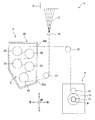
本発明にかかる紡糸延伸装置の実施形態について説明する。図1は、本実施形態の紡糸延伸装置を備える紡糸引取機を示す模式図である。図1に示すように、紡糸引取機1は、紡糸装置2から紡出された複数の糸Yを、紡糸延伸装置3で延伸した後、糸巻取装置4で巻き取る構成となっている。なお、以下では、各図に付した方向を参照しつつ説明を行う。
An embodiment of a spinning stretcher according to the present invention will be described. FIG. 1 is a schematic view showing a spinning take-up machine equipped with a spinning stretcher of this embodiment. As shown in FIG. 1, the spinning take-up machine 1 has a configuration in which a plurality of yarns Y spun from the
紡糸装置2は、ポリエステル等の溶融繊維材料を連続的に紡出することで、複数の糸Yを生成する。紡糸装置2から紡出された複数の糸Yは、油剤ガイド10によって油剤が付与された後、案内ローラ11を経て紡糸延伸装置3に送られる。紡糸延伸装置3は、複数の糸Yを延伸する装置であり、紡糸装置2の下方に配置されている。紡糸延伸装置3は、保温箱20の内部に複数のゴデットローラ31〜35が設けられた構成となっている。紡糸延伸装置3については、後で詳細に説明する。
The
紡糸延伸装置3で延伸された複数の糸Yは、案内ローラ12を経て糸巻取装置4に送られる。糸巻取装置4は、複数の糸Yを巻き取る装置であり、紡糸延伸装置3の下方に配置されている。糸巻取装置4は、ボビンホルダ13やコンタクトローラ14等を備えている。ボビンホルダ13は、図1の紙面奥行方向に延びる円筒形状を有し、図示しないモータによって回転駆動される。ボビンホルダ13には、その軸方向に複数のボビンBが並んだ状態で装着される。糸巻取装置4は、ボビンホルダ13を回転させることによって、複数のボビンBに複数の糸Yを同時に巻取り、複数のパッケージPを生産する。コンタクトローラ14は、複数のパッケージPの表面に接触して所定の接圧を付与し、パッケージPの形状を整える。
The plurality of yarns Y drawn by the
紡糸延伸装置3の詳細について説明する。紡糸延伸装置3は、保温箱20の内部空間Sに収容された複数(ここでは5つ)のゴデットローラ31〜35を有している。各ゴデットローラ31〜35は、不図示のモータによって回転駆動されるとともに、不図示のヒータを有する加熱ローラである。保温箱20の右側面部の下部には、複数の糸Yを保温箱20の内部に導入するための導入口20aが形成され、保温箱20の右側面部の上部には、複数の糸Yを保温箱20の外部に導出するための導出口20bが形成されている。導入口20aから導入された複数の糸Yは、下側のゴデットローラ31から順に巻き掛けられ、最終的に導出口20bから導出される。
Details of the spinning and drawing
ゴデットローラ31〜35は、片掛けで糸Yを巻き掛けられるように配置されている。下側3つのゴデットローラ31〜33は、複数の糸Yを延伸する前に予熱するための予熱ローラであり、それらのローラ表面温度は、糸Yのガラス転移点以上の温度(例えば80℃程度)に設定されている。一方、上側2つのゴデットローラ34、35は、延伸された複数の糸Yを熱セットするための調質ローラであり、それらのローラ表面温度は、下側3つのゴデットローラ31〜33のローラ表面温度よりも高い温度(例えば130〜140℃程度)に設定されている。また、上側2つのゴデットローラ34、35の糸送り速度は、下側3つのゴデットローラ31〜33よりも速くなっている。以下の説明においては、適宜、ゴデットローラ31〜33を「予熱ローラ」と称し、ゴデットローラ34、35を「調質ローラ」と称する。
The
導入口20aを介して保温箱20内に導入された複数の糸Yは、まず、予熱ローラ31〜33によって送られる間に延伸可能な温度まで予熱される。予熱された複数の糸Yは、予熱ローラ33と調質ローラ34との間の糸送り速度の差によって延伸される。さらに、複数の糸Yは、調質ローラ34、35によって送られる間にさらに高温に加熱されて、延伸された状態が熱セットされる。このようにして延伸された複数の糸Yは、導出口20bを介して保温箱20外に導出される。
The plurality of yarns Y introduced into the
ここで、紡糸延伸装置3において省エネを図るために、調質ローラ34、35付近の高温の空気を、予熱ローラ31〜33付近に送ることによって、予熱ローラ31〜33における電力消費量を低減することが考えられる。しかしそうすると、調質ローラ34、35付近の高温の空気に含まれるオイルミスト等の汚染物質が、空気とともに予熱ローラ31〜33付近に送られてしまい、予熱ローラ31〜33のローラ表面に固着するおそれがあった。
Here, in order to save energy in the spinning and drawing
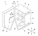
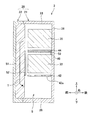
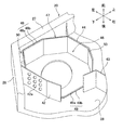
そこで、本実施形態の紡糸延伸装置3では、保温箱20の内面に熱伝導促進部を設けることで、予熱ローラ31〜33における電力消費量の低減を実現している。図2は、保温箱の開閉部を開いた状態における斜視図であり、図3は、保温箱の開閉部を閉じた状態における断面図である。より詳細には、図3は、予熱ローラ33および調質ローラ35の回転軸を含む鉛直面における断面図である。なお、図2においては、後述する整流部材41〜45および断熱部材47の図示を省略している。
Therefore, in the
図2に示すように、保温箱20は、ローラ31〜35を内部に収容する収容部21と、収容部21に対して不図示のヒンジ等を支点として回動自在な開閉部22とを有して構成される。収容部21は、天井部23、右側面部24、右下側面部25、左下側面部26、左側面部27および背面部28からなっており、背面部28からローラ31〜35が前方に突出している。
As shown in FIG. 2, the
開閉部22には、開閉部22を閉めた状態において、保温箱20の内部空間S側に開口している凹部22aが略全面にわたって形成されている。そして、保温箱20を構成する材料よりも熱伝導率の高い材料が凹部22aに充填されることで、熱伝導促進部51が構成されている。本実施形態では、保温箱20(収容部21および開閉部22)は構造体として機能するため、強度に優れたステンレスで構成されており、熱伝導促進部51は、伝熱性を優先するため、ステンレスよりも熱伝導率が高いアルミニウム合金で構成されている。また、図3に示すように、熱伝導促進部51は、開閉部22の凹部22aから若干突出し、ローラ31〜35の端面との距離が狭まるように設けられている。
The opening / closing
このような熱伝導促進部51を設けることで、調質ローラ34、35から発生した熱を、熱伝導促進部51を介した熱伝導によって、積極的に予熱ローラ31〜33側に移動させることができる(図3の矢印T参照)。その結果、予熱ローラ31〜33における電力消費量を低減できるものとなっている。
By providing such a heat
ところで、本実施形態のように、複数の予熱ローラ31〜33を配置した場合、予熱ローラ31〜33のうち最も糸走行方向下流側に配置され、延伸直前の糸Yを加熱する最終予熱ローラ33は、高温の調質ローラ34、35に近接することになる。このため、最終予熱ローラ33のローラ表面温度は、調質ローラ34、35の影響を受けやすく、設定温度以上に高温になってしまうことがある。最終予熱ローラ33の温度は、延伸時における糸Yの温度に及ぼす影響が大きいため、最終予熱ローラ33の温度を適切に制御できないと、糸Yを所定の品質に維持することができない。
By the way, when a plurality of preheating
そこで、本実施形態の紡糸延伸装置3では、熱伝導促進部51の表面のうち、最終予熱ローラ33の端面に対向する領域に前面断熱部52が設けられている。前面断熱部52は、図2に示すように、構造体としての金属板52aと、金属板52aのうち開閉部22側の面に塗布された断熱塗料52bとが積層された構成となっている。前面断熱部52は、熱伝導促進部51の表面に張り合わせる形態で設けられている。なお、前面断熱部52の熱伝導率は、少なくとも熱伝導促進部51よりも小さく、さらには開閉部22よりも小さいことが望ましい。
Therefore, in the
このような前面断熱部52を設けることで、調質ローラ34、35から発生した熱が、熱伝導促進部51内を予熱ローラ31〜33側に移動する過程において、最終予熱ローラ33の近傍で放熱されることを抑制することができる。前面断熱部52は、熱伝導促進部51の表面のうち、好ましくは最終予熱ローラ33の端面に対向する領域の全領域にわたって、さらに好ましくは、後述する最終予熱ローラ33の配設空間46(図4参照)に面する領域の全領域にわたって設けられているとよい。
By providing such a front
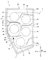
さらに、本実施形態の紡糸延伸装置3では、最終予熱ローラ33の温度上昇を抑制するため、前面断熱部52に加えて、側面断熱部48と背面断熱部49とが一体的に構成された断熱部材47と、整流部材44の最終予熱ローラ33側に取り付けられた断熱部53が設けられている。図4は、紡糸延伸装置3の内部構造を詳細に示す断面図であり、図5は、断熱部材47を示す斜視図である。なお、図5において、最終予熱ローラ33の図示は省略している。
Furthermore, in the
図1や図2では図示を省略したが、保温箱20の内部には、保温箱20内での空気の流れを整流するため、概ね糸Yの走行方向に沿うように、複数の整流部材41〜45が設けられている。このうち、予熱ローラ31と最終予熱ローラ33との間に配置された整流部材42、予熱ローラ32と調質ローラ34との間に配置された整流部材43の先端部、および最終予熱ローラ33と調質ローラ35との間に配置された整流部材44によって、最終予熱ローラ33が配設される配設空間46が概ね区画されている。そして、この配設空間46に面するように、断熱部材47が設けられている。
Although not shown in FIGS. 1 and 2, a plurality of rectifying
断熱部材47は、中央部に最終予熱ローラ33を配設するための開口が形成された多角形状の背面断熱部49と、背面断熱部49の周縁の一部から立設された側面断熱部48とを有する。側面断熱部48は、背面断熱部49の周縁の形状に合わせて、板材を折り曲げることで構成されている。
The
断熱部材47の側面断熱部48は、保温箱20の左下側面部26および左側面部27に概ね沿った形状となっている。側面断熱部48は、側面部26、27からわずかに離間しており、側面断熱部48と側面部26、27との間に空気層50が形成される。このような空気層50を設けることで、側面断熱部48による断熱効果を高めることができる。しかしながら、空気層50の層厚が広いと、対流による伝熱が大きくなり、断熱層としての機能を果たさなくなる。したがって、空気層50の層厚は、例えば30mm以下程度とするのが好ましい。一方、断熱部材47の背面断熱部49は、保温箱20の背面部28に当接させた状態で不図示のボルト等により固定されており、背面断熱部49と背面部28との間には、空気層は形成されていない。
The side
ここで、側面断熱部48は、構造体としての金属板48aと、金属板48aのうち側面部26、27側の面に塗布された断熱塗料48bとが積層された構成となっている。同様に、背面断熱部49も、構造体としての金属板49aと、金属板49aのうち背面部28側の面に塗布された断熱塗料49bとが積層された構成となっている。このような側面断熱部48および背面断熱部49を設けることで、高温の調質ローラ34、35からの熱が、保温箱20の側面部26、27や背面部28を介した熱伝導により、最終予熱ローラ33の配設空間46近傍に伝わっても、その熱が側面部26、27や背面部28から配設空間46に放熱されることを抑制できる。
Here, the side
さらに、本実施形態では、調質ローラ34、35の周囲に形成される高温空間54と、高温空間54に隣接する配設空間46との間に、断熱部53が設けられている。具体的には、断熱部53は、整流部材44の最終予熱ローラ33側に設けられており、高温空間54から配設空間46へ直接的に伝わる伝熱量を低減することができる。なお、断熱部53は、必ずしも整流部材44とは別に設ける必要はなく、整流部材44を熱伝導率の低い材料で構成することにより、整流部材44が断熱部としての機能も兼ね備えるようにしてもよい。また、断熱部48、49と同様に、断熱部53を、構造体としての金属板と、金属板の最終予熱ローラ33側の面に塗布された断熱塗料とによって構成してもよい。
Further, in the present embodiment, the
また、本実施形態では、最終予熱ローラ33の周りに配設された整流部材42〜44のうち、最終予熱ローラ33よりも導入口20a側に設けられた整流部材42に、複数の開口42aを形成してある。導入口20aから保温箱20内に流入した空気は、糸Yの走行に伴って生ずる随伴流とともに、整流部材42と導入口20aとの間に位置する予熱ローラ31の周面と、保温箱20の右下側面部25および左下側面部26の内面との間に形成される流路Fに沿って流れる。この流路Fの延長線上に、開口42aを設けることで、導入口20aから流入した比較的低温の空気が、開口42aを介して最終予熱ローラ33の配設空間46に供給され、最終予熱ローラ33の過度な昇温を防ぐことができる。
In the present embodiment, among the rectifying
(効果)
以上のように、本実施形態の紡糸延伸装置3においては、保温箱20の内面に、調質ローラ34、35の近傍領域から予熱ローラ31〜33の近傍領域にわたって、保温箱20を構成する材料よりも熱伝導率の高い熱伝導促進部51が設けられている。このため、高温の調質ローラ34、35から発生する熱が、熱伝導促進部51を介した熱伝導により、低温の予熱ローラ31〜33に伝えられる。このため、予熱ローラ31〜33の加熱に要する電力消費量を低減することができる。また、このように熱伝導を利用することで、高温の空気そのものを移動させずに、熱だけを予熱ローラ31〜33に伝えることができるので、汚染物質が空気とともに予熱ローラ31〜33付近に移動することを回避できる。したがって、本発明によれば、予熱ローラ31〜33の電力消費量を低減するとともに、予熱ローラ31〜33のローラ表面に汚染物質が付着することを防止することができる。
(effect)
As described above, in the spinning and drawing
また、本実施形態では、保温箱20は、予熱ローラ31〜33および調質ローラ34、35の端面に向かい合う開閉可能な開閉部22を有しており、開閉部22に熱伝導促進部51が設けられている。開閉部22は、一般的に保温箱20の側面部24〜27等よりも面積が広いため、開閉部22に熱伝導促進部51を設けることにより、熱伝導促進部51を広く確保することができる。このため、調質ローラ34、35から予熱ローラ31〜33への伝熱量を大きくしやすい。
Moreover, in this embodiment, the
また、本実施形態のように、複数の予熱ローラ31〜33が設けられている場合、最も糸走行方向下流側にある最終予熱ローラ33は、調質ローラ34、35に近接しているため、高温の調質ローラ34、35の影響を受けやすく、過度に温度が上昇しやすい。そこで、本実施形態のように、熱伝導促進部51の表面のうち最終予熱ローラ33の近傍領域に断熱部52を設けることで、熱伝導促進部51から最終予熱ローラ33への伝熱を抑制し、最終予熱ローラ33の温度上昇を抑制することができる。
Further, as in the present embodiment, when a plurality of preheating
また、本実施形態では、断熱部52は、金属板52aと断熱材52bとが積層された構成となっており、金属板52aが内部空間S側を向き、断熱材52bが熱伝導促進部51側を向くように配設されている。このため、例えば糸Yが切れた場合に、切れた糸Yが接触するのは断熱部52の金属板52a側であり、切れた糸Yによって断熱材52bが損傷を受けるといったことがなく、断熱部52の断熱機能が低下することを防止できる。
Moreover, in this embodiment, the
[他の実施形態]
以上、本発明の実施形態について説明したが、本発明を適用可能な形態は、上記実施形態に限られるものではなく、以下に例示するように、本発明の趣旨を逸脱しない範囲で適宜変更を加えることが可能である。
[Other Embodiments]
The embodiment of the present invention has been described above. However, the form to which the present invention can be applied is not limited to the above-described embodiment, and can be appropriately changed without departing from the spirit of the present invention, as exemplified below. It is possible to add.
例えば、上記実施形態においては、3つの予熱ローラ31〜33および2つの調質ローラ34、35を有する紡糸延伸装置3について説明した。しかしながら、各ローラの個数や配置は適宜変更が可能である。
For example, in the above-described embodiment, the spinning and drawing
また、上記実施形態では、開閉部22の略全面に熱伝導促進部51を設けるものとしたが、熱伝導促進部51を設ける部位や範囲は適宜変更が可能である。例えば、熱伝導促進部51を、予熱ローラ31〜33および調質ローラ34、35の軸方向に沿う側面部24〜27に設けるようにしてもよい。このように熱伝導促進部51を配置することで、保温箱20の側面部24〜27から予熱ローラ31〜33の周面へ輻射される熱を増加させることができ、予熱ローラ31〜33のローラ表面の温度を効果的に上昇させることができる。なお、上述のように、最終予熱ローラ33の温度上昇を抑制する必要がある場合には、熱伝導促進部51を最終予熱ローラ33から遠い右側面部24に設けることが有効である。
Moreover, in the said embodiment, although the heat
また、上記実施形態では、最終予熱ローラ33の近傍領域に断熱部52を設けるものとした。しかしながら、他に熱伝導促進部51からの放熱を抑えたい領域がある場合には、熱伝導促進部51の表面のうち当該領域に断熱部52を設けるようにしてもよい。
In the above embodiment, the
また、上記実施形態では、熱伝導促進部51としてステンレスよりも熱伝導率が高いアルミニウム合金を設けるものとした。しかしながら、熱伝導促進部51の具体的構成はこれに限定されず、保温箱20を構成する材料(これもステンレスに限定されない)よりも熱伝導率が高い材料であれば、他の材料を用いてもよい。例えば、熱伝導促進部51を、銅合金やC/Cコンポジット材等で構成することも可能である。
Moreover, in the said embodiment, the aluminum alloy whose heat conductivity is higher than stainless steel as the heat
また、上記実施形態では、保温箱20の側面部26、27、背面部28、開閉部22の内面に、それぞれ断熱部48、49、52を設けるものとし、整流部材44に断熱部53を設けるものとした。しかしながら、どの部位に断熱部を設けるかは、適宜変更が可能である。
Further, in the above embodiment, the
また、上記実施形態においては、背面断熱部49および前面断熱部52については、保温箱20の内面との間に、特に空気層を設けないものとしたが、スペーサを設けるなどして、断熱部49、52と保温箱20の内面との間に空気層を設けてもよい。
Moreover, in the said embodiment, about the back surface
また、上記実施形態においては、断熱部48、49、52を、金属板48a、49a、52aに、断熱材としての断熱塗料48b、49b、52aを塗布することで構成した。しかしながら、断熱部48、49、52の具体的な構成はこれに限定されず、金属板48a、49a、52aに、金属板48a、49a、52aよりも熱伝導率の低い部材を張り合わせたものなどでもよい。
Moreover, in the said embodiment, the
また、上記実施形態では、最終予熱ローラ33に導入口20aからの空気を供給する空気導入部として、整流部材42に複数の開口42aを形成した。しかしながら、空気導入部の構成はこれに限定されず、例えば、図4の流路Fの延長線上に整流部材42をそもそも配置しないようにしてもよい。
Further, in the above-described embodiment, the plurality of
3:紡糸延伸装置
20:保温箱
22:開閉部
22a:凹部
24〜27:側面部
28:背面部
31〜33:予熱ローラ
33:最終予熱ローラ
34、35:調質ローラ
51:熱伝導促進部
52:断熱部
52a:金属板
52b:断熱材
S:内部空間
Y:糸
3: Spinning and drawing device 20: Insulation box 22: Opening / closing
Claims (8)
延伸前の前記糸を加熱する予熱ローラと、
前記予熱ローラの糸走行方向下流側に配置されるとともに、前記予熱ローラよりも高温かつ高速に設定され、前記予熱ローラとの間で前記糸を延伸させる調質ローラと、
前記予熱ローラおよび前記調質ローラが収容される内部空間を有する保温箱と、
を備え、
前記保温箱の内面に、前記調質ローラの近傍領域から前記予熱ローラの近傍領域にわたって、前記保温箱を構成する材料よりも熱伝導率の高い熱伝導促進部が設けられていることを特徴とする紡糸延伸装置。 A spinning and drawing device for drawing a yarn spun from a spinning device,
A preheating roller for heating the yarn before drawing;
A tempering roller that is disposed on the downstream side of the preheating roller in the yarn traveling direction, is set at a higher temperature and higher speed than the preheating roller, and extends the yarn between the preheating roller,
A heat insulation box having an internal space in which the preheating roller and the tempering roller are accommodated;
With
A heat conduction promoting portion having a higher thermal conductivity than a material constituting the heat retaining box is provided on the inner surface of the heat retaining box from a region near the tempering roller to a region near the preheating roller. Spinning and drawing device.
前記熱伝導促進部の表面のうち、前記複数の予熱ローラのうち最も糸走行方向下流側にある最終予熱ローラの近傍領域に、前記断熱部が設けられている請求項6または7に記載の紡糸延伸装置。 A plurality of the preheating rollers are provided,
The spinning according to claim 6 or 7, wherein, in the surface of the heat conduction promoting portion, the heat insulating portion is provided in a region near the final preheating roller that is most downstream in the yarn running direction among the plurality of preheating rollers. Stretching device.
Priority Applications (3)
| Application Number | Priority Date | Filing Date | Title |
|---|---|---|---|
| JP2015044252A JP6446292B2 (en) | 2015-03-06 | 2015-03-06 | Spinning and drawing equipment |
| EP16158440.4A EP3064622B1 (en) | 2015-03-06 | 2016-03-03 | Spun yarn drawing apparatus |
| CN201610121478.9A CN105937061B (en) | 2015-03-06 | 2016-03-03 | Spin-drawing device |
Applications Claiming Priority (1)
| Application Number | Priority Date | Filing Date | Title |
|---|---|---|---|
| JP2015044252A JP6446292B2 (en) | 2015-03-06 | 2015-03-06 | Spinning and drawing equipment |
Publications (2)
| Publication Number | Publication Date |
|---|---|
| JP2016164315A JP2016164315A (en) | 2016-09-08 |
| JP6446292B2 true JP6446292B2 (en) | 2018-12-26 |
Family
ID=55521512
Family Applications (1)
| Application Number | Title | Priority Date | Filing Date |
|---|---|---|---|
| JP2015044252A Active JP6446292B2 (en) | 2015-03-06 | 2015-03-06 | Spinning and drawing equipment |
Country Status (3)
| Country | Link |
|---|---|
| EP (1) | EP3064622B1 (en) |
| JP (1) | JP6446292B2 (en) |
| CN (1) | CN105937061B (en) |
Families Citing this family (4)
| Publication number | Priority date | Publication date | Assignee | Title |
|---|---|---|---|---|
| JP6829043B2 (en) * | 2016-10-20 | 2021-02-10 | Tmtマシナリー株式会社 | Spinning equipment and thread hooking robot |
| CN110846727B (en) * | 2019-12-26 | 2025-06-13 | 苏州金纬化纤装备有限公司 | Automatic induction spinning and drawing constant temperature box |
| JP7586766B2 (en) * | 2020-06-24 | 2024-11-19 | Tmtマシナリー株式会社 | Spinning and drawing equipment |
| EP4411036A4 (en) * | 2021-09-30 | 2026-04-22 | Beijing Chonglee Machinery Eng Co Ltd | FIBER SPINNING STRETCHING AND WINDING DEVICE AND COMBINED MACHINE FOR THE POLYLTIC ACID INDUSTRY |
Family Cites Families (10)
| Publication number | Priority date | Publication date | Assignee | Title |
|---|---|---|---|---|
| AU2002235295A1 (en) * | 2002-01-03 | 2003-07-30 | Invista Technologies S.A.R.L. | Yarn making process and apparatus |
| CN2795239Y (en) * | 2004-09-16 | 2006-07-12 | 张广聚 | Electric heater for chemical fiber spinning production apparatus |
| CN201686776U (en) * | 2010-04-23 | 2010-12-29 | 桐乡市中驰化纤有限公司 | Attemperator of FDY heat roller box |
| JP5645594B2 (en) * | 2010-10-21 | 2014-12-24 | Tmtマシナリー株式会社 | Yarn heating device |
| JP5580242B2 (en) * | 2011-03-31 | 2014-08-27 | Tmtマシナリー株式会社 | Yarn heating device |
| JP5735849B2 (en) * | 2011-04-26 | 2015-06-17 | Tmtマシナリー株式会社 | Yarn heating device |
| JP5977153B2 (en) * | 2012-11-22 | 2016-08-24 | Tmtマシナリー株式会社 | Spinning and winding equipment |
| JP5968766B2 (en) * | 2012-11-22 | 2016-08-10 | Tmtマシナリー株式会社 | Spinning and winding equipment |
| JP6258610B2 (en) * | 2012-06-27 | 2018-01-10 | Tmtマシナリー株式会社 | Spinning and drawing equipment |
| JP6088948B2 (en) * | 2013-09-12 | 2017-03-01 | Tmtマシナリー株式会社 | Heat insulation box |
-
2015
- 2015-03-06 JP JP2015044252A patent/JP6446292B2/en active Active
-
2016
- 2016-03-03 EP EP16158440.4A patent/EP3064622B1/en active Active
- 2016-03-03 CN CN201610121478.9A patent/CN105937061B/en active Active
Also Published As
| Publication number | Publication date |
|---|---|
| EP3064622B1 (en) | 2018-05-09 |
| EP3064622A1 (en) | 2016-09-07 |
| JP2016164315A (en) | 2016-09-08 |
| CN105937061B (en) | 2019-06-14 |
| CN105937061A (en) | 2016-09-14 |
Similar Documents
| Publication | Publication Date | Title |
|---|---|---|
| JP6532707B2 (en) | Spinning and drawing machine | |
| JP6446292B2 (en) | Spinning and drawing equipment | |
| JP5735849B2 (en) | Yarn heating device | |
| EP2415915B1 (en) | Yarn heating apparatus | |
| JP6258610B2 (en) | Spinning and drawing equipment | |
| JP5968766B2 (en) | Spinning and winding equipment | |
| TWI597393B (en) | Thermal insulation box | |
| EP2677069B1 (en) | Spun yarn drawing apparatus | |
| JP6668163B2 (en) | Yarn heating device | |
| EP3438588B1 (en) | Low-temperature drying apparatus | |
| JP5977153B2 (en) | Spinning and winding equipment | |
| EP3288339A1 (en) | Induction heating roller | |
| JP7586766B2 (en) | Spinning and drawing equipment | |
| EP4198176A2 (en) | Spinning apparatus | |
| EP3758444B1 (en) | Induction heating roller and spun yarn take-up machine | |
| EP3700301B1 (en) | Induction heating roller and spun yarn drawing device | |
| EP3700300B1 (en) | Induction heating roller and spun yarn drawing device | |
| US10752463B2 (en) | Changing element for a spinning machine, and spinning machine equipped with said changing element | |
| EP4386119A2 (en) | Spun yarn drawing apparatus | |
| EP4382648A1 (en) | Yarn heater and false-twist texturing machine |
Legal Events
| Date | Code | Title | Description |
|---|---|---|---|
| A621 | Written request for application examination |
Free format text: JAPANESE INTERMEDIATE CODE: A621 Effective date: 20171113 |
|
| A977 | Report on retrieval |
Free format text: JAPANESE INTERMEDIATE CODE: A971007 Effective date: 20181115 |
|
| TRDD | Decision of grant or rejection written | ||
| A01 | Written decision to grant a patent or to grant a registration (utility model) |
Free format text: JAPANESE INTERMEDIATE CODE: A01 Effective date: 20181120 |
|
| A61 | First payment of annual fees (during grant procedure) |
Free format text: JAPANESE INTERMEDIATE CODE: A61 Effective date: 20181203 |
|
| R150 | Certificate of patent or registration of utility model |
Ref document number: 6446292 Country of ref document: JP Free format text: JAPANESE INTERMEDIATE CODE: R150 |
|
| R250 | Receipt of annual fees |
Free format text: JAPANESE INTERMEDIATE CODE: R250 |
|
| R250 | Receipt of annual fees |
Free format text: JAPANESE INTERMEDIATE CODE: R250 |
|
| R250 | Receipt of annual fees |
Free format text: JAPANESE INTERMEDIATE CODE: R250 |
|
| R250 | Receipt of annual fees |
Free format text: JAPANESE INTERMEDIATE CODE: R250 |
|
| R250 | Receipt of annual fees |
Free format text: JAPANESE INTERMEDIATE CODE: R250 |