EP3927140B1 - Hin- und hergehende mäheinheit, system und verfahren - Google Patents
Hin- und hergehende mäheinheit, system und verfahren Download PDFInfo
- Publication number
- EP3927140B1 EP3927140B1 EP19706952.9A EP19706952A EP3927140B1 EP 3927140 B1 EP3927140 B1 EP 3927140B1 EP 19706952 A EP19706952 A EP 19706952A EP 3927140 B1 EP3927140 B1 EP 3927140B1
- Authority
- EP
- European Patent Office
- Prior art keywords
- gear
- mower unit
- reciprocating mower
- shaft
- reciprocating
- Prior art date
- Legal status (The legal status is an assumption and is not a legal conclusion. Google has not performed a legal analysis and makes no representation as to the accuracy of the status listed.)
- Active
Links
Images


Classifications
-
- A—HUMAN NECESSITIES
- A01—AGRICULTURE; FORESTRY; ANIMAL HUSBANDRY; HUNTING; TRAPPING; FISHING
- A01D—HARVESTING; MOWING
- A01D34/00—Mowers; Mowing apparatus of harvesters
- A01D34/01—Mowers; Mowing apparatus of harvesters characterised by features relating to the type of cutting apparatus
- A01D34/404—Mowers; Mowing apparatus of harvesters characterised by features relating to the type of cutting apparatus having cutters driven to oscillate in a horizontal plane
-
- A—HUMAN NECESSITIES
- A01—AGRICULTURE; FORESTRY; ANIMAL HUSBANDRY; HUNTING; TRAPPING; FISHING
- A01D—HARVESTING; MOWING
- A01D34/00—Mowers; Mowing apparatus of harvesters
- A01D34/01—Mowers; Mowing apparatus of harvesters characterised by features relating to the type of cutting apparatus
- A01D34/412—Mowers; Mowing apparatus of harvesters characterised by features relating to the type of cutting apparatus having rotating cutters
- A01D34/63—Mowers; Mowing apparatus of harvesters characterised by features relating to the type of cutting apparatus having rotating cutters having cutters rotating about a vertical axis
- A01D34/76—Driving mechanisms for the cutters
-
- A—HUMAN NECESSITIES
- A01—AGRICULTURE; FORESTRY; ANIMAL HUSBANDRY; HUNTING; TRAPPING; FISHING
- A01D—HARVESTING; MOWING
- A01D34/00—Mowers; Mowing apparatus of harvesters
- A01D34/835—Mowers; Mowing apparatus of harvesters specially adapted for particular purposes
- A01D34/90—Mowers; Mowing apparatus of harvesters specially adapted for particular purposes for carrying by the operator
Definitions
- the present invention relates to a reciprocating mower unit, a vegetation cutter system comprising such a reciprocating mower unit, and methods of operating a reciprocating mower unit.
- US4998401A discloses a reciprocating mower oscillating a pair of mowing blades in mutual anti-phase about a common oscillation axis. Such a mower facilitates convenient mowing of soft grass as well as small shrubs with a very low risk of kicking off pebble-stones. Similar reciprocating mowers are disclosed in each of EP 0 399 503 A2 , EP 0 390 087 A1 , EP 0 384 471 A1 , and EP 0 337 428 A1 . There is however a need for a more ergonomic and user-friendly mower.
- a reciprocating mower unit configured to be driven by a drive unit via a transmission shaft arranged within a transmission tube
- the reciprocating mower unit comprising: a housing; a reduction gear arranged within the housing, the reduction gear being configured to receive an input rotary motion from the transmission shaft at a first, relatively higher, rotation speed, and deliver an output rotary motion to a gear output shaft at a second, relatively lower, rotation speed; a crank mechanism arranged within the housing, the crank mechanism being configured to convert the output rotary motion of the gear output shaft to an oscillating motion of a pair of mowing blades oscillating in mutual anti-phase about a common oscillation axis; and an input shaft for receiving said input rotary motion from the transmission shaft, wherein the input shaft is provided with a coupling interface for releasably coupling the input shaft to the transmission shaft.
- Such a reciprocating mower unit permits coupling and de-coupling of the reciprocating mower unit to/from the transmission shaft, which allows connecting the reciprocating mower unit to different drive units, and vice versa. Thereby, the versatility of the reciprocating mower unit as well as the drive unit is increased.
- the coupling interface may comprise splines for axially sliding into rotational engagement with mating splines of the transmission shaft.
- One of the input shaft and the transmission shaft may comprise a socket provided with inner splines, whereas the other of the input shaft and the transmission shaft may be provided with outer splines.
- the housing may comprise a clamping arrangement for clamping the housing to the transmission tube.
- a vegetation cutter system comprising: a drive unit comprising a motor and a transmission shaft arranged within a transmission tube; a reciprocating mower unit as defined above; and a clearing saw unit configured to rotate a clearing saw blade, wherein the reciprocating mower unit and the clearing saw unit are configured to be alternatingly connected to the transmission shaft.
- a reciprocating mower unit configured to be driven by a drive unit via a transmission shaft arranged within a transmission tube
- the reciprocating mower unit comprising: a housing; a reduction gear arranged within the housing, the reduction gear being configured to receive an input rotary motion from the transmission shaft at a first, relatively higher, rotation speed, and deliver an output rotary motion to a gear output shaft at a second, relatively lower, rotation speed; and a crank mechanism arranged within the housing, the crank mechanism being configured to convert the output rotary motion of the gear output shaft to an oscillating motion of a pair of mowing blades oscillating in mutual anti-phase about a common oscillation axis
- the reduction gear is a two-stage reduction gear comprising a first gear connected to corotate with the input shaft, a second gear in mesh with the first gear, a third gear connected to corotate with the second gear, and a fourth gear configured to co-rotate with
- Such a two-stage reduction gear permits obtaining a high reduction ratio with a compact volume in the reciprocating mower unit, which reduces the need for any reduction gear in the drive unit. Thereby, the manufacturing cost of the drive unit may be reduced, since the same type of drive unit may be used for e.g. rotary clearing saws.
- the reciprocating mower unit is provided with a coupling interface as defined hereinabove, a modular system may be obtained, allowing changing between rotary and reciprocating mower units using the same drive unit.
- the drive unit of such a modular system is entirely free from any reduction gear, such that the transmission shaft is rotated at the rotary speed of the motor.
- the first and second gears may be bevel gears.
- the rotation axis of the first gear may be inclined relative to the common oscillation axis by an inclination angle, which permits connecting to an inclined transmission shaft.
- the inclination angle may be between 25° and 65°, or between 45° and 60°.
- the first gear may have 7-14 teeth; the second gear may have 20-30 teeth; the third gear may have 11-19 teeth, and the fourth gear may have 26-40 teeth.
- a reciprocating mower unit configured to be driven by a drive unit via a transmission shaft arranged within a transmission tube
- the reciprocating mower unit comprising: a housing; a reduction gear arranged within the housing, the reduction gear being configured to receive an input rotary motion from the transmission shaft at a first, relatively higher, rotation speed, and deliver an output rotary motion to a gear output shaft at a second, relatively lower, rotation speed; and a crank mechanism arranged within the housing, the crank mechanism being configured to convert the output rotary motion of the gear output shaft to an oscillating motion of a pair of mowing blades oscillating in mutual anti-phase about a common oscillation axis, the crank mechanism comprising, for each of the mowing blades, a respective four-bar linkage configured to oscillate the respective blade in response to rotation of the gear output shaft, each of the four-bar linkages comprising a fixed link between a rotation axis of the gear output shaft
- the link ratio between the input link and the fixed link is at least 1:13.
- the link ratio may, according to a typical example, be between 1:13 and 1:25.
- a typical length of the input link may, for example, be between 1,5 mm and 3 mm.
- a typical length of the fixed link may, for example, exceed 31 mm.
- the fixed link may be shorter than about 50 mm.
- the reciprocating mower unit may be provided with a coupling interface and/or a two-stage reduction gear as defined hereinabove.
- the reciprocating mower unit may have a link ratio between the input link and the coupler link of at least 1:8. It has been found that using such a link ratio, a relatively low level of vibrations of the tool may be obtained in combination with a compact and efficient reciprocating mower unit, resulting in a more ergonomic reciprocating mower unit.
- the link ratio between the input link and the coupler link is between 1:9 and 1:14.
- a typical length of the coupler link may, for example, be between 19 mm and 29 mm.
- a typical length of the output link may, for example, be between 22 mm and 29 mm.
- a reciprocating mower unit configured to be driven by a drive unit via a transmission shaft arranged within a transmission tube
- the reciprocating mower unit comprising: a housing; a reduction gear arranged within the housing, the reduction gear being configured to receive an input rotary motion from the transmission shaft at a first, relatively higher, rotation speed, and deliver an output rotary motion to a gear output shaft at a second, relatively lower, rotation speed; and a crank mechanism arranged within the housing, the crank mechanism being configured to convert the output rotary motion of the gear output shaft to an oscillating motion of a pair of mowing blades oscillating in mutual anti-phase about a common oscillation axis, wherein the crank mechanism is configured to oscillate each respective mower blade about the common oscillation axis at an oscillation angle of less than 15°.
- the reciprocating mower unit may be provided with a coupling interface and/or a two-stage reduction gear and/or a four-bar linkage as defined hereinabove.
- a reciprocating mower unit configured to be driven by a drive unit via a transmission shaft arranged within a transmission tube
- the reciprocating mower unit comprising: a housing; a reduction gear arranged within the housing, the reduction gear being configured to receive an input rotary motion from the transmission shaft at a first, relatively higher, rotation speed, and deliver an output rotary motion to a gear output shaft at a second, relatively lower, rotation speed; a crank mechanism arranged within the housing, the crank mechanism being configured to convert the output rotary motion of the gear output shaft to an oscillating motion of a pair of mowing blades oscillating in mutual anti-phase about a common oscillation axis; and a grounding body defining a lowermost face for resting against the ground when the reciprocating mower unit is in use, wherein the grounding body is rotationally decoupled, with regard to turning about the common oscillation axis, from each mowing blade of said pair of mowing
- the reciprocating mower unit may be provided with a coupling interface and/or a two-stage reduction gear and/or a four-bar linkage and/or an oscillation angle as defined hereinabove.
- the grounding body may be rotationally decoupled also from the housing.
- the grounding body may have a circular outer shape, as seen along the common oscillation axis.
- the grounding body may be made of plastic.
- the grounding body may be axially carried by a blade reciprocation shaft.
- the grounding body may be axially held through a central opening of the grounding body between an upper axial stop and a lower axial stop, wherein an axial distance between the upper and lower axial stops exceeds the thickness of the grounding body adjacent the central aperture.
- the upper axial stop may be defined by a downwards facing shoulder of the mowing blade reciprocation shaft.
- the lower axial stop may be defined by a fastening arrangement in abutment with a lower shoulder of the mowing blade reciprocation shaft.
- the fastening arrangement may comprise, for example, a threaded element, such as a screw or a nut, holding a washer tightly into abutment with the lower axial shoulder.
- the central opening of the grounding body may be sufficiently larger than e.g any blade reciprocation shaft penetrating therethrough to allow free rotation of the grounding body relative to the blade reciprocation shaft.
- a method of operating a reciprocating mower unit comprising: driving a pair of mowing blades to oscillate in a guided mutual anti-phase motion about a common oscillation axis; and allowing a grounding body, axially held by the reciprocating mower unit at a bottom face thereof, to remain stationary.
- a method of operating a reciprocating mower comprising: operating a motor of a drive unit at a rotation speed of more than 8000 revolutions per minute; operating a transmission shaft having a length of at least 1 metre at the rotation speed of the motor; driving a first reduction gear step with an output rotary motion of the transmission shaft; driving a second reduction gear step with an output rotary motion of the first reduction gear step; and converting output rotary motion of the second reduction gear step to an oscillating motion of a pair of mowing blades.
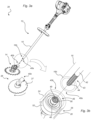
- Fig. 1 illustrates a handheld reciprocating mower 10 comprising a drive unit 12 and a reciprocating mower unit 14.
- the drive unit 12 comprises a transmission tube 16, and a motor 18 attached to a first end 16a of the transmission tube 16.
- the motor 18, which is configured to drive the reciprocating mower unit 14 via a transmission shaft (not illustrated) inside the transmission tube 16, may be e.g. an internal combustion engine or an electric motor.
- the drive unit is further provided with a pair of handles 20a, 20b for holding the reciprocating mower 10, and a trigger 22 for controlling a rotary speed of the motor 18, which in the case of an internal combustion engine is typically operated at a speed exceeding 8000 revolutions per minute (rpm).
- the reciprocating mower unit 14 is attached to a second end 16b of the transmission tube 16, opposite the first end 16a, such that an operator standing in an upright position, and holding the reciprocating mower 10 by the two handles 20a, 20b, may conveniently position the reciprocating mower unit 14 close to the ground and at a safe distance from his/her feet, for mowing e.g. grass and other vegetation.
- the transmission tube typically has a length exceeding about 1 metre.
- the reciprocating mower unit 14 comprises a housing 24 provided with a clamping arrangement 26 for clamping the housing 24 onto the transmission tube 16 ( Fig. 1 ).
- the clamping arrangement comprises a slit 28 in the housing 24, and a clamping screw 30 configured to press the slit 28 together.
- a crank mechanism (not illustrated) is arranged within the housing 24 underneath a top cover 25; the crank mechanism is configured to oscillate a pair of mowing blades 32a, 32b in mutual anti-phase about a common oscillation axis A1.
- the crank mechanism is configured to oscillate a first, lower mowing blade 32a of the pair of mowing blades between end positions defined by a first oscillation angle ⁇ 1 , and a second, upper mowing blade 32b of the pair of mowing blades between end positions defined by a second oscillation angle ⁇ 2 .
- the oscillation angle approximately corresponds to half the cutting tooth pitch P, i.e.
- each cutting tooth 34b of the upper mowing blade 32b alternatingly overlaps with two adjacent cutting teeth 34a of the lower mowing blade 32a, and vice versa, so as to shear off vegetation caught in the gap 36 therebetween.
- Fig. 3a illustrates the drive unit 12, the reciprocating mower unit 14, and a clearing saw unit 38.
- the drive unit 12 comprises, at the second end 16b of the transmission tube 16, a cutter unit interface 40a, and each of the reciprocating mower unit 14 and the clearing saw unit 38 comprises a respective drive unit interface 40b configured to mate with the cutter unit interface 40a of the drive unit 12.
- the drive unit 12, the reciprocating mower unit 14, and the clearing saw unit 38 make up a modular vegetation cutter system 39 allowing the reciprocating mower unit 14 and the clearing saw unit 38 to be alternatingly connected to the drive unit 12.
- the reciprocating mower unit 14 may be well suited for grass and small shrubs, in particular in situations where ricocheting pebbles may cause damage
- the rotary clearing saw unit 38 configured to rotating a circular clearing saw blade 37 at a high rotary speed, may be better suited for thicker shrubs and in situations where a higher cutting speed is desired. Thanks to the modular system 39, both alternatives may be available to the operator at a low weight and volume.
- Fig. 3b illustrates the cutter unit interface 40a of the drive unit 12 and the drive unit interface 40b of the reciprocating mower unit 14 in greater detail.
- the drive unit interface 40b of the clearing saw unit 38 may be identical to that of the reciprocating mower unit 14.
- the transmission shaft 42 is arranged inside the transmission tube 16, and is connected to be rotated by the motor 18 ( Fig. 1 ) of the drive unit 12.
- a free end 43 of the transmission shaft 42 is provided with outer splines 44 extending axially along the transmission shaft 42.
- the drive unit interface 40b comprises a transmission tube socket 46 for matingly receiving the free second end 16b of the transmission tube 16, and the clamping arrangement 26 allows decreasing the width of the slit 28 in the housing 24 such that the transmission tube 16 is firmly clamped in the transmission tube socket 46 of the housing 24.
- the drive unit interface 40b further comprises an input shaft 48 having a transmission shaft socket 49 provided with inner splines 50, for receiving the splined end 44 of the transmission shaft 42.
- a bearing arrangement 52 radially supports the input shaft 48 within the housing 24.
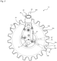
- Fig. 4a illustrates the housing 24 of the reciprocating mower unit 14 ( Fig. 1 ) with its cover 25 ( Fig. 2 ) removed, revealing a reduction gear 54 and a crank mechanism 56.
- the reduction gear 54 is configured to reduce the rotary speed delivered by the input shaft 48 ( fig. 3b ) to a lowered rotary speed of a gear output shaft 58, which drives the crank mechanism 56 for reciprocating the blades 32a, 32b ( Fig. 2 ).
- the gear output shaft 58 is configured to rotate about a gear output shaft rotation axis A2, and thereby rotate a first, upper, input crank, configured as a first, upper, crankpin 60a formed on the gear output shaft 58.
- the upper input crankpin 60a defines the input link of a first, upper, four-bar linkage, comprising the upper input crankpin 60a, an upper coupler link 62a, and an upper output crank 64a which is configured to reciprocate about the common oscillation axis A1 in response to rotating the upper input crankpin 60a about the gear output shaft rotation axis A2.
- the upper coupler link 62a is pivotally coupled to the upper input crankpin 60a and an upper output crankpin 66a of the output crank 64a, but otherwise floating.
- the fourth link of the upper four-bar linkage is defined by the fixed link between the gear output shaft rotation axis A2 and the common oscillation axis A.
- the fixed link is physically represented by the housing 24, which holds the gear output shaft rotation axis A2 and the common oscillation axis A1 in fixed relationship with each other.
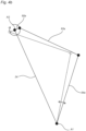
- Fig. 4b schematically illustrates the operation of the upper four-bar linkage 56.
- the four-bar linkage is illustrated in two positions, one of which is drawn in broken lines.
- the rotation of the input link 60a about the gear output shaft rotation axis A2 moves the coupler link 62a, which in turn pivots the output link 64a about the common oscillation axis A1 in a reciprocating manner.
- the fixed link 24 does not move.
- the coupler link 62a has a length of about 23 mm (i.e. the distance between the pivot axes is about 23 mm)
- the output link 64a has a length of about 25 mm
- the fixed link 24 has a length of about 37 mm.
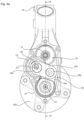
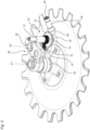
- Fig. 5 illustrates the reduction gear 54 and the crank mechanism 56 with the housing 24 ( Fig. 4a ) removed.
- the reduction gear 54 is a two-stage reduction gear comprising a first gear 68 attached to the input shaft 48, a second gear 70 attached to an intermediate shaft 72 and in mesh with the first gear 68, a third gear 74 attached to the intermediate shaft 72 to co-rotate with the second gear 70, and a fourth gear 76 attached to the gear output shaft 58 and in mesh with the third gear.
- the first and second gears 68, 70 are bevel gears; in the view of Fig. 5 , they are illustrated without teeth for ease of illustration.
- the first gear 68 has 11 teeth; the second gear 70 has 26 teeth; the third gear 74 has 15 teeth; and the fourth gear 76 has 33 teeth.
- first reduction in rotary speed at the engagement between the first and second gears 68, 70 defining a first stage of said two-stage reduction gear
- second reduction in rotary speed at the engagement between the third and fourth gears 74, 76 defining a second stage of said two-stage reduction gear.
- Upper and lower ends of the intermediate shaft 72 and the gear output shaft 58 are journaled in bearings 78, even though only the lower bearings are illustrated in the view of Fig. 5.
- Fig. 5 also illustrates the first, upper four-bar mechanism of the crank mechanism 56 along with a second, lower, four-bar mechanism which, however, is better illustrated in the exploded view of Fig. 6 .
- the second, lower, four-bar mechanism is also driven by the gear output shaft 58.
- An input crank configured as a second, lower crankpin 60b formed on the gear output shaft 58, defines the input link of the second, lower, four-bar linkage.
- the lower crankpin 60b is out of phase with the upper crankpin 60a, with regard to rotation about the gear output shaft rotation axis A2, by 180°.
- the lower four-bar linkage comprises the lower input crankpin 60b, a lower coupler link 62b, and a lower output crank 64b which is configured to reciprocate about the common oscillation axis A1 in response to rotating the lower input crankpin 60b about the gear output shaft rotation axis A2.
- the lower coupler link 62b is pivotally coupled to the lower input crankpin 60b and a lower output crankpin 66b of the lower output crank 64b, but otherwise floating.
- the fourth link of the lower four-bar linkage is, similar to the upper four-bar linkage, defined by the fixed link between the gear output shaft rotation axis A2 and the common oscillation axis A1, and is physically represented by the housing 24.
- the lower output crank 64b is connected to an outer blade reciprocation shaft 80b via splines, to reciprocate the outer blade reciprocation shaft 80b about the common oscillation axis A1.
- An upper blade carrier 82b is fixedly connected to a bottom end of the outer blade reciprocation shaft 80b.
- the upper output crank 64a is connected to an inner blade reciprocation shaft 80a via splines, to reciprocate the inner blade reciprocation shaft 80a about the common oscillation axis A1 in anti-phase with the outer blade reciprocation shaft 80b.
- a lower blade carrier 82a is fixedly connected to a bottom end of the inner blade reciprocation shaft 80a.
- the inner and outer blade reciprocation shafts 80a, 80b are concentric, and the inner blade reciprocation shaft 80a extends axially, from the lower blade carrier 82a, through the outer reciprocation shaft 80b and the lower output crank 64b, to engage with the splines of the upper output crank 62a.
- Each of the lower and upper blade carriers 82a, 82b holds a respective mowing blade 32a, 32b ( Fig. 2 ).
- the section of Fig. 7 illustrates the various components of the reduction gear 54 and the crank mechanism 56. Even though the gear output shaft 58 is not visible in the section, its rotation axis A2 is indicated in line with the centre of the fourth gear 76.
- the input shaft 48 is inclined in relation to the common oscillation axis A1 of the gear output shaft by an inclination angle ⁇ 3 of about 55°, to provide for holding the transmission tube 16 ( Fig. 1 ) at a convenient angle, with the blades 32a, 32b horizontal above the ground.
- the section of view 7 also illustrates a grounding body 84 for resting against the ground when the reciprocating mower unit 14 is in use.
- Fig. 8 illustrates the grounding body 84 in perspective; it has a circular outer shape, as seen along the common oscillation axis A1. and is provided with a circular central aperture 86 for receiving a screw 88.
- a washer 90 forms a lower axial stop for the grounding body 84.
- the screw 88 engages with an inner thread of the inner blade reciprocation shaft 80a such that the screw 88 and the inner blade reciprocation shaft 80a are rigidly connected.
- the screw 88 tightly holds the washer 90 against a lower axial end 92 of the inner blade reciprocation shaft 80a, whereas the bottom face of the lower blade carrier 82a, which is integrally formed with the inner blade reciprocation shaft 80a, defines an upper axial stop of the grounding body 84.
- the axial distance between the upper and lower axial stops exceeds the thickness of the grounding body adjacent the central aperture 86.
Landscapes
- Life Sciences & Earth Sciences (AREA)
- Environmental Sciences (AREA)
- Harvester Elements (AREA)
Claims (17)
- Hin- und herbewegbare Mäheinheit (14), die konfiguriert ist, um durch eine Antriebseinheit (12) über eine Übertragungswelle (42) angetrieben zu werden, die innerhalb eines Übertragungsrohr (16) angeordnet ist, die hin- und herbewegbare Mäheinheit (14) umfassend:ein Gehäuse (24);ein Untersetzungsgetriebe (54), das innerhalb des Gehäuses (24) angeordnet ist, wobei das Untersetzungsgetriebe (54) konfiguriert ist, um eine Eingangsdrehbewegung von der Getriebewelle (42) mit einer ersten, relativ höheren Drehgeschwindigkeit zu empfangen und eine Ausgangsdrehbewegung mit einer zweiten, relativ niedrigeren Drehgeschwindigkeit an eine Getriebeausgangswelle (58) abzugeben; undein Kurbelgetriebe (56), das innerhalb des Gehäuses angeordnet ist, wobei das Kurbelgetriebe (56) konfiguriert ist, um die Ausgangsdrehbewegung der Getriebeausgangswelle (58) in eine oszillierende Bewegung eines Paars von Mähklingen (32a, 32b) umzuwandeln, die in gegenseitiger Gegenphase um eine gemeinsame Oszillationsachse (A1) oszillieren, wobei die hin- und herbewegbare Mäheinheit (14) dadurch gekennzeichnet ist, dass sie eine Eingangswelle (48) zum Aufnehmen der Eingangsdrehbewegung von der Getriebewelle (42) umfasst, wobei die Eingangswelle (48) mit einer Kupplungsschnittstelle (49) zum lösbaren Kuppeln der Eingangswelle (48) mit der Getriebewelle (42) versehen ist.
- Hin- und herbewegbare Mäheinheit nach Anspruch 1, wobei die Kupplungsschnittstelle (49) Keilwellenprofile (50) zum axialen Gleiten in Dreheingriff mit Gegenkeilwellenprofilen (44) der Übertragungswelle (42) umfasst.
- Hin- und herbewegbare Mäheinheit nach einem der vorstehenden Ansprüche, wobei das Gehäuse (24) eine Klemmanordnung (26) zum Festklemmen des Gehäuses (24) an dem Übertragungsrohr (16) umfasst.
- Hin- und herbewegbare Mäheinheit nach einem der vorstehenden Ansprüche, wobei das Untersetzungsgetriebe (54) ein zweistufiges Untersetzungsgetriebe ist, umfassend ein erstes Getrieberad (68), das verbunden ist, um sich mit der Eingangswelle (48) mitzudrehen, ein zweites Getrieberad (70), das mit dem ersten Getrieberad (68) in Eingriff steht, ein drittes Getrieberad (74), das verbunden ist, um sich mit dem zweiten Getrieberad (70) mitzudrehen, und ein viertes Getrieberad (76), das konfiguriert ist, um sich mit einer Kurbel (60a; 60b) des Kurbelgetriebes (56) mitzudrehen, wobei das vierte Getrieberad (76) mit dem dritten Getrieberad (74) in Eingriff steht, wobei das erste Getrieberad (68) eine erste Anzahl von Zähnen aufweist, das zweite Getrieberad (70) eine zweite Anzahl von Zähnen aufweist, das dritte Getrieberad (74) eine dritte Anzahl von Zähnen aufweist und das vierte Getrieberad (76) eine vierte Anzahl von Zähnen aufweist, wobei das zweite Getrieberad (70) mehr Zähne als das erste Getrieberad (68) aufweist und das vierte Getrieberad (76) mehr Zähne als das dritte Getrieberad (74) aufweist.
- Hin- und herbewegbare Mäheinheit nach Anspruch 4, wobei das erste Getrieberad (68) 7-14 Zähne aufweist; das zweite Getrieberad (70) 20-30 Zähne aufweist; das dritte Getrieberad (74) 11-19 Zähne aufweist und das vierte Getrieberad (76) 26-40 Zähne aufweist.
- Hin- und herbewegbare Mäheinheit nach einem der vorstehenden Ansprüche, das Kurbelgetriebe (56) umfassend, für jede der Mähklingen, ein jeweiliges Vierergestänge, das konfiguriert ist, um die jeweilige Klinge als Reaktion auf die Drehung der Getriebeausgangswelle (58) zu oszillieren, jedes der Vierergestänge umfassendein festes Verbindungselement (24) zwischen einer Drehachse (A2) der Getriebeausgangswelle (58) und der gemeinsamen Oszillationsachse (A1);ein jeweiliges Eingangsverbindungselement (60a; 60b), das als eine Kurbel konfiguriert ist, die an der Getriebeausgangswelle (58) angebracht ist;ein jeweiliges Ausgangsverbindungselement (64a; 64b), das als eine Kurbel konfiguriert ist, die gelagert ist, um um die gemeinsame Oszillationsachse (A1) zu schwenken; undein jeweiliges Koppelverbindungselement (62a; 62b), das die jeweiligen Eingangs- und Ausgangsverbindungselemente (60a, 64a; 60b, 64b) miteinander verbindet, wobei für jedes der Vierergestänge ein Verbindungselementverhältnis zwischen dem Eingangsverbindungselement (60a; 60b) und dem festen Verbindungselement (64a; 64b) von mindestens 1 : 10 besteht.
- Hin- und herbewegbare Mäheinheit nach Anspruch 6, die ein Verbindungselementverhältnis zwischen dem Eingangsverbindungselement (60a; 60b) und dem Koppelverbindungselement (62a; 62b) von mindestens 1 : 8 aufweist.
- Hin- und herbewegbare Mäheinheit nach einem der vorstehenden Ansprüche, wobei das Kurbelgetriebe (56) konfiguriert ist, um jede jeweilige Mäherklinge um die gemeinsame Oszillationsachse (A1) in einem Oszillationswinkel (α1; α2) von weniger als 15° zu oszillieren.
- Hin- und herbewegbare Mäheinheit nach einem der vorstehenden Ansprüche, ferner umfassend
einen Erdungskörper (84), der eine unterste Fläche zum Aufliegen auf dem Boden ausbildet, wenn die hin- und herbewegbare Mäheinheit (14) in Gebrauch ist, wobei der Erdungskörper (84) hinsichtlich des Drehens um die gemeinsame Oszillationsachse (A1) von jedem Mähklingen (32a; 32b) des Paars von Mähklingen (32a, 32b) drehungsentkoppelt ist. - Hin- und herbewegbare Mäheinheit nach Anspruch 9, wobei der Erdungskörper (84) von dem Gehäuse (24) drehungsentkoppelt ist.
- Hin- und herbewegbare Mäheinheit nach einem der Ansprüche 9 bis 10, wobei der Erdungskörper (84) durch eine Klingen-Hin-und-Herbewegungswelle (80a) axial getragen wird.
- Hin- und herbewegbare Mäheinheit nach Anspruch 11, wobei
der Erdungskörper (84) durch eine mittlere Öffnung (86) des Erdungskörpers (84) zwischen einem oberen axialen Anschlag (94) und einem unteren axialen Anschlag (90) axial gehalten, wobei ein axialer Abstand zwischen dem oberen und unteren axialen Anschlag (94, 90) die Dicke des Erdungskörpers (84) angrenzend an die mittlere Öffnung (86) überschreitet. - Hin- und herbewegbare Mäheinheit nach Anspruch 12, wobei der obere axiale Anschlag durch eine nach unten weisende Schulter (94) der Klingen-Hin-und-Herbewegungswelle (80a) definiert ist.
- Hin- und herbewegbare Mäheinheit nach einem der Ansprüche 12 bis 13, wobei der untere axiale Anschlag (90) durch eine Befestigungsanordnung definiert ist, die an einer Schulter (92) der Klingen-Hin-und-Herbewegungswelle (80a) anliegt.
- Vegetationsschneidesystem (39), umfassend:eine Antriebseinheit (12), umfassend einen Motor (18) und eine Übertragungswelle (42), die innerhalb eines Übertragungsrohrs (16) angeordnet ist;eine hin- und herbewegbare Mäheinheit (14) nach einem der vorstehenden Ansprüche; undeine Freischneidereinheit (38), die konfiguriert ist, um eine Freischneiderklinge (37) zu drehen, wobei die hin- und herbewegbare Mäheinheit (14) und die Freischneidereinheit (38) konfiguriert sind, um mit der Übertragungswelle (42) abwechselnd verbunden zu werden.
- Verfahren zum Betreiben einer hin- und herbewegbaren Mäheinheit nach einem der vorstehenden Ansprüche 1 bis 14, umfassend:Betreiben eines Motors (18) einer Antriebseinheit (12) mit einer Drehzahl von mehr als 8000 Umdrehungen pro Minute;Betreiben einer Übertragungswelle (42), die eine Länge von mindestens 1 Meter aufweist, mit der Drehzahl des Motors (18);Antreiben einer ersten Untersetzungsgetriebestufe mit einer Ausgangsdrehbewegung der Übertragungswelle (42);Antreiben einer zweiten Untersetzungsgetriebestufe mit einer Ausgangsdrehbewegung der ersten Untersetzungsgetriebestufe; undUmwandeln der Ausgangsdrehbewegung der zweiten Untersetzungsgetriebestufe in eine oszillierende Bewegung eines Paars von Mähklingen (32a, 32b).
- Verfahren nach Anspruch 16, wobei das Paar von Mähklingen (32a, 32b) angetrieben wird, um in einer geführten gegenseitigen gegenphasigen Bewegung um eine gemeinsame Oszillationsachse (A1) zu oszillieren, das Verfahren ferner umfassend:
Ermöglichen, dass ein Erdungskörper (84), der durch die hin- und herbewegbare Mäheinheit (14) an einer Unterseite davon axial gehalten wird, stationär bleibt.
Applications Claiming Priority (1)
| Application Number | Priority Date | Filing Date | Title |
|---|---|---|---|
| PCT/EP2019/054088 WO2020169184A1 (en) | 2019-02-19 | 2019-02-19 | Reciprocating mower unit, system, and methods |
Publications (2)
| Publication Number | Publication Date |
|---|---|
| EP3927140A1 EP3927140A1 (de) | 2021-12-29 |
| EP3927140B1 true EP3927140B1 (de) | 2024-11-13 |
Family
ID=65520266
Family Applications (1)
| Application Number | Title | Priority Date | Filing Date |
|---|---|---|---|
| EP19706952.9A Active EP3927140B1 (de) | 2019-02-19 | 2019-02-19 | Hin- und hergehende mäheinheit, system und verfahren |
Country Status (5)
| Country | Link |
|---|---|
| US (1) | US11895946B2 (de) |
| EP (1) | EP3927140B1 (de) |
| JP (2) | JP2022521392A (de) |
| CN (1) | CN113438894A (de) |
| WO (1) | WO2020169184A1 (de) |
Family Cites Families (25)
| Publication number | Priority date | Publication date | Assignee | Title |
|---|---|---|---|---|
| NL7701668A (nl) * | 1977-02-17 | 1978-08-21 | Texas Industries Inc | Maaimachine. |
| JPS5833849Y2 (ja) | 1978-08-18 | 1983-07-29 | 株式会社共立 | 刈払機の滑動接地円板装置 |
| US4268964A (en) | 1979-07-02 | 1981-05-26 | Ambac Industries, Incorporated | Apparatus for cutting, trimming and edging vegetation and the like |
| JPH0420179Y2 (de) * | 1987-07-06 | 1992-05-08 | ||
| DE3785517T2 (de) | 1986-08-26 | 1993-09-09 | Komatsu Zenoa Kk | Maehmaschine. |
| JPS6368723U (de) * | 1986-10-27 | 1988-05-09 | ||
| JPH01155325U (de) * | 1988-04-12 | 1989-10-25 | ||
| JPH0741307Y2 (ja) * | 1988-12-16 | 1995-09-27 | 小松ゼノア株式会社 | 刈払装置の回転刃 |
| US5027591A (en) * | 1989-02-23 | 1991-07-02 | Komatsu Zenoah Company | Mowing apparatus |
| US5010717A (en) | 1989-03-27 | 1991-04-30 | Komatsu Zenoah Company | Oscillating-type mowing apparatus |
| JPH02308711A (ja) * | 1989-05-24 | 1990-12-21 | Komatsu Zenoah Co | 草刈機 |
| JP2521023B2 (ja) * | 1993-04-09 | 1996-07-31 | 小松ゼノア株式会社 | 草刈装置 |
| TW393291B (en) * | 1997-07-14 | 2000-06-11 | Itoh Electric Co Ltd | Mowing machine |
| ATE275323T1 (de) | 1999-06-04 | 2004-09-15 | Solar & Robotics S A | Verbesserungen an einem schneidekopf |
| CN2549711Y (zh) | 2002-06-13 | 2003-05-14 | 张敬国 | 轴传动前悬挂旋转割草机 |
| JP2006238866A (ja) | 2005-03-04 | 2006-09-14 | Nishigaki Kogyo Kk | 刈払機 |
| JP4549301B2 (ja) | 2006-01-10 | 2010-09-22 | ブイアイブイエンジニアリング株式会社 | 刈払機 |
| JP4669452B2 (ja) | 2006-08-02 | 2011-04-13 | 株式会社北村製作所 | 刈払機の接地体、及び刈払機 |
| JP5419132B2 (ja) * | 2009-01-20 | 2014-02-19 | ニシガキ工業株式会社 | 手持ち式動力作業機及び動力伝達用ジョイント |
| JP2012090535A (ja) * | 2010-10-25 | 2012-05-17 | Mametora Noki Kk | 草刈機 |
| CN104114333B (zh) | 2012-02-15 | 2017-03-08 | 日立工机株式会社 | 电动工作机 |
| CN202773365U (zh) | 2012-05-02 | 2013-03-13 | 上海海洋大学 | 一种往复式水草切割装置 |
| US10368487B2 (en) | 2013-05-17 | 2019-08-06 | Aero-Flex Technologies, Inc. | Glider assembly for handheld trimmers |
| DE102014105457A1 (de) | 2014-04-16 | 2015-10-22 | Ewm Eichelhardter Werkzeug- Und Maschinenbau Gmbh | Mähmesserantrieb |
| EP3088770B1 (de) | 2015-04-27 | 2018-02-21 | EWM Eichelhardter Werkzeug- und Maschinenbau GmbH | Winkelgetriebeanordnung für oszillierend angetriebene mähmesser |
-
2019
- 2019-02-19 CN CN201980092461.7A patent/CN113438894A/zh active Pending
- 2019-02-19 WO PCT/EP2019/054088 patent/WO2020169184A1/en not_active Ceased
- 2019-02-19 JP JP2021548584A patent/JP2022521392A/ja active Pending
- 2019-02-19 US US17/431,884 patent/US11895946B2/en active Active
- 2019-02-19 EP EP19706952.9A patent/EP3927140B1/de active Active
-
2023
- 2023-05-10 JP JP2023077879A patent/JP7542682B2/ja active Active
Also Published As
| Publication number | Publication date |
|---|---|
| CN113438894A (zh) | 2021-09-24 |
| JP2022521392A (ja) | 2022-04-07 |
| WO2020169184A1 (en) | 2020-08-27 |
| JP7542682B2 (ja) | 2024-08-30 |
| US11895946B2 (en) | 2024-02-13 |
| JP2023090931A (ja) | 2023-06-29 |
| EP3927140A1 (de) | 2021-12-29 |
| US20220151150A1 (en) | 2022-05-19 |
Similar Documents
| Publication | Publication Date | Title |
|---|---|---|
| US4987732A (en) | Mowing apparatus having oppositely reciprocating cutters | |
| US11464171B2 (en) | Gardening trimmer | |
| EP2473019B1 (de) | Schneidanordnung für tragbares elektrowerkzeug | |
| EP0460563B1 (de) | Mähmaschine | |
| JP2009072150A (ja) | コードレス園芸工具 | |
| EP3927140B1 (de) | Hin- und hergehende mäheinheit, system und verfahren | |
| EP0337428B1 (de) | Schneidemesser für ein Mähgerät | |
| JPH02308711A (ja) | 草刈機 | |
| KR101414880B1 (ko) | 양날회전이 가능한 예초기 칼날 구조 | |
| JP5742803B2 (ja) | コードレス園芸工具 | |
| CN110622719B (zh) | 用于手持式工作设备的工具头和具有工具头的工作设备 | |
| JP2006238866A (ja) | 刈払機 | |
| EP1106044B1 (de) | Handtraggerät für Garten oder Landwirtschaft mit verbessertem Griff | |
| JP2021023274A (ja) | ヘッジトリマの動力伝達装置 | |
| JP5245698B2 (ja) | 刈込機 | |
| CN220307871U (zh) | 手持式动力工具 | |
| KR20130120061A (ko) | 베벨기어를 적용한 예초기 구동 장치 및 칼날 구동 방법과 그 칼날 구조 | |
| KR101438318B1 (ko) | 양날회전이 가능한 예초기 칼날 구동장치 및 칼날 구동 방법 | |
| KR200258653Y1 (ko) | 예초기 | |
| JP2003145512A (ja) | 樹木の枝葉及び雑草の刈り取り機 | |
| WO2024231945A1 (en) | A grass trimmer | |
| CN111937574A (zh) | 一种草坪机 | |
| JPS6121941Y2 (de) | ||
| JP2595946Y2 (ja) | 手持ち式作業機 | |
| CN108886945A (zh) | 一种园林用剪草机 |
Legal Events
| Date | Code | Title | Description |
|---|---|---|---|
| STAA | Information on the status of an ep patent application or granted ep patent |
Free format text: STATUS: UNKNOWN |
|
| STAA | Information on the status of an ep patent application or granted ep patent |
Free format text: STATUS: THE INTERNATIONAL PUBLICATION HAS BEEN MADE |
|
| PUAI | Public reference made under article 153(3) epc to a published international application that has entered the european phase |
Free format text: ORIGINAL CODE: 0009012 |
|
| STAA | Information on the status of an ep patent application or granted ep patent |
Free format text: STATUS: REQUEST FOR EXAMINATION WAS MADE |
|
| 17P | Request for examination filed |
Effective date: 20210831 |
|
| AK | Designated contracting states |
Kind code of ref document: A1 Designated state(s): AL AT BE BG CH CY CZ DE DK EE ES FI FR GB GR HR HU IE IS IT LI LT LU LV MC MK MT NL NO PL PT RO RS SE SI SK SM TR |
|
| DAV | Request for validation of the european patent (deleted) | ||
| DAX | Request for extension of the european patent (deleted) | ||
| GRAP | Despatch of communication of intention to grant a patent |
Free format text: ORIGINAL CODE: EPIDOSNIGR1 |
|
| STAA | Information on the status of an ep patent application or granted ep patent |
Free format text: STATUS: GRANT OF PATENT IS INTENDED |
|
| INTG | Intention to grant announced |
Effective date: 20240718 |
|
| GRAS | Grant fee paid |
Free format text: ORIGINAL CODE: EPIDOSNIGR3 |
|
| GRAA | (expected) grant |
Free format text: ORIGINAL CODE: 0009210 |
|
| STAA | Information on the status of an ep patent application or granted ep patent |
Free format text: STATUS: THE PATENT HAS BEEN GRANTED |
|
| P01 | Opt-out of the competence of the unified patent court (upc) registered |
Free format text: CASE NUMBER: APP_50515/2024 Effective date: 20240905 |
|
| AK | Designated contracting states |
Kind code of ref document: B1 Designated state(s): AL AT BE BG CH CY CZ DE DK EE ES FI FR GB GR HR HU IE IS IT LI LT LU LV MC MK MT NL NO PL PT RO RS SE SI SK SM TR |
|
| REG | Reference to a national code |
Ref country code: GB Ref legal event code: FG4D |
|
| REG | Reference to a national code |
Ref country code: CH Ref legal event code: EP |
|
| REG | Reference to a national code |
Ref country code: IE Ref legal event code: FG4D |
|
| REG | Reference to a national code |
Ref country code: DE Ref legal event code: R096 Ref document number: 602019061867 Country of ref document: DE |
|
| REG | Reference to a national code |
Ref country code: LT Ref legal event code: MG9D |
|
| REG | Reference to a national code |
Ref country code: NL Ref legal event code: MP Effective date: 20241113 |
|
| PG25 | Lapsed in a contracting state [announced via postgrant information from national office to epo] |
Ref country code: IS Free format text: LAPSE BECAUSE OF FAILURE TO SUBMIT A TRANSLATION OF THE DESCRIPTION OR TO PAY THE FEE WITHIN THE PRESCRIBED TIME-LIMIT Effective date: 20250313 Ref country code: HR Free format text: LAPSE BECAUSE OF FAILURE TO SUBMIT A TRANSLATION OF THE DESCRIPTION OR TO PAY THE FEE WITHIN THE PRESCRIBED TIME-LIMIT Effective date: 20241113 Ref country code: PT Free format text: LAPSE BECAUSE OF FAILURE TO SUBMIT A TRANSLATION OF THE DESCRIPTION OR TO PAY THE FEE WITHIN THE PRESCRIBED TIME-LIMIT Effective date: 20250313 |
|
| PG25 | Lapsed in a contracting state [announced via postgrant information from national office to epo] |
Ref country code: FI Free format text: LAPSE BECAUSE OF FAILURE TO SUBMIT A TRANSLATION OF THE DESCRIPTION OR TO PAY THE FEE WITHIN THE PRESCRIBED TIME-LIMIT Effective date: 20241113 Ref country code: NL Free format text: LAPSE BECAUSE OF FAILURE TO SUBMIT A TRANSLATION OF THE DESCRIPTION OR TO PAY THE FEE WITHIN THE PRESCRIBED TIME-LIMIT Effective date: 20241113 |
|
| REG | Reference to a national code |
Ref country code: AT Ref legal event code: MK05 Ref document number: 1740864 Country of ref document: AT Kind code of ref document: T Effective date: 20241113 |
|
| PG25 | Lapsed in a contracting state [announced via postgrant information from national office to epo] |
Ref country code: BG Free format text: LAPSE BECAUSE OF FAILURE TO SUBMIT A TRANSLATION OF THE DESCRIPTION OR TO PAY THE FEE WITHIN THE PRESCRIBED TIME-LIMIT Effective date: 20241113 |
|
| PG25 | Lapsed in a contracting state [announced via postgrant information from national office to epo] |
Ref country code: ES Free format text: LAPSE BECAUSE OF FAILURE TO SUBMIT A TRANSLATION OF THE DESCRIPTION OR TO PAY THE FEE WITHIN THE PRESCRIBED TIME-LIMIT Effective date: 20241113 |
|
| PG25 | Lapsed in a contracting state [announced via postgrant information from national office to epo] |
Ref country code: NO Free format text: LAPSE BECAUSE OF FAILURE TO SUBMIT A TRANSLATION OF THE DESCRIPTION OR TO PAY THE FEE WITHIN THE PRESCRIBED TIME-LIMIT Effective date: 20250213 |
|
| PG25 | Lapsed in a contracting state [announced via postgrant information from national office to epo] |
Ref country code: LV Free format text: LAPSE BECAUSE OF FAILURE TO SUBMIT A TRANSLATION OF THE DESCRIPTION OR TO PAY THE FEE WITHIN THE PRESCRIBED TIME-LIMIT Effective date: 20241113 Ref country code: GR Free format text: LAPSE BECAUSE OF FAILURE TO SUBMIT A TRANSLATION OF THE DESCRIPTION OR TO PAY THE FEE WITHIN THE PRESCRIBED TIME-LIMIT Effective date: 20250214 Ref country code: AT Free format text: LAPSE BECAUSE OF FAILURE TO SUBMIT A TRANSLATION OF THE DESCRIPTION OR TO PAY THE FEE WITHIN THE PRESCRIBED TIME-LIMIT Effective date: 20241113 |
|
| PG25 | Lapsed in a contracting state [announced via postgrant information from national office to epo] |
Ref country code: PL Free format text: LAPSE BECAUSE OF FAILURE TO SUBMIT A TRANSLATION OF THE DESCRIPTION OR TO PAY THE FEE WITHIN THE PRESCRIBED TIME-LIMIT Effective date: 20241113 |
|
| PG25 | Lapsed in a contracting state [announced via postgrant information from national office to epo] |
Ref country code: RS Free format text: LAPSE BECAUSE OF FAILURE TO SUBMIT A TRANSLATION OF THE DESCRIPTION OR TO PAY THE FEE WITHIN THE PRESCRIBED TIME-LIMIT Effective date: 20250213 |
|
| PG25 | Lapsed in a contracting state [announced via postgrant information from national office to epo] |
Ref country code: SM Free format text: LAPSE BECAUSE OF FAILURE TO SUBMIT A TRANSLATION OF THE DESCRIPTION OR TO PAY THE FEE WITHIN THE PRESCRIBED TIME-LIMIT Effective date: 20241113 |
|
| PG25 | Lapsed in a contracting state [announced via postgrant information from national office to epo] |
Ref country code: DK Free format text: LAPSE BECAUSE OF FAILURE TO SUBMIT A TRANSLATION OF THE DESCRIPTION OR TO PAY THE FEE WITHIN THE PRESCRIBED TIME-LIMIT Effective date: 20241113 |
|
| PG25 | Lapsed in a contracting state [announced via postgrant information from national office to epo] |
Ref country code: EE Free format text: LAPSE BECAUSE OF FAILURE TO SUBMIT A TRANSLATION OF THE DESCRIPTION OR TO PAY THE FEE WITHIN THE PRESCRIBED TIME-LIMIT Effective date: 20241113 |
|
| PG25 | Lapsed in a contracting state [announced via postgrant information from national office to epo] |
Ref country code: RO Free format text: LAPSE BECAUSE OF FAILURE TO SUBMIT A TRANSLATION OF THE DESCRIPTION OR TO PAY THE FEE WITHIN THE PRESCRIBED TIME-LIMIT Effective date: 20241113 |
|
| PG25 | Lapsed in a contracting state [announced via postgrant information from national office to epo] |
Ref country code: SK Free format text: LAPSE BECAUSE OF FAILURE TO SUBMIT A TRANSLATION OF THE DESCRIPTION OR TO PAY THE FEE WITHIN THE PRESCRIBED TIME-LIMIT Effective date: 20241113 |
|
| PG25 | Lapsed in a contracting state [announced via postgrant information from national office to epo] |
Ref country code: CZ Free format text: LAPSE BECAUSE OF FAILURE TO SUBMIT A TRANSLATION OF THE DESCRIPTION OR TO PAY THE FEE WITHIN THE PRESCRIBED TIME-LIMIT Effective date: 20241113 |
|
| PG25 | Lapsed in a contracting state [announced via postgrant information from national office to epo] |
Ref country code: IT Free format text: LAPSE BECAUSE OF FAILURE TO SUBMIT A TRANSLATION OF THE DESCRIPTION OR TO PAY THE FEE WITHIN THE PRESCRIBED TIME-LIMIT Effective date: 20241113 |
|
| REG | Reference to a national code |
Ref country code: DE Ref legal event code: R097 Ref document number: 602019061867 Country of ref document: DE |
|
| PG25 | Lapsed in a contracting state [announced via postgrant information from national office to epo] |
Ref country code: SE Free format text: LAPSE BECAUSE OF FAILURE TO SUBMIT A TRANSLATION OF THE DESCRIPTION OR TO PAY THE FEE WITHIN THE PRESCRIBED TIME-LIMIT Effective date: 20241113 |
|
| PG25 | Lapsed in a contracting state [announced via postgrant information from national office to epo] |
Ref country code: MC Free format text: LAPSE BECAUSE OF FAILURE TO SUBMIT A TRANSLATION OF THE DESCRIPTION OR TO PAY THE FEE WITHIN THE PRESCRIBED TIME-LIMIT Effective date: 20241113 |
|
| PLBE | No opposition filed within time limit |
Free format text: ORIGINAL CODE: 0009261 |
|
| STAA | Information on the status of an ep patent application or granted ep patent |
Free format text: STATUS: NO OPPOSITION FILED WITHIN TIME LIMIT |
|
| REG | Reference to a national code |
Ref country code: CH Ref legal event code: PL |
|
| PG25 | Lapsed in a contracting state [announced via postgrant information from national office to epo] |
Ref country code: LU Free format text: LAPSE BECAUSE OF NON-PAYMENT OF DUE FEES Effective date: 20250219 |
|
| PG25 | Lapsed in a contracting state [announced via postgrant information from national office to epo] |
Ref country code: CH Free format text: LAPSE BECAUSE OF NON-PAYMENT OF DUE FEES Effective date: 20250228 |
|
| 26N | No opposition filed |
Effective date: 20250814 |
|
| GBPC | Gb: european patent ceased through non-payment of renewal fee |
Effective date: 20250219 |
|
| REG | Reference to a national code |
Ref country code: BE Ref legal event code: MM Effective date: 20250228 |
|
| PG25 | Lapsed in a contracting state [announced via postgrant information from national office to epo] |
Ref country code: GB Free format text: LAPSE BECAUSE OF NON-PAYMENT OF DUE FEES Effective date: 20250219 |
|
| PG25 | Lapsed in a contracting state [announced via postgrant information from national office to epo] |
Ref country code: BE Free format text: LAPSE BECAUSE OF NON-PAYMENT OF DUE FEES Effective date: 20250228 |
|
| PG25 | Lapsed in a contracting state [announced via postgrant information from national office to epo] |
Ref country code: IE Free format text: LAPSE BECAUSE OF NON-PAYMENT OF DUE FEES Effective date: 20250219 |
|
| PGFP | Annual fee paid to national office [announced via postgrant information from national office to epo] |
Ref country code: DE Payment date: 20260109 Year of fee payment: 8 |
|
| PGFP | Annual fee paid to national office [announced via postgrant information from national office to epo] |
Ref country code: FR Payment date: 20260113 Year of fee payment: 8 |