EP3926813A1 - Electromagnetic emission rejection filter in hybrid/electric vehicles - Google Patents
Electromagnetic emission rejection filter in hybrid/electric vehicles Download PDFInfo
- Publication number
- EP3926813A1 EP3926813A1 EP21179588.5A EP21179588A EP3926813A1 EP 3926813 A1 EP3926813 A1 EP 3926813A1 EP 21179588 A EP21179588 A EP 21179588A EP 3926813 A1 EP3926813 A1 EP 3926813A1
- Authority
- EP
- European Patent Office
- Prior art keywords
- electrical machine
- sensor
- noise
- feedback signal
- filter circuit
- Prior art date
- Legal status (The legal status is an assumption and is not a legal conclusion. Google has not performed a legal analysis and makes no representation as to the accuracy of the status listed.)
- Pending
Links
- 238000000034 method Methods 0.000 claims abstract description 27
- 230000008878 coupling Effects 0.000 claims abstract description 8
- 238000010168 coupling process Methods 0.000 claims abstract description 8
- 238000005859 coupling reaction Methods 0.000 claims abstract description 8
- 239000003990 capacitor Substances 0.000 claims description 28
- 230000007935 neutral effect Effects 0.000 description 15
- 238000001914 filtration Methods 0.000 description 11
- 239000011324 bead Substances 0.000 description 10
- 229910000859 α-Fe Inorganic materials 0.000 description 10
- 238000004804 winding Methods 0.000 description 7
- 238000010586 diagram Methods 0.000 description 6
- 230000006870 function Effects 0.000 description 5
- 239000004020 conductor Substances 0.000 description 4
- 230000008901 benefit Effects 0.000 description 3
- 238000004891 communication Methods 0.000 description 3
- 238000013500 data storage Methods 0.000 description 3
- 230000002238 attenuated effect Effects 0.000 description 2
- 238000004590 computer program Methods 0.000 description 2
- 238000005516 engineering process Methods 0.000 description 2
- 239000000835 fiber Substances 0.000 description 2
- 230000001052 transient effect Effects 0.000 description 2
- 230000005355 Hall effect Effects 0.000 description 1
- 230000000903 blocking effect Effects 0.000 description 1
- 230000008859 change Effects 0.000 description 1
- 235000019800 disodium phosphate Nutrition 0.000 description 1
- 230000004907 flux Effects 0.000 description 1
- 238000007726 management method Methods 0.000 description 1
- 238000004519 manufacturing process Methods 0.000 description 1
- 230000003287 optical effect Effects 0.000 description 1
- 230000002093 peripheral effect Effects 0.000 description 1
- 230000008569 process Effects 0.000 description 1
- 230000000644 propagated effect Effects 0.000 description 1
- 230000001681 protective effect Effects 0.000 description 1
- 238000005086 pumping Methods 0.000 description 1
- 230000001360 synchronised effect Effects 0.000 description 1
Images


Classifications
-
- H—ELECTRICITY
- H04—ELECTRIC COMMUNICATION TECHNIQUE
- H04B—TRANSMISSION
- H04B15/00—Suppression or limitation of noise or interference
- H04B15/02—Reducing interference from electric apparatus by means located at or near the interfering apparatus
-
- H—ELECTRICITY
- H02—GENERATION; CONVERSION OR DISTRIBUTION OF ELECTRIC POWER
- H02K—DYNAMO-ELECTRIC MACHINES
- H02K11/00—Structural association of dynamo-electric machines with electric components or with devices for shielding, monitoring or protection
- H02K11/02—Structural association of dynamo-electric machines with electric components or with devices for shielding, monitoring or protection for suppression of electromagnetic interference
-
- G—PHYSICS
- G01—MEASURING; TESTING
- G01R—MEASURING ELECTRIC VARIABLES; MEASURING MAGNETIC VARIABLES
- G01R31/00—Arrangements for testing electric properties; Arrangements for locating electric faults; Arrangements for electrical testing characterised by what is being tested not provided for elsewhere
- G01R31/34—Testing dynamo-electric machines
- G01R31/343—Testing dynamo-electric machines in operation
-
- H—ELECTRICITY
- H02—GENERATION; CONVERSION OR DISTRIBUTION OF ELECTRIC POWER
- H02K—DYNAMO-ELECTRIC MACHINES
- H02K29/00—Motors or generators having non-mechanical commutating devices, e.g. discharge tubes or semiconductor devices
- H02K29/06—Motors or generators having non-mechanical commutating devices, e.g. discharge tubes or semiconductor devices with position sensing devices
-
- H—ELECTRICITY
- H02—GENERATION; CONVERSION OR DISTRIBUTION OF ELECTRIC POWER
- H02M—APPARATUS FOR CONVERSION BETWEEN AC AND AC, BETWEEN AC AND DC, OR BETWEEN DC AND DC, AND FOR USE WITH MAINS OR SIMILAR POWER SUPPLY SYSTEMS; CONVERSION OF DC OR AC INPUT POWER INTO SURGE OUTPUT POWER; CONTROL OR REGULATION THEREOF
- H02M1/00—Details of apparatus for conversion
- H02M1/12—Arrangements for reducing harmonics from ac input or output
- H02M1/126—Arrangements for reducing harmonics from ac input or output using passive filters
-
- H—ELECTRICITY
- H02—GENERATION; CONVERSION OR DISTRIBUTION OF ELECTRIC POWER
- H02M—APPARATUS FOR CONVERSION BETWEEN AC AND AC, BETWEEN AC AND DC, OR BETWEEN DC AND DC, AND FOR USE WITH MAINS OR SIMILAR POWER SUPPLY SYSTEMS; CONVERSION OF DC OR AC INPUT POWER INTO SURGE OUTPUT POWER; CONTROL OR REGULATION THEREOF
- H02M1/00—Details of apparatus for conversion
- H02M1/44—Circuits or arrangements for compensating for electromagnetic interference in converters or inverters
-
- H—ELECTRICITY
- H02—GENERATION; CONVERSION OR DISTRIBUTION OF ELECTRIC POWER
- H02M—APPARATUS FOR CONVERSION BETWEEN AC AND AC, BETWEEN AC AND DC, OR BETWEEN DC AND DC, AND FOR USE WITH MAINS OR SIMILAR POWER SUPPLY SYSTEMS; CONVERSION OF DC OR AC INPUT POWER INTO SURGE OUTPUT POWER; CONTROL OR REGULATION THEREOF
- H02M7/00—Conversion of ac power input into dc power output; Conversion of dc power input into ac power output
- H02M7/003—Constructional details, e.g. physical layout, assembly, wiring or busbar connections
-
- H—ELECTRICITY
- H02—GENERATION; CONVERSION OR DISTRIBUTION OF ELECTRIC POWER
- H02P—CONTROL OR REGULATION OF ELECTRIC MOTORS, ELECTRIC GENERATORS OR DYNAMO-ELECTRIC CONVERTERS; CONTROLLING TRANSFORMERS, REACTORS OR CHOKE COILS
- H02P6/00—Arrangements for controlling synchronous motors or other dynamo-electric motors using electronic commutation dependent on the rotor position; Electronic commutators therefor
-
- H—ELECTRICITY
- H03—ELECTRONIC CIRCUITRY
- H03H—IMPEDANCE NETWORKS, e.g. RESONANT CIRCUITS; RESONATORS
- H03H7/00—Multiple-port networks comprising only passive electrical elements as network components
- H03H7/42—Balance/unbalance networks
- H03H7/425—Balance-balance networks
- H03H7/427—Common-mode filters
-
- H—ELECTRICITY
- H01—ELECTRIC ELEMENTS
- H01F—MAGNETS; INDUCTANCES; TRANSFORMERS; SELECTION OF MATERIALS FOR THEIR MAGNETIC PROPERTIES
- H01F17/00—Fixed inductances of the signal type
- H01F2017/0093—Common mode choke coil
-
- Y—GENERAL TAGGING OF NEW TECHNOLOGICAL DEVELOPMENTS; GENERAL TAGGING OF CROSS-SECTIONAL TECHNOLOGIES SPANNING OVER SEVERAL SECTIONS OF THE IPC; TECHNICAL SUBJECTS COVERED BY FORMER USPC CROSS-REFERENCE ART COLLECTIONS [XRACs] AND DIGESTS
- Y02—TECHNOLOGIES OR APPLICATIONS FOR MITIGATION OR ADAPTATION AGAINST CLIMATE CHANGE
- Y02T—CLIMATE CHANGE MITIGATION TECHNOLOGIES RELATED TO TRANSPORTATION
- Y02T10/00—Road transport of goods or passengers
- Y02T10/60—Other road transportation technologies with climate change mitigation effect
- Y02T10/64—Electric machine technologies in electromobility
Definitions
- the disclosure relates to filtering signals for electromagnetic compatibility.
- Electric and hybrid vehicles, and similarly electrically powered equipment may include a direct current (DC) power source such as a battery, that drives one or more electrical machines.
- DC direct current
- the drive train of the electric or hybrid-electric vehicle may control an electrical machine that receives three-phase power from an inverter configured to convert the power from the DC power source into alternating current (AC) power.
- Processing circuitry may receive feedback signals from the electrical machine in the drive train and adjust the output of the inverter based on the received feedback signals.
- the disclosure describes techniques to filter unwanted noise from feedback signals of an electrical machine, such as an electrical machine in the drive train of an electric vehicle.
- the switching circuitry in the inverter may superimpose noise on the power signals received by the electrical machine.
- the noise may couple to one or more sensors inside the electrical machine and cause noise in the output signals from the one or more sensors.
- the sensor output signals which may include temperature, speed and position of the electrical machine, may act as feedback signals for a closed loop control system for the electrical machine.
- the noise in the feedback signals may impact the closed loop operation of the electrical machine.
- the noise in the feedback signals may cause electromagnetic compatibility (EMC) issues, either by direct radiated emissions or by coupling to other circuits in the vehicle wiring harness as the feedback signals travel from the electrical machine to processing circuitry that may operate the closed loop control system.
- EMC electromagnetic compatibility
- the techniques of this disclosure may include filter circuitry located inside or very close to the electrical machine that filters out the unwanted noise in the feedback signals.
- the disclosure is directed to a method comprising: receiving, by an inverter circuitry, electrical energy from a direct-current (DC) power source, converting, by the inverter circuitry, the received electrical energy into three-phase alternating-current (AC) power, outputting, by the inverter circuitry, the three-phase power to an electrical machine, wherein the output three-phase power comprises a noise, sensing, by a sensor, one or more characteristics of the electrical machine, outputting, by the sensor, a feedback signal.
- the feedback signal comprises: an indication of the one or more characteristics of the electrical machine, and the noise, wherein the sensor receives the noise from the electrical machine.
- the method may further include receiving, by a filter circuit, the feedback signal from the sensor, removing, by the filter circuit, the noise from the feedback signal, receiving, by the inverter circuitry, the feedback signal from the filter circuit, and adjusting, by the inverter circuitry, the three-phase power output to the electrical machine based on the indication of the one or more characteristics of the electrical machine.
- a system comprising: an electrical machine configured to drive a mechanical load, an inverter circuitry configured to provide power to the electrical machine, a sensor configured to measure a characteristic of the electrical machine and output a first signal indicating the measured characteristic.
- the system may also include a filter circuit configured to receive the first signal from the sensor, remove noise from the first signal, output a second signal indicating the measured characteristic.
- the disclosure is directed to an apparatus comprising: a filter circuit configured to: receive a feedback signal from a sensor.
- the feedback signal comprises a feedback information component and a noise component.
- the apparatus is further configured to remove the noise component from the feedback signal and output the feedback signal comprising the information component.
- the apparatus also may include inverter circuitry configured to: receive DC power and output AC power receive the feedback signal from the filter circuit and adjust the output AC power based on the received information component of the feedback signal.
- This disclosure describes techniques to filter unwanted noise from feedback signals of an electrical machine, such as an electrical machine in the drive train of an electric vehicle, to improve electrical performance and elevate electromagnetic compatibility.
- the switching circuitry in the inverter may cause noise on the power signals received by the electrical machine.
- the noise may couple to one or more sensors inside the electrical machine and cause noise in the output signals from the one or more sensors.
- the sensor output signals may include temperature, speed and position of the electrical machine and may act as feedback signals for a closed loop control system for the electrical machine.
- the noise in the feedback signals may impact the closed loop operation of the electrical machine that can affect the performance of output AC power to electrical machine.
- the noise in the feedback signals may couple to other circuits in a wiring harness as the feedback signals travel from the electrical machine to disturb electrically or electromagnetically processing circuitry of other units that may operate the closed loop control system.
- the noise may cause issues with other components of the equipment powered by the electrical machine.
- the noise may also radiate and cause electromagnetic compatibility (EMC) issues with sensitive equipment.
- EMC electromagnetic compatibility
- the techniques of this disclosure may include filter circuitry located inside or very close, e.g. mounted on or adjacent to the electrical machine that filters out the unwanted noise in the feedback signals. Locating the filtering circuitry close to the electrical machine may prevent noise from coupling to the wiring harness. Also, filtering the feedback signals may result in compact, lightweight, and inexpensive filtering circuitry when compared to other electromagnetic compatibility (EMC) management techniques.
- EMC electromagnetic compatibility
- FIG. 1 is a block diagram illustrating an electrical machine driven by an inverter that include feedback filtering according to one or more techniques of this disclosure.
- the example of system 100 may drive a variety of loads 111, which may include the drive train of an electric or hybrid-electric vehicle, a pumping station, a hoist, crane or other similar loads.
- DC power source 112 may be charged by a solar photovoltaic (PV) system or some other charging system (not shown in FIG. 1 ).
- PV solar photovoltaic
- Examples of a vehicle may include cars, trucks, buses, motorcycles, recreational vehicles (RVs), tractors, all-terrain vehicles, watercraft, or any other type of vehicle.
- system 100 includes electrical machine 106 configured to drive load 111, inverter circuitry 108 (shown as inverter 108), DC power source 112, and feedback signal filters 102A - 102X.
- inverter circuitry 108 may also include processing circuitry 110.
- processing circuitry 110 may be separate from inverter circuitry 108 but operatively coupled to inverter circuitry 108.
- Electrical machine 106 may be any type of electrical motor configured to operate with AC power 116, such as synchronous and asynchronous machines.
- power 116 from inverter circuitry 108 may be single phase, three-phase or any other type of AC power.
- Electrical machine 106 may be configured and sized to drive large or small loads 111 at a variety of speeds and torque output.
- Electrical machine 106 may also be configured to stop and start from any position of angular rotation.
- shaft 120 may rotate with respect to a reference angular position, e.g. a reference angle of zero degrees or zero radians.
- Electrical machine 106 may be configured to start at a first angular deviation from the reference angle and stop at a second angular deviation from the reference position.
- Electrical machine 106 may include electrical and mechanical components surrounded by and protected by a housing 122.
- electrical machine may include shaft 120, bearings to support shaft 120, electrical windings or coils, and other related components.
- Electrical machine 106 may also include one or more sensors 118 configured to sense one or more characteristics of electrical machine 106.
- sensors may include a resolver configured to measure a speed and a position of an electrical machine, a temperature sensor, a current sensor configured to measure a magnitude of current, an impedance sensor, a Hall effect sensor, a speed sensor, a voltage sensor, a volt-ampere reactive (vars) sensor, and a radiated emission sensor.
- the current sensor and vars sensor may be configured to measure the magnitude of power used by one or more phases of electrical machine 106.
- one or more of sensors 118 may be mounted within the housing 122 of electrical machine 106.
- one or more of sensors 118 may be mounted on the exterior of the housing 122 of electrical machine 106.
- a first temperature sensor of sensors 118 may be configured to measure shaft temperature, windings temperature or other temperatures within electrical machine 106, while a second temperature sensor may be configured to measure external temperature of the environment around electrical machine 106.
- the resolver may be configured to output sine and/or cosine information, which may provide angular position and speed.
- Loads 111 may be any type of load, as noted above, such as a vehicle drivetrain. In some examples, load 111 may be configured to convert angular rotation into lateral movement.
- Inverter circuitry 108 is configured to receive DC power and output AC power 116.
- Inverter circuitry 108 may include switching circuits that convert the received DC power into AC power, such that the AC power signal approximates a sine wave shaped signal.
- the switching circuits may also generate a noise component that may be superimposed on the AC power signal.
- the noise component may include any number of frequencies and harmonics of frequencies. In some examples, the noise component is carried along with the AC power signal to electrical machine 106.
- inverter circuitry 108 may be operatively connected to processing circuitry 110.
- processing circuitry 110 may receive data, commands and other information from other processors and systems within the vehicle.
- Processing circuitry 110 may also receive feedback signals from the one or more sensors 118 which may indicate measured characteristics of electrical machine 106.
- processing circuitry 110 may adjust the operation of inverter circuitry 108 based on the measured characteristic.
- processing circuitry 110 may operate as part of a closed loop control system for electrical machine 106 and adjust the output AC power 116 based on a received information component of the feedback signal.
- a temperature sensor of sensors 118 may indicate that electrical machine 106 has exceeded a temperature threshold.
- Processing circuitry 110 may reduce the amplitude, frequency or some other characteristic of AC power 116 to help reduce the operating temperature of electrical machine 106.
- processing circuitry 110 may include any one or more of a microcontroller (MCU), e.g. a computer on a single integrated circuit containing a processor core, memory, and programmable input/output peripherals, a microprocessor ( ⁇ P), e.g. a central processing unit (CPU) on a single integrated circuit (IC), a controller, a digital signal processor (DSP), an application specific integrated circuit (ASIC), a field-programmable gate array (FPGA), a system on chip (SoC) or equivalent discrete or integrated logic circuitry.
- MCU microcontroller
- ⁇ P microprocessor
- CPU central processing unit
- DSP digital signal processor
- ASIC application specific integrated circuit
- FPGA field-programmable gate array
- SoC system on chip
- a processor may be integrated circuitry, i.e., integrated processing circuitry, and that the integrated processing circuitry may be realized as fixed hardware processing circuitry, programmable processing circuitry and/or a combination of both fixed and programmable processing circuitry. Accordingly, the terms "processing circuitry,” “processor” or “controller,” as used herein, may refer to any one or more of the foregoing structures or any other structure operable to perform techniques described herein.
- processing circuitry 110 may include computer-readable storage media, such as a microcontroller. In other examples, processing circuitry 110 may be operatively coupled to separate computer-readable storage media.
- computer-readable storage media may include random access memory (RAM), read only memory (ROM), programmable read only memory (PROM), erasable programmable read only memory (EPROM), electronically erasable programmable read only memory (EEPROM), flash memory, and similar devices.
- RAM random access memory
- ROM read only memory
- PROM programmable read only memory
- EPROM erasable programmable read only memory
- EEPROM electronically erasable programmable read only memory
- flash memory and similar devices.
- the computer readable storage media may store instructions that cause the processing circuitry to execute the functions described herein.
- the computer readable storage media may store data, such as configuration information, temporary values and other types of data used to perform the functions of this disclosure.
- the noise generated by switching circuits of inverter circuitry 108 may couple to one or more of sensors 118.
- noise within motor coils of one or more phases of electrical machine 106 may couple to sensors 118.
- the feedback signal from sensors 118 may include both a feedback information component and a noise component.
- the feedback signal may include both an indication of the one or more characteristics of the electrical machine (e.g. temperature or speed), and a noise frequency superimposed on the feedback signal.
- the sensor may receive the noise frequency from electrical machine 106.
- the noise component may include many different noise frequencies, including harmonics of noise frequencies.
- the noise component comprising one or more noise frequencies may cause processing circuitry 110 to apply control signals to inverter circuitry 108 based on the noise component.
- the noise component may cause processing circuitry 110 to inaccurately process the information component of the feedback signals, e.g. processing circuitry 110 may determine that the feedback signal indicates a speed that is higher or lower than the actual speed of electrical machine 106.
- the noise component in the feedback signal may also be further superimposed on AC power 116 output by inverter circuitry 108.
- Feedback signal filters 102A - 102X are configured to receive the feedback signal from the sensor and remove noise, such as the noise frequency or frequencies, from the feedback signal.
- feedback signal filters 102A - 102X include a filter circuit that will receive a first signal from a sensor of sensors 118 remove at least some of the noise from the first signal and output a second signal indicating the measured characteristic.
- the output second signal sent to inverter circuitry 108 will include the measured characteristic, e.g. current magnitude or angular position, but will remove, or at least reduce the magnitude, of the noise component coupled to the sensor from electrical machine 106.
- feedback signal filters 102A - 102X may be implemented using analog components. In other examples, feedback signal filters 102A - 102X may be implemented as digital filters or some combination of both analog and digital filtering.
- EMC braid 104 may be implemented as any type of electrical conductor with a low impedance current path. In some examples EMC braid 104 may be implemented as a braided wire conductor. In other examples, EMC braid 104 may be implemented as a relatively large diameter wire. EMC braid 104 may conduct the filtered noise component from feedback signal filters 102N - 102X on the exterior of housing 122 back to electrical machine 106.
- Reference 114 may act as the system ground for system 100. In some examples, such as for a vehicle, reference 114 may be the chassis ground for the vehicle. In the example of a building or similar structure, reference 114 may also connect to protective earth ground. Feedback signal filters 102A - 102M located within housing 122 may connect to the same reference as electrical machine 106.
- Feedback signal filters 102A - 102X may be of any number of feedback signal filters of system 100.
- each sensor of sensors 118 may connect to a separate feedback signal filter.
- two or more feedback signals from two or more sensors may connect to a single feedback signal filter of feedback signal filters 102A - 102X.
- Feedback signal filters 102A - 102X may be located inside, near or mounted on electrical machine 106.
- feedback signal filters 102A - 102M are located inside the housing 122 of electrical machine 106.
- Feedback signal filters 102N - 102X may be located near, e.g. adjacent to or mounted on housing 122 of electrical machine 106.
- the signal path from sensors 118 of electrical machine 106 may travel several centimeters to a meter or more before reaching inverter circuitry 108.
- feedback signal filters 102A - 102X may be mounted inside, close to or adjacent to electrical machine 106 such that the signal path between electrical machine 106 and the feedback signal filters is much shorter than the signal path between the feedback signal filters and inverter circuitry 108.
- the location of feedback signal filters 102A - 102X in system 100 may provide an advantage over other locations because the feedback signal filters may reduce or remove the noise component before the feedback signal travels down the remainder of the signal path to inverter circuitry 108.
- the remainder of the signal path may run near, or in the same wire harness as other signals in the overall system, e.g. a vehicle, hoist, and so on.
- feedback signal filters 102A - 102X may prevent the noise from coupling to other conductors in the wire harness.
- the remainder of the signal path may be long enough to act as an antenna. noisy signals in the remainder of the signal path may cause noise to radiate into the environment. Coupled or radiated noise may affect other circuits outside the electrical machine. Said another way, noise in the feedback signals may cause electromagnetic compatibility (EMC) issues, either by direct radiated emissions or by coupling to other circuits in the vehicle wiring harness as the feedback signals travel from the electrical machine to processing circuitry.
- EMC electromagnetic compatibility
- the filter circuits of feedback signal filters 102A - 102X may be located adjacent to the electrical machine such that the filter circuit is configured to prevent noise from the feedback signals from coupling to circuits outside the electrical machine.
- the arrangement of system 100 may provide advantages over other examples of systems that include inverters.
- the techniques of this disclosure filter the output signals of the sensors by using filter circuits located close to, e.g. adjacent to, electrical machine 106.
- the filter circuits of this disclosure may use smaller, less expensive and lighter components for the relatively low power sensor output signals.
- filtering the high-power signals of AC power 116 may require components with high current ratings, which may increase the cost, weight and size of the filter components.
- filtering noise from AC power 116 may also dissipate at least some of AC power 116 as heat and therefore provide less efficient use of the energy from DC power source 112 to electrical machine 106.
- the techniques of this disclosure may increase the range, because of the improved efficiency and lighter weight, when compared to other techniques.
- the techniques of this disclosure may prevent noise from coupling to the vehicle wiring harness or radiating to impact other circuits outside of electrical machine 106.
- including feedback signal filters 102A - 102X in the feedback loop may reduce the amount of noise coupled onto AC power 116.
- FIG. 2 is a schematic diagram illustrating an example feedback filter circuit according to one or more techniques of this disclosure.
- Circuit 200 is one possible implementation of a filter circuit for feedback signal filters 102A - 102X described above in relation to FIG. 1 .
- a noisy input signal 202 from a sensor of sensors 118 described above in relation to FIG. 1 connects to input terminals 220 and 222.
- Input terminals 220 and 222 are also input terminals for common mode choke 206.
- input terminal 220 may be considered a "line terminal” and input terminal 222 may be considered a "neutral terminal.”
- Output terminal 228 of common mode choke 206 is therefore a line terminal and output terminal 226 is the neutral terminal in the example of circuit 200.
- Circuit 200 outputs filtered output signal 204 from output terminals 228 and 226.
- Capacitor C1 210 in series with capacitor C2 212 connects output terminal 228 to output terminal 226.
- EMC ground 214 connects to the node between capacitor C1210 and capacitor C2 212.
- EMC ground 214 may electrically connect to EMC braid 104 described above in relation to FIG. 1 .
- Common mode choke 206 includes line and neutral windings that are wound on a single core.
- the "line” winding connects terminal 220 to terminal 228 and the neutral winding connects terminal 222 to terminal 226 in the example of circuit 200. Therefore terminals 220 and 228 are electrically isolated from terminals 222 and 226, but magnetically coupled to terminals 222 and 226.
- common mode choke 206 is an electrical filter that blocks high frequency noise common to the line and neutral windings while allowing the desired signal with the information component to pass.
- Noise coupled to a sensor of sensors 118 may be coupled on both output lines of the sensor, and therefore be coupled as common mode noise.
- common mode the current in the line and neutral windings travel in the same direction, so the combined magnetic flux adds to create an opposing field to block the common mode noise.
- Characteristics of a common mode choke include the impedance at a selected frequency band, the electrical current rating and so on. In the example of circuit 200, selecting the characteristics of common mode choke 206 may determine the frequencies of common mode noise coupled to the feedback signal to be attenuated or removed.
- capacitors C1 210 and C2 212 are in parallel with common mode choke 206.
- Capacitors C1 210 and C2 212 may conduct additional AC signals to EMC ground 214.
- capacitor C2 212 may conduct an AC signal, e.g. voltage ripple, at neutral output terminal 226 to EMC ground 214.
- FIG. 3 is a schematic diagram illustrating a second example of a feedback filter circuit according to one or more techniques of this disclosure.
- circuit 300 is one possible example of a filter circuit for feedback signal filters 102A - 102X described above in relation to FIG. 1 .
- the example of circuit 300 provides for a variety of optional configurations to implement a filter circuit based on the type of unwanted noise to be filtered from the feedback signal.
- noisy input signal 302 enters circuit 300 via input terminal 320 and input terminal 322.
- input terminal 320 and output terminal 328 may be considered the line terminals and input terminal 322 and output terminal 326 may be considered the neutral terminals.
- Filtered output signal 304 leaves circuit 300 via output terminals 328 and 326.
- Common mode choke 306 and capacitors C1 310 and C2 312 are examples of common mode choke 206 and capacitors C1210 and C2 212 and have the same functions and characteristics described above in relation to circuit 200.
- resistor R1 330 connects the line terminals of common mode choke 306, while resistor R2 332 connects the neutral terminals of common mode choke 306.
- resistor R1 330 and/or resistor R2 332 may be high resistance or omitted as an open circuit when using common mode choke 306 in circuit 300.
- resistor R1 330 and/or resistor R2 332 may have a very low resistance or act as a short circuit to bypass and remove common mode choke 306 from circuit 300. In this manner resistors R1 330 and R2 332 provide for a variety of optional configurations to implement the filter circuit of circuit 300.
- resistor R3 333 and R4 334 may be omitted as an open circuit when using ferrite bead L 334 and ferrite bead N 336. Resistor R3 333 and R4 334 may be a low resistance or short circuit to bypass and remove ferrite bead L 334 and ferrite bead N 336 from circuit 300.
- Ferrite bead L 334 connects input terminal 320 to the input line terminal of common mode choke 306.
- Ferrite bead N 336 connects input terminal 322 to the input neutral terminal of common mode choke 306.
- Ferrite bead L 334 and ferrite bead N 336 act as a single choke to reduce or eliminate differential mode noise, e.g. blocking the high-frequency AC noise while letting the DC or lower frequency AC signal pass.
- selecting the size and other characteristics of ferrite bead L 334 and ferrite bead N 336 may determine the frequencies to be attenuated.
- Capacitor C6 344 connects the line terminal and neutral terminal of common mode choke 306. Capacitor C6 344 may couple differential AC signals between the line and neutral paths of circuit 300.
- capacitor C3 346 connects in series with capacitor C4 334 to connect the line terminal and neutral terminal of common mode choke 306 in parallel with capacitor C6 344.
- the node between capacitor C3 346 and capacitor C4 334 connects to GND 340.
- GND 340 and GND 342 may connect to electrical machine 106 via EMC braid 104 as described above in relation to FIG. 1 .
- Capacitor C5 320 connects line output terminal 328 and neutral output terminal 326. Similar to capacitor C6 344, capacitor C5 320 may couple differential AC signals between the line and neutral output terminals 328 and 326 of circuit 300. Selecting various combinations of components, as well as component characteristics, e.g. capacitance, resistance value and so on, determines the filter characteristics of circuit 300.
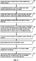
- FIG. 4 is a flowchart illustrating an example operation of the system of this disclosure. The blocks of FIG. 4 will be described in terms of FIG. 1 , unless otherwise noted.
- inverter circuitry 108 may receive electrical energy from DC power source 112 (500).
- DC power source 112 may be implemented as a battery, including a rechargeable battery.
- Inverter circuitry 108 is configured to convert the received electrical energy from DC power source 112 into AC power 116 (502). In some examples AC power 116 is three-phase electrical power. Inverter circuitry 108 may further output AC power 116 to electrical machine 106 (504). As described above in relation to FIG. 2 , switching circuits of inverter circuitry 108 may superimpose noise, which may include one or more disturbances that may distort characteristics of AC power 116.
- Sensors 118 may sense, e.g. measure, one or more characteristics of electrical machine 106 (506). Each sensor of sensors 118 may output a feedback signal (508). Because the noise from inverter circuitry 108 may couple to either the sensors, or the conductors carrying signals or power to and from sensors 118, the feedback signal may include both an indication of the one or more characteristics of the electrical machine, and the noise. In other words, the feedback signal may include a feedback information component and a noise component because the sensor receives the noise component, including one or more noise frequencies, from electrical machine 106.
- Each of feedback signal filters 102A - 102X may receive a respective feedback signal from a respective sensor, e.g. a temperature sensor or speed sensor (510). As described above in relation to FIGS. 2 and 3 , the respective filter circuit of feedback signal filters 102A - 102X may remove, or attenuate, the noise from the feedback signal (512). As described above in relation to FIG. 3 , various filter configurations may be implemented in a respective feedback signal filter based on the expected information component and the noise component in the feedback signal.
- Inverter circuitry 108 e.g. processing circuitry 110 connected to or part of inverter circuitry 108, may receive a respective feedback signal from feedback signal filters 102A - 102X (514). Based on the indication of the one or more characteristics of the electrical machine in the information component of the feedback signal, processing circuitry 110 may adjust one or more settings of inverter circuitry 108 to adjust AC power 116 output to electrical machine 106 (516). Processing circuitry 110 may adjust any one or more of output voltage amplitude, frequency, or other characteristics of AC power 116.
- the functions described above may be implemented in hardware, software, firmware, or any combination thereof.
- the various components of FIG. 1 such as processing circuitry 110 and feedback signal filters 102A - 102X may be implemented in hardware, software, firmware, or any combination thereof.
- the functions may be stored on or transmitted over, as one or more instructions or code, a computer-readable medium and executed by a hardware-based processing unit.
- Computer-readable media may include computer-readable storage media, which corresponds to a tangible medium such as data storage media, or communication media including any medium that facilitates transfer of a computer program from one place to another, e.g., according to a communication protocol.
- computer-readable media generally may correspond to (1) tangible computer-readable storage media which is non-transitory or (2) a communication medium such as a signal or carrier wave.
- Data storage media may be any available media that can be accessed by one or more computers or one or more processors to retrieve instructions, code and/or data structures for implementation of the techniques described in this disclosure.
- a computer program product may include a computer-readable medium.
- non-transitory may indicate that the storage medium is not embodied in a carrier wave or a propagated signal.
- a non-transitory storage medium may store data that can, over time, change (e.g., in RAM or cache).
- such computer-readable storage media may include random access memory (RAM), read only memory (ROM), programmable read only memory (PROM), erasable programmable read only memory (EPROM), electronically erasable programmable read only memory (EEPROM), flash memory, a hard disk, a compact disc ROM (CD-ROM), a floppy disk, a cassette, magnetic media, optical media, or other computer readable media.
- RAM random access memory
- ROM read only memory
- PROM programmable read only memory
- EPROM erasable programmable read only memory
- EEPROM electronically erasable programmable read only memory
- flash memory a hard disk, a compact disc ROM (CD-ROM), a floppy disk, a cassette, magnetic media, optical media, or other computer readable media.
- CD-ROM compact disc ROM
- floppy disk a cassette
- magnetic media magnetic media
- optical media or other computer readable media.
- an article of manufacture may include computer-readable storage media.
- any connection is properly termed a computer-readable medium.
- a computer-readable medium For example, if instructions are transmitted from a website, server, or other remote source using a coaxial cable, fiber optic cable, twisted pair, digital subscriber line (DSL), or wireless technologies such as infrared, radio, and microwave, then the coaxial cable, fiber optic cable, twisted pair, DSL, or wireless technologies such as infrared, radio, and microwave are included in the definition of medium.
- DSL digital subscriber line
- computer-readable storage media and data storage media do not include connections, carrier waves, signals, or other transient media, but are instead directed to non-transient, tangible storage media. Combinations of the above should also be included within the scope of computer-readable media.
- processors such as one or more DSPs, general purpose microprocessors, ASICs, FPGAs, or other equivalent integrated or discrete logic circuitry. Accordingly, the term "processor,” and “processing circuitry” as used herein, may refer to any of the foregoing structure or any other structure suitable for implementation of the techniques described herein. Also, the techniques could be fully implemented in one or more circuits or logic elements.
- the techniques of this disclosure may be implemented in a wide variety of devices or apparatuses, including, an integrated circuit (IC) or a set of ICs (e.g., a chip set).
- IC integrated circuit
- a set of ICs e.g., a chip set.
- Various components, modules, or units are described in this disclosure to emphasize functional aspects of devices configured to perform the disclosed techniques, but do not necessarily require realization by different hardware units. Rather, as described above, various units may be combined in a hardware unit or provided by a collection of interoperative hardware units, including one or more processors as described above, in conjunction with suitable software and/or firmware.
Abstract
Description
- The disclosure relates to filtering signals for electromagnetic compatibility.
- Electric and hybrid vehicles, and similarly electrically powered equipment may include a direct current (DC) power source such as a battery, that drives one or more electrical machines. For example, the drive train of the electric or hybrid-electric vehicle may control an electrical machine that receives three-phase power from an inverter configured to convert the power from the DC power source into alternating current (AC) power. Processing circuitry may receive feedback signals from the electrical machine in the drive train and adjust the output of the inverter based on the received feedback signals.
- In general, the disclosure describes techniques to filter unwanted noise from feedback signals of an electrical machine, such as an electrical machine in the drive train of an electric vehicle. In the example of an electrical machine that receives AC power from an inverter, the switching circuitry in the inverter may superimpose noise on the power signals received by the electrical machine. The noise may couple to one or more sensors inside the electrical machine and cause noise in the output signals from the one or more sensors. The sensor output signals, which may include temperature, speed and position of the electrical machine, may act as feedback signals for a closed loop control system for the electrical machine. The noise in the feedback signals may impact the closed loop operation of the electrical machine. Also, the noise in the feedback signals may cause electromagnetic compatibility (EMC) issues, either by direct radiated emissions or by coupling to other circuits in the vehicle wiring harness as the feedback signals travel from the electrical machine to processing circuitry that may operate the closed loop control system. The techniques of this disclosure may include filter circuitry located inside or very close to the electrical machine that filters out the unwanted noise in the feedback signals.
- In one example, the disclosure is directed to a method comprising: receiving, by an inverter circuitry, electrical energy from a direct-current (DC) power source, converting, by the inverter circuitry, the received electrical energy into three-phase alternating-current (AC) power, outputting, by the inverter circuitry, the three-phase power to an electrical machine, wherein the output three-phase power comprises a noise, sensing, by a sensor, one or more characteristics of the electrical machine, outputting, by the sensor, a feedback signal. The feedback signal comprises: an indication of the one or more characteristics of the electrical machine, and the noise, wherein the sensor receives the noise from the electrical machine. The method may further include receiving, by a filter circuit, the feedback signal from the sensor, removing, by the filter circuit, the noise from the feedback signal, receiving, by the inverter circuitry, the feedback signal from the filter circuit, and adjusting, by the inverter circuitry, the three-phase power output to the electrical machine based on the indication of the one or more characteristics of the electrical machine.
- In another example, a system comprising: an electrical machine configured to drive a mechanical load, an inverter circuitry configured to provide power to the electrical machine, a sensor configured to measure a characteristic of the electrical machine and output a first signal indicating the measured characteristic. The system may also include a filter circuit configured to receive the first signal from the sensor, remove noise from the first signal, output a second signal indicating the measured characteristic.
- In another example, the disclosure is directed to an apparatus comprising: a filter circuit configured to: receive a feedback signal from a sensor. The feedback signal comprises a feedback information component and a noise component. The apparatus is further configured to remove the noise component from the feedback signal and output the feedback signal comprising the information component. The apparatus also may include inverter circuitry configured to: receive DC power and output AC power receive the feedback signal from the filter circuit and adjust the output AC power based on the received information component of the feedback signal.
- The details of one or more examples of the disclosure are set forth in the accompanying drawings and the description below. Other features, objects, and advantages of the disclosure will be apparent from the description and drawings, and from the claims.
-
-
FIG. 1 is a block diagram illustrating an electrical machine driven by an inverter that include feedback filtering according to one or more techniques of this disclosure. -
FIG. 2 is a schematic diagram illustrating an example feedback filter circuit according to one or more techniques of this disclosure. -
FIG. 3 is a schematic diagram illustrating a second example of a feedback filter circuit according to one or more techniques of this disclosure. -
FIG. 4 is a flowchart illustrating an example operation of the system of this disclosure. - This disclosure describes techniques to filter unwanted noise from feedback signals of an electrical machine, such as an electrical machine in the drive train of an electric vehicle, to improve electrical performance and elevate electromagnetic compatibility. For an electrical machine that receives AC power from an inverter, the switching circuitry in the inverter may cause noise on the power signals received by the electrical machine. The noise may couple to one or more sensors inside the electrical machine and cause noise in the output signals from the one or more sensors. The sensor output signals may include temperature, speed and position of the electrical machine and may act as feedback signals for a closed loop control system for the electrical machine. The noise in the feedback signals may impact the closed loop operation of the electrical machine that can affect the performance of output AC power to electrical machine. Also, the noise in the feedback signals may couple to other circuits in a wiring harness as the feedback signals travel from the electrical machine to disturb electrically or electromagnetically processing circuitry of other units that may operate the closed loop control system. In some examples, the noise may cause issues with other components of the equipment powered by the electrical machine. In some examples, the noise may also radiate and cause electromagnetic compatibility (EMC) issues with sensitive equipment. In this disclosure, the term "noise" means any type of electrical or electromagnetic noise, unless otherwise noted.
- The techniques of this disclosure may include filter circuitry located inside or very close, e.g. mounted on or adjacent to the electrical machine that filters out the unwanted noise in the feedback signals. Locating the filtering circuitry close to the electrical machine may prevent noise from coupling to the wiring harness. Also, filtering the feedback signals may result in compact, lightweight, and inexpensive filtering circuitry when compared to other electromagnetic compatibility (EMC) management techniques.
-
FIG. 1 is a block diagram illustrating an electrical machine driven by an inverter that include feedback filtering according to one or more techniques of this disclosure. The example ofsystem 100 may drive a variety ofloads 111, which may include the drive train of an electric or hybrid-electric vehicle, a pumping station, a hoist, crane or other similar loads. In some examples,DC power source 112 may be charged by a solar photovoltaic (PV) system or some other charging system (not shown inFIG. 1 ). Examples of a vehicle may include cars, trucks, buses, motorcycles, recreational vehicles (RVs), tractors, all-terrain vehicles, watercraft, or any other type of vehicle. - In the example of
FIG. 1 ,system 100 includeselectrical machine 106 configured to driveload 111, inverter circuitry 108 (shown as inverter 108),DC power source 112, andfeedback signal filters 102A - 102X. In some examples,inverter circuitry 108 may also includeprocessing circuitry 110. In other examples,processing circuitry 110 may be separate frominverter circuitry 108 but operatively coupled toinverter circuitry 108. -
Electrical machine 106 may be any type of electrical motor configured to operate withAC power 116, such as synchronous and asynchronous machines. In some examples,power 116 frominverter circuitry 108 may be single phase, three-phase or any other type of AC power.Electrical machine 106 may be configured and sized to drive large orsmall loads 111 at a variety of speeds and torque output.Electrical machine 106 may also be configured to stop and start from any position of angular rotation. For example,shaft 120 may rotate with respect to a reference angular position, e.g. a reference angle of zero degrees or zero radians.Electrical machine 106 may be configured to start at a first angular deviation from the reference angle and stop at a second angular deviation from the reference position. -
Electrical machine 106 may include electrical and mechanical components surrounded by and protected by ahousing 122. In some examples, electrical machine may includeshaft 120, bearings to supportshaft 120, electrical windings or coils, and other related components. -
Electrical machine 106 may also include one ormore sensors 118 configured to sense one or more characteristics ofelectrical machine 106. Some examples of sensors may include a resolver configured to measure a speed and a position of an electrical machine, a temperature sensor, a current sensor configured to measure a magnitude of current, an impedance sensor, a Hall effect sensor, a speed sensor, a voltage sensor, a volt-ampere reactive (vars) sensor, and a radiated emission sensor. In some examples the current sensor and vars sensor may be configured to measure the magnitude of power used by one or more phases ofelectrical machine 106. In some examples one or more ofsensors 118 may be mounted within thehousing 122 ofelectrical machine 106. In other examples, one or more ofsensors 118 may be mounted on the exterior of thehousing 122 ofelectrical machine 106. For example, a first temperature sensor ofsensors 118 may be configured to measure shaft temperature, windings temperature or other temperatures withinelectrical machine 106, while a second temperature sensor may be configured to measure external temperature of the environment aroundelectrical machine 106. In some examples, the resolver may be configured to output sine and/or cosine information, which may provide angular position and speed. -
Loads 111 may be any type of load, as noted above, such as a vehicle drivetrain. In some examples, load 111 may be configured to convert angular rotation into lateral movement. -
Inverter circuitry 108 is configured to receive DC power andoutput AC power 116.Inverter circuitry 108 may include switching circuits that convert the received DC power into AC power, such that the AC power signal approximates a sine wave shaped signal. The switching circuits may also generate a noise component that may be superimposed on the AC power signal. The noise component may include any number of frequencies and harmonics of frequencies. In some examples, the noise component is carried along with the AC power signal toelectrical machine 106. - In some examples,
inverter circuitry 108 may be operatively connected to processingcircuitry 110. In the example of a vehicle,processing circuitry 110 may receive data, commands and other information from other processors and systems within the vehicle.Processing circuitry 110 may also receive feedback signals from the one ormore sensors 118 which may indicate measured characteristics ofelectrical machine 106. In some examples,processing circuitry 110 may adjust the operation ofinverter circuitry 108 based on the measured characteristic. In other words, processingcircuitry 110 may operate as part of a closed loop control system forelectrical machine 106 and adjust theoutput AC power 116 based on a received information component of the feedback signal. For example, a temperature sensor ofsensors 118 may indicate thatelectrical machine 106 has exceeded a temperature threshold.Processing circuitry 110 may reduce the amplitude, frequency or some other characteristic ofAC power 116 to help reduce the operating temperature ofelectrical machine 106. - Examples of
processing circuitry 110 may include any one or more of a microcontroller (MCU), e.g. a computer on a single integrated circuit containing a processor core, memory, and programmable input/output peripherals, a microprocessor (µP), e.g. a central processing unit (CPU) on a single integrated circuit (IC), a controller, a digital signal processor (DSP), an application specific integrated circuit (ASIC), a field-programmable gate array (FPGA), a system on chip (SoC) or equivalent discrete or integrated logic circuitry. A processor may be integrated circuitry, i.e., integrated processing circuitry, and that the integrated processing circuitry may be realized as fixed hardware processing circuitry, programmable processing circuitry and/or a combination of both fixed and programmable processing circuitry. Accordingly, the terms "processing circuitry," "processor" or "controller," as used herein, may refer to any one or more of the foregoing structures or any other structure operable to perform techniques described herein. - In some examples,
processing circuitry 110 may include computer-readable storage media, such as a microcontroller. In other examples,processing circuitry 110 may be operatively coupled to separate computer-readable storage media. In this disclosure computer-readable storage media may include random access memory (RAM), read only memory (ROM), programmable read only memory (PROM), erasable programmable read only memory (EPROM), electronically erasable programmable read only memory (EEPROM), flash memory, and similar devices. In some examples the computer readable storage media may store instructions that cause the processing circuitry to execute the functions described herein. In some examples, the computer readable storage media may store data, such as configuration information, temporary values and other types of data used to perform the functions of this disclosure. - In some examples the noise generated by switching circuits of
inverter circuitry 108 may couple to one or more ofsensors 118. In some examples, noise within motor coils of one or more phases ofelectrical machine 106 may couple tosensors 118. The feedback signal fromsensors 118 may include both a feedback information component and a noise component. In other words, the feedback signal may include both an indication of the one or more characteristics of the electrical machine (e.g. temperature or speed), and a noise frequency superimposed on the feedback signal. The sensor may receive the noise frequency fromelectrical machine 106. As described above, the noise component may include many different noise frequencies, including harmonics of noise frequencies. - Should
inverter circuitry 108 receive feedback signals with both the feedback information component along with the noise component, the combined feedback signal may negatively impact the closed loop operation ofinverter circuitry 108. In some examples, the noise component comprising one or more noise frequencies may causeprocessing circuitry 110 to apply control signals toinverter circuitry 108 based on the noise component. In some examples, the noise component may causeprocessing circuitry 110 to inaccurately process the information component of the feedback signals,e.g. processing circuitry 110 may determine that the feedback signal indicates a speed that is higher or lower than the actual speed ofelectrical machine 106. In some examples, the noise component in the feedback signal may also be further superimposed onAC power 116 output byinverter circuitry 108. - Feedback signal filters 102A - 102X are configured to receive the feedback signal from the sensor and remove noise, such as the noise frequency or frequencies, from the feedback signal. In other words, feedback signal filters 102A - 102X include a filter circuit that will receive a first signal from a sensor of
sensors 118 remove at least some of the noise from the first signal and output a second signal indicating the measured characteristic. The output second signal sent toinverter circuitry 108 will include the measured characteristic, e.g. current magnitude or angular position, but will remove, or at least reduce the magnitude, of the noise component coupled to the sensor fromelectrical machine 106. In some examples, feedback signal filters 102A - 102X may be implemented using analog components. In other examples, feedback signal filters 102A - 102X may be implemented as digital filters or some combination of both analog and digital filtering. - Feedback signal filters adjacent to
electrical machine 106, but outside ofhousing 122, e.g. feedback signal filters 102N - 102X connect toelectrical machine 106 viaEMC braid 104. EMC braid 104 may be implemented as any type of electrical conductor with a low impedance current path. In someexamples EMC braid 104 may be implemented as a braided wire conductor. In other examples, EMC braid 104 may be implemented as a relatively large diameter wire. EMC braid 104 may conduct the filtered noise component from feedback signal filters 102N - 102X on the exterior ofhousing 122 back toelectrical machine 106. -
Electrical machine 106,inverter circuitry 108,DC power source 112 and other components ofsystem 100 may connect to reference 114.Reference 114 may act as the system ground forsystem 100. In some examples, such as for a vehicle,reference 114 may be the chassis ground for the vehicle. In the example of a building or similar structure,reference 114 may also connect to protective earth ground. Feedback signal filters 102A - 102M located withinhousing 122 may connect to the same reference aselectrical machine 106. - Feedback signal filters 102A - 102X may be of any number of feedback signal filters of
system 100. In some examples, each sensor ofsensors 118 may connect to a separate feedback signal filter. In other examples, two or more feedback signals from two or more sensors may connect to a single feedback signal filter of feedback signal filters 102A - 102X. - Feedback signal filters 102A - 102X may be located inside, near or mounted on
electrical machine 106. In the example ofsystem 100, feedback signal filters 102A - 102M are located inside thehousing 122 ofelectrical machine 106. Feedback signal filters 102N - 102X may be located near, e.g. adjacent to or mounted onhousing 122 ofelectrical machine 106. The signal path fromsensors 118 ofelectrical machine 106 may travel several centimeters to a meter or more before reachinginverter circuitry 108. In the example ofsystem 100, feedback signal filters 102A - 102X may be mounted inside, close to or adjacent toelectrical machine 106 such that the signal path betweenelectrical machine 106 and the feedback signal filters is much shorter than the signal path between the feedback signal filters andinverter circuitry 108. The location of feedback signal filters 102A - 102X insystem 100 may provide an advantage over other locations because the feedback signal filters may reduce or remove the noise component before the feedback signal travels down the remainder of the signal path toinverter circuitry 108. The remainder of the signal path may run near, or in the same wire harness as other signals in the overall system, e.g. a vehicle, hoist, and so on. By filtering the noise before the feedback signal travels along the remainder of the signal path, feedback signal filters 102A - 102X may prevent the noise from coupling to other conductors in the wire harness. Also, in some examples, the remainder of the signal path may be long enough to act as an antenna. Noisy signals in the remainder of the signal path may cause noise to radiate into the environment. Coupled or radiated noise may affect other circuits outside the electrical machine. Said another way, noise in the feedback signals may cause electromagnetic compatibility (EMC) issues, either by direct radiated emissions or by coupling to other circuits in the vehicle wiring harness as the feedback signals travel from the electrical machine to processing circuitry. In other words, the filter circuits of feedback signal filters 102A - 102X may be located adjacent to the electrical machine such that the filter circuit is configured to prevent noise from the feedback signals from coupling to circuits outside the electrical machine. - The arrangement of
system 100 may provide advantages over other examples of systems that include inverters. Rather than filtering the noise at the output ofinverter circuitry 108, the techniques of this disclosure filter the output signals of the sensors by using filter circuits located close to, e.g. adjacent to,electrical machine 106. In this manner, the filter circuits of this disclosure may use smaller, less expensive and lighter components for the relatively low power sensor output signals. In contrast, filtering the high-power signals ofAC power 116 may require components with high current ratings, which may increase the cost, weight and size of the filter components. In addition, filtering noise fromAC power 116 may also dissipate at least some ofAC power 116 as heat and therefore provide less efficient use of the energy fromDC power source 112 toelectrical machine 106. In the example of an electric vehicle, the techniques of this disclosure may increase the range, because of the improved efficiency and lighter weight, when compared to other techniques. By locating feedback signal filters 102A - 102X nearelectrical machine 106, e.g. in contrast to including filter circuits atinverter circuitry 108, the techniques of this disclosure may prevent noise from coupling to the vehicle wiring harness or radiating to impact other circuits outside ofelectrical machine 106. In some examples, including feedback signal filters 102A - 102X in the feedback loop may reduce the amount of noise coupled ontoAC power 116. -
FIG. 2 is a schematic diagram illustrating an example feedback filter circuit according to one or more techniques of this disclosure.Circuit 200 is one possible implementation of a filter circuit for feedback signal filters 102A - 102X described above in relation toFIG. 1 . - In the example of
FIG. 2 , anoisy input signal 202 from a sensor ofsensors 118 described above in relation toFIG. 1 , connects to inputterminals Input terminals common mode choke 206. In some examples,input terminal 220 may be considered a "line terminal" andinput terminal 222 may be considered a "neutral terminal."Output terminal 228 ofcommon mode choke 206 is therefore a line terminal andoutput terminal 226 is the neutral terminal in the example ofcircuit 200.Circuit 200 outputs filteredoutput signal 204 fromoutput terminals - Capacitor C1 210 in series with
capacitor C2 212 connectsoutput terminal 228 tooutput terminal 226.EMC ground 214 connects to the node between capacitor C1210 andcapacitor C2 212.EMC ground 214 may electrically connect to EMC braid 104 described above in relation toFIG. 1 . -
Common mode choke 206 includes line and neutral windings that are wound on a single core. The "line" winding connects terminal 220 toterminal 228 and the neutral winding connects terminal 222 to terminal 226 in the example ofcircuit 200. Thereforeterminals terminals terminals common mode choke 206 is an electrical filter that blocks high frequency noise common to the line and neutral windings while allowing the desired signal with the information component to pass. - Noise coupled to a sensor of
sensors 118 may be coupled on both output lines of the sensor, and therefore be coupled as common mode noise. In common mode, the current in the line and neutral windings travel in the same direction, so the combined magnetic flux adds to create an opposing field to block the common mode noise. Characteristics of a common mode choke include the impedance at a selected frequency band, the electrical current rating and so on. In the example ofcircuit 200, selecting the characteristics ofcommon mode choke 206 may determine the frequencies of common mode noise coupled to the feedback signal to be attenuated or removed. - The series combination of capacitors C1 210 and
C2 212 is in parallel withcommon mode choke 206. Capacitors C1 210 andC2 212 may conduct additional AC signals toEMC ground 214. For example,capacitor C2 212 may conduct an AC signal, e.g. voltage ripple, atneutral output terminal 226 toEMC ground 214. -
FIG. 3 is a schematic diagram illustrating a second example of a feedback filter circuit according to one or more techniques of this disclosure. As withcircuit 200,circuit 300 is one possible example of a filter circuit for feedback signal filters 102A - 102X described above in relation toFIG. 1 . The example ofcircuit 300 provides for a variety of optional configurations to implement a filter circuit based on the type of unwanted noise to be filtered from the feedback signal. -
Noisy input signal 302 enterscircuit 300 viainput terminal 320 andinput terminal 322. In the example ofFIG. 3 ,input terminal 320 andoutput terminal 328 may be considered the line terminals andinput terminal 322 andoutput terminal 326 may be considered the neutral terminals. Filteredoutput signal 304 leavescircuit 300 viaoutput terminals -
Common mode choke 306 andcapacitors C1 310 andC2 312 are examples ofcommon mode choke 206 and capacitors C1210 andC2 212 and have the same functions and characteristics described above in relation tocircuit 200. In addition,resistor R1 330 connects the line terminals ofcommon mode choke 306, whileresistor R2 332 connects the neutral terminals ofcommon mode choke 306. In some examples,resistor R1 330 and/orresistor R2 332 may be high resistance or omitted as an open circuit when usingcommon mode choke 306 incircuit 300. In other examples,resistor R1 330 and/orresistor R2 332 may have a very low resistance or act as a short circuit to bypass and removecommon mode choke 306 fromcircuit 300. In this manner resistorsR1 330 andR2 332 provide for a variety of optional configurations to implement the filter circuit ofcircuit 300. - Similarly,
resistor R3 333 andR4 334 may be omitted as an open circuit when usingferrite bead L 334 andferrite bead N 336.Resistor R3 333 andR4 334 may be a low resistance or short circuit to bypass and removeferrite bead L 334 andferrite bead N 336 fromcircuit 300. -
Ferrite bead L 334 connectsinput terminal 320 to the input line terminal ofcommon mode choke 306.Ferrite bead N 336 connectsinput terminal 322 to the input neutral terminal ofcommon mode choke 306.Ferrite bead L 334 andferrite bead N 336 act as a single choke to reduce or eliminate differential mode noise, e.g. blocking the high-frequency AC noise while letting the DC or lower frequency AC signal pass. As with a common mode choke, selecting the size and other characteristics offerrite bead L 334 andferrite bead N 336 may determine the frequencies to be attenuated. -
Capacitor C6 344 connects the line terminal and neutral terminal ofcommon mode choke 306.Capacitor C6 344 may couple differential AC signals between the line and neutral paths ofcircuit 300. - Similar to
capacitors C1 310 andC2 312,capacitor C3 346 connects in series withcapacitor C4 334 to connect the line terminal and neutral terminal ofcommon mode choke 306 in parallel withcapacitor C6 344. The node betweencapacitor C3 346 andcapacitor C4 334 connects toGND 340.GND 340 andGND 342 may connect toelectrical machine 106 viaEMC braid 104 as described above in relation toFIG. 1 . -
Capacitor C5 320 connectsline output terminal 328 andneutral output terminal 326. Similar tocapacitor C6 344,capacitor C5 320 may couple differential AC signals between the line andneutral output terminals circuit 300. Selecting various combinations of components, as well as component characteristics, e.g. capacitance, resistance value and so on, determines the filter characteristics ofcircuit 300. -
FIG. 4 is a flowchart illustrating an example operation of the system of this disclosure. The blocks ofFIG. 4 will be described in terms ofFIG. 1 , unless otherwise noted. - As described above in relation to
FIG. 1 ,inverter circuitry 108 may receive electrical energy from DC power source 112 (500). In some examples,DC power source 112 may be implemented as a battery, including a rechargeable battery. -
Inverter circuitry 108 is configured to convert the received electrical energy fromDC power source 112 into AC power 116 (502). In someexamples AC power 116 is three-phase electrical power.Inverter circuitry 108 may furtheroutput AC power 116 to electrical machine 106 (504). As described above in relation toFIG. 2 , switching circuits ofinverter circuitry 108 may superimpose noise, which may include one or more disturbances that may distort characteristics ofAC power 116. -
Sensors 118 may sense, e.g. measure, one or more characteristics of electrical machine 106 (506). Each sensor ofsensors 118 may output a feedback signal (508). Because the noise frominverter circuitry 108 may couple to either the sensors, or the conductors carrying signals or power to and fromsensors 118, the feedback signal may include both an indication of the one or more characteristics of the electrical machine, and the noise. In other words, the feedback signal may include a feedback information component and a noise component because the sensor receives the noise component, including one or more noise frequencies, fromelectrical machine 106. - Each of feedback signal filters 102A - 102X may receive a respective feedback signal from a respective sensor, e.g. a temperature sensor or speed sensor (510). As described above in relation to
FIGS. 2 and3 , the respective filter circuit of feedback signal filters 102A - 102X may remove, or attenuate, the noise from the feedback signal (512). As described above in relation toFIG. 3 , various filter configurations may be implemented in a respective feedback signal filter based on the expected information component and the noise component in the feedback signal. -
Inverter circuitry 108,e.g. processing circuitry 110 connected to or part ofinverter circuitry 108, may receive a respective feedback signal from feedback signal filters 102A - 102X (514). Based on the indication of the one or more characteristics of the electrical machine in the information component of the feedback signal,processing circuitry 110 may adjust one or more settings ofinverter circuitry 108 to adjustAC power 116 output to electrical machine 106 (516).Processing circuitry 110 may adjust any one or more of output voltage amplitude, frequency, or other characteristics ofAC power 116. - In one or more examples, the functions described above may be implemented in hardware, software, firmware, or any combination thereof. For example, the various components of
FIG. 1 , such asprocessing circuitry 110 and feedback signal filters 102A - 102X may be implemented in hardware, software, firmware, or any combination thereof. If implemented in software, the functions may be stored on or transmitted over, as one or more instructions or code, a computer-readable medium and executed by a hardware-based processing unit. Computer-readable media may include computer-readable storage media, which corresponds to a tangible medium such as data storage media, or communication media including any medium that facilitates transfer of a computer program from one place to another, e.g., according to a communication protocol. In this manner, computer-readable media generally may correspond to (1) tangible computer-readable storage media which is non-transitory or (2) a communication medium such as a signal or carrier wave. Data storage media may be any available media that can be accessed by one or more computers or one or more processors to retrieve instructions, code and/or data structures for implementation of the techniques described in this disclosure. A computer program product may include a computer-readable medium. - The term "non-transitory" may indicate that the storage medium is not embodied in a carrier wave or a propagated signal. In certain examples, a non-transitory storage medium may store data that can, over time, change (e.g., in RAM or cache).
- By way of example, and not limitation, such computer-readable storage media, may include random access memory (RAM), read only memory (ROM), programmable read only memory (PROM), erasable programmable read only memory (EPROM), electronically erasable programmable read only memory (EEPROM), flash memory, a hard disk, a compact disc ROM (CD-ROM), a floppy disk, a cassette, magnetic media, optical media, or other computer readable media. In some examples, an article of manufacture may include computer-readable storage media.
- Also, any connection is properly termed a computer-readable medium. For example, if instructions are transmitted from a website, server, or other remote source using a coaxial cable, fiber optic cable, twisted pair, digital subscriber line (DSL), or wireless technologies such as infrared, radio, and microwave, then the coaxial cable, fiber optic cable, twisted pair, DSL, or wireless technologies such as infrared, radio, and microwave are included in the definition of medium. It should be understood, however, that computer-readable storage media and data storage media do not include connections, carrier waves, signals, or other transient media, but are instead directed to non-transient, tangible storage media. Combinations of the above should also be included within the scope of computer-readable media.
- Instructions may be executed by one or more processors, such as one or more DSPs, general purpose microprocessors, ASICs, FPGAs, or other equivalent integrated or discrete logic circuitry. Accordingly, the term "processor," and "processing circuitry" as used herein, may refer to any of the foregoing structure or any other structure suitable for implementation of the techniques described herein. Also, the techniques could be fully implemented in one or more circuits or logic elements.
- The techniques of this disclosure may be implemented in a wide variety of devices or apparatuses, including, an integrated circuit (IC) or a set of ICs (e.g., a chip set). Various components, modules, or units are described in this disclosure to emphasize functional aspects of devices configured to perform the disclosed techniques, but do not necessarily require realization by different hardware units. Rather, as described above, various units may be combined in a hardware unit or provided by a collection of interoperative hardware units, including one or more processors as described above, in conjunction with suitable software and/or firmware.
- Various examples of the disclosure have been described. These and other examples are within the scope of the following claims.
Claims (14)
- A system comprising:an electrical machine configured to drive a mechanical load;an inverter circuitry configured to provide power to the electrical machine;a sensor configured to measure a characteristic of the electrical machine and output a first signal indicating the measured characteristic; anda filter circuit configured to:receive the first signal from the sensor;remove noise from the first signal;output a second signal indicating the measured characteristic.
- The system of claim 1, further comprising processing circuitry configured to:receive the second signal;adjust operation of the inverter circuitry based on the measured characteristic.
- The system of any combination of claims 1 and 2, wherein the filter circuit is located adjacent or inside the electrical machine such that the filter circuit is configured to prevent noise from the first signal from coupling to one or more circuits outside the electrical machine.
- The system of any combination of claims 1-3, wherein the sensor comprises a resolver configured to measure a speed and a position of the electrical machine.
- The system of claim 4, wherein the position of the electrical machine comprises an angular deviation from a reference angle.
- The system of any combination of claims 1-5, wherein the sensor comprises a temperature sensor configured to measure an operating temperature of the electrical machine.
- The system of any combination of claims 1-6, wherein the filter comprises a common mode choke circuit.
- The system of any combination of claims 1-7, wherein the filter comprises a first capacitor in series with a second capacitor, and the first capacitor and second capacitor are in parallel with the common mode choke circuit.
- A method comprissing:receiving, by an inverter circuitry, electrical energy from a direct-current (DC) power source;converting, by the inverter circuitry, the received electrical energy into three-phase alternating-current (AC) power;outputting, by the inverter circuitry, the three-phase power to an electrical machine, wherein the output three-phase power comprises a noise;sensing, by a sensor, one or more characteristics of the electrical machine;outputting, by the sensor, a feedback signal, wherein the feedback signal comprises:an indication of the one or more characteristics of the electrical machine, andthe noise, wherein the sensor receives the noise from the electrical machine;receiving, by a filter circuit, the feedback signal from the sensor;removing, by the filter circuit, the noise from the feedback signal;receiving, by the inverter circuitry, the feedback signal from the filter circuit; andadjusting, by the inverter circuitry, the output of the three-phase power to the electrical machine based on the indication of the one or more characteristics of the electrical machine.
- An apparatus comprising:an electrical machine configured to receive alternating current (AC) power and drive a mechanical load;a filter circuit configured to:receive a feedback signal from a sensor, wherein the feedback signal comprises a feedback information component and a noise component;remove the noise component from the feedback signal; andoutput the feedback signal comprising the feedback information component, wherein the filter circuit is located within a housing of the electrical machine and wherein the feedback information component includes one or more characteristics of the electrical machine.
- The apparatus of claim 10, wherein the sensor is a first sensor and the filter circuit is a first filter circuit, the apparatus further comprising a second filter circuit located on the exterior of the housing, the second filter circuit is configured to:receive a second feedback signal from a second sensor, wherein the second feedback signal comprises a second feedback information component and the noise component;remove the noise component from the second feedback signal; andoutput the second feedback signal comprising the second feedback information component.
- The apparatus of claim 10 or 11, wherein the sensor comprises at least one of a resolver configured to measure a speed and a position of an electrical machine, a temperature sensor, a current sensor configured to measure a magnitude of current, an impedance sensor, a volt-ampere reactive (vars) sensor, and a radiated emission sensor.
- The apparatus of any combination of claims 10 - 12, wherein the filter comprises a common mode choke circuit.
- The apparatus of any combination of claims 10 - 13, wherein the filter comprises a first capacitor in series with a second capacitor, and the first capacitor and second capacitor are in parallel with the common mode choke circuit.
Applications Claiming Priority (1)
| Application Number | Priority Date | Filing Date | Title |
|---|---|---|---|
| US202063039819P | 2020-06-16 | 2020-06-16 |
Publications (1)
| Publication Number | Publication Date |
|---|---|
| EP3926813A1 true EP3926813A1 (en) | 2021-12-22 |
Family
ID=76483140
Family Applications (1)
| Application Number | Title | Priority Date | Filing Date |
|---|---|---|---|
| EP21179588.5A Pending EP3926813A1 (en) | 2020-06-16 | 2021-06-15 | Electromagnetic emission rejection filter in hybrid/electric vehicles |
Country Status (3)
| Country | Link |
|---|---|
| US (1) | US11552556B2 (en) |
| EP (1) | EP3926813A1 (en) |
| CN (1) | CN113824268A (en) |
Families Citing this family (1)
| Publication number | Priority date | Publication date | Assignee | Title |
|---|---|---|---|---|
| CN114257079A (en) * | 2021-12-23 | 2022-03-29 | 无锡睿勤科技有限公司 | Power utilization equipment and power supply system |
Citations (4)
| Publication number | Priority date | Publication date | Assignee | Title |
|---|---|---|---|---|
| US20020117318A1 (en) * | 2000-05-17 | 2002-08-29 | Nec Corporation | Method and apparatus for reducing radiant noise energy |
| CN203734632U (en) * | 2013-12-10 | 2014-07-23 | 国家电网公司 | Electromagnetic interference filter suitable for high voltage Hall voltage sensor |
| CN209805612U (en) * | 2019-05-21 | 2019-12-17 | 上海大郡动力控制技术有限公司 | Mounting structure of motor rotary transformer and temperature signal line EMI filter |
| US20200067478A1 (en) * | 2018-08-27 | 2020-02-27 | Mando Corporation | Inductor device, filter device, and steering system |
Family Cites Families (7)
| Publication number | Priority date | Publication date | Assignee | Title |
|---|---|---|---|---|
| US20030048157A1 (en) * | 2001-09-10 | 2003-03-13 | Ricks Lamar Floyd | Molded common mode ferrite filter for electronic sensors |
| JP2006020389A (en) * | 2004-06-30 | 2006-01-19 | Yaskawa Electric Corp | Noise filter and motor drive mounted with it |
| CN102185547B (en) * | 2011-03-30 | 2012-12-19 | 浙江大学 | Method for controlling non-radial displacement transducer of multi-phase and single-winding bearingless motor |
| WO2019010518A1 (en) * | 2017-07-11 | 2019-01-17 | LAU, Siu Hei | Three phase permanent magnet motor driving method |
| DE102017213543B4 (en) * | 2017-08-04 | 2019-08-08 | Conti Temic Microelectronic Gmbh | Filter arrangement, voltage converter with a filter arrangement |
| CN208190535U (en) * | 2018-01-26 | 2018-12-04 | 深圳和而泰智能控制股份有限公司 | A kind of electric machine control system and electrical equipment |
| CN112671295B (en) * | 2020-11-30 | 2022-05-27 | 西北工业大学 | Rotor initial position detection method and system based on motor common-mode current |
-
2021
- 2021-06-08 US US17/342,386 patent/US11552556B2/en active Active
- 2021-06-15 EP EP21179588.5A patent/EP3926813A1/en active Pending
- 2021-06-16 CN CN202110664206.4A patent/CN113824268A/en active Pending
Patent Citations (4)
| Publication number | Priority date | Publication date | Assignee | Title |
|---|---|---|---|---|
| US20020117318A1 (en) * | 2000-05-17 | 2002-08-29 | Nec Corporation | Method and apparatus for reducing radiant noise energy |
| CN203734632U (en) * | 2013-12-10 | 2014-07-23 | 国家电网公司 | Electromagnetic interference filter suitable for high voltage Hall voltage sensor |
| US20200067478A1 (en) * | 2018-08-27 | 2020-02-27 | Mando Corporation | Inductor device, filter device, and steering system |
| CN209805612U (en) * | 2019-05-21 | 2019-12-17 | 上海大郡动力控制技术有限公司 | Mounting structure of motor rotary transformer and temperature signal line EMI filter |
Also Published As
| Publication number | Publication date |
|---|---|
| US20210391785A1 (en) | 2021-12-16 |
| US11552556B2 (en) | 2023-01-10 |
| CN113824268A (en) | 2021-12-21 |
Similar Documents
| Publication | Publication Date | Title |
|---|---|---|
| US9421877B2 (en) | Power transmission system and power supply device for vehicles | |
| Imura et al. | Study on open and short end helical antennas with capacitor in series of wireless power transfer using magnetic resonant couplings | |
| EP2395363B1 (en) | System and method for ground isolation detection in a vehicle | |
| JP6077865B2 (en) | Noise reduction shielded cable | |
| US9991047B2 (en) | Antenna coil unit | |
| CN104981966A (en) | Foreign object detection device, foreign object detection method, and non-contact charging system | |
| CN104459428A (en) | Interface circuit for detecting fault of resolver and method thereof | |
| US11552556B2 (en) | Electromagnetic emission rejection filter in hybrid/electric vehicles | |
| CN103998899A (en) | Resolver excitation apparatus | |
| CN105337548A (en) | Permanent magnet synchronous motor controller based on vector control and control method | |
| Woo et al. | EMI reduction method for over-coupled WPT system using series-none topology | |
| CN219536040U (en) | Digital transmission antenna driving control filter device | |
| JP3417360B2 (en) | Testing equipment | |
| US20220037928A1 (en) | Contactless power supply device, contactless power reception device, and contactless power supply system | |
| CN205721151U (en) | A kind of electric drive controller analog quantity transmitting device | |
| CN213035623U (en) | Electric automobile air conditioner compressor harmonic suppression circuit | |
| CN108909517A (en) | A kind of bidirectional pulse battery management system for electric car | |
| CN208675105U (en) | A kind of active common mode EMI FILTER for electric motor of automobile drive system | |
| CN209676108U (en) | A kind of signals of rotating transformer modulation circuit and motor driven systems | |
| CN202362376U (en) | Voltage loop signal processing circuit of three-phase electronic type electric energy meter | |
| CN114336763B (en) | Single-phase grid-connected zero-torque integrated charging structure and charging method for three-phase series winding | |
| CN116886001A (en) | Vehicle-mounted multifunctional device, control method and device | |
| Spadacini et al. | Generation and Propagation of Radio Frequency Noise Currents in the Powertrain of Electric Vehicles | |
| Saini et al. | Wire-Free Vehicle Charging Using Solar System | |
| US20190386628A1 (en) | Electrical feed line integrated filtering for inductive power transfer systems |
Legal Events
| Date | Code | Title | Description |
|---|---|---|---|
| PUAI | Public reference made under article 153(3) epc to a published international application that has entered the european phase |
Free format text: ORIGINAL CODE: 0009012 |
|
| STAA | Information on the status of an ep patent application or granted ep patent |
Free format text: STATUS: THE APPLICATION HAS BEEN PUBLISHED |
|
| AK | Designated contracting states |
Kind code of ref document: A1 Designated state(s): AL AT BE BG CH CY CZ DE DK EE ES FI FR GB GR HR HU IE IS IT LI LT LU LV MC MK MT NL NO PL PT RO RS SE SI SK SM TR |
|
| B565 | Issuance of search results under rule 164(2) epc |
Effective date: 20211117 |
|
| STAA | Information on the status of an ep patent application or granted ep patent |
Free format text: STATUS: REQUEST FOR EXAMINATION WAS MADE |
|
| 17P | Request for examination filed |
Effective date: 20220524 |
|
| RBV | Designated contracting states (corrected) |
Designated state(s): AL AT BE BG CH CY CZ DE DK EE ES FI FR GB GR HR HU IE IS IT LI LT LU LV MC MK MT NL NO PL PT RO RS SE SI SK SM TR |
|
| STAA | Information on the status of an ep patent application or granted ep patent |
Free format text: STATUS: EXAMINATION IS IN PROGRESS |
|
| 17Q | First examination report despatched |
Effective date: 20230915 |