EP3926733A1 - Bloc-batterie et dispositif le comprenant - Google Patents
Bloc-batterie et dispositif le comprenant Download PDFInfo
- Publication number
- EP3926733A1 EP3926733A1 EP20833499.5A EP20833499A EP3926733A1 EP 3926733 A1 EP3926733 A1 EP 3926733A1 EP 20833499 A EP20833499 A EP 20833499A EP 3926733 A1 EP3926733 A1 EP 3926733A1
- Authority
- EP
- European Patent Office
- Prior art keywords
- battery
- frame
- module
- battery pack
- thermally conductive
- Prior art date
- Legal status (The legal status is an assumption and is not a legal conclusion. Google has not performed a legal analysis and makes no representation as to the accuracy of the status listed.)
- Pending
Links
Images


Classifications
-
- H—ELECTRICITY
- H01—ELECTRIC ELEMENTS
- H01M—PROCESSES OR MEANS, e.g. BATTERIES, FOR THE DIRECT CONVERSION OF CHEMICAL ENERGY INTO ELECTRICAL ENERGY
- H01M10/00—Secondary cells; Manufacture thereof
- H01M10/60—Heating or cooling; Temperature control
- H01M10/65—Means for temperature control structurally associated with the cells
- H01M10/653—Means for temperature control structurally associated with the cells characterised by electrically insulating or thermally conductive materials
-
- H—ELECTRICITY
- H01—ELECTRIC ELEMENTS
- H01M—PROCESSES OR MEANS, e.g. BATTERIES, FOR THE DIRECT CONVERSION OF CHEMICAL ENERGY INTO ELECTRICAL ENERGY
- H01M50/00—Constructional details or processes of manufacture of the non-active parts of electrochemical cells other than fuel cells, e.g. hybrid cells
- H01M50/20—Mountings; Secondary casings or frames; Racks, modules or packs; Suspension devices; Shock absorbers; Transport or carrying devices; Holders
- H01M50/204—Racks, modules or packs for multiple batteries or multiple cells
- H01M50/207—Racks, modules or packs for multiple batteries or multiple cells characterised by their shape
- H01M50/211—Racks, modules or packs for multiple batteries or multiple cells characterised by their shape adapted for pouch cells
-
- H—ELECTRICITY
- H01—ELECTRIC ELEMENTS
- H01M—PROCESSES OR MEANS, e.g. BATTERIES, FOR THE DIRECT CONVERSION OF CHEMICAL ENERGY INTO ELECTRICAL ENERGY
- H01M10/00—Secondary cells; Manufacture thereof
- H01M10/60—Heating or cooling; Temperature control
- H01M10/61—Types of temperature control
- H01M10/613—Cooling or keeping cold
-
- H—ELECTRICITY
- H01—ELECTRIC ELEMENTS
- H01M—PROCESSES OR MEANS, e.g. BATTERIES, FOR THE DIRECT CONVERSION OF CHEMICAL ENERGY INTO ELECTRICAL ENERGY
- H01M10/00—Secondary cells; Manufacture thereof
- H01M10/60—Heating or cooling; Temperature control
- H01M10/62—Heating or cooling; Temperature control specially adapted for specific applications
- H01M10/625—Vehicles
-
- H—ELECTRICITY
- H01—ELECTRIC ELEMENTS
- H01M—PROCESSES OR MEANS, e.g. BATTERIES, FOR THE DIRECT CONVERSION OF CHEMICAL ENERGY INTO ELECTRICAL ENERGY
- H01M10/00—Secondary cells; Manufacture thereof
- H01M10/60—Heating or cooling; Temperature control
- H01M10/64—Heating or cooling; Temperature control characterised by the shape of the cells
- H01M10/647—Prismatic or flat cells, e.g. pouch cells
-
- H—ELECTRICITY
- H01—ELECTRIC ELEMENTS
- H01M—PROCESSES OR MEANS, e.g. BATTERIES, FOR THE DIRECT CONVERSION OF CHEMICAL ENERGY INTO ELECTRICAL ENERGY
- H01M10/00—Secondary cells; Manufacture thereof
- H01M10/60—Heating or cooling; Temperature control
- H01M10/65—Means for temperature control structurally associated with the cells
- H01M10/655—Solid structures for heat exchange or heat conduction
- H01M10/6551—Surfaces specially adapted for heat dissipation or radiation, e.g. fins or coatings
-
- H—ELECTRICITY
- H01—ELECTRIC ELEMENTS
- H01M—PROCESSES OR MEANS, e.g. BATTERIES, FOR THE DIRECT CONVERSION OF CHEMICAL ENERGY INTO ELECTRICAL ENERGY
- H01M10/00—Secondary cells; Manufacture thereof
- H01M10/60—Heating or cooling; Temperature control
- H01M10/65—Means for temperature control structurally associated with the cells
- H01M10/655—Solid structures for heat exchange or heat conduction
- H01M10/6554—Rods or plates
-
- H—ELECTRICITY
- H01—ELECTRIC ELEMENTS
- H01M—PROCESSES OR MEANS, e.g. BATTERIES, FOR THE DIRECT CONVERSION OF CHEMICAL ENERGY INTO ELECTRICAL ENERGY
- H01M50/00—Constructional details or processes of manufacture of the non-active parts of electrochemical cells other than fuel cells, e.g. hybrid cells
- H01M50/20—Mountings; Secondary casings or frames; Racks, modules or packs; Suspension devices; Shock absorbers; Transport or carrying devices; Holders
- H01M50/204—Racks, modules or packs for multiple batteries or multiple cells
- H01M50/207—Racks, modules or packs for multiple batteries or multiple cells characterised by their shape
- H01M50/209—Racks, modules or packs for multiple batteries or multiple cells characterised by their shape adapted for prismatic or rectangular cells
-
- H—ELECTRICITY
- H01—ELECTRIC ELEMENTS
- H01M—PROCESSES OR MEANS, e.g. BATTERIES, FOR THE DIRECT CONVERSION OF CHEMICAL ENERGY INTO ELECTRICAL ENERGY
- H01M50/00—Constructional details or processes of manufacture of the non-active parts of electrochemical cells other than fuel cells, e.g. hybrid cells
- H01M50/20—Mountings; Secondary casings or frames; Racks, modules or packs; Suspension devices; Shock absorbers; Transport or carrying devices; Holders
- H01M50/244—Secondary casings; Racks; Suspension devices; Carrying devices; Holders characterised by their mounting method
-
- H—ELECTRICITY
- H01—ELECTRIC ELEMENTS
- H01M—PROCESSES OR MEANS, e.g. BATTERIES, FOR THE DIRECT CONVERSION OF CHEMICAL ENERGY INTO ELECTRICAL ENERGY
- H01M50/00—Constructional details or processes of manufacture of the non-active parts of electrochemical cells other than fuel cells, e.g. hybrid cells
- H01M50/20—Mountings; Secondary casings or frames; Racks, modules or packs; Suspension devices; Shock absorbers; Transport or carrying devices; Holders
- H01M50/249—Mountings; Secondary casings or frames; Racks, modules or packs; Suspension devices; Shock absorbers; Transport or carrying devices; Holders specially adapted for aircraft or vehicles, e.g. cars or trains
-
- H—ELECTRICITY
- H01—ELECTRIC ELEMENTS
- H01M—PROCESSES OR MEANS, e.g. BATTERIES, FOR THE DIRECT CONVERSION OF CHEMICAL ENERGY INTO ELECTRICAL ENERGY
- H01M50/00—Constructional details or processes of manufacture of the non-active parts of electrochemical cells other than fuel cells, e.g. hybrid cells
- H01M50/20—Mountings; Secondary casings or frames; Racks, modules or packs; Suspension devices; Shock absorbers; Transport or carrying devices; Holders
- H01M50/258—Modular batteries; Casings provided with means for assembling
-
- H—ELECTRICITY
- H01—ELECTRIC ELEMENTS
- H01M—PROCESSES OR MEANS, e.g. BATTERIES, FOR THE DIRECT CONVERSION OF CHEMICAL ENERGY INTO ELECTRICAL ENERGY
- H01M50/00—Constructional details or processes of manufacture of the non-active parts of electrochemical cells other than fuel cells, e.g. hybrid cells
- H01M50/20—Mountings; Secondary casings or frames; Racks, modules or packs; Suspension devices; Shock absorbers; Transport or carrying devices; Holders
- H01M50/271—Lids or covers for the racks or secondary casings
-
- H—ELECTRICITY
- H01—ELECTRIC ELEMENTS
- H01M—PROCESSES OR MEANS, e.g. BATTERIES, FOR THE DIRECT CONVERSION OF CHEMICAL ENERGY INTO ELECTRICAL ENERGY
- H01M50/00—Constructional details or processes of manufacture of the non-active parts of electrochemical cells other than fuel cells, e.g. hybrid cells
- H01M50/20—Mountings; Secondary casings or frames; Racks, modules or packs; Suspension devices; Shock absorbers; Transport or carrying devices; Holders
- H01M50/289—Mountings; Secondary casings or frames; Racks, modules or packs; Suspension devices; Shock absorbers; Transport or carrying devices; Holders characterised by spacing elements or positioning means within frames, racks or packs
-
- H—ELECTRICITY
- H01—ELECTRIC ELEMENTS
- H01M—PROCESSES OR MEANS, e.g. BATTERIES, FOR THE DIRECT CONVERSION OF CHEMICAL ENERGY INTO ELECTRICAL ENERGY
- H01M2220/00—Batteries for particular applications
- H01M2220/20—Batteries in motive systems, e.g. vehicle, ship, plane
-
- Y—GENERAL TAGGING OF NEW TECHNOLOGICAL DEVELOPMENTS; GENERAL TAGGING OF CROSS-SECTIONAL TECHNOLOGIES SPANNING OVER SEVERAL SECTIONS OF THE IPC; TECHNICAL SUBJECTS COVERED BY FORMER USPC CROSS-REFERENCE ART COLLECTIONS [XRACs] AND DIGESTS
- Y02—TECHNOLOGIES OR APPLICATIONS FOR MITIGATION OR ADAPTATION AGAINST CLIMATE CHANGE
- Y02E—REDUCTION OF GREENHOUSE GAS [GHG] EMISSIONS, RELATED TO ENERGY GENERATION, TRANSMISSION OR DISTRIBUTION
- Y02E60/00—Enabling technologies; Technologies with a potential or indirect contribution to GHG emissions mitigation
- Y02E60/10—Energy storage using batteries
-
- Y—GENERAL TAGGING OF NEW TECHNOLOGICAL DEVELOPMENTS; GENERAL TAGGING OF CROSS-SECTIONAL TECHNOLOGIES SPANNING OVER SEVERAL SECTIONS OF THE IPC; TECHNICAL SUBJECTS COVERED BY FORMER USPC CROSS-REFERENCE ART COLLECTIONS [XRACs] AND DIGESTS
- Y02—TECHNOLOGIES OR APPLICATIONS FOR MITIGATION OR ADAPTATION AGAINST CLIMATE CHANGE
- Y02T—CLIMATE CHANGE MITIGATION TECHNOLOGIES RELATED TO TRANSPORTATION
- Y02T10/00—Road transport of goods or passengers
- Y02T10/60—Other road transportation technologies with climate change mitigation effect
- Y02T10/70—Energy storage systems for electromobility, e.g. batteries
Definitions
- the present disclosure relates to a battery pack and a device including the same, and more particularly, to a battery pack including one or more battery modules and a device including the same.
- the lithium secondary battery has come into the spotlight because they have advantages, for example, hardly exhibiting memory effects compared to nickel-based secondary batteries and thus being freely charged and discharged, and having very low self-discharge rate and high energy density.
- Such lithium secondary battery mainly uses a lithium-based oxide and a carbonaceous material as a positive electrode active material and a negative electrode active material, respectively.
- the lithium secondary battery includes an electrode assembly in which a positive electrode plate and a negative electrode anode plate respectively coated with the positive electrode active material and the negative electrode active material are disposed with a separator being interposed between them, and an exterior material, i.e., battery case, which seals and accommodates the electrode assembly together with an electrolyte.
- the lithium secondary battery may be classified based on the shape of the exterior material into a can type secondary battery in which the electrode assembly is embedded in a metal can, and a pouch-type secondary battery in which the electrode assembly is embedded in a pouch of an aluminum laminate sheet.
- a battery module in which a large number of battery cells are electrically connected is used.
- a plurality of battery cells is connected to each other in series or parallel to form a cell stack, thereby improving capacity and output.
- one or more battery modules may be mounted together with various control and protection systems such as a battery management system (BMS) and a cooling system to form a battery pack.
- BMS battery management system
- the secondary battery When a secondary battery rises higher than an appropriate temperature, the secondary battery may undergo performance deterioration, and in the worst case, may explode or catch fire.
- the temperature may rise more quickly and drastically due to buildup of heat emitted from the plurality of battery cells in a small space.
- high output can be obtained, but it is not easy to remove heat generated from the battery cells during charging and discharging. If the heat dissipation of the battery cell is not properly performed, the deterioration of the battery cell will be accelerated and the life will be shortened, and the possibility of explosion or ignition will increase.
- a battery module included in a vehicle battery pack is often exposed to direct sunlight and to be in a high-temperature condition such as the summer season or a desert region.
- a thermal pad or a heat sink is used as a cooling means of the battery pack for discharging the heat generated from the battery cell to the outside, but due to a complicated structure connected to a battery cell and a battery module, a battery module and a battery pack, etc., there exist factors that disturb the cooling performance, such as an air gap, which causes a problem that effective cooling is difficult.
- Embodiments of the present disclosure are designed to solve the problems as described above, and therefore, an object of the present disclosure is to provide a battery pack having increased capacity and output as well as cooling performance, and a device including the same.
- a battery pack includes a battery module including a cell stack in which one or more battery cells are stacked and a module frame for accommodating the cell stack; a pack frame accommodating the battery module; and a thermally conductive resin layer located between a lower surface of the module frame and the pack frame, wherein an open portion is formed on the lower surface of the module frame, so that the cell stack is in contact with the thermally conductive resin layer.
- the thermally conductive resin layer may include a thermally conductive adhesive material.
- the thermally conductive resin layer may be in a form in which the thermally conductive resin is solidified while being in contact with the cell stack.
- the battery pack may further include a heat sink located between the thermally conductive resin layer and a bottom portion of the pack frame.
- At least one of the module frame may be a U-shaped frame, and the open portion may be formed on a lower surface of the U-shaped frame.
- a cover may be located on an upper surface of the U-shaped frame, and the U-shaped frame and the cover may be weld-connected to form a connection portion.
- At least one of the module frame may be a mono frame having an open front and a rear surface, and the open portion may be formed on a lower surface of the mono frame.
- the battery modules may be formed in two or more.
- the pack frame may include a partition wall formed between side surfaces of the battery modules.
- the side surfaces of the battery modules may be in close contact with the partition wall.
- the battery modules disposed along the side direction of the battery module may have side surfaces in close contact with each other.
- the one or more battery cells may be stacked upright or in an inverted form, so as to be parallel to both sides of the module frame, and each of the one or more battery cells may be in contact with the thermally conductive resin layer.
- the open portion may be spaced apart from each of the front and rear surfaces of the module frame.
- the open portion may be adjacent to both side surfaces of the module frame.
- a battery pack having improved cooling performance by reducing the factors that disturb cooling, through an exposed structure of a battery cell formed in a module frame of a battery module.
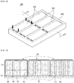
- FIG. 1 is a perspective view of a battery pack 100 according to an embodiment of the present disclosure.
- a battery pack 100 includes a battery module 200 and a pack frame 400 accommodating the battery module 200.
- a battery module 200 includes six battery modules 200 and a pack frame 400 accommodating the battery module 200.
- the number of the battery modules is not limited, and one or more battery modules 200 may be accommodated in the pack frame 400, if necessary.
- FIG. 2 is a cross-sectional view taken along line A-A' of FIG. 1 .
- the battery module 200 includes a cell stack 300 in which one or more battery cells 310 are stacked, and a module frame 210 accommodating the cell stack 300.
- a thermally conductive resin layer 500 is located between the pack frame 400 and the lower surface of the module frame 210, and an open portion 240 is formed on the lower surface of the module frame 210, so the cell stack 300 may make contact with the thermally conductive resin layer 500.
- a heat sink 600 may be located between the thermally conductive resin layer 500 and a bottom portion of the pack frame 400.
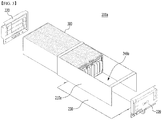
- FIGS. 3 and 4 are exploded perspective views of battery modules 200a and 200b applicable to embodiments of the present disclosure.
- FIG. 3 is an exploded perspective view of a battery module 200a including a U-shaped frame 210a
- FIG. 4 is an exploded perspective view of a battery module 200b including a mono frame 210b.
- both FIG. 3 and FIG. 4 show a state in which the battery modules 200a and 200b are turned over such that the bottom surfaces is looking upward, for convenience of description.
- the module frame 210 of FIG. 2 is a metal plate, and a U-shaped frame or a mono frame may be applied, and the battery module 200a of FIG. 3 is when a U-shaped frame is applied, and the battery module 200b of FIG. 4 is when a mono frame is applied.
- the battery module 200a may include a U-shaped frame 210a accommodating the cell stack 300.
- the U-shaped frame 210a has a form in which an upper surface, a front surface, and a rear surface are opened, and a cover 230 may be connected to the open surface, and an end plate 220 may be connected to the open front and rear surfaces.
- the open portion 240a is formed on the lower surface of the U-shaped frame 210a so that the cell stack 300 is exposed through the open portion 240a.
- the battery module 200b of the present embodiment may include a mono frame 210b accommodating the cell stack 300.
- the mono frame 210b has a form in which front and rear surfaces are opened, and an end plate 220 may be connected to the open front and rear surfaces.
- an open portion 240b is formed on the lower surface of the mono frame 210b so that the cell stack 300 is exposed through the open portion 240b.
- the cell stack 300 is in contact with the thermally conductive resin layer 500.
- Heat generated from the battery cell 310 of the cell stack 300 may be transferred through the thermally conductive resin layer 500 and the heat sink 600 located under the thermally conductive resin layer 500.
- a heat transfer member such as the thermally conductive resin layer 500 is doubly arranged between the cell stack 300 and the module frame 210, and between the module frame 210 and the heat sink 600. This is because all air gaps between the battery cell and the battery module, and the battery module and the battery pack must be removed for heat transfer.
- the open portions 240, 240a, and 240b are formed, it is not necessary to doubly arrange the thermally conductive resin layer 500. Accordingly, cost can be reduced, and quality inspection of the interface of the heat transfer member can be reduced to one, thereby simplifying the process, and reducing process cost are also possible.
- the height of the battery pack 100 may be reduced compared to when the thermally conductive resin layers are doubly arranged.
- the battery pack 100 according to the present embodiment has the advantage of reducing the height limitation.
- the open portions 240, 240a, 240b are not formed, since double heat transfer members are located between the cell stack 300 and the heat sink 600, and a module frame is located between the double heat transfer members, it is difficult to effectively transfer heat generated from the battery cell 310. This is because the module frame itself may deteriorate the heat conduction properties, and a fine air layer that may be formed between the module frame and the double heat transfer member may also be a factor of deteriorating the heat conduction properties.
- the open portions 240, 240a, and 240b in the present embodiment can simplify the heat transfer path between the cell stack 300 and the heat sink 600 into a single thermally conductive resin layer 500, it is possible to increase the cooling performance of the battery pack 100.
- Such a principle can be applied similarly even when the thermally conductive resin layer 500 is in direct contact with the bottom of the pack frame 400, without the configuration of the heat sink 600.
- FIG. 5 is a perspective view of the battery module 200a of FIG. 3 . However, unlike FIG. 3 , FIG. 5 shows a combined state in which the upper surface is looking upward without being turned over.
- a cover 230 may be connected to the open upper surface of the U-shaped frame 210a, and the cover 230 may have a single plate-shaped structure.
- the U-shaped frame 210a and the cover 230 may form a structure surrounding the cell stack 300 by being connected by welding or the like, in a state in which corresponding corner portions are in contact with each other. That is, the U-shaped frame 210a and the cover 230 may have a connection portion CP formed at an edge portion corresponding to each other by a coupling method such as welding.
- the thermally conductive resin layer 500 in the present embodiment may include a thermal resin, and in particular, may include a thermally conductive adhesive material.
- a thermal resin may include at least one of a silicone-based material, a urethane-based material, and an acrylic-based material, and in particular, it is preferable to include a urethane-based material.
- the thermally conductive resin layer 500 includes a thermally conductive resin having excellent thermal conductivity, the heat transfer amount and heat transfer rate between the cell stack 300 and the heat sink 600 may be further increased.
- the thermally conductive resin includes a thermally conductive adhesive material, which may be a material that is a liquid when applied, but solidifies after the cell stack 300 is stacked thereon through the open portions 240, 240a, 240b. Accordingly, the thermally conductive resin layer 500 may fix the cell stack 300 and the battery modules 200, 200a and 200b including the same, within the battery pack 100. That is, the thermally conductive resin layer 500 in the present embodiment not only improves heat dissipation properties for the cell stack 300 through the open portions 240, 240a, 240b, but also has the effect of effectively fixing the cell stack 300.
- the thermally conductive resin layer 500 has a peel strength of 400 g/cm or more when a peel test is performed. Further, it is preferable to have an adhesive strength of 1.4 MPa or more when a shear strength test is performed.
- fastening structures such as hooks or bolts may be formed at four corners (black arrows) of the battery module 200. This is to ensure safety against vibration or impact when the battery module 200 is applied to a device to be described later.
- a fastening structure such as a hook structure or a bolt may be located only at two or one of the four corners (black arrows) of the battery module 200, and in some cases, it is also possible to fix the battery module 200 only with the thermally conductive resin layer 500 without the fastening structure.
- the pack frame 400 may further include a partition wall 410 formed between side surfaces of the battery modules 200.
- a partition wall 410 may support the battery pack 100 from an external impact, and may prevent the flow of the battery modules 200 within the battery pack 100.
- the side surfaces of the battery modules 200 may be in close contact with the partition wall 410 or may be spaced apart at a predetermined interval, but in order to obtain the above effect, it may be more preferable to form a structure in which the side surfaces of the battery modules 200 are in close contact with the partition wall 410 as shown in FIG. 2 .
- FIG. 6 is a cross-sectional view illustrating a battery pack 100a according to another embodiment of the present disclosure.
- the battery pack 100a may form a structure in which side surfaces of the battery modules 200 are in close contact with each other, including a pack frame 400a having no partition walls. That is, among the battery modules, the battery modules 200 arranged along the side direction may have a structure in close contact with each other via the side surfaces.
- FIGS. 1 and 2 Other configurations are the same or similar to those of the battery pack 100 of FIGS. 1 and 2 , so that the cell stack 300 of the battery module 200 is bonded with the thermally conductive resin layer 500a through the open portion 240 formed on the lower surface of the module frame 210, and a heat sink 600a may be located under the thermally conductive resin layer 500a.
- the pack frame 400a is not provided with a partition wall, the battery modules 200 in close contact along the side surfaces may share one thermally conductive resin layer 500a, as shown in FIG. 6 .
- thermally conductive resin layers 500 and 500a of FIGS. 2 and 6 can fix the cell stack 300 or the battery modules 200, 200a, 200b, separate fastening members for fixing such as bolts can be reduced or eliminated. Therefore, instead of the space required for a bolt or nut to be fastened, a structure can be formed in which the battery modules 200 are in close contact with the partition wall 410 as in FIG. 2 , or a structure in which the battery modules 200 are in close contact with each other as in FIG. 6 . Accordingly, since the battery module 200 may be compactly disposed, it may lead to a reduction in the volume of the battery packs 100 and 100a or an increase in battery capacity.
- the battery cell 310 constituting the cell stack 300 are stacked in an upright or inverted manner so as to be parallel to both sides of the module frame 210. Through this, each of the battery cell 310 may be exposed to the open portion 240 to contact the thermally conductive resin layer 500.
- the open portions 240a and 240b may be spaced apart from the front and rear surfaces of the module frames 210a and 210b, respectively. That is, on the lower surfaces of the module frames 210a and 210b, portions in which the open portions 240a and 240b are not formed may be adjacent to the front and rear surfaces of the module frames 210a and 210b, respectively. If the open portions 240a and 240b are formed in all regions of the lower surface, in the process of manufacturing the battery modules 200a and 200b or in the process of assembling the battery pack, there may be a problem that the cell stack 300 or a part thereof is deviated.
- the cell stack 300 can be prevented from being deviated.
- the open portions 240a and 240b may be adjacent to both side surfaces of the module frames 210a and 210b.
- the open portions 240a and 240b must be adjacent to both sides of the module frames 210a and 210b, in order for all of the battery cells including battery cells configuring both ends of the cell stack 300 to be in contact with the thermally conductive resin layer. Effective heat dissipation is possible only when all of the battery cells configuring the cell stack 300 are in contact with the thermally conductive resin layer.
- the above-mentioned battery pack can be applied to various devices.
- a device may be applied to a vehicle such as an electric bicycle, an electric vehicle, or a hybrid vehicle, but the present disclosure is not limited thereto, and is applicable to various devices that can use a battery module.
Landscapes
- Chemical & Material Sciences (AREA)
- Chemical Kinetics & Catalysis (AREA)
- Electrochemistry (AREA)
- General Chemical & Material Sciences (AREA)
- Engineering & Computer Science (AREA)
- Manufacturing & Machinery (AREA)
- Aviation & Aerospace Engineering (AREA)
- Battery Mounting, Suspending (AREA)
- Secondary Cells (AREA)
Applications Claiming Priority (2)
| Application Number | Priority Date | Filing Date | Title |
|---|---|---|---|
| KR1020190075829A KR20210000551A (ko) | 2019-06-25 | 2019-06-25 | 전지 팩 및 이를 포함하는 디바이스 |
| PCT/KR2020/007106 WO2020262832A1 (fr) | 2019-06-25 | 2020-06-02 | Bloc-batterie et dispositif le comprenant |
Publications (2)
| Publication Number | Publication Date |
|---|---|
| EP3926733A1 true EP3926733A1 (fr) | 2021-12-22 |
| EP3926733A4 EP3926733A4 (fr) | 2022-03-30 |
Family
ID=74061014
Family Applications (1)
| Application Number | Title | Priority Date | Filing Date |
|---|---|---|---|
| EP20833499.5A Pending EP3926733A4 (fr) | 2019-06-25 | 2020-06-02 | Bloc-batterie et dispositif le comprenant |
Country Status (6)
| Country | Link |
|---|---|
| US (1) | US20220158270A1 (fr) |
| EP (1) | EP3926733A4 (fr) |
| JP (2) | JP2022521945A (fr) |
| KR (1) | KR20210000551A (fr) |
| CN (1) | CN113748560A (fr) |
| WO (1) | WO2020262832A1 (fr) |
Families Citing this family (8)
| Publication number | Priority date | Publication date | Assignee | Title |
|---|---|---|---|---|
| KR20220101313A (ko) * | 2021-01-11 | 2022-07-19 | 주식회사 엘지에너지솔루션 | 전지 모듈 및 이를 포함하는 전지팩 |
| KR20220101311A (ko) * | 2021-01-11 | 2022-07-19 | 주식회사 엘지에너지솔루션 | 전지 모듈 및 이를 포함하는 전지팩 |
| KR20220101307A (ko) * | 2021-01-11 | 2022-07-19 | 주식회사 엘지에너지솔루션 | 전지 모듈 및 이를 포함하는 전지팩 |
| KR20220101308A (ko) * | 2021-01-11 | 2022-07-19 | 주식회사 엘지에너지솔루션 | 전지 모듈, 이를 포함하는 전지팩 및 이의 제조 방법 |
| KR20220101306A (ko) * | 2021-01-11 | 2022-07-19 | 주식회사 엘지에너지솔루션 | 전지 모듈 및 이를 포함하는 전지팩 |
| KR20220140244A (ko) * | 2021-04-09 | 2022-10-18 | 주식회사 엘지에너지솔루션 | 전지팩 및 이를 포함하는 디바이스 |
| US20240088500A1 (en) * | 2021-04-23 | 2024-03-14 | Lg Energy Solution, Ltd. | Battery Module and Battery Pack Including the Same |
| KR20240000975A (ko) * | 2022-06-24 | 2024-01-03 | 주식회사 엘지에너지솔루션 | 전지 모듈 |
Family Cites Families (21)
| Publication number | Priority date | Publication date | Assignee | Title |
|---|---|---|---|---|
| FR2924857B1 (fr) * | 2007-12-06 | 2014-06-06 | Valeo Equip Electr Moteur | Dispositif d'alimentation electrique comportant un bac de reception d'unites de stockage a ultra capacite |
| US20120141851A1 (en) * | 2010-12-06 | 2012-06-07 | Suyu Hou | System and method for enclosing an energy storage device |
| WO2012133707A1 (fr) * | 2011-03-31 | 2012-10-04 | 三洋電機株式会社 | Dispositif de source d'alimentation et véhicule comportant un dispositif de source d'alimentation |
| US20140023906A1 (en) * | 2011-03-31 | 2014-01-23 | Hiroyuki Hashimoto | Power supply apparatus and vehicle having the same |
| KR101255241B1 (ko) * | 2011-04-12 | 2013-04-16 | 삼성에스디아이 주식회사 | 배터리 모듈 |
| JP2013012441A (ja) * | 2011-06-30 | 2013-01-17 | Sanyo Electric Co Ltd | 電源装置及び電源装置を備える車両 |
| JP5880847B2 (ja) * | 2012-04-25 | 2016-03-09 | 三菱自動車工業株式会社 | バッテリ装置 |
| JP6192329B2 (ja) * | 2013-03-27 | 2017-09-06 | コベルコ建機株式会社 | 電池冷却構造 |
| KR101636378B1 (ko) * | 2013-08-28 | 2016-07-05 | 주식회사 엘지화학 | 방열 구조를 가지는 단위모듈 제조용 모듈 하우징 및 이를 포함하는 전지모듈 |
| JP6247608B2 (ja) * | 2014-07-23 | 2017-12-13 | 日立オートモティブシステムズ株式会社 | 電池パック |
| US10236134B1 (en) * | 2015-02-26 | 2019-03-19 | Amazon Technologies, Inc. | Battery thermal shield |
| KR101865995B1 (ko) * | 2015-03-27 | 2018-06-08 | 주식회사 엘지화학 | 배터리 모듈 |
| KR102082384B1 (ko) * | 2015-08-11 | 2020-02-27 | 주식회사 엘지화학 | 금속 팩 케이스와 열전도 부재를 포함하는 전지팩 |
| US9865906B2 (en) * | 2016-04-15 | 2018-01-09 | Lg Chem, Ltd. | Battery system and method of assembling the battery system |
| WO2018062172A1 (fr) * | 2016-09-30 | 2018-04-05 | 積水化学工業株式会社 | Composition de résine thermiquement conductrice, thermiquement expansible, corps moulé thermiquement conducteur, thermiquement expansible, module de batterie et bloc-batterie |
| KR102086127B1 (ko) * | 2016-10-31 | 2020-03-06 | 주식회사 엘지화학 | 배터리의 엣지 면에 직접 냉각 방식이 적용된 배터리 팩 |
| DE102016222264A1 (de) * | 2016-11-14 | 2018-05-30 | Robert Bosch Gmbh | Batteriemodul, Verfahren zu dessen Herstellung und Batterie |
| EP3352290A1 (fr) * | 2017-01-19 | 2018-07-25 | 3M Innovative Properties Company | Remplissage d'espace vide thermoconducteur à base d'aziridino polyéther fonctionnel |
| KR102256098B1 (ko) * | 2017-04-06 | 2021-06-03 | 주식회사 엘지에너지솔루션 | 루버 핀 형상의 열전도 매개체를 구비한 배터리 팩 |
| WO2019013508A1 (fr) * | 2017-07-10 | 2019-01-17 | 주식회사 엘지화학 | Boîtier de module de batterie et module de batterie le comprenant |
| JP6922683B2 (ja) * | 2017-11-17 | 2021-08-18 | トヨタ自動車株式会社 | 電池パック、電池パックの製造方法及び介在部材 |
-
2019
- 2019-06-25 KR KR1020190075829A patent/KR20210000551A/ko not_active IP Right Cessation
-
2020
- 2020-06-02 CN CN202080032135.XA patent/CN113748560A/zh active Pending
- 2020-06-02 US US17/435,586 patent/US20220158270A1/en active Pending
- 2020-06-02 EP EP20833499.5A patent/EP3926733A4/fr active Pending
- 2020-06-02 JP JP2021549531A patent/JP2022521945A/ja active Pending
- 2020-06-02 WO PCT/KR2020/007106 patent/WO2020262832A1/fr unknown
-
2023
- 2023-07-20 JP JP2023118508A patent/JP2023143936A/ja active Pending
Also Published As
| Publication number | Publication date |
|---|---|
| CN113748560A (zh) | 2021-12-03 |
| KR20210000551A (ko) | 2021-01-05 |
| US20220158270A1 (en) | 2022-05-19 |
| JP2022521945A (ja) | 2022-04-13 |
| EP3926733A4 (fr) | 2022-03-30 |
| WO2020262832A1 (fr) | 2020-12-30 |
| JP2023143936A (ja) | 2023-10-06 |
Similar Documents
| Publication | Publication Date | Title |
|---|---|---|
| EP3926733A1 (fr) | Bloc-batterie et dispositif le comprenant | |
| KR20180020546A (ko) | 배터리 모듈 | |
| EP3958379B1 (fr) | Module de batterie et bloc-batterie le comprenant | |
| EP4087018A1 (fr) | Bloc-batterie et dispositif le comprenant | |
| EP4016703A1 (fr) | Module de batterie et bloc-batterie le comprenant | |
| EP4181292A1 (fr) | Module de batterie et bloc-batterie le comprenant | |
| EP4181275A1 (fr) | Module de batterie et bloc-batterie le comprenant | |
| EP4254626A1 (fr) | Batterie et dispositif la comprenant | |
| US20230344061A1 (en) | Battery module and battery pack including the same | |
| US20220029250A1 (en) | Battery Module and Battery Pack Including the Same | |
| US20220158284A1 (en) | Battery Module and Battery Pack Including the Same | |
| EP4261985A1 (fr) | Bloc-batterie et dispositif le comprenant | |
| EP4210154A1 (fr) | Bloc-batterie et dispositif le comprenant | |
| EP4175020A1 (fr) | Module de batterie et bloc-batterie le comprenant | |
| US20240136641A1 (en) | Battery pack and device including the same | |
| EP4300686A1 (fr) | Module de batterie et bloc-batterie le comprenant | |
| US20230268584A1 (en) | Battery module and manufacturing method of the same | |
| EP4184666A1 (fr) | Bloc-batterie et dispositif le comprenant | |
| US20240170755A1 (en) | Battery pack and device including the same | |
| US20230318078A1 (en) | Battery module and battery pack including the same | |
| US20230261307A1 (en) | Battery pack and device including the same | |
| US20240106026A1 (en) | Battery module and battery pack including the same | |
| US20230275283A1 (en) | Battery module and battery pack including the same | |
| US20220376327A1 (en) | Battery module and battery pack including the same | |
| EP3843174A1 (fr) | Module de batterie, son procédé de préparation et bloc-batterie le comprenant |
Legal Events
| Date | Code | Title | Description |
|---|---|---|---|
| STAA | Information on the status of an ep patent application or granted ep patent |
Free format text: STATUS: THE INTERNATIONAL PUBLICATION HAS BEEN MADE |
|
| PUAI | Public reference made under article 153(3) epc to a published international application that has entered the european phase |
Free format text: ORIGINAL CODE: 0009012 |
|
| STAA | Information on the status of an ep patent application or granted ep patent |
Free format text: STATUS: REQUEST FOR EXAMINATION WAS MADE |
|
| 17P | Request for examination filed |
Effective date: 20210917 |
|
| AK | Designated contracting states |
Kind code of ref document: A1 Designated state(s): AL AT BE BG CH CY CZ DE DK EE ES FI FR GB GR HR HU IE IS IT LI LT LU LV MC MK MT NL NO PL PT RO RS SE SI SK SM TR |
|
| A4 | Supplementary search report drawn up and despatched |
Effective date: 20220301 |
|
| RAP3 | Party data changed (applicant data changed or rights of an application transferred) |
Owner name: LG ENERGY SOLUTION, LTD. |
|
| RIC1 | Information provided on ipc code assigned before grant |
Ipc: H01M 10/613 20140101ALI20220223BHEP Ipc: H01M 10/625 20140101ALI20220223BHEP Ipc: H01M 10/655 20140101ALI20220223BHEP Ipc: H01M 10/653 20140101AFI20220223BHEP |
|
| DAV | Request for validation of the european patent (deleted) | ||
| DAX | Request for extension of the european patent (deleted) |