EP3926730A1 - Battery module - Google Patents
Battery module Download PDFInfo
- Publication number
- EP3926730A1 EP3926730A1 EP20861658.1A EP20861658A EP3926730A1 EP 3926730 A1 EP3926730 A1 EP 3926730A1 EP 20861658 A EP20861658 A EP 20861658A EP 3926730 A1 EP3926730 A1 EP 3926730A1
- Authority
- EP
- European Patent Office
- Prior art keywords
- battery module
- thermal conduction
- conduction plate
- sensing element
- batteries
- Prior art date
- Legal status (The legal status is an assumption and is not a legal conclusion. Google has not performed a legal analysis and makes no representation as to the accuracy of the status listed.)
- Granted
Links
- 230000004308 accommodation Effects 0.000 claims description 31
- 238000002955 isolation Methods 0.000 claims description 15
- 238000005070 sampling Methods 0.000 abstract description 6
- 239000000853 adhesive Substances 0.000 description 4
- 230000001070 adhesive effect Effects 0.000 description 4
- 238000000034 method Methods 0.000 description 3
- 238000004806 packaging method and process Methods 0.000 description 3
- XAGFODPZIPBFFR-UHFFFAOYSA-N aluminium Chemical compound [Al] XAGFODPZIPBFFR-UHFFFAOYSA-N 0.000 description 2
- 229910052782 aluminium Inorganic materials 0.000 description 2
- 238000012986 modification Methods 0.000 description 2
- 230000004048 modification Effects 0.000 description 2
- 230000009286 beneficial effect Effects 0.000 description 1
- 239000004020 conductor Substances 0.000 description 1
- 238000010586 diagram Methods 0.000 description 1
- 238000004146 energy storage Methods 0.000 description 1
- 230000017525 heat dissipation Effects 0.000 description 1
- 238000010438 heat treatment Methods 0.000 description 1
- 239000000463 material Substances 0.000 description 1
- 239000004033 plastic Substances 0.000 description 1
- 239000002985 plastic film Substances 0.000 description 1
- 229920006255 plastic film Polymers 0.000 description 1
Images


Classifications
-
- H—ELECTRICITY
- H01—ELECTRIC ELEMENTS
- H01M—PROCESSES OR MEANS, e.g. BATTERIES, FOR THE DIRECT CONVERSION OF CHEMICAL ENERGY INTO ELECTRICAL ENERGY
- H01M10/00—Secondary cells; Manufacture thereof
- H01M10/60—Heating or cooling; Temperature control
- H01M10/65—Means for temperature control structurally associated with the cells
- H01M10/655—Solid structures for heat exchange or heat conduction
- H01M10/6554—Rods or plates
- H01M10/6555—Rods or plates arranged between the cells
-
- H—ELECTRICITY
- H01—ELECTRIC ELEMENTS
- H01M—PROCESSES OR MEANS, e.g. BATTERIES, FOR THE DIRECT CONVERSION OF CHEMICAL ENERGY INTO ELECTRICAL ENERGY
- H01M10/00—Secondary cells; Manufacture thereof
- H01M10/42—Methods or arrangements for servicing or maintenance of secondary cells or secondary half-cells
- H01M10/48—Accumulators combined with arrangements for measuring, testing or indicating the condition of cells, e.g. the level or density of the electrolyte
- H01M10/486—Accumulators combined with arrangements for measuring, testing or indicating the condition of cells, e.g. the level or density of the electrolyte for measuring temperature
-
- H—ELECTRICITY
- H01—ELECTRIC ELEMENTS
- H01M—PROCESSES OR MEANS, e.g. BATTERIES, FOR THE DIRECT CONVERSION OF CHEMICAL ENERGY INTO ELECTRICAL ENERGY
- H01M10/00—Secondary cells; Manufacture thereof
- H01M10/60—Heating or cooling; Temperature control
- H01M10/61—Types of temperature control
- H01M10/613—Cooling or keeping cold
-
- H—ELECTRICITY
- H01—ELECTRIC ELEMENTS
- H01M—PROCESSES OR MEANS, e.g. BATTERIES, FOR THE DIRECT CONVERSION OF CHEMICAL ENERGY INTO ELECTRICAL ENERGY
- H01M10/00—Secondary cells; Manufacture thereof
- H01M10/60—Heating or cooling; Temperature control
- H01M10/64—Heating or cooling; Temperature control characterised by the shape of the cells
- H01M10/647—Prismatic or flat cells, e.g. pouch cells
-
- H—ELECTRICITY
- H01—ELECTRIC ELEMENTS
- H01M—PROCESSES OR MEANS, e.g. BATTERIES, FOR THE DIRECT CONVERSION OF CHEMICAL ENERGY INTO ELECTRICAL ENERGY
- H01M10/00—Secondary cells; Manufacture thereof
- H01M10/60—Heating or cooling; Temperature control
- H01M10/65—Means for temperature control structurally associated with the cells
- H01M10/653—Means for temperature control structurally associated with the cells characterised by electrically insulating or thermally conductive materials
-
- H—ELECTRICITY
- H01—ELECTRIC ELEMENTS
- H01M—PROCESSES OR MEANS, e.g. BATTERIES, FOR THE DIRECT CONVERSION OF CHEMICAL ENERGY INTO ELECTRICAL ENERGY
- H01M10/00—Secondary cells; Manufacture thereof
- H01M10/60—Heating or cooling; Temperature control
- H01M10/65—Means for temperature control structurally associated with the cells
- H01M10/655—Solid structures for heat exchange or heat conduction
- H01M10/6554—Rods or plates
-
- H—ELECTRICITY
- H01—ELECTRIC ELEMENTS
- H01M—PROCESSES OR MEANS, e.g. BATTERIES, FOR THE DIRECT CONVERSION OF CHEMICAL ENERGY INTO ELECTRICAL ENERGY
- H01M50/00—Constructional details or processes of manufacture of the non-active parts of electrochemical cells other than fuel cells, e.g. hybrid cells
- H01M50/20—Mountings; Secondary casings or frames; Racks, modules or packs; Suspension devices; Shock absorbers; Transport or carrying devices; Holders
- H01M50/204—Racks, modules or packs for multiple batteries or multiple cells
- H01M50/207—Racks, modules or packs for multiple batteries or multiple cells characterised by their shape
- H01M50/209—Racks, modules or packs for multiple batteries or multiple cells characterised by their shape adapted for prismatic or rectangular cells
-
- H—ELECTRICITY
- H01—ELECTRIC ELEMENTS
- H01M—PROCESSES OR MEANS, e.g. BATTERIES, FOR THE DIRECT CONVERSION OF CHEMICAL ENERGY INTO ELECTRICAL ENERGY
- H01M50/00—Constructional details or processes of manufacture of the non-active parts of electrochemical cells other than fuel cells, e.g. hybrid cells
- H01M50/20—Mountings; Secondary casings or frames; Racks, modules or packs; Suspension devices; Shock absorbers; Transport or carrying devices; Holders
- H01M50/262—Mountings; Secondary casings or frames; Racks, modules or packs; Suspension devices; Shock absorbers; Transport or carrying devices; Holders with fastening means, e.g. locks
- H01M50/264—Mountings; Secondary casings or frames; Racks, modules or packs; Suspension devices; Shock absorbers; Transport or carrying devices; Holders with fastening means, e.g. locks for cells or batteries, e.g. straps, tie rods or peripheral frames
-
- H—ELECTRICITY
- H01—ELECTRIC ELEMENTS
- H01M—PROCESSES OR MEANS, e.g. BATTERIES, FOR THE DIRECT CONVERSION OF CHEMICAL ENERGY INTO ELECTRICAL ENERGY
- H01M50/00—Constructional details or processes of manufacture of the non-active parts of electrochemical cells other than fuel cells, e.g. hybrid cells
- H01M50/20—Mountings; Secondary casings or frames; Racks, modules or packs; Suspension devices; Shock absorbers; Transport or carrying devices; Holders
- H01M50/289—Mountings; Secondary casings or frames; Racks, modules or packs; Suspension devices; Shock absorbers; Transport or carrying devices; Holders characterised by spacing elements or positioning means within frames, racks or packs
- H01M50/291—Mountings; Secondary casings or frames; Racks, modules or packs; Suspension devices; Shock absorbers; Transport or carrying devices; Holders characterised by spacing elements or positioning means within frames, racks or packs characterised by their shape
-
- H—ELECTRICITY
- H01—ELECTRIC ELEMENTS
- H01M—PROCESSES OR MEANS, e.g. BATTERIES, FOR THE DIRECT CONVERSION OF CHEMICAL ENERGY INTO ELECTRICAL ENERGY
- H01M50/00—Constructional details or processes of manufacture of the non-active parts of electrochemical cells other than fuel cells, e.g. hybrid cells
- H01M50/20—Mountings; Secondary casings or frames; Racks, modules or packs; Suspension devices; Shock absorbers; Transport or carrying devices; Holders
- H01M50/298—Mountings; Secondary casings or frames; Racks, modules or packs; Suspension devices; Shock absorbers; Transport or carrying devices; Holders characterised by the wiring of battery packs
-
- H—ELECTRICITY
- H01—ELECTRIC ELEMENTS
- H01M—PROCESSES OR MEANS, e.g. BATTERIES, FOR THE DIRECT CONVERSION OF CHEMICAL ENERGY INTO ELECTRICAL ENERGY
- H01M50/00—Constructional details or processes of manufacture of the non-active parts of electrochemical cells other than fuel cells, e.g. hybrid cells
- H01M50/50—Current conducting connections for cells or batteries
- H01M50/502—Interconnectors for connecting terminals of adjacent batteries; Interconnectors for connecting cells outside a battery casing
- H01M50/505—Interconnectors for connecting terminals of adjacent batteries; Interconnectors for connecting cells outside a battery casing comprising a single busbar
-
- H—ELECTRICITY
- H01—ELECTRIC ELEMENTS
- H01M—PROCESSES OR MEANS, e.g. BATTERIES, FOR THE DIRECT CONVERSION OF CHEMICAL ENERGY INTO ELECTRICAL ENERGY
- H01M2200/00—Safety devices for primary or secondary batteries
- H01M2200/10—Temperature sensitive devices
- H01M2200/105—NTC
-
- Y—GENERAL TAGGING OF NEW TECHNOLOGICAL DEVELOPMENTS; GENERAL TAGGING OF CROSS-SECTIONAL TECHNOLOGIES SPANNING OVER SEVERAL SECTIONS OF THE IPC; TECHNICAL SUBJECTS COVERED BY FORMER USPC CROSS-REFERENCE ART COLLECTIONS [XRACs] AND DIGESTS
- Y02—TECHNOLOGIES OR APPLICATIONS FOR MITIGATION OR ADAPTATION AGAINST CLIMATE CHANGE
- Y02E—REDUCTION OF GREENHOUSE GAS [GHG] EMISSIONS, RELATED TO ENERGY GENERATION, TRANSMISSION OR DISTRIBUTION
- Y02E60/00—Enabling technologies; Technologies with a potential or indirect contribution to GHG emissions mitigation
- Y02E60/10—Energy storage using batteries
Definitions
- the present application relates to the field of traction batteries, and in particular, to a battery module.
- a temperature sensing element such as a NTC thermistor
- a connecting plate which is located above batteries and connects electrode terminals of adjacent batteries.
- This method has the following problems: a tab of a soft pack battery is thin, and it is difficult to dissipate heat; in addition, overcurrent through the connecting plate is relatively large when the battery module is in a large current working condition, so that an acquired temperature is higher than an actual temperature of the batteries.
- the other is to directly fasten the temperature sensing element to the batteries by using an adhesive.
- This method has the following problems: due to the impact of the temperature and battery expansion (the performance of the adhesive deteriorates), when the battery module is used for a long time, the reliability of a connection between the thermistor and the batteries deteriorates; this results in a large deviation between the temperature acquired by the temperature sensing element and the actual temperature of the batteries.
- an objective of the embodiments of the present application is to provide a battery module and a device, which can reduce a deviation between a temperature acquired by a temperature sensing element and an actual temperature of batteries, and improve the reliability and accuracy of temperature sampling of the battery module.
- the battery module includes a plurality of batteries, a thermal conduction plate, and a temperature sensing element.
- the plurality of batteries are arranged in a length direction.
- the thermal conduction plate is located between the adjacent batteries and fits the batteries.
- the temperature sensing element is in contact with the thermal conduction plate.
- the battery module further includes a fastening holder.
- the fastening holder includes a surrounding wall and a hollow cavity encircled by the surrounding wall. An inner side surface of the surrounding wall is provided with a limiting groove connecting with the hollow cavity.
- the thermal conduction plate is inserted into the limiting groove and seals the hollow cavity.
- the temperature sensing element is fastened to the surrounding wall of the fastening holder.
- the surrounding wall is provided with an aperture.
- the thermal conduction plate has an exposed part exposed from the aperture.
- the temperature sensing element is in contact with the exposed part of the thermal conduction plate.
- the surrounding wall is provided with an accommodation groove.
- the aperture is located inside the accommodation groove.
- the temperature sensing element is fastened to the accommodation groove and in contact with the exposed part of the thermal conduction plate.
- the surrounding wall is composed of a top wall, a bottom wall, and two side walls.
- the accommodation groove is recessed inward relative to a surface of the top wall in the length direction.
- the accommodation groove is located at one end of the top wall in a width direction.
- the accommodation groove includes a first portion and a second portion.
- the first portion extends in the width direction, and the aperture is located inside the first portion.
- the second portion is connected to the first portion and extends from the first portion in a height direction.
- the battery module further includes an isolation board, an acquisition line, and a plug connector.
- the isolation board is disposed above a corresponding battery.
- One end of the acquisition line is connected to the temperature sensing element.
- the other end of the acquisition line is connected to the plug connector.
- the plug connector is connected to a circuit board. A portion of the acquisition line being connected to the temperature sensing element is accommodated in the accommodation groove.
- the isolation board is provided with a buckle.
- the acquisition line is fastened on the isolation board through the buckle.
- the top wall of the fastening holder is provided with a cabling groove with an upward opening.
- the cabling groove communicates with the second portion of the accommodation groove.
- the acquisition line passes through the cabling groove.
- the limiting groove includes a first limiting groove formed in the top wall, the bottom wall, and one of the side walls, and a second limiting groove formed in the other side wall.
- the second limiting groove extends through the other side wall in the width direction.
- the thermal conduction plate includes a body portion and a bent portion.
- the bent portion is connected to the body portion and bent from the body portion in the length direction.
- the second limiting groove extends through the side wall of the fastening holder being away from the accommodation groove in the width direction.
- the body portion is inserted into the fastening holder via the second limiting groove.
- the bent portion is located on an outer side of the fastening holder in the length direction.
- the thermal conduction plate fits the batteries. Heat generated by the batteries is transferred to the thermal conduction plate, and then transferred to the outside via the thermal conduction plate.
- the temperature sensing element is in contact with the thermal conduction plate to acquire a temperature of the batteries. Because the temperature of the batteries that is acquired by the temperature sensing element via the thermal conduction plate is close to an actual temperature of the batteries, a deviation between the temperature acquired by the temperature sensing element and the actual temperature of the batteries can be reduced, and the reliability and accuracy of temperature sampling of the battery module can be improved.
- connection may be a fixed connection, a removable connection, or an integral connection; may be an electrical connection or a signal connection; the “connection” may be a direct connection or an indirect connection by using an intermediate medium.
- the battery module in the present application includes a plurality of batteries 1, a thermal conduction plate 2, and a temperature sensing element 3.
- the plurality of batteries 1 of the battery module are arranged in a length direction L.
- the thermal conduction plate 2 is located between the adjacent batteries 1 and fits the batteries 1.
- the temperature sensing element 3 is in contact with the thermal conduction plate 2.
- the battery module may further include a fastening holder 4, an isolation board 5, an acquisition line 6, and a plug connector 7.
- the thermal conduction plate 2 fits the batteries 1. Heat generated by the batteries 1 is transferred to the thermal conduction plate 2, and then transferred to the outside via the thermal conduction plate 2.
- the temperature sensing element 3 is in contact with the thermal conduction plate 2 to acquire a temperature of the batteries 1. Because the temperature of the batteries 1 that is acquired by the temperature sensing element 3 via the thermal conduction plate 2 is close to an actual temperature of the batteries 1, a deviation between the temperature acquired by the temperature sensing element 3 and the actual temperature of the batteries can be reduced, and the reliability and accuracy of temperature sampling of the battery module can be improved.
- the batteries 1 are soft pack batteries (or referred to as bag batteries).
- the soft pack battery includes a packaging bag (for example, formed by an aluminum plastic film), an electrode assembly, and a tab 11.
- the electrode assembly includes a positive electrode plate, a negative electrode plate, and a separator film that separates the positive electrode plate and the negative electrode plate.
- a part of the tab is packaged in the packaging bag and the other part extends out of the packaging bag.
- the tab 11 may be directly formed by the electrode plate or use an independent conductive material and be electrically connected to a current collector.
- the thermal conduction plate 2 is an aluminum plate.
- the thermal conduction plate 2 includes a body portion 22 and a bent portion 23.
- the bent portion 23 is connected to the body portion 22 and bent from the body portion 22 in the length direction L.
- the temperature sensing element 3 is an NTC thermistor and configured to acquire a temperature.
- the temperature sensing element 3 may be fastened by using the fastening holder 4.
- a material of the fastening holder 4 is plastic.
- the fastening holder 4 includes a surrounding wall 41 and a hollow cavity 42 encircled by the surrounding wall 41.
- the surrounding wall 41 is composed of a top wall 41b, a bottom wall 41c, and two side walls 41d.
- An inner side surface 41a of the surrounding wall 41 is provided with a limiting groove 411 connecting with the hollow cavity 42.
- the thermal conduction plate 2 is inserted into the limiting groove 411 and seals the hollow cavity 42.
- the temperature sensing element 3 is fastened to the surrounding wall 41 of the fastening holder 4. In this way, the temperature sensing element 3 is fastened.
- the surrounding wall 41 is provided with an aperture 412.
- the thermal conduction plate 2 has an exposed part 21 exposed from the aperture 412.
- the temperature sensing element 3 is in contact with the exposed part 21 of the thermal conduction plate 2.
- the surrounding wall 41 is provided with an accommodation groove 413.
- the aperture 412 is located inside the accommodation groove 413.
- the temperature sensing element 3 is fastened to the accommodation groove 413 and in contact with the exposed part 21 of the thermal conduction plate 2. Therefore, the temperature sensing element 3 does not need to occupy additional space. This increases energy density of the battery module.
- the accommodation groove 413 is recessed inward relative to a surface of the top wall 41b in the length direction L.
- the accommodation groove 413 is preferably located at one end of the top wall 41b in a width direction W.
- the temperature sensing element 3 is preferably disposed at one end of the top wall 41b in the width direction W. At this position, the temperature acquired by the temperature sensing element 3 is the closest to the actual temperature of the batteries 1. Because a position close to the middle of the top wall 41b in the width direction W is seriously affected by heating at a position of the tab 11 of the battery 1, the temperature actually acquired by the temperature sensing element 3 is relatively high.
- the limiting groove 411 includes a first limiting groove 411a formed in the top wall 41b, the bottom wall 41c, and one of the side walls, and a second limiting groove 411b formed in the other side wall 41d.
- the second limiting groove 411b extends through the other side wall 41d in the width direction W.
- the second limiting groove 411b preferably extends through the side wall 41d of the fastening holder 4 being away from the accommodation groove 413 in the width direction W, to prevent the second limiting groove 411b from affecting temperature acquisition of the temperature sensing element 3.
- the body portion 22 of the thermal conduction plate 2 is inserted into the fastening holder 4 via the second limiting groove 411b.
- the bent portion 23 is located on an outer side of the fastening holder 4 in the length direction L. In this way, the thermal conduction plate 2 is mounted to the fastening holder 4.
- the accommodation groove 413 includes a first portion 413a and a second portion 413b.
- the first portion 413a extends in the width direction W, and the aperture 412 is located inside the first portion 413a.
- the second portion 413b is connected to the first portion 413a and extends from the first portion 413a in a height direction H.
- the structure of the accommodation groove 413 is not limited thereto.
- a thermally conductive adhesive may be used to fasten the temperature sensing element 3 to the first portion 413a of the accommodation groove 413.
- the isolation board 5 is disposed above a corresponding battery 1.
- the isolation board 5 includes a through groove 52 in the height direction H.
- the tab 11 passes through the through groove 52.
- one end of the acquisition line 6 is connected to the temperature sensing element 3.
- the other end of the acquisition line 6 is connected to the plug connector 7.
- the plug connector 7 is connected to a circuit board (not shown). This implements an entire temperature sampling circuit of the battery module.
- a portion of the acquisition line 6 being connected to the temperature sensing element 3 is accommodated in the accommodation groove 413 to facilitate cabling.
- the portion of the acquisition line 6 being connected to the temperature sensing element 3 may be accommodated in the second portion 413b of the accommodation groove 413.
- the isolation board 5 is provided with a buckle 51.
- the acquisition line 6 is fastened on the isolation board 5 through the buckle 51.
- the acquisition line 6 is fastened through the buckle 51 to reduce the pulling of the acquisition line 6 on the temperature sensing element 3 during vibration and impact. This can improve the reliability of the contact between the temperature sensing element 3 and the thermal conduction plate 2.
- the top wall 41b of the fastening holder 4 is provided with a cabling groove R with an upward opening.
- the cabling groove R communicates with the second portion 413b of the accommodation groove 413.
- the acquisition line 6 passes through the cabling groove R.
- the acquisition line 6 can be fastened in a direction of the cabling groove R and the second portion 413b by using the thermally conductive adhesive.
- An embodiment of the present application further provides a device, including the battery module described in the foregoing embodiments.
- the battery module is configured to provide electric energy.
- the device may be a vehicle or an energy storage device.
Landscapes
- Chemical & Material Sciences (AREA)
- Chemical Kinetics & Catalysis (AREA)
- Electrochemistry (AREA)
- General Chemical & Material Sciences (AREA)
- Engineering & Computer Science (AREA)
- Manufacturing & Machinery (AREA)
- Battery Mounting, Suspending (AREA)
- Secondary Cells (AREA)
Abstract
Description
- The present application claims priority to
Chinese Patent Application No. 201921478827.8 filed with the China National Intellectual Property Administration on September 6, 2019 - The present application relates to the field of traction batteries, and in particular, to a battery module.
- At present, there are two temperature sampling methods for soft pack battery modules. One is to dispose a temperature sensing element (such as a NTC thermistor) on a connecting plate (which is located above batteries and connects electrode terminals of adjacent batteries). This method has the following problems: a tab of a soft pack battery is thin, and it is difficult to dissipate heat; in addition, overcurrent through the connecting plate is relatively large when the battery module is in a large current working condition, so that an acquired temperature is higher than an actual temperature of the batteries. The other is to directly fasten the temperature sensing element to the batteries by using an adhesive. This method has the following problems: due to the impact of the temperature and battery expansion (the performance of the adhesive deteriorates), when the battery module is used for a long time, the reliability of a connection between the thermistor and the batteries deteriorates; this results in a large deviation between the temperature acquired by the temperature sensing element and the actual temperature of the batteries.
- In view of the disadvantages in the prior art, an objective of the embodiments of the present application is to provide a battery module and a device, which can reduce a deviation between a temperature acquired by a temperature sensing element and an actual temperature of batteries, and improve the reliability and accuracy of temperature sampling of the battery module.
- In order to achieve the foregoing objective, embodiments of the present application provide a battery module. The battery module includes a plurality of batteries, a thermal conduction plate, and a temperature sensing element. The plurality of batteries are arranged in a length direction. The thermal conduction plate is located between the adjacent batteries and fits the batteries. The temperature sensing element is in contact with the thermal conduction plate.
- In an embodiment, the battery module further includes a fastening holder. The fastening holder includes a surrounding wall and a hollow cavity encircled by the surrounding wall. An inner side surface of the surrounding wall is provided with a limiting groove connecting with the hollow cavity. The thermal conduction plate is inserted into the limiting groove and seals the hollow cavity. The temperature sensing element is fastened to the surrounding wall of the fastening holder.
- In an embodiment, the surrounding wall is provided with an aperture. The thermal conduction plate has an exposed part exposed from the aperture. The temperature sensing element is in contact with the exposed part of the thermal conduction plate.
- In an embodiment, the surrounding wall is provided with an accommodation groove. The aperture is located inside the accommodation groove. The temperature sensing element is fastened to the accommodation groove and in contact with the exposed part of the thermal conduction plate.
- In an embodiment, the surrounding wall is composed of a top wall, a bottom wall, and two side walls. The accommodation groove is recessed inward relative to a surface of the top wall in the length direction. The accommodation groove is located at one end of the top wall in a width direction.
- In an embodiment, the accommodation groove includes a first portion and a second portion. The first portion extends in the width direction, and the aperture is located inside the first portion. The second portion is connected to the first portion and extends from the first portion in a height direction.
- In an embodiment, the battery module further includes an isolation board, an acquisition line, and a plug connector. The isolation board is disposed above a corresponding battery. One end of the acquisition line is connected to the temperature sensing element. The other end of the acquisition line is connected to the plug connector. The plug connector is connected to a circuit board. A portion of the acquisition line being connected to the temperature sensing element is accommodated in the accommodation groove.
- In an embodiment, the isolation board is provided with a buckle. The acquisition line is fastened on the isolation board through the buckle. The top wall of the fastening holder is provided with a cabling groove with an upward opening. The cabling groove communicates with the second portion of the accommodation groove. The acquisition line passes through the cabling groove.
- In an embodiment, the limiting groove includes a first limiting groove formed in the top wall, the bottom wall, and one of the side walls, and a second limiting groove formed in the other side wall. The second limiting groove extends through the other side wall in the width direction.
- In an embodiment, the thermal conduction plate includes a body portion and a bent portion. The bent portion is connected to the body portion and bent from the body portion in the length direction. The second limiting groove extends through the side wall of the fastening holder being away from the accommodation groove in the width direction. The body portion is inserted into the fastening holder via the second limiting groove. The bent portion is located on an outer side of the fastening holder in the length direction.
- Beneficial effects of the present application are as follows:
In the battery module in the embodiments of the present application, the thermal conduction plate fits the batteries. Heat generated by the batteries is transferred to the thermal conduction plate, and then transferred to the outside via the thermal conduction plate. The temperature sensing element is in contact with the thermal conduction plate to acquire a temperature of the batteries. Because the temperature of the batteries that is acquired by the temperature sensing element via the thermal conduction plate is close to an actual temperature of the batteries, a deviation between the temperature acquired by the temperature sensing element and the actual temperature of the batteries can be reduced, and the reliability and accuracy of temperature sampling of the battery module can be improved. -
-
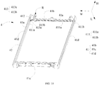
FIG. 1 is a stereograph of a battery module provided by an embodiment of the present application; -
FIG. 2 is a top view of a battery module provided by an embodiment of the present application; -
FIG. 3 is a partial stereoscopic view of a battery module provided by an embodiment of the present application; -
FIG. 4 is an exploded stereoscopic view of the battery module inFIG. 3 ; -
FIG. 5 is a partial stereoscopic view of a battery module from another angle of view provided by an embodiment of the present application; -
FIG. 6 is a front view of the battery module inFIG. 3 , in which an isolation board is not shown; -
FIG. 7 is a stereoscopic view of assembly of a fastening holder and a thermal conduction plate of a battery module provided by an embodiment of the present application; -
FIG. 8 is a schematic diagram of assembly of a fastening holder and a thermal conduction plate of a battery module provided by an embodiment of the present application; -
FIG. 9 is an exploded stereoscopic view of a fastening holder and a thermal conduction plate of a battery module provided by an embodiment of the present application; -
FIG. 10 is a stereoscopic view of a fastening holder of a battery module from an angle of view provided by an embodiment of the present application; -
FIG. 11 is a stereoscopic view of a fastening holder of a battery module from another angle of view provided by an embodiment of the present application; and -
FIG. 12 is a stereoscopic view of a fastening holder of a battery module from still another angle of view provided by an embodiment of the present application. -
- 1:
- Battery;
- 11:
- Tab;
- 2:
- Thermal conduction plate;
- 21:
- Exposed part;
- 22:
- Body portion;
- 23:
- Bent portion;
- 3:
- Temperature sensing element;
- 4:
- Fastening holder;
- 41:
- Surrounding wall;
- 41a:
- Inner side surface;
- 41b:
- Top wall;
- 41c:
- Bottom wall;
- 41d:
- Side wall;
- 411:
- Limiting groove;
- 411a:
- First limiting groove;
- 411b:
- Second limiting groove;
- 412:
- Aperture;
- 413:
- Accommodation groove;
- 413a:
- First portion;
- 413b:
- Second portion;
- 42:
- Hollow cavity;
- R:
- Cabling groove;
- 5:
- Isolation board;
- 51:
- Buckle;
- 52:
- Through groove;
- 6:
- Acquisition line;
- 7:
- Plug connector;
- 8:
- End plate;
- L:
- Length direction;
- W:
- Width direction;
- H:
- Height direction.
- The drawings show embodiments of the present application, and it can be understood that the disclosed embodiments are merely examples of the present application, and the present application can be implemented in various forms. Therefore, the specific details disclosed herein should not be construed as limiting. Instead, it is used only as the basis of the claims and an indicative basis for instructing those of ordinary skill in the art to implement the present application in various ways.
- In the description of the present application, unless otherwise clearly specified and limited, the terms "first" and "second" are used herein only for the purpose of description and are not intended to indicate or imply relative importance. The term "a plurality of" means more than two (including two). Unless otherwise specified or explained, the term "connected" should be understood in a broad sense. For example, the "connection" may be a fixed connection, a removable connection, or an integral connection; may be an electrical connection or a signal connection; the "connection" may be a direct connection or an indirect connection by using an intermediate medium. A person of ordinary skill in the art may understand specific meanings of the foregoing terms in the present application based on a specific situation.
- In the description of this specification, it should be understood that orientation words indicating orientation such as "above" and "below" and the like described in the embodiments of the present application is described from the angle shown in the drawings, and should not be construed as a limitation to the embodiments of the present application.
- The following describes a battery module according to the present application in detail with reference to the drawings.
- Referring to
FIG. 1 to FIG. 6 , the battery module in the present application includes a plurality ofbatteries 1, athermal conduction plate 2, and atemperature sensing element 3. The plurality ofbatteries 1 of the battery module are arranged in a length direction L. Thethermal conduction plate 2 is located between theadjacent batteries 1 and fits thebatteries 1. Thetemperature sensing element 3 is in contact with thethermal conduction plate 2. As shown inFIG. 2 , the battery module may further include afastening holder 4, anisolation board 5, anacquisition line 6, and aplug connector 7. - In the battery module in the present application, the
thermal conduction plate 2 fits thebatteries 1. Heat generated by thebatteries 1 is transferred to thethermal conduction plate 2, and then transferred to the outside via thethermal conduction plate 2. Thetemperature sensing element 3 is in contact with thethermal conduction plate 2 to acquire a temperature of thebatteries 1. Because the temperature of thebatteries 1 that is acquired by thetemperature sensing element 3 via thethermal conduction plate 2 is close to an actual temperature of thebatteries 1, a deviation between the temperature acquired by thetemperature sensing element 3 and the actual temperature of the batteries can be reduced, and the reliability and accuracy of temperature sampling of the battery module can be improved. - Referring to
FIG. 4 , thebatteries 1 are soft pack batteries (or referred to as bag batteries). The soft pack battery includes a packaging bag (for example, formed by an aluminum plastic film), an electrode assembly, and atab 11. The electrode assembly includes a positive electrode plate, a negative electrode plate, and a separator film that separates the positive electrode plate and the negative electrode plate. A part of the tab is packaged in the packaging bag and the other part extends out of the packaging bag. Thetab 11 may be directly formed by the electrode plate or use an independent conductive material and be electrically connected to a current collector. - The
thermal conduction plate 2 is an aluminum plate. Thethermal conduction plate 2 includes abody portion 22 and abent portion 23. Thebent portion 23 is connected to thebody portion 22 and bent from thebody portion 22 in the length direction L. - The
temperature sensing element 3 is an NTC thermistor and configured to acquire a temperature. - Referring to
FIG. 3 to FIG. 5 , thetemperature sensing element 3 may be fastened by using thefastening holder 4. A material of thefastening holder 4 is plastic. As shown inFIG. 7 to FIG. 12 , thefastening holder 4 includes a surroundingwall 41 and ahollow cavity 42 encircled by the surroundingwall 41. Further, the surroundingwall 41 is composed of atop wall 41b, abottom wall 41c, and twoside walls 41d. Aninner side surface 41a of the surroundingwall 41 is provided with a limitinggroove 411 connecting with thehollow cavity 42. Thethermal conduction plate 2 is inserted into the limitinggroove 411 and seals thehollow cavity 42. Thetemperature sensing element 3 is fastened to the surroundingwall 41 of thefastening holder 4. In this way, thetemperature sensing element 3 is fastened. - As shown in
FIG. 6 andFIG. 7 , to facilitate the contact between thetemperature sensing element 3 fastened to thefastening holder 4 and thethermal conduction plate 2, the surroundingwall 41 is provided with anaperture 412. Thethermal conduction plate 2 has an exposedpart 21 exposed from theaperture 412. Thetemperature sensing element 3 is in contact with the exposedpart 21 of thethermal conduction plate 2. - Referring to
FIG. 6 to FIG. 10 , the surroundingwall 41 is provided with anaccommodation groove 413. Theaperture 412 is located inside theaccommodation groove 413. Thetemperature sensing element 3 is fastened to theaccommodation groove 413 and in contact with the exposedpart 21 of thethermal conduction plate 2. Therefore, thetemperature sensing element 3 does not need to occupy additional space. This increases energy density of the battery module. - As shown in
FIG. 6 to FIG. 11 , further, theaccommodation groove 413 is recessed inward relative to a surface of thetop wall 41b in the length direction L. Theaccommodation groove 413 is preferably located at one end of thetop wall 41b in a width direction W. In other words, thetemperature sensing element 3 is preferably disposed at one end of thetop wall 41b in the width direction W. At this position, the temperature acquired by thetemperature sensing element 3 is the closest to the actual temperature of thebatteries 1. Because a position close to the middle of thetop wall 41b in the width direction W is seriously affected by heating at a position of thetab 11 of thebattery 1, the temperature actually acquired by thetemperature sensing element 3 is relatively high. Because heat dissipation of thebattery 1 is relatively good at a position on the twoside walls 41d, the temperature actually acquired by thetemperature sensing element 3 is relatively low. Referring toFIG. 8 to FIG. 12 , the limitinggroove 411 includes a first limitinggroove 411a formed in thetop wall 41b, thebottom wall 41c, and one of the side walls, and a second limitinggroove 411b formed in theother side wall 41d. The second limitinggroove 411b extends through theother side wall 41d in the width direction W. The second limitinggroove 411b preferably extends through theside wall 41d of thefastening holder 4 being away from theaccommodation groove 413 in the width direction W, to prevent the second limitinggroove 411b from affecting temperature acquisition of thetemperature sensing element 3. Thebody portion 22 of thethermal conduction plate 2 is inserted into thefastening holder 4 via the second limitinggroove 411b. Thebent portion 23 is located on an outer side of thefastening holder 4 in the length direction L. In this way, thethermal conduction plate 2 is mounted to thefastening holder 4. - Referring to
FIG. 9 andFIG. 10 , specifically, theaccommodation groove 413 includes afirst portion 413a and asecond portion 413b. Thefirst portion 413a extends in the width direction W, and theaperture 412 is located inside thefirst portion 413a. Thesecond portion 413b is connected to thefirst portion 413a and extends from thefirst portion 413a in a height direction H. The structure of theaccommodation groove 413 is not limited thereto. In addition, a thermally conductive adhesive may be used to fasten thetemperature sensing element 3 to thefirst portion 413a of theaccommodation groove 413. - Referring back to
FIG. 1 to FIG. 4 , theisolation board 5 is disposed above acorresponding battery 1. Theisolation board 5 includes a throughgroove 52 in the height direction H. Thetab 11 passes through the throughgroove 52. - As shown in
FIG. 4 , one end of theacquisition line 6 is connected to thetemperature sensing element 3. The other end of theacquisition line 6 is connected to theplug connector 7. Theplug connector 7 is connected to a circuit board (not shown). This implements an entire temperature sampling circuit of the battery module. A portion of theacquisition line 6 being connected to thetemperature sensing element 3 is accommodated in theaccommodation groove 413 to facilitate cabling. Specifically, the portion of theacquisition line 6 being connected to thetemperature sensing element 3 may be accommodated in thesecond portion 413b of theaccommodation groove 413. - To ensure that the
temperature sensing element 3 is in contact with thethermal conduction plate 2, theacquisition line 6 needs to be reliably fastened. Specifically, theisolation board 5 is provided with abuckle 51. Theacquisition line 6 is fastened on theisolation board 5 through thebuckle 51. Theacquisition line 6 is fastened through thebuckle 51 to reduce the pulling of theacquisition line 6 on thetemperature sensing element 3 during vibration and impact. This can improve the reliability of the contact between thetemperature sensing element 3 and thethermal conduction plate 2. Thetop wall 41b of thefastening holder 4 is provided with a cabling groove R with an upward opening. The cabling groove R communicates with thesecond portion 413b of theaccommodation groove 413. Theacquisition line 6 passes through the cabling groove R. In addition, theacquisition line 6 can be fastened in a direction of the cabling groove R and thesecond portion 413b by using the thermally conductive adhesive. - An embodiment of the present application further provides a device, including the battery module described in the foregoing embodiments. The battery module is configured to provide electric energy. The device may be a vehicle or an energy storage device.
- The foregoing detailed description describes several example embodiments. However, this specification is not intended to be limited to the explicitly disclosed combinations. Therefore, unless otherwise stated, the various features disclosed herein can be combined to form multiple additional combinations that are not shown for the purpose of brevity.
- The foregoing is merely illustrative of the preferred embodiments of the present application and is not intended to limit the present application, and various changes and modifications may be made to the present application by those skilled in the art. Any modifications, equivalent replacements, improvements, or the like within the spirit and principle of the present application shall fall within the protection scope of the present application.
Claims (10)
- A battery module, comprising a plurality of batteries (1), a thermal conduction plate (2), and a temperature sensing element (3); whereinthe plurality of batteries (1) are arranged in a length direction (L);the thermal conduction plate (2) is located between the adjacent batteries (1) and fits the batteries (1); andthe temperature sensing element (3) is in contact with the thermal conduction plate (2).
- The battery module according to claim 1, wherein the battery module further comprises a fastening holder (4);the fastening holder (4) comprises a surrounding wall (41) and a hollow cavity (42) encircled by the surrounding wall (41), an inner side surface (41a) of the surrounding wall (41) is provided with a limiting groove (411) connecting with the hollow cavity (42), and the thermal conduction plate (2) is inserted into the limiting groove (411) and seals the hollow cavity (42); andthe temperature sensing element (3) is fastened to the surrounding wall (41) of the fastening holder (4).
- The battery module according to claim 2, wherein the surrounding wall (41) is provided with an aperture (412), the thermal conduction plate (2) has an exposed part (21) exposed from the aperture (412), and the temperature sensing element (3) is in contact with the exposed part (21) of the thermal conduction plate (2).
- The battery module according to claim 2 or 3, wherein the surrounding wall (41) is provided with an accommodation groove (413), the aperture (412) is located inside the accommodation groove (413), and the temperature sensing element (3) is fastened to the accommodation groove (413) and in contact with the exposed part (21) of the thermal conduction plate (2).
- The battery module according to claim 4, wherein
the surrounding wall (41) is composed of a top wall (41b), a bottom wall (41c), and two side walls (41d), the accommodation groove (413) is recessed inward relative to a surface of the top wall (41b) in the length direction (L), and the accommodation groove (413) is located at one end of the top wall (41b) in a width direction (W). - The battery module according to claim 4 or 5, wherein the accommodation groove (413) comprises a first portion (413a) and a second portion (413b);the first portion (413a) extends in the width direction (W), and the aperture (412) is located inside the first portion (413a); andthe second portion (413b) is connected to the first portion (413a) and extends from the first portion (413a) in a height direction (H).
- The battery module according to any one of claims 1 to 6, whereinthe battery module further comprises an isolation board (5), an acquisition line (6), and a plug connector (7);the isolation board (5) is disposed above a corresponding battery (1);one end of the acquisition line (6) is connected to the temperature sensing element (3), the other end of the acquisition line (6) is connected to the plug connector (7), and the plug connector (7) is connected to a circuit board; anda portion of the acquisition line (6) being connected to the temperature sensing element (3) is accommodated in the accommodation groove (413).
- The battery module according to claim 7, wherein the isolation board (5) is provided with a buckle (51), and the acquisition line (6) is fastened on the isolation board (5) through the buckle (51); and
the top wall (41b) of the fastening holder (4) is provided with a cabling groove (R) with an upward opening, the cabling groove (R) is connected with the second portion (413b) of the accommodation groove (413), and the acquisition line (6) passes through the cabling groove (R). - The battery module according to any one of claims 2 to 6, wherein the limiting groove (411) comprises a first limiting groove (411a) formed in the top wall (41b), the bottom wall (41c), and one of the side walls, and a second limiting groove (411b) formed in the other side wall (41d), and the second limiting groove (411b) extends through the other side wall (41d) in the width direction (W).
- The battery module according to claim 9, wherein the thermal conduction plate (2) comprises a body portion (22) and a bent portion (23), and the bent portion (23) is connected to the body portion (22) and bent from the body portion (22) in the length direction (L);the second limiting groove (411b) extends through the side wall (41d) of the fastening holder (4) being away from the accommodation groove (413) in the width direction (W); andthe body portion (22) is inserted into the fastening holder (4) via the second limiting groove (411b), and the bent portion (23) is located on an outer side of the fastening holder (4) in the length direction (L).
Applications Claiming Priority (2)
| Application Number | Priority Date | Filing Date | Title |
|---|---|---|---|
| CN201921478827.8U CN210403960U (en) | 2019-09-06 | 2019-09-06 | Battery module |
| PCT/CN2020/106460 WO2021042925A1 (en) | 2019-09-06 | 2020-07-31 | Battery module |
Publications (3)
| Publication Number | Publication Date |
|---|---|
| EP3926730A1 true EP3926730A1 (en) | 2021-12-22 |
| EP3926730A4 EP3926730A4 (en) | 2022-05-11 |
| EP3926730B1 EP3926730B1 (en) | 2024-04-17 |
Family
ID=70341733
Family Applications (1)
| Application Number | Title | Priority Date | Filing Date |
|---|---|---|---|
| EP20861658.1A Active EP3926730B1 (en) | 2019-09-06 | 2020-07-31 | Battery module |
Country Status (4)
| Country | Link |
|---|---|
| US (1) | US20220271365A1 (en) |
| EP (1) | EP3926730B1 (en) |
| CN (1) | CN210403960U (en) |
| WO (1) | WO2021042925A1 (en) |
Families Citing this family (3)
| Publication number | Priority date | Publication date | Assignee | Title |
|---|---|---|---|---|
| CN210403960U (en) * | 2019-09-06 | 2020-04-24 | 宁德时代新能源科技股份有限公司 | Battery module |
| KR20240040760A (en) | 2021-07-15 | 2024-03-28 | 에노빅스 코오퍼레이션 | Secondary battery cell, electrode assembly and method with hermetically sealed enclosure |
| DE102022209093A1 (en) | 2022-09-01 | 2024-03-07 | Robert Bosch Gesellschaft mit beschränkter Haftung | Battery pack device and battery pack |
Family Cites Families (10)
| Publication number | Priority date | Publication date | Assignee | Title |
|---|---|---|---|---|
| CN204103003U (en) * | 2014-09-29 | 2015-01-14 | 北京长城华冠汽车科技有限公司 | Battery assemble case and battery module |
| CN107727261A (en) * | 2016-08-12 | 2018-02-23 | 泰科电子(上海)有限公司 | Temperature measurement component and electric equipment |
| CN205861226U (en) * | 2016-08-12 | 2017-01-04 | 泰科电子(上海)有限公司 | Temperature measuring equipment, electric appliance component and battery bag |
| CN206134864U (en) * | 2016-09-26 | 2017-04-26 | 无锡恩吉威新能源有限公司 | Cylinder type power battery temperature acquisition module |
| CN206293584U (en) * | 2016-11-25 | 2017-06-30 | 江西迪比科股份有限公司 | A kind of new energy resource power battery |
| CN206774613U (en) * | 2017-04-06 | 2017-12-19 | 多氟多(焦作)新能源科技有限公司 | A kind of soft-package battery module and its module framework |
| US10608301B2 (en) * | 2017-08-29 | 2020-03-31 | Nio Usa, Inc. | Power electronics with integrated busbar cooling |
| CN207426063U (en) * | 2018-01-15 | 2018-05-29 | 襄阳市产品质量监督检验所 | Lithium battery temperature sensor detector |
| CN208873773U (en) * | 2018-09-21 | 2019-05-17 | 合肥国轩高科动力能源有限公司 | A kind of power battery Soft Roll mould group |
| CN210403960U (en) * | 2019-09-06 | 2020-04-24 | 宁德时代新能源科技股份有限公司 | Battery module |
-
2019
- 2019-09-06 CN CN201921478827.8U patent/CN210403960U/en active Active
-
2020
- 2020-07-31 WO PCT/CN2020/106460 patent/WO2021042925A1/en unknown
- 2020-07-31 EP EP20861658.1A patent/EP3926730B1/en active Active
-
2022
- 2022-03-02 US US17/684,776 patent/US20220271365A1/en active Pending
Also Published As
| Publication number | Publication date |
|---|---|
| WO2021042925A1 (en) | 2021-03-11 |
| CN210403960U (en) | 2020-04-24 |
| EP3926730B1 (en) | 2024-04-17 |
| EP3926730A4 (en) | 2022-05-11 |
| US20220271365A1 (en) | 2022-08-25 |
Similar Documents
| Publication | Publication Date | Title |
|---|---|---|
| EP3926730A1 (en) | Battery module | |
| ES2953029T3 (en) | Battery module, battery pack comprising the battery module and vehicle comprising the battery pack | |
| KR102311075B1 (en) | Battery Pack Having Pack Housing | |
| EP4329082A2 (en) | Battery module having heat dissipation plate | |
| KR101806997B1 (en) | Battery module | |
| ES2951689T3 (en) | Omnibus bar including a current interruption portion and battery module including the same | |
| KR20190071454A (en) | Battery Module Having Bus bar Assembly | |
| KR101192042B1 (en) | Battery Pack | |
| EP2752922B1 (en) | Switching board having novel structure and battery module including same | |
| US11848432B2 (en) | Battery module | |
| KR101191425B1 (en) | Battery apparatus having cooling fan | |
| US20240128542A1 (en) | Battery pack | |
| JP3792967B2 (en) | Battery pack and power tool | |
| KR20170034560A (en) | Battery Module | |
| KR102381962B1 (en) | Battery Pack Having Heat Dissipating Member | |
| KR20190001410A (en) | Battery Module | |
| CN212392355U (en) | Battery, battery pack and automobile | |
| KR20170020095A (en) | Battery module | |
| JP2005317460A (en) | Battery pack | |
| BR112021008980A2 (en) | heat dissipation structure | |
| JP2005317457A (en) | Battery pack | |
| KR20200080067A (en) | Battery module, battery pack comprising the battery module and vehicle comprising the battery pack | |
| WO2021159996A1 (en) | Battery, battery module, battery pack, and electric vehicle | |
| JP4417654B2 (en) | Secondary battery charger | |
| KR20190074516A (en) | Battery module |
Legal Events
| Date | Code | Title | Description |
|---|---|---|---|
| STAA | Information on the status of an ep patent application or granted ep patent |
Free format text: STATUS: THE INTERNATIONAL PUBLICATION HAS BEEN MADE |
|
| PUAI | Public reference made under article 153(3) epc to a published international application that has entered the european phase |
Free format text: ORIGINAL CODE: 0009012 |
|
| STAA | Information on the status of an ep patent application or granted ep patent |
Free format text: STATUS: REQUEST FOR EXAMINATION WAS MADE |
|
| 17P | Request for examination filed |
Effective date: 20210914 |
|
| AK | Designated contracting states |
Kind code of ref document: A1 Designated state(s): AL AT BE BG CH CY CZ DE DK EE ES FI FR GB GR HR HU IE IS IT LI LT LU LV MC MK MT NL NO PL PT RO RS SE SI SK SM TR |
|
| A4 | Supplementary search report drawn up and despatched |
Effective date: 20220411 |
|
| RIC1 | Information provided on ipc code assigned before grant |
Ipc: H01M 50/505 20210101ALI20220405BHEP Ipc: H01M 50/298 20210101ALI20220405BHEP Ipc: H01M 50/264 20210101ALI20220405BHEP Ipc: H01M 10/6555 20140101ALI20220405BHEP Ipc: H01M 10/48 20060101AFI20220405BHEP |
|
| DAV | Request for validation of the european patent (deleted) | ||
| DAX | Request for extension of the european patent (deleted) | ||
| STAA | Information on the status of an ep patent application or granted ep patent |
Free format text: STATUS: EXAMINATION IS IN PROGRESS |
|
| 17Q | First examination report despatched |
Effective date: 20230222 |
|
| GRAP | Despatch of communication of intention to grant a patent |
Free format text: ORIGINAL CODE: EPIDOSNIGR1 |
|
| STAA | Information on the status of an ep patent application or granted ep patent |
Free format text: STATUS: GRANT OF PATENT IS INTENDED |
|
| INTG | Intention to grant announced |
Effective date: 20240202 |
|
| GRAS | Grant fee paid |
Free format text: ORIGINAL CODE: EPIDOSNIGR3 |
|
| GRAA | (expected) grant |
Free format text: ORIGINAL CODE: 0009210 |
|
| STAA | Information on the status of an ep patent application or granted ep patent |
Free format text: STATUS: THE PATENT HAS BEEN GRANTED |
|
| AK | Designated contracting states |
Kind code of ref document: B1 Designated state(s): AL AT BE BG CH CY CZ DE DK EE ES FI FR GB GR HR HU IE IS IT LI LT LU LV MC MK MT NL NO PL PT RO RS SE SI SK SM TR |
|
| REG | Reference to a national code |
Ref country code: GB Ref legal event code: FG4D |
|
| REG | Reference to a national code |
Ref country code: CH Ref legal event code: EP |
|
| REG | Reference to a national code |
Ref country code: DE Ref legal event code: R096 Ref document number: 602020029329 Country of ref document: DE |